EP3534063A1 - Ensemble des réfracteurs de lumière, dispositif d'éclairage ou de signalisation et véhicule à moteur - Google Patents
Ensemble des réfracteurs de lumière, dispositif d'éclairage ou de signalisation et véhicule à moteur Download PDFInfo
- Publication number
- EP3534063A1 EP3534063A1 EP19160147.5A EP19160147A EP3534063A1 EP 3534063 A1 EP3534063 A1 EP 3534063A1 EP 19160147 A EP19160147 A EP 19160147A EP 3534063 A1 EP3534063 A1 EP 3534063A1
- Authority
- EP
- European Patent Office
- Prior art keywords
- light guide
- light
- engagement part
- guide element
- wall face
- Prior art date
- Legal status (The legal status is an assumption and is not a legal conclusion. Google has not performed a legal analysis and makes no representation as to the accuracy of the status listed.)
- Granted
Links
- 230000011664 signaling Effects 0.000 title claims abstract description 25
- 230000000149 penetrating effect Effects 0.000 claims description 3
- 230000000694 effects Effects 0.000 description 4
- 230000000712 assembly Effects 0.000 description 2
- 238000000429 assembly Methods 0.000 description 2
- 230000002411 adverse Effects 0.000 description 1
- 238000012986 modification Methods 0.000 description 1
- 230000004048 modification Effects 0.000 description 1
- 230000003287 optical effect Effects 0.000 description 1
Images


Classifications
-
- F—MECHANICAL ENGINEERING; LIGHTING; HEATING; WEAPONS; BLASTING
- F21—LIGHTING
- F21S—NON-PORTABLE LIGHTING DEVICES; SYSTEMS THEREOF; VEHICLE LIGHTING DEVICES SPECIALLY ADAPTED FOR VEHICLE EXTERIORS
- F21S43/00—Signalling devices specially adapted for vehicle exteriors, e.g. brake lamps, direction indicator lights or reversing lights
- F21S43/20—Signalling devices specially adapted for vehicle exteriors, e.g. brake lamps, direction indicator lights or reversing lights characterised by refractors, transparent cover plates, light guides or filters
- F21S43/26—Refractors, transparent cover plates, light guides or filters not provided in groups F21S43/235 - F21S43/255
-
- F—MECHANICAL ENGINEERING; LIGHTING; HEATING; WEAPONS; BLASTING
- F21—LIGHTING
- F21S—NON-PORTABLE LIGHTING DEVICES; SYSTEMS THEREOF; VEHICLE LIGHTING DEVICES SPECIALLY ADAPTED FOR VEHICLE EXTERIORS
- F21S43/00—Signalling devices specially adapted for vehicle exteriors, e.g. brake lamps, direction indicator lights or reversing lights
- F21S43/10—Signalling devices specially adapted for vehicle exteriors, e.g. brake lamps, direction indicator lights or reversing lights characterised by the light source
- F21S43/13—Signalling devices specially adapted for vehicle exteriors, e.g. brake lamps, direction indicator lights or reversing lights characterised by the light source characterised by the type of light source
- F21S43/14—Light emitting diodes [LED]
-
- F—MECHANICAL ENGINEERING; LIGHTING; HEATING; WEAPONS; BLASTING
- F21—LIGHTING
- F21S—NON-PORTABLE LIGHTING DEVICES; SYSTEMS THEREOF; VEHICLE LIGHTING DEVICES SPECIALLY ADAPTED FOR VEHICLE EXTERIORS
- F21S43/00—Signalling devices specially adapted for vehicle exteriors, e.g. brake lamps, direction indicator lights or reversing lights
- F21S43/10—Signalling devices specially adapted for vehicle exteriors, e.g. brake lamps, direction indicator lights or reversing lights characterised by the light source
- F21S43/13—Signalling devices specially adapted for vehicle exteriors, e.g. brake lamps, direction indicator lights or reversing lights characterised by the light source characterised by the type of light source
- F21S43/15—Strips of light sources
-
- F—MECHANICAL ENGINEERING; LIGHTING; HEATING; WEAPONS; BLASTING
- F21—LIGHTING
- F21S—NON-PORTABLE LIGHTING DEVICES; SYSTEMS THEREOF; VEHICLE LIGHTING DEVICES SPECIALLY ADAPTED FOR VEHICLE EXTERIORS
- F21S43/00—Signalling devices specially adapted for vehicle exteriors, e.g. brake lamps, direction indicator lights or reversing lights
- F21S43/20—Signalling devices specially adapted for vehicle exteriors, e.g. brake lamps, direction indicator lights or reversing lights characterised by refractors, transparent cover plates, light guides or filters
- F21S43/27—Attachment thereof
Definitions
- the present disclosure generally relates to the lighting and/or signaling field, and particularly, to a light guide assembly, and a lighting or signaling device comprising the light guide assembly and a motor vehicle.
- a lighting device or signaling device such as a vehicle lamp is utilized in a motor vehicle for ensuing safety traffic.
- the motor vehicle is generally provided with various kinds of vehicle lamps for achieving different functions, such as a fog lamp, a direction indicator lamp, a tail lamp, a stop lamp and the like.
- a light guide is generally lighted by a light emitting element and guides light from the light emitting element to be emitted outwardly.
- light guided by the light guide is not uniformly distributed due to restriction in configuration, for example, a light outgoing direction or position is changed by a structure supporting the light guide, so the lighting or signaling device will has a dark region in the light outgoing direction, resulting in a poor lighting effect and even possibly in confusion or mistake in lighting or signaling, which is disadvantageous to the safety traffic of the motor vehicle.
- An object of the present disclosure is to overcome or alleviate at least one aspect of the above mentioned and other disadvantages or problems in prior arts.
- the present disclosure provides a light guide assembly comprising a plurality of first light guide elements, a second light guide element spaced apart from the first light guide elements in a first direction, and a support frame, the plurality of first light guide elements are spaced apart from one another in a second direction perpendicular to the first direction, and configured to receive and guide light from light sources such that the light is uniformly distributed in a plane perpendicular to the first direction; the second light guide element is configured to receive the light from the first light guide elements and to guide light entering the second light guide element to exit in a predetermined direction; and the support frame connects and supports the first light guide elements and the second light guide element, and the support frame comprises an engagement part connected with the second light guide element such that when viewed in the first direction, the engagement part overlaps with a portion of the second light guide element and is configured to guide light entering the engagement part to be incident in the first direction into the portion of the second light guide element overlapping with the engagement part.
- the engagement part further comprises at least one wall face in contact with air, the at least one wall face being configured to guide, in a total reflection way, light entering the engagement part and reaching the at least one wall face to be incident into the second light guide element in the first direction.
- the engagement part further comprises a hollowed-out structure penetrating through the engagement part in a third direction perpendicular to the first direction and the second direction, the hollowed-out structure comprising or defining the at least one wall face.
- the hollowed-out structure has two said wall faces forming a substantially inverted-V shape having a vertex directed to the second light guide element.
- each engagement part comprises one said wall face.
- the wall face is defined by an outer side surface of each engagement part.
- the at least one wall face is inclined relative to the first direction so as to reflect, in the first direction, light entering the engagement part and reaching the at least one wall face.
- a surface of the second light guide element facing the first light guide elements is provided with a plurality of corrugated structures each comprising an inclined surface configured to guide light from the first light guide elements to be reflected in the first direction.
- the corrugated structures include sawtooth-shaped structures.
- a width of the engagement part in a third direction perpendicular to both the first direction and the second direction is smaller than a width of the second light guide element, such that when viewed in the third direction, the inclined surface and the wall face, which are adjacent to each other in the third direction, are at least partly aligned with each other.
- the support frame comprises: a first connection section connecting and supporting adjacent ones of the first light guide elements; and a second connection section connected between the first connection section and the second light guide element and supporting the second light guide element, the second connection section comprising the engagement part.
- At least one of the second light guide element and the first light guide elements includes a Fresnel lens.
- the first light guide elements, the second light guide element and the support frame are formed into one piece.
- the present disclosure further provides a lighting or signaling device, comprising a plurality of light sources and the light guide assembly described in any of the embodiments of the present disclosure, each of the first light guide elements of the light guide assembly being configured to receive light from a corresponding one of the light sources.
- the present disclosure also provides a motor vehicle, comprising the lighting or signaling device described in any of the embodiments of the present disclosure.
- the light guide assemblies may be utilized in various kinds of lighting and/or signaling devices, for example in a motor vehicle, for guiding light from a light source to exit from the lighting and/or signaling device in a desired direction.
- a light guide assembly 100 mainly comprises a plurality of (for example two or more) first light guide elements 110, a second light guide element 120 spaced apart from the first light guide elements 110 in a first direction X, and a support frame 130.
- each of the first light guide elements 110 of the light guide assembly 100 is arranged to receive light from at least one light source; for example, one or more light sources are located at a light incidence side of a same one first light guide element.
- the second light guide element 120 is spaced apart from the first light guide elements 110 by a distance in the first direction X, and configured to receive the light from the first light guide elements 110 and to guide light entering the second light guide element 120 to exit in a predetermined direction.
- the support frame 130 is configured to connect and support the first light guide elements 110 and the second light guide element 120, such that the first light guide elements 110, the second light guide element 120 and the support frame 130 are formed into an assembly which will be easily mounted.
- all or a portion of the support frame is made of a same material as the first light guide elements and/or the second light guide elements, for example, the support frame, the first light guide elements and the second light guide elements are formed into one piece.
- the light guide assembly is configured to guide light from the light source to exit in a fore-and-aft direction of a motor vehicle
- the light guide assembly may guide light from the light source to exit in other directions.
- the X direction indicates a first direction in which the first light guide elements and the second light guide elements are spaced apart from one another, and which represents a fore-and-aft direction of a motor vehicle, for example a positive X direction points to the front of the motor vehicle while a negative X direction points to the rear of the motor vehicle;
- the Y direction indicates a second direction perpendicular to the first direction, for example, a horizontal, transversal direction of the motor vehicle;
- the Z direction indicates a third direction perpendicular to the first and second directions, for example a height direction of the motor vehicle.
- the predetermined direction in which the light guide assembly guides light from the light source to exit may include the first direction, for example, the light guide assembly guides light from the light source to exit or disperse in one or more directions, where some of the light may exit in the first direction.
- a light outgoing surface of the second light guide element 120 may be provided with a light distribution structure configured to guide light entering the second light guide element to exit in a desired or predetermined direction and/or in a desired pattern.
- the support frame 130 comprises a first connection section 131 and a second connection section 132.
- the first connection section 131 connects and supports adjacent first light guide elements 110.
- the second connection section 132 is connected with and supports the second light guide element 120.
- the second connection section 132 is provided between the first connection section 131 and the second light guide element 120, and one or more second connection section may be disposed between the second light guide element and one first connection section.
- the first connection section has a substantially arch or arc shape. It is noted that the first connection section may have other shape, as long as it is not arranged in a light path of light emitted from the first light guide elements 110 and entering the second light guide element 120.
- the second connection section 132 comprises an engagement part 1321 connected with the second light guide element 120, such that when viewed in the first direction X, the engagement part 1321 overlaps with a portion of the second light guide element 120 and is configured to guide light entering the engagement part 1321 to be incident in the first direction X into the portion of the second light guide element 120 overlapping with the engagement part 1321 and finally to exit from the second light guide element 120 in the predetermined direction, while portions of the second light guide element 120 not overlapping with the second connection section 132 will normally guide light from the first light guide elements 110 to exit in the predetermined direction, thus it can be avoided that no light would exit from the overlapping portion due to a connection section or structure in a conventional design guiding light emitted toward the overlapping portion to other positions of the second light guide element, and thereby a dark region can be avoided at a light outgoing side of the light guide assembly or of a lighting and/or signaling device equipped with the light guide assembly, improving lighting effect of the lighting and/or signaling
- the first light guide element 110 is a semi-cylindrically shaped Fresnel lens, a surface (that is, a light outgoing surface) of which faces away from the light source 1, is formed with a plurality of corrugated structures, such as sawtooth-shaped structures, which are configured to guide light from the light source 1 to be uniformly distributed in a plane substantially perpendicular to the first direction X, so as to lighten the second light guide element 120.
- the second light guide element 120 is a linear Fresnel lens having a length extending in the second direction Y and a width W2 extending in the third direction Z, as shown in Figures 1 to 3 .
- a width W1 of the engagement part 1321 extending in the third direction Z is smaller than the width W2 of the second light guide element 120 extending in the third direction Z, as shown in Figures 2 to 3 ; that is, the second light guide element 120 is only partly overlapped with the engagement part 1321 of the second connection section 132 in the third direction Z, thereby the light path from the first light guide elements to the second light guide element will be affected or interfered by the second connection section as less as possible while the second connection section provides sufficient support and connect functions for the first light guide elements and the second light guide element.
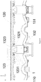
- a surface (that is, a light incidence surface) of the second light guide element 120 facing the first light guide elements 110 is formed with a plurality of corrugated structures 123, such as sawtooth-shaped structures, which are configured to guide light from the first light guide elements 110 to enter the second light guide element and then travel in the first direction, as shown in Figures 4 and 5 .
- the corrugated structures 123 of the linear second light guide element 120 may extend within the range of the width W2 in the third direction Z.
- the corrugated structures 123 each comprise an inclined surface 1231, and respective inclined surfaces are inclined at different angles relative to the first direction X, such that each inclined surface can reflect light entering the corresponding corrugated structure and reaching the inclined surface towards the first direction X.
- Inclined angle and direction of the inclined surface 1231 may be determined according to a position of the inclined surface 1231 relative to the light source, such that most of the light entering the corresponding corrugated structure and reaching the inclined surface are reflected towards the first direction X, and preferably, reflected in a total reflection way towards the first direction X.
- the engagement part 1321 comprises at least one wall face 1323 in contact with air, and the at least one wall face 1323 is configured or arranged to guide, in a reflection way and preferably in a total reflection way, light entering the engagement part and reaching the wall face to be incident into or enter the second light guide element 120 in the first direction X from the portion of the second light guide element 120 overlapping with the engagement part 1321, thus it can be avoided that the light from the first light guide elements 110 is otherwise guided by the engagement part 1321 to other positions of the second light guide element 120 to cause no light exiting from the overlapping portion, and thereby a dark region can be avoided at a light outgoing side of the light guide assembly or of a lighting and/or signaling device equipped with the light guide assembly, improving lighting effect of the lighting and/or signaling device.
- the engagement part 1321 further comprises a hollowed-out structure 1322 penetrating through the engagement part 1321 in the third direction Z, thereby the hollowed-out structure 1322 comprises or defines the wall face 1323.
- the hollowed-out structure 1322 comprises two inner wall faces 1323 inclined in different directions with respect to the first direction X, for example, the wall face 1323 at the left side in the Figures is inclined leftwards relative to the first direction X so as to reflect, in substantially the first direction X, light entering the engagement part 1321 and reaching the wall face from the left light source 1 or the left first light guide element 110, while the wall face 1323 at the right side in the Figures is inclined rightwards relative to the first direction X so as to reflect, in substantially the first direction X, light incident into the engagement part 1321 and reaching the wall face from the right light source 1 or the right first light guide element 110.
- each hollowed-out structure form a substantially inverted-V shape having a vertex directed to the second light guide element 120 or to the first direction X.
- the hollowed-out structure 1322 may have a substantially triangular section shape, but embodiments of the present disclosure are not limited to this, and the hollowed-out structure may also have other section shape, which comprises one or more wall faces configured to guide (for example, reflect) light entering the engagement part towards the first direction X.
- the engagement part may not have the above hollowed-out structure, and instead, the above wall face is defined by an outer surface.
- two or more second connection sections 132' spaced apart from one another may be disposed between the second light guide element 120 and one first connection section 131, and each second connection section 132' may have the above the engagement part 1321, or may have the engagement part 1321' shown in Figure 7 , an outer side surface of the engagement part 1321' defines a wall face 1323, which is inclined relative to the first direction X so as to reflect, in the first direction X, light entering the engagement part 1321' and reaching the wall face from the light source 1 or from the first light guide element 110.
- Two or more second connection sections 132' may be spaced apart from one another in the second direction Y, or may also be spaced apart from one another in the third direction Z. In some examples, the second connection sections 132' are spaced apart from one another in the second direction Y, such that the wall faces 1323 of two adjacent second connection sections 132' may be inclined in different directions with respect to the first direction X so as to form a substantially inverted-V shape, as shown in Figure 7 .
- the wall face 1323 and the inclined surface 1231, which are adjacent to each other in the third direction Z, are aligned or flush with each other, thereby the engagement part 1321 having the wall face 1323 can have the same or similar light guiding function as the second light guide element 120 or other corrugated structures 123, so as to prevent a normal light path from being otherwise adversely affected or interfered by structures for supporting and connecting the light guide elements in the conventional designs, such that light will exit from various positions (including a position where the second light guide element overlaps with the support and connection structure such as the second connection section) on the light outgoing surface of the second light guide element, thereby a dark region can be avoided at the light outgoing side of the light guide assembly or of a lighting and/or signaling device equipped with the light guide assembly, improving lighting effect of the lighting and/or signaling device.
- An embodiment of the present disclosure further provides a lighting or signaling device, comprising a plurality of light sources and the light guide assembly described in any of the above embodiments, each of the first light guide elements of the light guide assembly being configured to receive light from at least one of the light sources.
- the lighting and/or signaling device described in embodiments of the present disclosure may include any kind of lighting lamp and/or signaling lamp for a motor vehicle, for example, a central high mount stop lamp, a direction indicator lamp, a position lamp, a tail stop lamp and the like.
- An embodiment of the present disclosure further provides a motor vehicle comprising the above-described lighting and/or signaling device.
Landscapes
- Engineering & Computer Science (AREA)
- General Engineering & Computer Science (AREA)
- Physics & Mathematics (AREA)
- Microelectronics & Electronic Packaging (AREA)
- Optics & Photonics (AREA)
- Non-Portable Lighting Devices Or Systems Thereof (AREA)
- Planar Illumination Modules (AREA)
Applications Claiming Priority (1)
| Application Number | Priority Date | Filing Date | Title |
|---|---|---|---|
| CN201820290426.9U CN208107969U (zh) | 2018-03-01 | 2018-03-01 | 光导组件、照明或信号指示装置和机动车辆 |
Publications (2)
| Publication Number | Publication Date |
|---|---|
| EP3534063A1 true EP3534063A1 (fr) | 2019-09-04 |
| EP3534063B1 EP3534063B1 (fr) | 2022-08-17 |
Family
ID=64125716
Family Applications (1)
| Application Number | Title | Priority Date | Filing Date |
|---|---|---|---|
| EP19160147.5A Active EP3534063B1 (fr) | 2018-03-01 | 2019-02-28 | Ensemble des réfracteurs de lumière, dispositif d'éclairage ou de signalisation et véhicule à moteur |
Country Status (3)
| Country | Link |
|---|---|
| EP (1) | EP3534063B1 (fr) |
| CN (1) | CN208107969U (fr) |
| ES (1) | ES2929915T3 (fr) |
Cited By (3)
| Publication number | Priority date | Publication date | Assignee | Title |
|---|---|---|---|---|
| DE102019105969B4 (de) | 2018-03-28 | 2021-09-02 | Varroc Lighting Systems, s.r.o. | Verbundlinsenanordnung einer Lichtbaugruppe zur Lichtsammlung und Strahlformgebung |
| WO2023030878A1 (fr) * | 2021-08-31 | 2023-03-09 | HELLA GmbH & Co. KGaA | Dispositif d'éclairage pour véhicules |
| FR3141231A1 (fr) * | 2022-10-25 | 2024-04-26 | Valeo Vision | Module optique pour un dispositif lumineux de signalisation |
Families Citing this family (2)
| Publication number | Priority date | Publication date | Assignee | Title |
|---|---|---|---|---|
| FR3099227A1 (fr) * | 2019-07-26 | 2021-01-29 | Psa Automobiles Sa | Dispositif lumineux pour véhicule automobile apte à émettre simultanément un faisceau lumineux de signalisation et un faisceau lumineux d’illumination. |
| CN116293511A (zh) * | 2021-12-21 | 2023-06-23 | 常州星宇车灯股份有限公司 | 光导装置和出光系统 |
Citations (6)
| Publication number | Priority date | Publication date | Assignee | Title |
|---|---|---|---|---|
| EP2012056A1 (fr) * | 2007-07-02 | 2009-01-07 | Valeo Vision | Dispositif lumineux de signalisation pour véhicule automobile |
| EP2317214A1 (fr) * | 2009-11-02 | 2011-05-04 | Valeo Vision | Dispositif d'éclairage ou de signalisation pour véhicule automobile comprenant un guide de lumière |
| US20130021815A1 (en) * | 2011-07-20 | 2013-01-24 | Koito Manufacturing Co., Ltd. | Vehicular Lamp |
| DE202016106198U1 (de) * | 2015-11-13 | 2017-03-08 | Ford Global Technologies, Llc | Signal- und Tagfahrlichtbaugruppen mit gleichförmiger Beleuchtung für ein Fahrzeug |
| WO2017103267A1 (fr) * | 2015-12-18 | 2017-06-22 | Valeo Vision Belgique | Module lumineux, notamment pour feu stop de véhicule |
| JP2017112065A (ja) * | 2015-12-18 | 2017-06-22 | 株式会社小糸製作所 | 車両用灯具 |
-
2018
- 2018-03-01 CN CN201820290426.9U patent/CN208107969U/zh active Active
-
2019
- 2019-02-28 ES ES19160147T patent/ES2929915T3/es active Active
- 2019-02-28 EP EP19160147.5A patent/EP3534063B1/fr active Active
Patent Citations (6)
| Publication number | Priority date | Publication date | Assignee | Title |
|---|---|---|---|---|
| EP2012056A1 (fr) * | 2007-07-02 | 2009-01-07 | Valeo Vision | Dispositif lumineux de signalisation pour véhicule automobile |
| EP2317214A1 (fr) * | 2009-11-02 | 2011-05-04 | Valeo Vision | Dispositif d'éclairage ou de signalisation pour véhicule automobile comprenant un guide de lumière |
| US20130021815A1 (en) * | 2011-07-20 | 2013-01-24 | Koito Manufacturing Co., Ltd. | Vehicular Lamp |
| DE202016106198U1 (de) * | 2015-11-13 | 2017-03-08 | Ford Global Technologies, Llc | Signal- und Tagfahrlichtbaugruppen mit gleichförmiger Beleuchtung für ein Fahrzeug |
| WO2017103267A1 (fr) * | 2015-12-18 | 2017-06-22 | Valeo Vision Belgique | Module lumineux, notamment pour feu stop de véhicule |
| JP2017112065A (ja) * | 2015-12-18 | 2017-06-22 | 株式会社小糸製作所 | 車両用灯具 |
Cited By (4)
| Publication number | Priority date | Publication date | Assignee | Title |
|---|---|---|---|---|
| DE102019105969B4 (de) | 2018-03-28 | 2021-09-02 | Varroc Lighting Systems, s.r.o. | Verbundlinsenanordnung einer Lichtbaugruppe zur Lichtsammlung und Strahlformgebung |
| WO2023030878A1 (fr) * | 2021-08-31 | 2023-03-09 | HELLA GmbH & Co. KGaA | Dispositif d'éclairage pour véhicules |
| FR3141231A1 (fr) * | 2022-10-25 | 2024-04-26 | Valeo Vision | Module optique pour un dispositif lumineux de signalisation |
| WO2024088832A1 (fr) * | 2022-10-25 | 2024-05-02 | Valeo Vision | Module optique pour un dispositif lumineux de signalisation pour vehicules automobiles |
Also Published As
| Publication number | Publication date |
|---|---|
| CN208107969U (zh) | 2018-11-16 |
| ES2929915T3 (es) | 2022-12-02 |
| EP3534063B1 (fr) | 2022-08-17 |
Similar Documents
| Publication | Publication Date | Title |
|---|---|---|
| EP3534063B1 (fr) | Ensemble des réfracteurs de lumière, dispositif d'éclairage ou de signalisation et véhicule à moteur | |
| US10371341B2 (en) | Vehicle lamp | |
| US11879608B2 (en) | Automotive lamp optical element, automotive lamp module, and vehicle | |
| EP3456587B1 (fr) | Dispositif de réglage de faisceau de lumière, phare de véhicule et véhicule à moteur | |
| EP2762770B1 (fr) | Unité d'éclairage de véhicule | |
| EP3647653A1 (fr) | Phare de véhicule | |
| US20160195230A1 (en) | Lighting system, in particular for a motor vehicle lighting member, comprising a printed circuit board in the plane of the lighting direction | |
| CN108131595B (zh) | 灯具 | |
| CN110220156A (zh) | 光导组件、照明或信号指示装置和机动车辆 | |
| US11047542B2 (en) | Light distribution member, lighting or signaling device and motor vehicle | |
| JP7100530B2 (ja) | 車輌用灯具 | |
| US6796694B2 (en) | Vehicular signal lamp | |
| JP6003178B2 (ja) | 車両用灯具 | |
| US11293615B2 (en) | Vehicle headlamp | |
| JP6943099B2 (ja) | インナーレンズ及び車両用灯具 | |
| US20210404622A1 (en) | Vehicle lamp iii-zone illumination structure, vehicle lamp condenser, automobile illumination module and automobile | |
| CN213542362U (zh) | 车灯光学组件、车灯模组和车辆 | |
| CN220355221U (zh) | 光导构件、照明或信号指示装置和机动车辆 | |
| CN220551817U (zh) | 车辆用灯具 | |
| EP3587909B1 (fr) | Part de lampe de véhicule | |
| US10823364B2 (en) | Vehicular lamp | |
| CN211694710U (zh) | 导光结构、照明装置以及平衡车 | |
| WO2023171479A1 (fr) | Phare de véhicule | |
| JP7084588B2 (ja) | 発光装置及びこれを備えた警光灯 | |
| EP3792548B1 (fr) | Phare de projection |
Legal Events
| Date | Code | Title | Description |
|---|---|---|---|
| PUAI | Public reference made under article 153(3) epc to a published international application that has entered the european phase |
Free format text: ORIGINAL CODE: 0009012 |
|
| STAA | Information on the status of an ep patent application or granted ep patent |
Free format text: STATUS: THE APPLICATION HAS BEEN PUBLISHED |
|
| AK | Designated contracting states |
Kind code of ref document: A1 Designated state(s): AL AT BE BG CH CY CZ DE DK EE ES FI FR GB GR HR HU IE IS IT LI LT LU LV MC MK MT NL NO PL PT RO RS SE SI SK SM TR |
|
| AX | Request for extension of the european patent |
Extension state: BA ME |
|
| STAA | Information on the status of an ep patent application or granted ep patent |
Free format text: STATUS: REQUEST FOR EXAMINATION WAS MADE |
|
| 17P | Request for examination filed |
Effective date: 20200225 |
|
| RBV | Designated contracting states (corrected) |
Designated state(s): AL AT BE BG CH CY CZ DE DK EE ES FI FR GB GR HR HU IE IS IT LI LT LU LV MC MK MT NL NO PL PT RO RS SE SI SK SM TR |
|
| GRAP | Despatch of communication of intention to grant a patent |
Free format text: ORIGINAL CODE: EPIDOSNIGR1 |
|
| STAA | Information on the status of an ep patent application or granted ep patent |
Free format text: STATUS: GRANT OF PATENT IS INTENDED |
|
| INTG | Intention to grant announced |
Effective date: 20220310 |
|
| GRAS | Grant fee paid |
Free format text: ORIGINAL CODE: EPIDOSNIGR3 |
|
| GRAA | (expected) grant |
Free format text: ORIGINAL CODE: 0009210 |
|
| STAA | Information on the status of an ep patent application or granted ep patent |
Free format text: STATUS: THE PATENT HAS BEEN GRANTED |
|
| AK | Designated contracting states |
Kind code of ref document: B1 Designated state(s): AL AT BE BG CH CY CZ DE DK EE ES FI FR GB GR HR HU IE IS IT LI LT LU LV MC MK MT NL NO PL PT RO RS SE SI SK SM TR |
|
| REG | Reference to a national code |
Ref country code: CH Ref legal event code: EP |
|
| REG | Reference to a national code |
Ref country code: DE Ref legal event code: R096 Ref document number: 602019018267 Country of ref document: DE |
|
| REG | Reference to a national code |
Ref country code: IE Ref legal event code: FG4D |
|
| REG | Reference to a national code |
Ref country code: AT Ref legal event code: REF Ref document number: 1512406 Country of ref document: AT Kind code of ref document: T Effective date: 20220915 |
|
| REG | Reference to a national code |
Ref country code: ES Ref legal event code: FG2A Ref document number: 2929915 Country of ref document: ES Kind code of ref document: T3 Effective date: 20221202 |
|
| REG | Reference to a national code |
Ref country code: NL Ref legal event code: MP Effective date: 20220817 |
|
| REG | Reference to a national code |
Ref country code: LT Ref legal event code: MG9D |
|
| PG25 | Lapsed in a contracting state [announced via postgrant information from national office to epo] |
Ref country code: SE Free format text: LAPSE BECAUSE OF FAILURE TO SUBMIT A TRANSLATION OF THE DESCRIPTION OR TO PAY THE FEE WITHIN THE PRESCRIBED TIME-LIMIT Effective date: 20220817 Ref country code: RS Free format text: LAPSE BECAUSE OF FAILURE TO SUBMIT A TRANSLATION OF THE DESCRIPTION OR TO PAY THE FEE WITHIN THE PRESCRIBED TIME-LIMIT Effective date: 20220817 Ref country code: PT Free format text: LAPSE BECAUSE OF FAILURE TO SUBMIT A TRANSLATION OF THE DESCRIPTION OR TO PAY THE FEE WITHIN THE PRESCRIBED TIME-LIMIT Effective date: 20221219 Ref country code: NO Free format text: LAPSE BECAUSE OF FAILURE TO SUBMIT A TRANSLATION OF THE DESCRIPTION OR TO PAY THE FEE WITHIN THE PRESCRIBED TIME-LIMIT Effective date: 20221117 Ref country code: NL Free format text: LAPSE BECAUSE OF FAILURE TO SUBMIT A TRANSLATION OF THE DESCRIPTION OR TO PAY THE FEE WITHIN THE PRESCRIBED TIME-LIMIT Effective date: 20220817 Ref country code: LV Free format text: LAPSE BECAUSE OF FAILURE TO SUBMIT A TRANSLATION OF THE DESCRIPTION OR TO PAY THE FEE WITHIN THE PRESCRIBED TIME-LIMIT Effective date: 20220817 Ref country code: LT Free format text: LAPSE BECAUSE OF FAILURE TO SUBMIT A TRANSLATION OF THE DESCRIPTION OR TO PAY THE FEE WITHIN THE PRESCRIBED TIME-LIMIT Effective date: 20220817 Ref country code: FI Free format text: LAPSE BECAUSE OF FAILURE TO SUBMIT A TRANSLATION OF THE DESCRIPTION OR TO PAY THE FEE WITHIN THE PRESCRIBED TIME-LIMIT Effective date: 20220817 |
|
| REG | Reference to a national code |
Ref country code: AT Ref legal event code: MK05 Ref document number: 1512406 Country of ref document: AT Kind code of ref document: T Effective date: 20220817 |
|
| PG25 | Lapsed in a contracting state [announced via postgrant information from national office to epo] |
Ref country code: PL Free format text: LAPSE BECAUSE OF FAILURE TO SUBMIT A TRANSLATION OF THE DESCRIPTION OR TO PAY THE FEE WITHIN THE PRESCRIBED TIME-LIMIT Effective date: 20220817 Ref country code: IS Free format text: LAPSE BECAUSE OF FAILURE TO SUBMIT A TRANSLATION OF THE DESCRIPTION OR TO PAY THE FEE WITHIN THE PRESCRIBED TIME-LIMIT Effective date: 20221217 Ref country code: HR Free format text: LAPSE BECAUSE OF FAILURE TO SUBMIT A TRANSLATION OF THE DESCRIPTION OR TO PAY THE FEE WITHIN THE PRESCRIBED TIME-LIMIT Effective date: 20220817 |
|
| PG25 | Lapsed in a contracting state [announced via postgrant information from national office to epo] |
Ref country code: SM Free format text: LAPSE BECAUSE OF FAILURE TO SUBMIT A TRANSLATION OF THE DESCRIPTION OR TO PAY THE FEE WITHIN THE PRESCRIBED TIME-LIMIT Effective date: 20220817 Ref country code: RO Free format text: LAPSE BECAUSE OF FAILURE TO SUBMIT A TRANSLATION OF THE DESCRIPTION OR TO PAY THE FEE WITHIN THE PRESCRIBED TIME-LIMIT Effective date: 20220817 Ref country code: DK Free format text: LAPSE BECAUSE OF FAILURE TO SUBMIT A TRANSLATION OF THE DESCRIPTION OR TO PAY THE FEE WITHIN THE PRESCRIBED TIME-LIMIT Effective date: 20220817 Ref country code: AT Free format text: LAPSE BECAUSE OF FAILURE TO SUBMIT A TRANSLATION OF THE DESCRIPTION OR TO PAY THE FEE WITHIN THE PRESCRIBED TIME-LIMIT Effective date: 20220817 |
|
| PGFP | Annual fee paid to national office [announced via postgrant information from national office to epo] |
Ref country code: FR Payment date: 20230227 Year of fee payment: 5 |
|
| REG | Reference to a national code |
Ref country code: DE Ref legal event code: R097 Ref document number: 602019018267 Country of ref document: DE |
|
| PG25 | Lapsed in a contracting state [announced via postgrant information from national office to epo] |
Ref country code: SK Free format text: LAPSE BECAUSE OF FAILURE TO SUBMIT A TRANSLATION OF THE DESCRIPTION OR TO PAY THE FEE WITHIN THE PRESCRIBED TIME-LIMIT Effective date: 20220817 Ref country code: EE Free format text: LAPSE BECAUSE OF FAILURE TO SUBMIT A TRANSLATION OF THE DESCRIPTION OR TO PAY THE FEE WITHIN THE PRESCRIBED TIME-LIMIT Effective date: 20220817 |
|
| PGFP | Annual fee paid to national office [announced via postgrant information from national office to epo] |
Ref country code: TR Payment date: 20230221 Year of fee payment: 5 |
|
| PLBE | No opposition filed within time limit |
Free format text: ORIGINAL CODE: 0009261 |
|
| STAA | Information on the status of an ep patent application or granted ep patent |
Free format text: STATUS: NO OPPOSITION FILED WITHIN TIME LIMIT |
|
| PG25 | Lapsed in a contracting state [announced via postgrant information from national office to epo] |
Ref country code: AL Free format text: LAPSE BECAUSE OF FAILURE TO SUBMIT A TRANSLATION OF THE DESCRIPTION OR TO PAY THE FEE WITHIN THE PRESCRIBED TIME-LIMIT Effective date: 20220817 |
|
| P01 | Opt-out of the competence of the unified patent court (upc) registered |
Effective date: 20230602 |
|
| 26N | No opposition filed |
Effective date: 20230519 |
|
| PG25 | Lapsed in a contracting state [announced via postgrant information from national office to epo] |
Ref country code: SI Free format text: LAPSE BECAUSE OF FAILURE TO SUBMIT A TRANSLATION OF THE DESCRIPTION OR TO PAY THE FEE WITHIN THE PRESCRIBED TIME-LIMIT Effective date: 20220817 |
|
| PG25 | Lapsed in a contracting state [announced via postgrant information from national office to epo] |
Ref country code: MC Free format text: LAPSE BECAUSE OF FAILURE TO SUBMIT A TRANSLATION OF THE DESCRIPTION OR TO PAY THE FEE WITHIN THE PRESCRIBED TIME-LIMIT Effective date: 20220817 |
|
| REG | Reference to a national code |
Ref country code: CH Ref legal event code: PL |
|
| REG | Reference to a national code |
Ref country code: BE Ref legal event code: MM Effective date: 20230228 |
|
| GBPC | Gb: european patent ceased through non-payment of renewal fee |
Effective date: 20230228 |
|
| PG25 | Lapsed in a contracting state [announced via postgrant information from national office to epo] |
Ref country code: LU Free format text: LAPSE BECAUSE OF NON-PAYMENT OF DUE FEES Effective date: 20230228 Ref country code: LI Free format text: LAPSE BECAUSE OF NON-PAYMENT OF DUE FEES Effective date: 20230228 Ref country code: CH Free format text: LAPSE BECAUSE OF NON-PAYMENT OF DUE FEES Effective date: 20230228 |
|
| REG | Reference to a national code |
Ref country code: IE Ref legal event code: MM4A |
|
| PG25 | Lapsed in a contracting state [announced via postgrant information from national office to epo] |
Ref country code: GB Free format text: LAPSE BECAUSE OF NON-PAYMENT OF DUE FEES Effective date: 20230228 |
|
| PG25 | Lapsed in a contracting state [announced via postgrant information from national office to epo] |
Ref country code: IE Free format text: LAPSE BECAUSE OF NON-PAYMENT OF DUE FEES Effective date: 20230228 Ref country code: GB Free format text: LAPSE BECAUSE OF NON-PAYMENT OF DUE FEES Effective date: 20230228 |
|
| PG25 | Lapsed in a contracting state [announced via postgrant information from national office to epo] |
Ref country code: BE Free format text: LAPSE BECAUSE OF NON-PAYMENT OF DUE FEES Effective date: 20230228 |
|
| PGFP | Annual fee paid to national office [announced via postgrant information from national office to epo] |
Ref country code: ES Payment date: 20240306 Year of fee payment: 6 |
|
| PGFP | Annual fee paid to national office [announced via postgrant information from national office to epo] |
Ref country code: DE Payment date: 20240213 Year of fee payment: 6 Ref country code: CZ Payment date: 20240117 Year of fee payment: 6 |