EP3534059A2 - Luminaire - Google Patents
Luminaire Download PDFInfo
- Publication number
- EP3534059A2 EP3534059A2 EP19160428.9A EP19160428A EP3534059A2 EP 3534059 A2 EP3534059 A2 EP 3534059A2 EP 19160428 A EP19160428 A EP 19160428A EP 3534059 A2 EP3534059 A2 EP 3534059A2
- Authority
- EP
- European Patent Office
- Prior art keywords
- reflector
- heat sink
- relative
- light
- intermediate element
- Prior art date
- Legal status (The legal status is an assumption and is not a legal conclusion. Google has not performed a legal analysis and makes no representation as to the accuracy of the status listed.)
- Granted
Links
- 238000001816 cooling Methods 0.000 claims abstract description 9
- 239000004033 plastic Substances 0.000 claims description 4
- 239000000463 material Substances 0.000 claims description 3
- 239000007769 metal material Substances 0.000 claims description 3
- 238000009434 installation Methods 0.000 description 8
- 238000011161 development Methods 0.000 description 7
- 230000018109 developmental process Effects 0.000 description 7
- 230000002093 peripheral effect Effects 0.000 description 6
- 230000008859 change Effects 0.000 description 3
- 238000006073 displacement reaction Methods 0.000 description 3
- 230000007246 mechanism Effects 0.000 description 3
- 230000009471 action Effects 0.000 description 2
- VYZAMTAEIAYCRO-UHFFFAOYSA-N Chromium Chemical compound [Cr] VYZAMTAEIAYCRO-UHFFFAOYSA-N 0.000 description 1
- RYGMFSIKBFXOCR-UHFFFAOYSA-N Copper Chemical compound [Cu] RYGMFSIKBFXOCR-UHFFFAOYSA-N 0.000 description 1
- 206010038743 Restlessness Diseases 0.000 description 1
- 238000007792 addition Methods 0.000 description 1
- 239000003086 colorant Substances 0.000 description 1
- 230000006835 compression Effects 0.000 description 1
- 238000007906 compression Methods 0.000 description 1
- 229910052802 copper Inorganic materials 0.000 description 1
- 239000010949 copper Substances 0.000 description 1
- 230000006735 deficit Effects 0.000 description 1
- 230000001419 dependent effect Effects 0.000 description 1
- 230000000694 effects Effects 0.000 description 1
- 230000002349 favourable effect Effects 0.000 description 1
- PCHJSUWPFVWCPO-UHFFFAOYSA-N gold Chemical compound [Au] PCHJSUWPFVWCPO-UHFFFAOYSA-N 0.000 description 1
- 239000010931 gold Substances 0.000 description 1
- 229910052737 gold Inorganic materials 0.000 description 1
- 230000017525 heat dissipation Effects 0.000 description 1
- 238000001746 injection moulding Methods 0.000 description 1
- 230000007774 longterm Effects 0.000 description 1
- 230000013011 mating Effects 0.000 description 1
- 238000000034 method Methods 0.000 description 1
- 238000012986 modification Methods 0.000 description 1
- 230000004048 modification Effects 0.000 description 1
- 230000036651 mood Effects 0.000 description 1
- 239000004417 polycarbonate Substances 0.000 description 1
- 229920000515 polycarbonate Polymers 0.000 description 1
- 230000008569 process Effects 0.000 description 1
- 230000002035 prolonged effect Effects 0.000 description 1
- 230000005855 radiation Effects 0.000 description 1
- 238000009423 ventilation Methods 0.000 description 1
Images


Classifications
-
- F—MECHANICAL ENGINEERING; LIGHTING; HEATING; WEAPONS; BLASTING
- F21—LIGHTING
- F21V—FUNCTIONAL FEATURES OR DETAILS OF LIGHTING DEVICES OR SYSTEMS THEREOF; STRUCTURAL COMBINATIONS OF LIGHTING DEVICES WITH OTHER ARTICLES, NOT OTHERWISE PROVIDED FOR
- F21V21/00—Supporting, suspending, or attaching arrangements for lighting devices; Hand grips
- F21V21/02—Wall, ceiling, or floor bases; Fixing pendants or arms to the bases
- F21V21/03—Ceiling bases, e.g. ceiling roses
-
- F—MECHANICAL ENGINEERING; LIGHTING; HEATING; WEAPONS; BLASTING
- F21—LIGHTING
- F21V—FUNCTIONAL FEATURES OR DETAILS OF LIGHTING DEVICES OR SYSTEMS THEREOF; STRUCTURAL COMBINATIONS OF LIGHTING DEVICES WITH OTHER ARTICLES, NOT OTHERWISE PROVIDED FOR
- F21V21/00—Supporting, suspending, or attaching arrangements for lighting devices; Hand grips
- F21V21/14—Adjustable mountings
- F21V21/30—Pivoted housings or frames
-
- F—MECHANICAL ENGINEERING; LIGHTING; HEATING; WEAPONS; BLASTING
- F21—LIGHTING
- F21S—NON-PORTABLE LIGHTING DEVICES; SYSTEMS THEREOF; VEHICLE LIGHTING DEVICES SPECIALLY ADAPTED FOR VEHICLE EXTERIORS
- F21S8/00—Lighting devices intended for fixed installation
- F21S8/02—Lighting devices intended for fixed installation of recess-mounted type, e.g. downlighters
- F21S8/026—Lighting devices intended for fixed installation of recess-mounted type, e.g. downlighters intended to be recessed in a ceiling or like overhead structure, e.g. suspended ceiling
-
- F—MECHANICAL ENGINEERING; LIGHTING; HEATING; WEAPONS; BLASTING
- F21—LIGHTING
- F21V—FUNCTIONAL FEATURES OR DETAILS OF LIGHTING DEVICES OR SYSTEMS THEREOF; STRUCTURAL COMBINATIONS OF LIGHTING DEVICES WITH OTHER ARTICLES, NOT OTHERWISE PROVIDED FOR
- F21V14/00—Controlling the distribution of the light emitted by adjustment of elements
- F21V14/02—Controlling the distribution of the light emitted by adjustment of elements by movement of light sources
-
- F—MECHANICAL ENGINEERING; LIGHTING; HEATING; WEAPONS; BLASTING
- F21—LIGHTING
- F21V—FUNCTIONAL FEATURES OR DETAILS OF LIGHTING DEVICES OR SYSTEMS THEREOF; STRUCTURAL COMBINATIONS OF LIGHTING DEVICES WITH OTHER ARTICLES, NOT OTHERWISE PROVIDED FOR
- F21V17/00—Fastening of component parts of lighting devices, e.g. shades, globes, refractors, reflectors, filters, screens, grids or protective cages
- F21V17/02—Fastening of component parts of lighting devices, e.g. shades, globes, refractors, reflectors, filters, screens, grids or protective cages with provision for adjustment
-
- F—MECHANICAL ENGINEERING; LIGHTING; HEATING; WEAPONS; BLASTING
- F21—LIGHTING
- F21V—FUNCTIONAL FEATURES OR DETAILS OF LIGHTING DEVICES OR SYSTEMS THEREOF; STRUCTURAL COMBINATIONS OF LIGHTING DEVICES WITH OTHER ARTICLES, NOT OTHERWISE PROVIDED FOR
- F21V21/00—Supporting, suspending, or attaching arrangements for lighting devices; Hand grips
- F21V21/14—Adjustable mountings
-
- F—MECHANICAL ENGINEERING; LIGHTING; HEATING; WEAPONS; BLASTING
- F21—LIGHTING
- F21V—FUNCTIONAL FEATURES OR DETAILS OF LIGHTING DEVICES OR SYSTEMS THEREOF; STRUCTURAL COMBINATIONS OF LIGHTING DEVICES WITH OTHER ARTICLES, NOT OTHERWISE PROVIDED FOR
- F21V29/00—Protecting lighting devices from thermal damage; Cooling or heating arrangements specially adapted for lighting devices or systems
- F21V29/50—Cooling arrangements
- F21V29/70—Cooling arrangements characterised by passive heat-dissipating elements, e.g. heat-sinks
-
- F—MECHANICAL ENGINEERING; LIGHTING; HEATING; WEAPONS; BLASTING
- F21—LIGHTING
- F21V—FUNCTIONAL FEATURES OR DETAILS OF LIGHTING DEVICES OR SYSTEMS THEREOF; STRUCTURAL COMBINATIONS OF LIGHTING DEVICES WITH OTHER ARTICLES, NOT OTHERWISE PROVIDED FOR
- F21V7/00—Reflectors for light sources
- F21V7/04—Optical design
-
- F—MECHANICAL ENGINEERING; LIGHTING; HEATING; WEAPONS; BLASTING
- F21—LIGHTING
- F21Y—INDEXING SCHEME ASSOCIATED WITH SUBCLASSES F21K, F21L, F21S and F21V, RELATING TO THE FORM OR THE KIND OF THE LIGHT SOURCES OR OF THE COLOUR OF THE LIGHT EMITTED
- F21Y2115/00—Light-generating elements of semiconductor light sources
- F21Y2115/10—Light-emitting diodes [LED]
Definitions
- the present invention relates to a luminaire.
- Luminaires such as recessed luminaires are well known as such. In many cases, in addition to the creation of a pleasant lighting and the ability to align the beam of light to illuminate specific areas or objects targeted, also put emphasis on an aesthetic ceiling image.
- the applicant is known recessed lights, which can be mounted, for example in the manner of a downlight in a suspended ceiling. Furthermore, the Applicant conventional recessed lights are known which are pivotally adapted to align the light cone emitted by the light fitting. While in a kind of conventional lamp by pivoting the light cone out of the vertical out swiveling parts of the lamp out of the ceiling plane and thereby become visible, such protruding pivotal parts of the lamp is avoided in oblique position of the emission direction in another known to the applicant type.
- conventional adjustable lights are often less compact and space-saving constructed as desirable.
- a reduced height may be desirable.
- the invention has for its object to provide a luminaire, which is permanently reliable and easy to adjust the direction of light emission adjustable and / or has a reduced height.
- the lamp should also allow the creation of a discreet and aesthetic ceiling image.
- a luminaire with a light generating device, a heat sink, a reflector and an intermediate element is proposed.
- the cooling body is pivotably coupled to the reflector about a pivot axis relative to the reflector.
- the light generating device is arranged on the heat sink such that light can be emitted by the light generating device into an interior space of the reflector.
- the intermediate element is displaceably mounted on the heat sink relative to the heat sink. It is further provided that the intermediate element has at least one first section provided with a toothing and the reflector has at least one second section provided with a toothing.
- An engagement of the serrations of the first and second sections into one another here counteracts a pivoting of the heat sink relative to the reflector about the pivot axis. For a pivoting of the heat sink relative to the reflector about the pivot axis of the toothings of the first and second portions are disengageable.
- a luminaire with a light-generating device, an at least partially dome-like reflector, and a helmet-shaped heat sink is proposed.
- the cooling body is pivotably coupled to the reflector about a pivot axis relative to the reflector.
- the light generating device is arranged on the heat sink such that light can be emitted by the light generating device into an interior space of the reflector. It is further provided that the heat sink the Reflector overlaps and thereby the reflector is partially received in an inner region of the heat sink.
- One of the findings underlying the present invention is that reliable and accurate adjustment of a luminaire can be achieved by utilizing serrated sections that intermesh.
- a once selected light adjustment can be reliably maintained by positive engagement of the toothings. It is thus possible by means of the teeth a kind of "snapping" in a selected position. An insufficient function of the adjustment mechanism by loosening rivets, screws or the like is avoided by means of the toothings.
- the use of the toothings also allows a fine adjustment of the lamp.
- the lamp is also easy to use to adjust this. In particular, the lamp may further avoid, for example, the need for disassembly of the lamp for the adjustment.
- a reliable adjustability in a simple manner with only a few components, using the heat sink, the intermediate element and the reflector can be realized.
- the adjustment mechanism formed with the toothings is durable and stable.
- Another idea underlying the invention is that with the help of a helmet-like heat sink, which engages over the reflector, a small size and especially low overall height can be made possible at the same time good heat dissipation.
- a pivoting of the heat sink relative to the reflector can be made possible in a simple manner with the helmet-like design of the reflector cross-body heat sink.
- the intermediate element in a direction along which the intermediate element is displaceable relative to the heat sink, acted upon with respect to the heat sink with a spring force.
- the intermediate member can be reliably held in position.
- the engagement of the teeth can be reliably ensured.
- the luminaire has at least one spring device which acts on the intermediate element in relation to the heat sink in such a manner with a spring force that the toothing of the first section is pressed against the toothing of the second section.
- the toothed geometries of the first and second sections can thus be kept in engagement under the bias provided by the spring means.
- the intermediate element is guided rectilinearly displaceable on the heat sink in a development relative to the heat sink.
- the intermediate element and the heat sink can be equipped with guide means designed to correspond to one another.
- Such a guide can be implemented in a relatively simple manner.
- At least the toothing of the second section is arranged along an arc, in particular along a circular arc. In this way, a reliable engagement of the toothings can be made possible for different layers of the intermediate element relative to the reflector.
- the second section provided with a toothing is arranged on an outer side of the reflector. In this way, the second portion for the above-described engagement of the toothings is easily accessible.
- the intermediate element has two first sections each provided with a toothing and the reflector has two second sections each provided with a toothing.
- the intermediate element is formed as an at least partially cap or shell-like component with a recess.
- the intermediate element can take over in this way around the recess around in a space-saving manner a covering function.
- the heat sink is coupled relative to the reflector within a predefined pivoting range pivotally connected to the reflector.
- the reflector has in this case at the rear a passage which allows the emission of light by the light generating device in the interior of the reflector for positions of the heat sink relative to the reflector within the pivoting range.
- the intermediate element is formed according to this embodiment as a cover, which in the positions of the heat sink relative to the reflector within the pivoting range, the passage of the reflector outside of a region of the passage, in the position of the heat sink in the operation of the light generating device for the delivery of light the interior of the reflector is used, each substantially covers.
- the intermediate element can largely cover the passage outside the area used for the light emission into the interior of the reflector, such that in all intended pivot positions of the heat sink, an undesired rear light exit from the interior of the reflector, for example into the space behind a suspended ceiling, is avoided.
- pivot position is intended to include all positions of the heat sink in the pivoting range, in particular the possible end positions, and in particular including a position in which the light output, for example, is vertical to an installation level, if such a position is provided.
- a light exit from the reflector on a rear side of the same, such as through a gap between the heat sink and the reflector can be avoided.
- An intermediate element provided according to this embodiment is advantageous in connection with the toothings provided in a luminaire according to the invention, but may also be useful as a cover element if such serrations are not necessarily provided.
- the swivel range here is in particular an angular range about the pivot axis.
- a size of the angular range is for example about 30 degrees.
- the pivoting range may include an end position in which a main emission direction thereof is oriented substantially normal to an installation plane of the luminaire.
- a "downlight" function with radiation of the light cone can be realized substantially vertically downwards.
- the reflector can be formed at least partially dome-like.
- the rear passage of the reflector may be formed as a through hole in a domed shell-like portion of the reflector.
- the heat sink is designed like a helmet and engages over the reflector and the intermediate element in each case.
- the reflector and the intermediate element are each partially accommodated in an inner region of the heat sink.
- a low overall height of the luminaire can advantageously be achieved, which may be useful in particular with a recessed luminaire.
- the heat sink may be formed in such a way that the heat sink overlaps in one of its end positions relative to the reflector on one side of the pivot axis with the reflector more, and thus receives it in the inner area far more than on the other. In this way, the pivoting is enabled at the same time effective cooling and yet small footprint.
- the reflector has pivot pins which define the pivot axis.
- the heat sink has the pivot pin associated with each recesses.
- the heat sink is in this case latched onto the reflector such that the pivot pins are each pivotably received in one of the recesses.
- the pivot pins of the reflector can engage in the recesses of the heat sink. In this way, the reflector and the heat sink can be coupled by latching mating in a simple manner.
- the luminaire further comprises a lens, which is arranged and arranged for directing and / or bundling the light provided by the light-generating device.
- the intermediate element has a receiving area which is adapted to a size and shape of the lens, preferably a circular area, in which the lens is accommodated at least in sections.
- the receiving region of the intermediate element for the lens is formed, in particular, by a recess of the intermediate element, for example the recess of the intermediate element mentioned above in the case of its at least partially cap-shaped or shell-like design.
- the lens is coupled to the intermediate element in such a way that the teeth of the first and second sections for pivoting the heat sink relative to the reflector can be disengaged by an operator by pressing on the lens from a visible side of the light.
- the pressing by the operator can in particular take place against the spring force provided by the spring device.
- the lamp is designed as a recessed ceiling spotlights. The subtle adjustment of the lamp can often be useful in such a situation installation.
- a frame is further provided, in which the reflector can be latched such that the latched reflector is rotatable about a central axis of the reflector relative to the frame.
- the lamp can be locked in the frame.
- the frame can form a lighting arrangement together with the lamp. In this way, a diverse alignment and adjustment for the light emitted by the light is possible.
- a rotation about the central axis of the reflector can also provide an additional adjustment without this unrest in the appearance of the installation level, for example, the ceiling, get inside.
- a snap makes the light also easy to assemble and disassemble.
- the reflector can be equipped in a development with locking devices, such as spring-loaded balls that allow the engagement of the reflector in the frame and the rotation of the reflector about the central axis.
- locking devices such as spring-loaded balls that allow the engagement of the reflector in the frame and the rotation of the reflector about the central axis.
- the pivot axis about which the heat sink is pivotally coupled to the reflector relative to the reflector is arranged substantially normal to the central axis about which the reflector is rotatable in the frame. This contributes to a versatile and flexible adjustability.
- the frame of the lamp may be formed as a mounting frame, which is for example so installed in a ceiling, that the central axis of the reflector is substantially perpendicular to an installation plane, such as a ceiling plane, aligned.
- the light-generating device can radiate into the interior of the reflector substantially parallel to the central axis.
- the heat sink is formed with a metal material, and the reflector and the intermediate element are each formed with a plastic material.
- a heat sink according to this embodiment is robust and has favorable heat conduction properties, while the reflector and the intermediate element can be made relatively inexpensive and weight saving.
- the heat sink can be die cast, for example.
- the reflector and the intermediate element can be manufactured for example by means of plastic injection molding.
- the light generating device is formed with an LED device, which is arranged on the heat sink.
- the LED device may have one or more LEDs as light sources.
- Such a light generating device can manage with comparatively small space and also contribute to energy savings.
- the light generating device is preferably fixed to the heat sink.
- the heat sink may have a mounting surface for the LED device.
- the LED device can, for example, have an LED circuit board which is mounted directly on the heat sink. Heat generated by the LED device during operation can be effectively dissipated into the heat sink.
- a lamp 1 according to a first embodiment, and components of the lamp 1, are in the FIGS. 1 to 25 shown.
- the lamp 1 is designed as a recessed ceiling spotlight or adjustable "downlight” and creates a discreet ceiling and a pleasant lighting mood in a compact design and with a relatively small diameter.
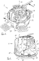
- FIG. 1 shows the lamp 1, which forms a lighting arrangement together with a substantially annular mounting frame 21.
- the frame 21 may, for example, in a round opening in a in FIG. 1 not shown, suspended false ceiling to be installed.
- the mounting frame 21 by means of tab-like fastening means 27 which are coupled, for example, in different heights and positions on an outer side of the frame 21 with the frame 21, be secured in the ceiling area.
- the lamp 1 is releasably engaged in the frame 21 and can relative to the frame 21 about a central axis 22 of a reflector 4 relative to the frame 21st to be twisted.
- the lamp 1 may be rotatable about the central axis 22 with respect to the frame 21 by an angle of 360 degrees or more, or by an angle of slightly less than 360 degrees, for example by about 355 degrees.
- the luminaire 1 has a light generating device 2, a helmet-like heat sink 3, an at least partially dome-shaped reflector 4 and an intermediate element 5.
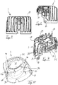
- the heat sink 3 engages in each case the reflector 4 and the intermediate element 5, whereby the reflector 4 and the intermediate element 5 are each received with a portion in an inner region 24 of the heat sink 3, see Fig. 2 and 10 ,
- the light generating device 2 comprises an LED device 23 with one or more LEDs which provide the light to be radiated by the luminaire 1.
- FIG. 10 shows in the inner region 24 of the heat sink 3 a mounting surface 32 thereof, which is formed as a flat inner surface of the heat sink 3.
- the LED device 23 has an LED circuit board, which is mounted directly on the heat sink 3 by means of the mounting surface 32.
- the light generating device 2 is fixed to the heat sink 3 in this way.
- the light generating device 2 is arranged such that it can emit light in an interior 7 of the reflector 4 during operation. This will be explained below.
- the lamp 1 has a lens 19 which is arranged and arranged for directing and / or focusing the light provided by the light-generating device 2.
- the lens 19 is for this, see FIGS. 5 and 6 , disposed in front of the light generating device 19 and has a substantially circular cylindrical outer shape.
- the intermediate element 5 which will be described in more detail below, has a substantially circular recess 14 in the form of a passage opening whose shape and diameter are adapted to the shape and the diameter of the lens 19. A portion of the lens 19 is received in the recess 14. Thus, the recess 14 forms a receiving area 20 for the lens 19.
- FIG. 4 shows that the intermediate element 5 is arranged on a rear and outer side 41 of the reflector 4.
- the reflector 4 is provided on its rear side with a passage 16, see in particular FIGS. 4 and 11-13 ,
- the passage 16 is introduced as a passage opening in a curved, shell-like portion 33 of the reflector 4.
- the passage is slightly elongated and also rounded.
- the passage 16 is larger in area than the recess 14 of the intermediate element 5.
- FIG. 4 lie the recess 14 and the passage 16 one above the other, such that the recess 14 is not covered by parts of the reflector 4.
- the lens 19 protrudes through the recess 14 into the passage 16, see Fig. 6 , In this way, light bundled and / or guided by the light generating device 2 through the lens 19 can be emitted into the interior 7 of the reflector 4.
- the heat sink 3 is pivotally coupled relative to the reflector 4 about a pivot axis 6, which is defined by two pivot pins 17 of the reflector 4 projecting radially outwards. In this way, a pivoting of the heat sink 3 relative to the reflector 4 is made possible within a predefined pivoting range 15, wherein in the first embodiment shown the pivoting area 15 about the pivot axis 6 as an angular range of about 30 degrees relative to the central axis 22, see Fig. 23 , is defined.
- the helmet-like heat sink 3, which is externally provided with a plurality of ribs 28 for improving the cooling effect, see Fig. 1, 2 and 7-10 , Has an inner region 24, which is bounded by an end wall 29 and a peripheral wall 30 of the heat sink 3.
- the peripheral wall 30 has a cutout 31 in a region which extends approximately over half the circumference of the heat sink.
- a cutout 31 is, for pivoted positions of the heat sink 3 relative to its vertical position in Fig. 2 , Made space for the reflector 4 and allows the pivoting of the heat sink 3 about the axis 6.
- Fig. 2 shows how the heat sink 3 in the illustrated in this figure, vertical orientation of the heat sink 3 in one half of the circumference of the reflector 4 between the two pivot pins 17, in Fig. 2 on the left side, the shell-like portion 33 of the reflector 4 largely receives in itself, while in the other half of the circumference of the reflector 4 in this position of the heat sink 3, a part of the shell-like portion 33 protrudes.
- the heat sink 3 and the reflector 4 thus overlap Fig. 2 on one side of the pivot axis 6 more than on the other.
- a targeted alignment of a light cone generated by the light 1 is possible by the adjustment of the heat sink 3 relative to the reflector 4 about the pivot axis 6.
- the heat sink 3 is in this case pivoted together with the intermediate element 5, the lens 19 and the light generating device 2.
- a first end position of the heat sink 3 is in the Figures 2 and 20 to 22 shown, a second end position thereof in the FIGS. 23 to 25 , wherein the end positions exemplified in the sketched embodiment limit the angle range 15.
- the light is emitted into the interior 7 of the reflector 4 along a main direction which is substantially parallel to the center axis 22 of the reflector 4.
- the lamp 1 emits its light cone in this first end position thus substantially parallel to the central axis 22, for example, when installed in a horizontal ceiling vertically downwards.
- Fig. 23-25 For example, it can be seen that components of the luminaire 1 do not protrude from the reflector 4 on the visible side S in any of the pivoting positions.
- the central axis 22 of the reflector 4 can remain unchanged, while the light radiated outwards from the luminaire 1 by the reflector 4 is aligned by means of pivoting of the heat sink 3 together with the light generating device 2 and the lens 19.
- the light 1 thus always gives a discreet, unaltered ceiling image, but still allows an effective alignment of the light cone produced. The viewer thus perceives no change or impairment of the aesthetic appearance of the lamp 1 when adjusting the light cone true.
- the central axis 22 and the pivot axis 6 are in this case substantially perpendicular to each other, wherein in a substantially horizontal installation of the frame 21 in the ceiling, the pivot axis 6 horizontally and the central axis 22 are aligned vertically.
- the central axis 22 is in this case in particular perpendicular to an installation level, not shown, which corresponds for example to the ceiling plane. The rotation of the lamp 1 about the central axis 22 does not disturb the ceiling image.
- the heat sink 3 has, see for example Fig. 2 . 7, 8, 10 , Recesses 18, which are designed as round passage openings and are arranged at a distance of 180 degrees along the circumference of the heat sink 3.
- the recesses 18 are provided adjacent to an outer edge 34 of the peripheral wall 30 and the two end portions of the cutout 31.
- the engagement of the lamp 1 in the frame 21 is made possible by means arranged on the reflector 4 locking devices 35.
- the locking devices 35 are respectively formed as a spring-loaded and radially outwardly facing ball.
- the latching devices 35 can also be referred to as ball catchers.
- the balls are each received in a suitable receptacle 36 on the reflector 4.
- Three receptacles 36 for balls of the locking devices 35 are arranged at a distance corresponding to an angle W of 120 degrees about the central axis 22 on the outer circumference of the reflector 4, see in particular Fig. 12 ,
- the balls can engage in a circumferential groove of the frame 21 and also allow twisting of the latched reflector 4 about the central axis 22.
- the engagement by means of the locking means 35 is such that the latching connection of the lamp 1 and frame 21 can be released, which also a simple disassembly of the lamp 1 is possible.
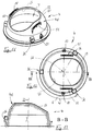
- the formed with a cap or shell-like shape intermediate element 5 is in the Figures 16-19 shown in more detail.
- the intermediate element 5 in each case a first portion 9, wherein each of the two first portions 9 is provided in each case with a toothing 8.
- the intermediate member 5 is provided with three pin-like guide means 38 arranged in parallel with each other and spaced at a distance corresponding to an angle of W 'of about 120 degrees around the recess 14.
- the guide means 38 and the serrations 8 point in the opposite direction.
- Each toothing 8 has in the illustrated embodiment, for example, five teeth.
- the sections 9 are arranged symmetrically to the axis 37.
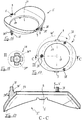
- the reflector 4, in the Figures 11-15 is shown in more detail, has on both sides of a symmetry axis 39 each have a second portion 11 on the outside 41 of the reflector 4.
- Each of the two sections 11 is provided with a toothing 10.
- Each of the serrations 10 is along a circular arc 13, see Fig. 15 arranged, wherein the circle center of the arc 13 is located substantially on the axis 6.
- each of the serrations 10 exemplarily has a number of 16 teeth along the arc 13.
- the sections 11 are arranged symmetrically to the axis 39.
- the heat sink 3 is, see for example Fig. 10 , equipped with three guide means 40 which are formed as open to the inner region 24 recesses in the heat sink 3.
- the guide means 40 correspond in shape and positioning the guide means 38 of the intermediate member 5, such that the intermediate member 5 can be inserted into the inner region 24 and in this case the pin-like Guiding devices 38 are each inserted into the recess-shaped guide means 40.
- the intermediate element 5 along a direction of displacement V parallel to the extension direction of the guide means 38, and thus, for example, in Fig. 6 in the vertical direction, slidably mounted on the heat sink 3.
- the intermediate element 5 can thus be displaced parallel to the direction V relative to the heat sink 3.
- a spring device 12 designed in each case as a compression spring is placed on each of the peg-shaped guide devices 38 between the heat sink 3 and the intermediate element 5. See for example 3 and 4 in which the spring devices 12 are plugged onto pins which serve as the guide means 38.
- the guide means 38 are each formed with a thicker and a thinner portion, which merge into one another in the region of a step 38 '.
- the spring device 12 can each rest on the step 38 ', see 3 and 4 , Lateral guidance may be achieved by an outer surface 38 "of the thicker portions of the guides 38.
- the 3 and 4 show the guide means 38 in a first variant in which the respective thicker and thinner portion are formed with a substantially cylindrical outer surface which is uninterrupted in its circumferential direction.
- the outer surfaces of the guide means 38 in the Figures 16-19 provided in a variant with additional longitudinal grooves 38 '", but in turn the spring device 12 is seated on the step 38'.
- the spring means 12 bias the intermediate member 5 with a spring force F parallel to the direction V, see, for example Fig. 3, 4 which is oriented in the direction away from the heat sink 3 and towards the reflector 4.
- the spring devices 12 are based on the heat sink 3.
- the serrations 8 are pressed against the serrations 10 and engage each other.
- the design of the serrations 8 is made such that the teeth 8 of the shorter executed first portion 9 along the circular arc 13 at different locations in the teeth 10 of the longer formed second portion 11 can engage.
- the toothings 8 and 10 are therefore designed to be coordinated with one another in order to be able to realize such an intervention.
- the lamp 1 makes it possible to change the heat sink 3 and thus the orientation of the emitted light without the lamp 1 has to be removed from the frame 21.
- an operator presses on the visible side S of the luminaire 1, see for example Fig. 5 or 6 , against the spring force F on the lens 19.
- the lens 19 is slidable in relation to the heat sink 3 and coupled to the intermediate element 5 that stand out by pressing on the lens 19, the teeth 8 and 10 against the direction of force F from each other and disengage.
- the displacement by which the intermediate element 5 is displaceable against the spring force F sufficient so that the serrations 8, 10 can be disengaged.
- the lens 19 is thus pressed in the direction of the heat sink 3.
- the heat sink 3 can be pivoted together with the light generating device 2, the intermediate element 5 and the lens 19 about the pivot axis 6.
- the operator takes the pressure away from the lens 19, whereby the engagement of the toothings 8 and 10 is restored and the desired orientation of the heat sink 3 is fixed.
- the heat sink 3 can be kept in any desired positions thereof in the pivoting area 15.
- the lens 19 may for example be secured in the recess 14 on the intermediate element 5.
- An adjustment about the central axis 22 can be done without having to remove the lamp 1 from the frame 21.
- the lamp 1 can be adjusted versatile without the need for disassembly.
- a dimension of the passage 16 in the reflector 4 substantially corresponds to a diameter of the recess 14 in the intermediate element.
- the lens 19 projects, whereby with the aid of the lens 19 guided and / or focused light can be discharged into the interior 7 of the reflector 4.
- the intermediate element 5 moves with the heat sink 3 and moves in the region of the outer side 41 of the reflector 4 in such a way that outside the region of the lens 19, the passage 16 always remains substantially covered. See for example Fig. 5 Do this for a vertical position of the heat sink 3, and for example Fig. 24 which illustrates the covering of the passage for a tilted position of the heat sink 3.
- the intermediate element 5 thus acts as a cover element which can be displaced on the reflector outer side 41 and which moves with the cooling body 3 when pivoting about the axis 6.
- the intermediate element 5 avoids such a gap in the vertical end position of the heat sink 3, this is made Fig. 24 for an oblique position of the heat sink 3 clearly.
- the region 26 is covered by the intermediate element 5, although the heat sink 3 in this figure does not completely cover the region 26.
- the intermediate element 5 covers the region 26 present in the position shown despite simultaneous coverage by the heat sink 3.
- a lamp 1 according to a variant of the first embodiment with a modified heat sink 3 show the Figures 26-30 , wherein the lamp 1 according to Fig. 26-30 only therein of the lamp 1, as described above for the first embodiment, distinguishes that in Fig. 26-30 the heat sink 3 between some of the cooling fins 28 is additionally broken, and thus has 28 openings 42 between some of the ribs. Through the openings 28, a portion of the intermediate element 5 is visible, which in turn advantageously provides, in addition to the function of the toothing 8, a covering function.
- the openings 42 can contribute to weight savings and improve ventilation of the outside of the reflector 41 and the gap between the heat sink 3 and reflector 4.
- a luminaire 101 with a light generating device 2, a heat sink 103, a reflector 104 and an intermediate element 105 according to a second embodiment show the FIGS. 31 and 32 ,
- the second embodiment differs from the first embodiment in terms of the shape of the heat sink 103, which in the second embodiment on the same side thereof, the pivoting of the heat sink 103 away from an opening of the reflector 104 and in Fig. 32 moves upward, extends less far down over the reflector 104 and thus the reflector 104 thus overlaps, but less largely absorbs itself.
- the heat sink 3, 103 is formed of a metal material, for example, die-cast.
- the reflector 4, 104 and the intermediate element 5, 105 are each made of a plastic material, for example injection-molded.
- the reflector 4, 104 and the intermediate element 5, 105 may be made of a polycarbonate.
- the reflector 4, 104, and if desired also the intermediate element 5, 105 can be provided in a number of different colors, for example black, white, copper, chrome or gold.
- the reflector 4, 104, and if desired also the intermediate element 5, 105 may be vacuum-coated.
Landscapes
- Engineering & Computer Science (AREA)
- General Engineering & Computer Science (AREA)
- Arrangement Of Elements, Cooling, Sealing, Or The Like Of Lighting Devices (AREA)
- Non-Portable Lighting Devices Or Systems Thereof (AREA)
Abstract
Die Erfindung betrifft eine erste Leuchte (1, 101) mit einer Lichterzeugungseinrichtung (2), einem Kühlkörper (3, 103), einem Reflektor (4, 104) und einem Zwischenelement (5, 105). Der Kühlkörper ist um eine Schwenkachse (6) relativ zu dem Reflektor schwenkbar mit diesem gekoppelt. Von der Lichterzeugungseinrichtung kann Licht in einen Innenraum des Reflektors abgegeben werden. Das Zwischenelement ist an dem Kühlkörper relativ zu diesem verschiebbar gelagert und weist mindestens einen ersten mit einer Zahnung (8) versehenen Abschnitt (9) auf. Der Reflektor weist mindestens einen zweiten mit einer Zahnung (10) versehenen Abschnitt (11) auf. Ein Eingriff der Zahnungen der ersten und zweiten Abschnitte ineinander wirkt einem Verschwenken des Kühlkörpers relativ zu dem Reflektor um die Schwenkachse entgegen. Für ein Verschwenken des Kühlkörpers relativ zu dem Reflektor um die Schwenkachse sind die Zahnungen der ersten und zweiten Abschnitte außer Eingriff bringbar. Die Erfindung betrifft ferner eine zweite Leuchte, wobei ein helmartig ausgebildeter Kühlkörper um eine Schwenkachse relativ zu einem zumindest abschnittsweise kuppelartigen Reflektor schwenkbar mit diesem gekoppelt ist. Der Kühlkörper übergreift den Reflektor, wodurch der Reflektor abschnittsweise in einem Innenbereich des Kühlkörpers aufgenommen ist.The invention relates to a first luminaire (1, 101) having a light generating device (2), a heat sink (3, 103), a reflector (4, 104) and an intermediate element (5, 105). The heat sink is pivotally coupled to the reflector about a pivot axis (6) relative to the reflector. From the light generating device, light can be emitted into an interior of the reflector. The intermediate element is mounted so as to be displaceable relative to the cooling body and has at least one first section (9) provided with a toothing (8). The reflector has at least one second section (11) provided with a toothing (10). Engagement of the serrations of the first and second sections into one another counteracts pivoting of the heat sink relative to the reflector about the pivot axis. For a pivoting of the heat sink relative to the reflector about the pivot axis of the toothings of the first and second portions are disengageable. The invention further relates to a second lamp, wherein a helmet-like heat sink is pivotally coupled to a reflector about an axis of rotation relative to an at least partially dome-like reflector. The heat sink engages over the reflector, whereby the reflector is partially received in an inner region of the heat sink.
Description
Die vorliegende Erfindung betrifft eine Leuchte.The present invention relates to a luminaire.
Wenngleich die Erfindung im Zusammenhang mit Leuchten vielerlei Art und für verschiedenste Anwendungsbereiche nützlich sein kann, werden die Erfindung und die ihr zu Grunde liegende Problematik nachfolgend am Beispiel einer Einbauleuchte näher erläutert.Although the invention may be useful in connection with lights of many kinds and for a variety of applications, the invention and the underlying problems are explained below using the example of a recessed luminaire.
Leuchten wie beispielsweise Einbauleuchten sind als solche allgemein bekannt. In vielen Fällen wird, neben der Schaffung einer angenehmen Beleuchtung und der Möglichkeit, den Lichtkegel der Leuchte ausrichten zu können, um bestimmte Bereiche oder Gegenstände gezielt zu beleuchten, auch Wert auf ein ästhetisches Deckenbild gelegt.Luminaires such as recessed luminaires are well known as such. In many cases, in addition to the creation of a pleasant lighting and the ability to align the beam of light to illuminate specific areas or objects targeted, also put emphasis on an aesthetic ceiling image.
Der Anmelderin sind Einbauleuchten bekannt, die beispielsweise nach Art eines Downlights in einer abgehängten Decke montiert werden können. Ferner sind der Anmelderin herkömmliche derartige Einbauleuchten bekannt, die schwenkbar ausgebildet sind, um den von der Leuchte abgegebenen Lichtkegel passend ausrichten zu können. Während bei einer Art herkömmlicher Leuchte durch Verschwenken des Lichtkegels aus der Vertikalen heraus verschwenkbare Bestandteile der Leuchte aus der Deckenebene herausschwenken und dadurch sichtbar werden, wird ein derartiges Hervorstehen schwenkbarer Teile der Leuchte bei Schrägstellung der Abstrahlrichtung bei einer anderen der Anmelderin bekannten Bauart vermieden.The applicant is known recessed lights, which can be mounted, for example in the manner of a downlight in a suspended ceiling. Furthermore, the Applicant conventional recessed lights are known which are pivotally adapted to align the light cone emitted by the light fitting. While in a kind of conventional lamp by pivoting the light cone out of the vertical out swiveling parts of the lamp out of the ceiling plane and thereby become visible, such protruding pivotal parts of the lamp is avoided in oblique position of the emission direction in another known to the applicant type.
Bei herkömmlichen verstellbaren Leuchten kann es vorkommen, dass sich einzelne Bauelemente eines Verstellmechanismus, wie beispielsweise Verbindungselemente in Gestalt von Schrauben oder Nieten, auf Dauer und nach längerem Gebrauch, beispielsweise durch Abnutzung nach längerer Einsatzzeit, oder auch aufgrund von Wärmeeinwirkung, lockern. Selbst wenn die Leuchte dennoch nach wie vor sicher gehalten ist, kann dies unerwünscht sein, da in einem solchen Fall der Verstellmechanismus vielfach nicht mehr wie vorgesehen funktioniert und beispielsweise die vom Benutzer gewählte, gewünschte Ausrichtung nicht mehr zuverlässig beibehält.In conventional adjustable lights, it may happen that individual components of an adjustment mechanism, such as fasteners in the form of screws or rivets, in the long term and after prolonged use, for example, by wear after a long time, or due to exposure to heat loosen. Even if the lamp is still kept safe, this may be undesirable because in such a case, the adjustment often no longer works as intended and, for example, no longer reliably maintains the desired orientation selected by the user.
Darüber hinaus sind herkömmliche verstellbare Leuchten vielfach weniger kompakt und platzsparend aufgebaut, als dies wünschenswert erscheint. Insbesondere im Falle von Einbauleuchten kann zum Beispiel eine verringerte Bauhöhe wünschenswert sein.In addition, conventional adjustable lights are often less compact and space-saving constructed as desirable. In particular, in the case of recessed lighting, for example, a reduced height may be desirable.
Dies ist ein Zustand, den es zu verbessern gilt.This is a condition to be improved.
Vor diesem Hintergrund liegt der Erfindung die Aufgabe zugrunde, eine Leuchte anzugeben, die auf Dauer zuverlässig und einfach zur Ausrichtung der Lichtabstrahlrichtung verstellbar ist und/oder eine verringerte Bauhöhe aufweist. Insbesondere soll die Leuchte zudem die Schaffung eines dezenten und ästhetischen Deckenbildes ermöglichen.Against this background, the invention has for its object to provide a luminaire, which is permanently reliable and easy to adjust the direction of light emission adjustable and / or has a reduced height. In particular, the lamp should also allow the creation of a discreet and aesthetic ceiling image.
Erfindungsgemäß wird diese Aufgabe durch eine Leuchte mit den Merkmalen des Patentanspruchs 1 und/oder durch eine Leuchte mit den Merkmalen des Patentanspruchs 15 gelöst.This object is achieved by a lamp with the features of
Demgemäß wird eine Leuchte mit einer Lichterzeugungseinrichtung, einem Kühlkörper, einem Reflektor und einem Zwischenelement vorgeschlagen. Hierbei ist der Kühlkörper um eine Schwenkachse relativ zu dem Reflektor schwenkbar mit dem Reflektor gekoppelt. Die Lichterzeugungseinrichtung ist an dem Kühlkörper derart angeordnet, dass von der Lichterzeugungseinrichtung Licht in einen Innenraum des Reflektors abgegeben werden kann. Das Zwischenelement ist an dem Kühlkörper relativ zu dem Kühlkörper verschiebbar gelagert. Ferner ist vorgesehen, dass das Zwischenelement mindestens einen ersten mit einer Zahnung versehenen Abschnitt aufweist und der Reflektor mindestens einen zweiten mit einer Zahnung versehenen Abschnitt aufweist. Ein Eingriff der Zahnungen der ersten und zweiten Abschnitte ineinander wirkt hierbei einem Verschwenken des Kühlkörpers relativ zu dem Reflektor um die Schwenkachse entgegen. Für ein Verschwenken des Kühlkörpers relativ zu dem Reflektor um die Schwenkachse sind die Zahnungen der ersten und zweiten Abschnitte außer Eingriff bringbar.Accordingly, a luminaire with a light generating device, a heat sink, a reflector and an intermediate element is proposed. In this case, the cooling body is pivotably coupled to the reflector about a pivot axis relative to the reflector. The light generating device is arranged on the heat sink such that light can be emitted by the light generating device into an interior space of the reflector. The intermediate element is displaceably mounted on the heat sink relative to the heat sink. It is further provided that the intermediate element has at least one first section provided with a toothing and the reflector has at least one second section provided with a toothing. An engagement of the serrations of the first and second sections into one another here counteracts a pivoting of the heat sink relative to the reflector about the pivot axis. For a pivoting of the heat sink relative to the reflector about the pivot axis of the toothings of the first and second portions are disengageable.
Ferner wird eine Leuchte mit einer Lichterzeugungseinrichtung, einem zumindest abschnittsweise kuppelartigen Reflektor, und einem helmartig ausgebildeten Kühlkörper vorgeschlagen. Hierbei ist der Kühlkörper um eine Schwenkachse relativ zu dem Reflektor schwenkbar mit dem Reflektor gekoppelt. Die Lichterzeugungseinrichtung ist an dem Kühlkörper derart angeordnet, dass von der Lichterzeugungseinrichtung Licht in einen Innenraum des Reflektors abgegeben werden kann. Ferner ist vorgesehen, dass der Kühlkörper den Reflektor übergreift und hierdurch der Reflektor abschnittsweise in einem Innenbereich des Kühlkörpers aufgenommen ist.Furthermore, a luminaire with a light-generating device, an at least partially dome-like reflector, and a helmet-shaped heat sink is proposed. In this case, the cooling body is pivotably coupled to the reflector about a pivot axis relative to the reflector. The light generating device is arranged on the heat sink such that light can be emitted by the light generating device into an interior space of the reflector. It is further provided that the heat sink the Reflector overlaps and thereby the reflector is partially received in an inner region of the heat sink.
Eine der vorliegenden Erfindung zu Grunde liegende Erkenntnis besteht darin, dass eine verlässliche und genaue Einstellung einer Leuchte durch Nutzung gezahnter Abschnitte, die ineinander eingreifen, erreichbar ist. Ein einmal gewählte Leuchteneinstellung kann durch formschlüssigen Eingriff der Zahnungen ineinander zuverlässig erhalten bleiben. Es wird somit mittels der Zahnungen eine Art "Einrasten" in einer gewählten Stellung möglich. Eine unzureichende Funktion des Verstellmechanismus durch sich lockernde Nieten, Schrauben oder ähnliches wird mit Hilfe der Zahnungen vermieden. Insbesondere ermöglicht die Nutzung der Zahnungen ferner auch eine feine Einstellung der Leuchte. Die Leuchte ist darüber hinaus einfach bedienbar, um diese zu verstellen. Insbesondere kann die Leuchte ferner zum Beispiel die Notwendigkeit einer Demontage der Leuchte für das Verstellen vermeiden. Zudem kann eine zuverlässige Verstellbarkeit in einfacher Weise mit nur wenigen Bauteilen, unter Nutzung des Kühlkörpers, des Zwischenelements und des Reflektors, realisiert werden. Der mit den Zahnungen gebildete Verstellmechanismus ist langlebig und stabil. Eine weitere der Erfindung zu Grunde liegende Idee besteht darin, dass mit Hilfe eines helmartigen Kühlkörpers, der den Reflektor übergreift, eine geringe Baugröße und insbesondere geringe Bauhöhe bei zugleich guter Wärmeabfuhr ermöglicht werden kann. Zudem kann mit der helmartigen Ausbildung des den Reflektor übergreifenden Kühlkörpers ein Verschwenken des Kühlkörpers relativ zu dem Reflektor in einfacher Weise ermöglicht werden.One of the findings underlying the present invention is that reliable and accurate adjustment of a luminaire can be achieved by utilizing serrated sections that intermesh. A once selected light adjustment can be reliably maintained by positive engagement of the toothings. It is thus possible by means of the teeth a kind of "snapping" in a selected position. An insufficient function of the adjustment mechanism by loosening rivets, screws or the like is avoided by means of the toothings. In particular, the use of the toothings also allows a fine adjustment of the lamp. The lamp is also easy to use to adjust this. In particular, the lamp may further avoid, for example, the need for disassembly of the lamp for the adjustment. In addition, a reliable adjustability in a simple manner with only a few components, using the heat sink, the intermediate element and the reflector can be realized. The adjustment mechanism formed with the toothings is durable and stable. Another idea underlying the invention is that with the help of a helmet-like heat sink, which engages over the reflector, a small size and especially low overall height can be made possible at the same time good heat dissipation. In addition, a pivoting of the heat sink relative to the reflector can be made possible in a simple manner with the helmet-like design of the reflector cross-body heat sink.
Indem eine Verstellung der Leuchte bei der Erfindung mit Hilfe eines Verschwenkens des Kühlkörpers zusammen mit der an diesem angeordneten Lichterzeugungseinrichtung erfolgt, kann ein Herausschwenken des Reflektors zum Beispiel aus einer Deckenebene vermieden werden. Ein Betrachter der Leuchte erkennt somit lediglich an dem abgestrahlten Lichtkegel die eingestellte Hauptabstrahlrichtung, also beispielsweise, ob ein Lichtkegel vertikal oder schräg abgestrahlt wird. Eine störende Veränderung des Deckenbildes kann verhindert werden. Ein unruhiges Deckenbild, wie es entstehen kann, wenn nach Einstellvorgängen die Leuchte vom Betrachter anders wahrgenommen wird als vorher, etwa weil durch das Einstellen Leuchtenbestandteile in den Raum ragen, kann vermieden werden.By an adjustment of the lamp in the invention by means of a pivoting of the heat sink takes place together with the light generating means arranged thereon, a pivoting out of the reflector, for example, from a ceiling plane can be avoided. An observer of the luminaire thus only recognizes the set main emission direction on the emitted light cone, that is, for example, whether a cone of light is emitted vertically or obliquely. A disturbing change of the ceiling picture can be prevented. An uneasy ceiling image, as it can occur if the light is perceived differently by the viewer after setting operations than before, for example, because by adjusting luminaire components protrude into the room, can be avoided.
Vorteilhafte Ausgestaltungen und Weiterbildungen der Erfindung ergeben sich aus den Unteransprüchen sowie aus der Beschreibung unter Bezugnahme auf die Figuren der Zeichnung.Advantageous embodiments and modifications of the invention will become apparent from the dependent claims and from the description with reference to the figures of the drawing.
In einer Ausgestaltung ist das Zwischenelement in einer Richtung, längs der das Zwischenelement relativ zu dem Kühlkörper verschiebbar ist, in Bezug auf den Kühlkörper mit einer Federkraft beaufschlagt. Somit kann das Zwischenelement zuverlässig in Position gehalten werden. Insbesondere kann der Eingriff der Zahnungen zuverlässig sichergestellt werden.In one embodiment, the intermediate element in a direction along which the intermediate element is displaceable relative to the heat sink, acted upon with respect to the heat sink with a spring force. Thus, the intermediate member can be reliably held in position. In particular, the engagement of the teeth can be reliably ensured.
In einer Ausgestaltung weist die Leuchte mindestens eine Federeinrichtung auf, welche das Zwischenelement in Bezug auf den Kühlkörper derart mit einer Federkraft beaufschlagt, dass die Zahnung des ersten Abschnitts gegen die Zahnung des zweiten Abschnitts gedrückt wird. Die gezahnten Geometrien der ersten und zweiten Abschnitte können somit unter der mittels der Federeinrichtung bereitgestellten Vorspannung im Eingriff gehalten werden.In one embodiment, the luminaire has at least one spring device which acts on the intermediate element in relation to the heat sink in such a manner with a spring force that the toothing of the first section is pressed against the toothing of the second section. The toothed geometries of the first and second sections can thus be kept in engagement under the bias provided by the spring means.
Das Zwischenelement ist in einer Weiterbildung relativ zu dem Kühlkörper geradlinig verschiebbar an dem Kühlkörper geführt. Hierfür können das Zwischenelement und der Kühlkörper mit zueinander korrespondierend ausgebildeten Führungseinrichtungen ausgestattet sein. Eine derartige Führung kann in vergleichsweise einfacher Weise umgesetzt werden.The intermediate element is guided rectilinearly displaceable on the heat sink in a development relative to the heat sink. For this purpose, the intermediate element and the heat sink can be equipped with guide means designed to correspond to one another. Such a guide can be implemented in a relatively simple manner.
In einer Ausgestaltung ist zumindest die Zahnung des zweiten Abschnitts entlang eines Bogens, insbesondere entlang eines Kreisbogens, angeordnet. Auf diese Weise kann für unterschiedliche Lagen des Zwischenelements relativ zu dem Reflektor ein zuverlässiger Eingriff der Zahnungen ermöglicht werden.In one embodiment, at least the toothing of the second section is arranged along an arc, in particular along a circular arc. In this way, a reliable engagement of the toothings can be made possible for different layers of the intermediate element relative to the reflector.
In einer Ausgestaltung ist der zweite mit einer Zahnung versehene Abschnitt an einer Außenseite des Reflektors angeordnet. Auf diese Weise ist der zweite Abschnitt für den vorstehend beschriebenen Eingriff der Zahnungen gut zugänglich.In one embodiment, the second section provided with a toothing is arranged on an outer side of the reflector. In this way, the second portion for the above-described engagement of the toothings is easily accessible.
In einer weiteren Ausgestaltung ist vorgesehen, dass das Zwischenelement zwei erste jeweils mit einer Zahnung versehene Abschnitte aufweist und der Reflektor zwei zweite jeweils mit einer Zahnung versehene Abschnitte aufweist. Einem ungewollten Verschwenken des Kühlkörpers relativ zum Reflektor kann somit in noch verbesserter, zuverlässigerer und stabilerer Weise entgegengewirkt werden.In a further embodiment, it is provided that the intermediate element has two first sections each provided with a toothing and the reflector has two second sections each provided with a toothing. An unwanted pivoting of the heat sink relative to the reflector can thus be counteracted in an even more improved, reliable and stable manner.
In einer Ausgestaltung ist das Zwischenelement als eine zumindest bereichsweise kappen- oder schalenartige Komponente mit einer Aussparung ausgebildet. Das Zwischenelement kann auf diese Weise um die Aussparung herum in platzsparender Weise eine Abdeckfunktion übernehmen.In one embodiment, the intermediate element is formed as an at least partially cap or shell-like component with a recess. The intermediate element can take over in this way around the recess around in a space-saving manner a covering function.
In einer Ausgestaltung ist der Kühlkörper relativ zu dem Reflektor innerhalb eines vordefinierten Schwenkbereichs verschwenkbar mit dem Reflektor gekoppelt. Der Reflektor weist hierbei rückseitig einen Durchgang auf, der die Abgabe von Licht durch die Lichterzeugungseinrichtung in den Innenraum des Reflektors für Stellungen des Kühlkörpers relativ zu dem Reflektor innerhalb des Schwenkbereichs ermöglicht. Das Zwischenelement ist gemäß dieser Ausgestaltung als ein Abdeckelement ausgebildet, welches in den Stellungen des Kühlkörpers relativ zu dem Reflektor innerhalb des Schwenkbereichs den Durchgang des Reflektors außerhalb eines Bereichs des Durchgangs, der in der Stellung des Kühlkörpers im Betrieb der Lichterzeugungseinrichtung für die Abgabe des Lichtes in den Innenraum des Reflektors genutzt wird, jeweils im Wesentlichen abdeckt. Das Zwischenelement kann den Durchgang außerhalb des für die Lichtabgabe in den Innenraum des Reflektors genutzten Bereichs insbesondere so weitgehend abdecken, dass in allen vorgesehenen Schwenkstellungen des Kühlkörpers ein ungewollter rückseitiger Lichtaustritt aus dem Innenraum des Reflektors, zum Beispiel in den Raum hinter einer abgehängten Decke hinein, vermieden wird. Hierbei soll die Begrifflichkeit der "Schwenkstellung" alle Stellungen des Kühlkörpers im Schwenkbereich umfassen, insbesondere auch die möglichen Endstellungen, und insbesondere einschließlich einer Stellung, in der die Lichtabgabe zum Beispiel vertikal zu einer Einbauebene erfolgt, sofern eine solche Stellung vorgesehen ist. Bei dieser Ausgestaltung kann ein Lichtaustritt aus dem Reflektor auf eine Rückseite desselben, etwa durch einen Spalt zwischen Kühlkörper und Reflektor, vermieden werden. Lichtverluste, die die Leuchtkraft mindern könnten, werden somit vermieden, und eine effizientere Nutzung des Reflektors kann erreicht werden. Ein gemäß dieser Ausgestaltung vorgesehenes Zwischenelement ist vorteilhaft im Zusammenhang mit den bei einer erfindungsgemäßen Leuchte vorgesehenen Zahnungen, kann jedoch als Abdeckelement auch dann nützlich sein, wenn derartige Zahnungen nicht notwendig vorgesehen sind.In one embodiment, the heat sink is coupled relative to the reflector within a predefined pivoting range pivotally connected to the reflector. The reflector has in this case at the rear a passage which allows the emission of light by the light generating device in the interior of the reflector for positions of the heat sink relative to the reflector within the pivoting range. The intermediate element is formed according to this embodiment as a cover, which in the positions of the heat sink relative to the reflector within the pivoting range, the passage of the reflector outside of a region of the passage, in the position of the heat sink in the operation of the light generating device for the delivery of light the interior of the reflector is used, each substantially covers. The intermediate element can largely cover the passage outside the area used for the light emission into the interior of the reflector, such that in all intended pivot positions of the heat sink, an undesired rear light exit from the interior of the reflector, for example into the space behind a suspended ceiling, is avoided. Here, the concept of "pivoting position" is intended to include all positions of the heat sink in the pivoting range, in particular the possible end positions, and in particular including a position in which the light output, for example, is vertical to an installation level, if such a position is provided. In this embodiment, a light exit from the reflector on a rear side of the same, such as through a gap between the heat sink and the reflector can be avoided. Loss of light, which could reduce the luminosity, are thus avoided, and a more efficient use of the reflector can be achieved. An intermediate element provided according to this embodiment is advantageous in connection with the toothings provided in a luminaire according to the invention, but may also be useful as a cover element if such serrations are not necessarily provided.
Der Schwenkbereich ist hierbei insbesondere ein Winkelbereich um die Schwenkachse.The swivel range here is in particular an angular range about the pivot axis.
In einer Weiterbildung beträgt eine Größe des Winkelbereichs beispielsweise etwa 30 Grad.In one development, a size of the angular range is for example about 30 degrees.
Beispielsweise kann der Schwenkbereich eine Endstellung umfassen, in der eine Hauptabstrahlrichtung derselben im Wesentlichen normal zu einer Einbauebene der Leuchte ausgerichtet ist. Somit kann auch eine "Downlight"-Funktion mit Abstrahlung des Lichtkegels im Wesentlichen vertikal nach unten realisiert werden.For example, the pivoting range may include an end position in which a main emission direction thereof is oriented substantially normal to an installation plane of the luminaire. Thus, a "downlight" function with radiation of the light cone can be realized substantially vertically downwards.
In einer Weiterbildung kann der Reflektor zumindest abschnittsweise kuppelartig ausgebildet sein. Insbesondere kann der rückseitige Durchgang des Reflektors als eine Durchgangsöffnung in einem gewölbten schalenartigen Abschnitt des Reflektors ausgebildet sein.In a further development, the reflector can be formed at least partially dome-like. In particular, the rear passage of the reflector may be formed as a through hole in a domed shell-like portion of the reflector.
In einer Ausgestaltung ist vorgesehen, dass der Kühlkörper helmartig ausgebildet ist und den Reflektor und das Zwischenelement jeweils übergreift. Insbesondere sind hierdurch der Reflektor und das Zwischenelement jeweils abschnittsweise in einem Innenbereich des Kühlkörpers aufgenommen. Auf diese Weise kann vorteilhaft eine geringe Bauhöhe der Leuchte erzielt werden, was insbesondere bei einer Einbauleuchte nützlich sein kann.In one embodiment, it is provided that the heat sink is designed like a helmet and engages over the reflector and the intermediate element in each case. In particular, in this way the reflector and the intermediate element are each partially accommodated in an inner region of the heat sink. In this way, a low overall height of the luminaire can advantageously be achieved, which may be useful in particular with a recessed luminaire.
Insbesondere kann der Kühlkörper in der Weise ausgebildet sein, dass der Kühlkörper in einer seiner Endstellungen relativ zu dem Reflektor auf einer Seite der Schwenkachse weitgehender mit dem Reflektor überlappt, und diesen somit in dem Innenbereich weitgehender aufnimmt, als auf der anderen. Auf diese Weise wird die Verschwenkfunktion bei gleichzeitig wirkungsvoller Kühlung und dennoch geringem Platzbedarf ermöglicht.In particular, the heat sink may be formed in such a way that the heat sink overlaps in one of its end positions relative to the reflector on one side of the pivot axis with the reflector more, and thus receives it in the inner area far more than on the other. In this way, the pivoting is enabled at the same time effective cooling and yet small footprint.
In einer Ausgestaltung weist der Reflektor Schwenkzapfen auf, welche die Schwenkachse definieren. Ferner weist der Kühlkörper den Schwenkzapfen jeweils zugeordnete Ausnehmungen auf. Der Kühlkörper ist hierbei auf den Reflektor derart aufgerastet, dass die Schwenkzapfen jeweils in einer der Ausnehmungen schwenkbar aufgenommen sind. Insbesondere können hierbei die Schwenkzapfen des Reflektors in die Ausnehmungen des Kühlkörpers einrasten. Auf diese Weise können der Reflektor und der Kühlkörper durch rastendes Zusammenstecken in einfacher Weise gekoppelt werden.In one embodiment, the reflector has pivot pins which define the pivot axis. Furthermore, the heat sink has the pivot pin associated with each recesses. The heat sink is in this case latched onto the reflector such that the pivot pins are each pivotably received in one of the recesses. In particular, in this case, the pivot pins of the reflector can engage in the recesses of the heat sink. In this way, the reflector and the heat sink can be coupled by latching mating in a simple manner.
In einer Ausgestaltung weist die Leuchte ferner eine Linse auf, welche dafür eingerichtet und angeordnet ist, um das von der Lichterzeugungseinrichtung bereitgestellte Licht zu lenken und/oder zu bündeln. Hierbei ist vorgesehen, dass das Zwischenelement einen an eine Größe und Form der Linse angepassten, vorzugsweise kreisrunden, Aufnahmebereich aufweist, in dem die Linse mindestens abschnittsweise aufgenommen ist. Somit kann eine wirkungsvolle Lenkung und/oder Bündelung des Lichtes erfolgen.In one embodiment, the luminaire further comprises a lens, which is arranged and arranged for directing and / or bundling the light provided by the light-generating device. In this case, it is provided that the intermediate element has a receiving area which is adapted to a size and shape of the lens, preferably a circular area, in which the lens is accommodated at least in sections. Thus, an effective steering and / or focusing of the light can take place.
Der Aufnahmebereich des Zwischenelements für die Linse wird insbesondere durch eine Aussparung des Zwischenelements, etwa die weiter oben genannte Aussparung des Zwischenelements bei dessen zumindest bereichsweise kappen- oder schalenartiger Ausbildung, gebildet.The receiving region of the intermediate element for the lens is formed, in particular, by a recess of the intermediate element, for example the recess of the intermediate element mentioned above in the case of its at least partially cap-shaped or shell-like design.
In einer Ausgestaltung ist die Linse derart mit dem Zwischenelement gekoppelt, dass von einer Bedienerperson durch Drücken auf die Linse von einer Sichtseite der Leuchte her die Zahnungen der ersten und zweiten Abschnitte für das Verschwenken des Kühlkörpers relativ zu dem Reflektor außer Eingriff bringbar sind. Hierbei kann das Drücken durch die Bedienerperson insbesondere gegen die von der Federeinrichtung bereitgestellte Federkraft erfolgen. Hierdurch wird ein flexibles Verstellen des Kühlkörpers und somit der Lichtabstrahlrichtung in einfacher Weise und insbesondere nach dem Einbau der Leuchte ohne Demontage oder Ausbau derselben mittels Druck auf die Linse möglich. Zusätzlicher Aufwand für den Einstellvorgang wird vermieden. Für den Nutzer wird eine einfache, unaufwändige Bedienung erreicht.In one embodiment, the lens is coupled to the intermediate element in such a way that the teeth of the first and second sections for pivoting the heat sink relative to the reflector can be disengaged by an operator by pressing on the lens from a visible side of the light. In this case, the pressing by the operator can in particular take place against the spring force provided by the spring device. In this way, a flexible adjustment of the heat sink and thus the Lichtabstrahlrichtung in a simple manner and in particular after installation of the lamp without disassembly or removal of the same by means of pressure on the lens possible. Additional effort for the adjustment process is avoided. For the user, a simple, unobtrusive operation is achieved.
In einer Ausgestaltung ist die Leuchte als ein Deckeneinbaustrahler ausgebildet. Die dezente Verstellmöglichkeit der Leuchte kann bei einer derartigen Einbausituation oftmals nützlich sein.In one embodiment, the lamp is designed as a recessed ceiling spotlights. The subtle adjustment of the lamp can often be useful in such a situation installation.
In einer Ausgestaltung ist ferner ein Rahmen vorgesehen, in den der Reflektor derart einrastbar ist, dass der eingerastete Reflektor um eine Mittelachse des Reflektors relativ zu dem Rahmen verdrehbar ist. Auf diese Weise kann die Leuchte in den Rahmen eingerastet werden. Der Rahmen kann zusammen mit der Leuchte eine Beleuchtungsanordnung bilden. Auf diese Weise wird eine vielfältige Ausricht- und Einstellmöglichkeit für das von der Leuchte abgegebene Licht möglich. Eine Verdrehung um die Mittelachse des Reflektors kann zudem eine zusätzliche Verstellachse bereitstellen, ohne dass hierbei Unruhe in das Aussehen der Einbauebene, beispielsweise der Decke, hineingelangt. Ein Einrasten macht die Leuchte ferner auf einfache Weise montier- und demontierbar.In one embodiment, a frame is further provided, in which the reflector can be latched such that the latched reflector is rotatable about a central axis of the reflector relative to the frame. In this way, the lamp can be locked in the frame. The frame can form a lighting arrangement together with the lamp. In this way, a diverse alignment and adjustment for the light emitted by the light is possible. A rotation about the central axis of the reflector can also provide an additional adjustment without this unrest in the appearance of the installation level, for example, the ceiling, get inside. A snap makes the light also easy to assemble and disassemble.
Der Reflektor kann in einer Weiterbildung mit Rasteinrichtungen, beispielsweise federbelasteten Kugeln, ausgestattet sein, die das Einrasten des Reflektors in den Rahmen und das Verdrehen des Reflektors um die Mittelachse ermöglichen.The reflector can be equipped in a development with locking devices, such as spring-loaded balls that allow the engagement of the reflector in the frame and the rotation of the reflector about the central axis.
In einer Ausgestaltung ist die Schwenkachse, um die der Kühlkörper relativ zu dem Reflektor schwenkbar mit dem Reflektor gekoppelt ist, im Wesentlichen normal zu der Mittelachse, um die der Reflektor in dem Rahmen verdrehbar ist, angeordnet. Dies trägt zu einer vielseitigen und flexiblen Verstellbarkeit bei.In one embodiment, the pivot axis about which the heat sink is pivotally coupled to the reflector relative to the reflector is arranged substantially normal to the central axis about which the reflector is rotatable in the frame. This contributes to a versatile and flexible adjustability.
Insbesondere kann der Rahmen der Leuchte als ein Einbaurahmen ausgebildet sein, der beispielsweise derart in eine Decke einbaubar ist, dass die Mittelachse des Reflektors im Wesentlichen senkrecht zu einer Einbauebene, etwa einer Deckenebene, ausgerichtet ist.In particular, the frame of the lamp may be formed as a mounting frame, which is for example so installed in a ceiling, that the central axis of the reflector is substantially perpendicular to an installation plane, such as a ceiling plane, aligned.
Insbesondere kann in einer Endstellung des Kühlkörpers, die von dem vorstehend beschriebenen Schwenkbereich umfasst ist, in einer Ausgestaltung die Lichterzeugungseinrichtung im Wesentlichen parallel zu der Mittelachse in den Innenraum des Reflektors einstrahlen.In particular, in an end position of the heat sink, which is encompassed by the above-described pivoting range, in one embodiment, the light-generating device can radiate into the interior of the reflector substantially parallel to the central axis.
In einer Ausgestaltung ist der Kühlkörper mit einem Metallmaterial gebildet, und der Reflektor und das Zwischenelement sind jeweils mit einem Kunststoffmaterial gebildet. Ein Kühlkörper gemäß dieser Ausgestaltung ist robust und hat günstige Wärmeleiteigenschaften, während der Reflektor und das Zwischenelement relativ kostengünstig und gewichtsparend hergestellt werden können. Der Kühlkörper kann zum Beispiel druckgegossen werden. Der Reflektor und das Zwischenelement können beispielsweise mittels Kunststoff-Spritzgießen gefertigt sein.In one embodiment, the heat sink is formed with a metal material, and the reflector and the intermediate element are each formed with a plastic material. A heat sink according to this embodiment is robust and has favorable heat conduction properties, while the reflector and the intermediate element can be made relatively inexpensive and weight saving. The heat sink can be die cast, for example. The reflector and the intermediate element can be manufactured for example by means of plastic injection molding.
In einer Ausgestaltung ist die Lichterzeugungseinrichtung mit einer LED-Einrichtung ausgebildet, welche an dem Kühlkörper angeordnet ist. Die LED-Einrichtung kann eine LED oder mehrere LEDs als Lichtquellen aufweisen. Eine derartige Lichterzeugungseinrichtung kann mit vergleichweise kleinem Bauraum auskommen und ferner zur Energieeinsparung beitragen.In one embodiment, the light generating device is formed with an LED device, which is arranged on the heat sink. The LED device may have one or more LEDs as light sources. Such a light generating device can manage with comparatively small space and also contribute to energy savings.
Die Lichterzeugungseinrichtung ist bevorzugt an dem Kühlkörper fixiert. Insbesondere kann in einer Ausgestaltung der Kühlkörper eine Montagefläche für die LED-Einrichtung aufweisen. Die LED-Einrichtung kann beispielsweise eine LED-Platine aufweisen, die direkt an dem Kühlkörper gelagert ist. Von der LED-Einrichtung im Betrieb erzeugte Wärme kann hierbei wirkungsvoll in den Kühlkörper abgeleitet werden.The light generating device is preferably fixed to the heat sink. In particular, in one embodiment, the heat sink may have a mounting surface for the LED device. The LED device can, for example, have an LED circuit board which is mounted directly on the heat sink. Heat generated by the LED device during operation can be effectively dissipated into the heat sink.
Es versteht sich, dass die vorstehenden Ausgestaltungen und Weiterbildungen jeweils auf die beiden erfindungsgemäß vorgeschlagenen Leuchten anwendbar sind.It is understood that the above embodiments and developments are applicable in each case to the two lamps proposed according to the invention.
Die obigen Ausgestaltungen und Weiterbildungen lassen sich, sofern sinnvoll, beliebig miteinander kombinieren. Weitere mögliche Ausgestaltungen, Weiterbildungen und Implementierungen der Erfindung umfassen auch nicht explizit genannte Kombinationen von zuvor oder im Folgenden bezüglich der Ausführungsbeispiele beschriebenen Merkmalen der Erfindung. Insbesondere wird dabei der Fachmann auch Einzelaspekte als Verbesserungen oder Ergänzungen zu der jeweiligen Grundform der vorliegenden Erfindung hinzufügen.The above embodiments and developments can, if appropriate, combine with each other as desired. Further possible refinements, developments and implementations of the invention also include combinations of features of the invention which have not been explicitly mentioned above or described below with regard to the exemplary embodiments. In particular, the person skilled in the art will also add individual aspects as improvements or additions to the respective basic form of the present invention.
Die vorliegende Erfindung wird nachfolgend anhand der in den schematischen Figuren der Zeichnungen angegebenen Ausführungsbeispiele näher erläutert. Es zeigen dabei:
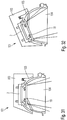
- Fig. 1
- eine Leuchte sowie einen Einbaurahmen, in den die Leuchte eingesetzt ist, gemäß einem ersten Ausführungsbeispiel, in einer perspektivischen Ansicht von einer Rückseite;
- Fig. 2
- die Leuchte der
Fig. 1 in einer perspektivischen Seitenansicht, wobei der Rahmen zur besseren Übersicht weggelassen ist; - Fig. 3
- einige zusammengebaute Bauteile der Leuchte der
Fig. 1 in einer perspektivischen Ansicht; - Fig. 4
- eine perspektivische Ansicht analog
Fig. 3 , wobei weitere Bauteile der Leuchte zur besseren Übersicht weggelassen sind; - Fig. 5
- die Leuchte der
Fig. 1 in einer perspektivischen Vorderansicht; - Fig. 6
- die Leuchte sowie den Einbaurahmen gemäß
Fig. 1 in einem Schnitt A-A, wie inFig. 1 angedeutet; - Fig. 7
- einen Kühlkörper der Leuchte der
Fig. 1 in einer perspektivischen Rückansicht; - Fig. 8
- den Kühlkörper aus
Fig. 7 in einer ersten Seitenansicht; - Fig. 9
- den Kühlkörper aus
Fig. 7 in einer zweiten Seitenansicht; - Fig. 10
- den Kühlkörper aus
Fig. 7 in einer perspektivischen Innenansicht; - Fig. 11
- einen Reflektor der Leuchte der
Fig. 1 in einer perspektivischen Rückansicht; - Fig. 12
- den Reflektor aus
Fig. 11 in einer Rückansicht; - Fig. 13
- den Reflektor aus
Fig. 11 in einem Schnitt B-B, wie inFig. 12 angedeutet; - Fig. 14
- den Reflektor aus
Fig. 11 in einer Seitenansicht; - Fig. 15
- ein Detail I des Reflektors, wie in
Fig. 14 angedeutet; - Fig. 16
- ein Zwischenelement der Leuchte der
Fig. 1 in einer perspektivischen Innenansicht; - Fig. 17
- das Zwischenelement aus
Fig. 16 in einer Rückansicht; - Fig. 18
- ein Detail II des Zwischenelements, wie in
Fig. 17 angedeutet; - Fig. 19
- das Zwischenelement aus
Fig. 16 in einem Schnitt C-C, wie inFig. 17 angedeutet; - Fig. 20
- eine Seitenansicht der Leuchte der
Fig. 1 , wobei der Kühlkörper eine erste Stellung in Bezug auf den Reflektor einnimmt; - Fig. 21
- die Leuchte im Zustand der
Fig. 20 in einem Mittelschnitt; - Fig. 22
- die Leuchte im Zustand der
Fig. 20 in einer Vorderansicht von einer Sichtseite; - Fig. 23
- eine Seitenansicht der Leuchte der
Fig. 2 , wobei der Kühlkörper im Vergleich mit seiner Stellung inFig. 20 verschwenkt ist und eine zweite Stellung in Bezug auf den Reflektor einnimmt; - Fig. 24
- die Leuchte im Zustand der
Fig. 23 in einem Mittelschnitt; - Fig. 25
- die Leuchte im Zustand der
Fig. 23 in einer Vorderansicht von einer Sichtseite; - Fig. 26
- eine Leuchte gemäß einer Variante des ersten Ausführungsbeispiels mit im Vergleich zu dem ersten Ausführungsbeispiel modifiziertem Kühlkörper, in einer Explosionsansicht;
- Fig. 27
- die Leuchte der
Fig. 26 perspektivisch von einer Rückseite her gesehen; - Fig. 28
- die Leuchte der
Fig. 26 in einer ersten Seitenansicht; - Fig. 29
- die Leuchte der
Fig. 26 in einer zweiten Seitenansicht; - Fig. 30
- die Leuchte der
Fig. 26 in einem Mittelschnitt D-D gemäßFig. 28 ; - Fig. 31
- eine Leuchte gemäß einem zweiten Ausführungsbeispiel in einem Mittelschnitt für eine erste Stellung eines Kühlkörpers; und
- Fig. 32
- die Leuchte der
Fig. 26 in einem Mittelschnitt für eine zweite Stellung des Kühlkörpers.
- Fig. 1
- a lamp and a mounting frame, in which the lamp is used, according to a first embodiment, in a perspective view from a rear side;
- Fig. 2
- the light of the
Fig. 1 in a perspective side view, the frame is omitted for clarity; - Fig. 3
- some assembled components of the luminaire
Fig. 1 in a perspective view; - Fig. 4
- a perspective view analog
Fig. 3 , wherein other components of the lamp are omitted for clarity; - Fig. 5
- the light of the
Fig. 1 in a perspective front view; - Fig. 6
- the luminaire and the mounting frame according to
Fig. 1 in a section AA, as inFig. 1 indicated; - Fig. 7
- a heat sink of the luminaire
Fig. 1 in a perspective rear view; - Fig. 8
- the heat sink off
Fig. 7 in a first side view; - Fig. 9
- the heat sink off
Fig. 7 in a second side view; - Fig. 10
- the heat sink off
Fig. 7 in a perspective interior view; - Fig. 11
- a reflector of the luminaire
Fig. 1 in a perspective rear view; - Fig. 12
- the reflector off
Fig. 11 in a rear view; - Fig. 13
- the reflector off
Fig. 11 in a section BB, as inFig. 12 indicated; - Fig. 14
- the reflector off
Fig. 11 in a side view; - Fig. 15
- a detail I of the reflector, as in
Fig. 14 indicated; - Fig. 16
- an intermediate element of the luminaire
Fig. 1 in a perspective interior view; - Fig. 17
- the intermediate element
Fig. 16 in a rear view; - Fig. 18
- a detail II of the intermediate element, as in
Fig. 17 indicated; - Fig. 19
- the intermediate element
Fig. 16 in a section CC, as inFig. 17 indicated; - Fig. 20
- a side view of the light of
Fig. 1 wherein the heat sink occupies a first position with respect to the reflector; - Fig. 21
- the light in the state of
Fig. 20 in a middle section; - Fig. 22
- the light in the state of
Fig. 20 in a front view from a visible side; - Fig. 23
- a side view of the light of
Fig. 2 , where the heat sink compared with its position inFig. 20 is pivoted and occupies a second position with respect to the reflector; - Fig. 24
- the light in the state of
Fig. 23 in a middle section; - Fig. 25
- the light in the state of
Fig. 23 in a front view from a visible side; - Fig. 26
- a lamp according to a variant of the first embodiment with in comparison to the first embodiment modified heat sink, in an exploded view;
- Fig. 27
- the light of the
Fig. 26 seen in perspective from a rear side; - Fig. 28
- the light of the
Fig. 26 in a first side view; - Fig. 29
- the light of the
Fig. 26 in a second side view; - Fig. 30
- the light of the
Fig. 26 in a middle section DD according toFig. 28 ; - Fig. 31
- a lamp according to a second embodiment in a central section for a first position of a heat sink; and
- Fig. 32
- the light of the
Fig. 26 in a central section for a second position of the heat sink.
Die beiliegenden Zeichnungen sollen ein weiteres Verständnis der Ausführungsformen der Erfindung vermitteln. Sie veranschaulichen Ausführungsformen und dienen im Zusammenhang mit der Beschreibung der Erklärung von Prinzipien und Konzepten der Erfindung. Andere Ausführungsformen und viele der genannten Vorteile ergeben sich im Hinblick auf die Zeichnungen. Die Elemente der Zeichnungen sind nicht notwendigerweise maßstabsgetreu zueinander gezeigt.The accompanying drawings are intended to provide further understanding of the embodiments of the invention. They illustrate embodiments and, together with the description, serve to explain principles and concepts of the invention. Other embodiments and many of the stated advantages will become apparent with reference to the drawings. The elements of the drawings are not necessarily shown to scale to each other.
In den Figuren der Zeichnungen sind gleiche, funktionsgleiche und gleich wirkende Elemente, Merkmale und Komponenten - sofern nichts anderes ausgeführt ist -jeweils mit denselben Bezugszeichen versehen.In the figures of the drawings, identical, functionally identical and identically acting elements, features and components - unless otherwise stated - each provided with the same reference numerals.
Eine Leuchte 1 gemäß einem ersten Ausführungsbeispiel, sowie Bauteile der Leuchte 1, sind in den
Die Leuchte 1 weist eine Lichterzeugungseinrichtung 2, einen helmartigen Kühlkörper 3, einen zumindest abschnittsweise kuppelartigen Reflektor 4 und ein Zwischenelement 5 auf. Der Kühlkörper 3 übergreift jeweils den Reflektor 4 und das Zwischenelement 5, wodurch der Reflektor 4 und das Zwischenelement 5 jeweils mit einem Abschnitt in einem Innenbereich 24 des Kühlkörpers 3 aufgenommen sind, siehe
Die Lichterzeugungseinrichtung 2 umfasst eine LED-Einrichtung 23 mit einer oder mehreren LEDs, welche das von der Leuchte 1 abzustrahlende Licht bereitstellen.
Die Lichterzeugungseinrichtung 2 ist derart angeordnet, dass sie im Betrieb Licht in einen Innenraum 7 des Reflektors 4 abgeben kann. Dies soll nachstehend erläutert werden.The
Die Leuchte 1 weist eine Linse 19 auf, welche dafür eingerichtet und angeordnet ist, um das von der Lichterzeugungseinrichtung 2 bereitgestellte Licht zu lenken und/oder zu bündeln. Die Linse 19 ist hierzu, siehe
Das Zwischenelement 5, welches nachstehend noch näher beschrieben werden wird, weist eine im Wesentlichen kreisrunde Aussparung 14 in Gestalt einer Durchgangsöffnung auf, deren Form und Durchmesser an die Form und den Durchmesser der Linse 19 angepasst sind. Ein Abschnitt der Linse 19 ist in der Aussparung 14 aufgenommen. Somit bildet die Aussparung 14 einen Aufnahmebereich 20 für die Linse 19.The
Der Durchgang 16 ist hinsichtlich seiner Fläche größer als die Aussparung 14 des Zwischenelements 5. In
Der Kühlkörper 3 ist um eine Schwenkachse 6, die durch zwei radial nach außen abstehende Schwenkzapfen 17 des Reflektors 4 definiert ist, relativ zu dem Reflektor 4 schwenkbar mit diesem gekoppelt. Auf diese Weise wird ein Verschwenken des Kühlkörpers 3 relativ zu dem Reflektor 4 innerhalb eines vordefinierten Schwenkbereichs 15 ermöglicht, wobei bei dem gezeigten ersten Ausführungsbeispiel der Schwenkbereich 15 um die Schwenkachse 6 als ein Winkelbereich von etwa 30 Grad gegenüber der Mittelachse 22, siehe
Eine gezielte Ausrichtung eines von der Leuchte 1 erzeugten Lichtkegels wird durch die Verstellung des Kühlkörpers 3 relativ zu dem Reflektor 4 um die Schwenkachse 6 möglich. Der Kühlkörper 3 wird hierbei gemeinsam mit dem Zwischenelement 5, der Linse 19 und der Lichterzeugungseinrichtung 2 verschwenkt. Eine erste Endstellung des Kühlkörpers 3 ist in den
Aus
Mittels der Kombination der Schwenkbarkeit des Kühlkörpers 3 um die Schwenkachse 6 und der Verdrehbarkeit des Reflektors 4, und somit der Leuchte 1, um die Mittelachse 22 wird eine flexible und vielseitige Ausrichtung des von der Leuchte 1 erzeugten Lichtes erreicht. Die Mittelachse 22 und die Schwenkachse 6 stehen hierbei im Wesentlichen senkrecht zueinander, wobei bei einem im Wesentlichen horizontalen Einbau des Rahmens 21 in die Decke die Schwenkachse 6 horizontal und die Mittelachse 22 vertikal ausgerichtet sind. Die Mittelachse 22 steht hierbei insbesondere senkrecht zu einer nicht näher dargestellten Einbauebene, die zum Beispiel der Deckenebene entspricht. Das Verdrehen der Leuchte 1 um die Mittelachse 22 stört das Deckenbild nicht.By means of the combination of the pivoting of the
Der Kühlkörper 3 weist, siehe zum Beispiel
Das Einrasten der Leuchte 1 in den Rahmen 21 wird mittels an dem Reflektor 4 angeordneter Rasteinrichtungen 35 ermöglicht. Bei der Leuchte 1 sind die Rasteinrichtungen 35 jeweils als eine federbelastete und radial nach außen weisende Kugel ausgebildet. Die Rasteinrichtungen 35 können auch als Kugelschnapper bezeichnet werden. Die Kugeln sind jeweils in einer geeigneten Aufnahme 36 an dem Reflektor 4 aufgenommen. Drei Aufnahmen 36 für Kugeln der Rasteinrichtungen 35 sind in einem Abstand entsprechend jeweils einem Winkel W von 120 Grad um die Mittelachse 22 am Außenumfang des Reflektors 4 angeordnet, siehe insbesondere
Das mit einer kappen- oder schalenartigen Form ausgebildete Zwischenelement 5 ist in den
Der Reflektor 4, der in den
Der Kühlkörper 3 ist, siehe beispielsweise
Ferner ist zwischen dem Kühlkörper 3 und dem Zwischenelement 5 auf jede der zapfenförmigen Führungseinrichtungen 38 eine jeweils als eine Druckfeder ausgebildete Federeinrichtung 12 aufgesetzt. Siehe beispielsweise
Es sei darauf hingewiesen, dass die
Die Federeinrichtungen 12 beaufschlagen das Zwischenelement 5 mit einer Federkraft F parallel zu der Richtung V, siehe zum Beispiel
Unter der Wirkung der Federeinrichtungen 12 werden die Zahnungen 8 gegen die Zahnungen 10 gedrückt und greifen ineinander ein. Die Gestaltung der Zahnungen 8 ist derart getroffen, dass die Zahnung 8 des kürzer ausgeführten ersten Abschnitts 9 entlang des Kreisbogens 13 an verschiedenen Stellen in die Zahnung 10 des länger ausgebildeten zweiten Abschnitts 11 eingreifen kann. Die Zahnungen 8 und 10 sind also aufeinander abgestimmt ausgebildet, um einen derartigen Eingriff realisieren zu können.Under the action of the spring means 12, the serrations 8 are pressed against the
Der Eingriff der Zahnungen 8 und 10 ineinander wirkt einem Verschwenken des Kühlkörpers 3, und somit auch der Lichterzeugungseinrichtung 2, um die Schwenkachse 6 relativ zu dem Reflektor 4 entgegen. Eine einmal eingestellte Schwenkstellung des Kühlkörpers 3 und somit des erzeugten Lichtkegels bleibt auf diese Weise zuverlässig und präzise erhalten.The engagement of the
Die Leuchte 1 ermöglicht es, den Kühlkörper 3 und damit die Ausrichtung des abgegebenen Lichtes zu verändern, ohne dass die Leuchte 1 aus dem Rahmen 21 herausgenommen werden muss. Eine Bedienerperson drückt hierzu von der Sichtseite S der Leuchte 1 her, siehe zum Beispiel
Die Linse 19 wird hierbei also in Richtung zu dem Kühlkörper 3 hin gedrückt. In diesem Zustand kann der Kühlkörper 3 zusammen mit der Lichterzeugungseinrichtung 2, dem Zwischenelement 5 und der Linse 19 um die Schwenkachse 6 verschwenkt werden. In der gewünschten Winkelstellung des Kühlkörpers 3 nimmt die Bedienerperson den Druck von der Linse 19 weg, wodurch der Eingriff der Zahnungen 8 und 10 wieder hergestellt wird und die gewünschte Ausrichtung des Kühlkörpers 3 fixiert wird. Unter der Wirkung der Federeinrichtungen 12 kann also der Kühlkörper 3 in jeder gewünschten der im Verschwenkbereich 15 möglichen Stellungen desselben gehalten werden. Die Linse 19 kann beispielsweise in der Aussparung 14 an dem Zwischenelement 5 befestigt sein.In this case, the
Auch ein Verstellen um die Mittelachse 22 kann erfolgen, ohne die Leuchte 1 aus dem Rahmen 21 herausnehmen zu müssen. Somit lässt sich die Leuchte 1 ohne die Notwendigkeit einer Demontage vielseitig justieren.An adjustment about the
In einer Richtung parallel zu der Schwenkachse 6 entspricht eine Abmessung des Durchgangs 16 im Reflektor 4 im Wesentlichen einem Durchmesser der Aussparung 14 im Zwischenelement. Durch die Aussparung 14 ragt die Linse 19, wodurch mit Hilfe der Linse 19 gelenktes und/oder gebündeltes Licht in den Innenraum 7 des Reflektors 4 abgegeben werden kann. Beim Verschwenken um die Schwenkachse 6 bewegt sich das Zwischenelement 5 mit dem Kühlkörper 3 mit und verschiebt sich im Bereich der Außenseite 41 des Reflektors 4 in der Weise, dass außerhalb des Bereichs der Linse 19 der Durchgang 16 stets im Wesentlichen abgedeckt bleibt. Siehe beispielsweise
Für jede Schwenkstellung des Kühlkörpers 3 relativ zu dem Reflektor 4 innerhalb des Schwenkbereichs 15 kann somit Licht von der Lichterzeugungseinrichtung 2 in den Innenraum 7 abgegeben werden, während ein unerwünschter Lichtaustritt auf die Rückseite des Reflektors 4 vermieden wird. Somit werden auch mit einem derartigen Lichtaustritt verbundene Lichtverluste vermieden. Das Zwischenelement 5 wirkt somit als ein auf der Reflektoraußenseite 41 verschiebbares Abdeckelement, das sich mit dem Kühlkörper 3 beim Verschwenken um die Achse 6 mitbewegt. Ein Bereich 25 des Durchgangs 16, durch den in einer Schwenkstellung des Kühlkörpers 3 jeweils die Linse 19 ragt, wird für die Lichtabgabe in den Innenraum 7 genutzt, während ein verbleibender Bereich 26, oder im Fall von Zwischenstellung verbleibende Bereiche, des Durchgangs 16 außerhalb des Bereichs 25 in jeder Schwenkstellung des Kühlkörpers 3 im Schwenkbereich 15 durch das Zwischenelement 5 im Wesentlichen abgedeckt wird/werden. Auf diese Weise entsteht, für alle möglichen Stellungen des Kühlkörpers 3, beim Verschwenken des Kühlkörpers 3 im Wesentlichen kein von der Sichtseite S sichtbarer Spalt an der Rückseite des Reflektors 4. Während
Eine Leuchte 1 gemäß einer Variante des ersten Ausführungsbeispiels mit einem modifizierten Kühlkörper 3 zeigen die
Eine Leuchte 101 mit einer Lichterzeugungseinrichtung 2, einem Kühlkörper 103, einem Reflektor 104 und einem Zwischenelement 105 gemäß einem zweiten Ausführungsbeispiel zeigen die
Bei den vorstehend beschriebenen Ausführungsbeispiel ist der Kühlkörper 3, 103 aus einem Metallmaterial gebildet, zum Beispiel druckgegossen. Der Reflektor 4, 104 und das Zwischenelement 5, 105 sind jeweils aus einem Kunststoffmaterial gefertigt, zum Beispiel spritzgegossen. Beispielsweise können der Reflektor 4, 104 und das Zwischenelement 5, 105 aus einem Polycarbonat gefertigt sein. Der Reflektor 4, 104, und falls gewünscht auch das Zwischenelement 5, 105, können in einer Reihe unterschiedlicher Farben, beispielsweise schwarz, weiß, kupferfarben, chromfarben oder goldfarben, bereitgestellt werden. Der Reflektor 4, 104, und falls gewünscht auch das Zwischenelement 5, 105, können vakuumbeschichtet sein.In the embodiment described above, the
Obwohl die vorliegende Erfindung anhand bevorzugter Ausführungsbeispiele vorstehend vollständig beschrieben wurde, ist sie darauf nicht beschränkt, sondern auf vielfältige Art und Weise modifizierbar.Although the present invention has been fully described above with reference to preferred embodiments, it is not limited thereto but is modifiable in a variety of ways.
- 11
- Leuchtelamp
- 22
- LichterzeugungseinrichtungLight fixture
- 33
- Kühlkörperheatsink
- 44
- Reflektorreflector
- 55
- Zwischenelementintermediate element
- 66
- Schwenkachseswivel axis
- 77
- Innenraum (Reflektor)Interior (reflector)
- 88th
- ZahnungPerforation
- 99
- erster Abschnittfirst section
- 1010
- ZahnungPerforation
- 1111
- zweiter Abschnittsecond part
- 1212
- Federeinrichtungspring means
- 1313
- Bogenarc
- 1414
- Aussparung (Zwischenelement)Recess (intermediate element)
- 1515
- Schwenkbereichswivel range
- 1616
- Durchgang (Reflektor)Passage (reflector)
- 1717
- Schwenkzapfen (Reflektor)Pivot pin (reflector)
- 1818
- Ausnehmung (Kühlkörper)Recess (heat sink)
- 1919
- Linselens
- 2020
- Aufnahmebereich (Zwischenelement)Receiving area (intermediate element)
- 2121
- Rahmenframe
- 2222
- Mittelachse (Reflektor)Central axis (reflector)
- 2323
- LED-EinrichtungLED device
- 2424
- Innenbereich (Kühlkörper)Interior (heat sink)
- 2525
- Bereich (Durchgang)Area (passage)
- 2626
- Bereich (Durchgang)Area (passage)
- 2727
- Befestigungseinrichtungfastening device
- 2828
- Rippen (Kühlkörper)Ribs (heat sink)
- 2929
- Stirnwand (Kühlkörper)End wall (heat sink)
- 3030
- Umfangswand (Kühlkörper)Peripheral wall (heat sink)
- 3131
- Ausschnitt (Umfangswand)Cutout (peripheral wall)
- 3232
- Montageflächemounting surface
- 3333
- schalenartiger Abschnitt (Reflektor)dish-like section (reflector)
- 3434
- Außenrand (Umfangswand)Outer edge (peripheral wall)
- 3535
- Rasteinrichtunglocking device
- 3636
- Aufnahmeadmission
- 3737
- Symmetrieachse (Zwischenelement)Symmetry axis (intermediate element)
- 3838
- Führungseinrichtung (Zwischenelement)Guide device (intermediate element)
- 38'38 '
- Stufestep
- 38"38 "
- Außenoberflächeouter surface
- 38'"38 ''
- Längsnutlongitudinal groove
- 3939
- Symmetrieachse (Reflektor)Symmetry axis (reflector)
- 4040
- Führungseinrichtung (Kühlkörper)Guide device (heat sink)
- 4141
- Außenseite (Reflektor)Outside (reflector)
- 4242
- Öffnungopening
- 101101
- Leuchtelamp
- 103103
- Kühlkörperheatsink
- 104104
- Reflektorreflector
- 105105
- Zwischenelementintermediate element
- FF
- Federkraftspring force
- SS
- SichtseiteMain page
- VV
- Verschieberichtungdisplacement direction
- WW
- Winkelcorner
- W'W '
- Winkelcorner
- W1W1
- Winkelcorner
- W2W2
- Winkelcorner
Claims (16)
mit einer Lichterzeugungseinrichtung (2), einem Kühlkörper (3; 103), einem Reflektor (4; 104) und einem Zwischenelement (5; 105);
wobei der Kühlkörper (3; 103) um eine Schwenkachse (6) relativ zu dem Reflektor (4; 104) schwenkbar mit dem Reflektor (4; 104) gekoppelt ist;
wobei die Lichterzeugungseinrichtung (2) an dem Kühlkörper (3; 103) derart angeordnet ist, dass von der Lichterzeugungseinrichtung (2) Licht in einen Innenraum (7) des Reflektors (4; 104) abgegeben werden kann;
wobei das Zwischenelement (5; 105) an dem Kühlkörper (3; 103) relativ zu dem Kühlkörper (3; 103) verschiebbar gelagert ist;
wobei das Zwischenelement (5; 105) mindestens einen ersten mit einer Zahnung (8) versehenen Abschnitt (9) aufweist und der Reflektor (4; 104) mindestens einen zweiten mit einer Zahnung (10) versehenen Abschnitt (11) aufweist; und
wobei ein Eingriff der Zahnungen (8, 10) der ersten und zweiten Abschnitte (9, 11) ineinander einem Verschwenken des Kühlkörpers (3; 103) relativ zu dem Reflektor (4; 104) um die Schwenkachse (6) entgegenwirkt und für ein Verschwenken des Kühlkörpers (3; 103) relativ zu dem Reflektor (4; 104) um die Schwenkachse (6) die Zahnungen (8, 10) der ersten und zweiten Abschnitte (9, 11) außer Eingriff bringbar sind.Luminaire (1; 101),
with a light generating device (2), a heat sink (3; 103), a reflector (4; 104) and an intermediate element (5; 105);
wherein the heat sink (3; 103) is pivotally coupled to the reflector (4; 104) about a pivot axis (6) relative to the reflector (4; 104);
wherein the light generating means (2) is arranged on the heat sink (3; 103) such that light can be emitted from the light generating means (2) into an interior space (7) of the reflector (4; 104);
wherein the intermediate element (5; 105) is displaceably mounted on the heat sink (3; 103) relative to the heat sink (3; 103);
wherein the intermediate element (5; 105) has at least one first section (9) provided with a toothing (8) and the reflector (4; 104) has at least one second section (11) provided with a toothing (10); and
wherein engagement of the serrations (8, 10) of the first and second sections (9, 11) counteracts pivoting of the heat sink (3; 103) relative to the reflector (4; 104) about the pivot axis (6) and for pivoting the toothings (8, 10) of the first and second sections (9, 11) can be brought out of engagement with the heat sink (3; 103) relative to the reflector (4; 104) about the pivot axis (6).
dadurch gekennzeichnet, dass das Zwischenelement (5; 105) in einer Richtung (V), längs der das Zwischenelement (5; 105) relativ zu dem Kühlkörper (3; 103) verschiebbar ist, in Bezug auf den Kühlkörper (3; 103) mit einer Federkraft (F) beaufschlagt ist.Luminaire according to claim 1,
characterized in that the intermediate member (5; 105) is movable with respect to the heat sink (3; 103) in a direction (V) along which the intermediate member (5; 105) is slidable relative to the heat sink (3; a spring force (F) is acted upon.
dadurch gekennzeichnet, dass die Leuchte (1; 101) mindestens eine Federeinrichtung (12) aufweist, welche das Zwischenelement (5; 105) in Bezug auf den Kühlkörper (3; 103) derart mit einer Federkraft (F) beaufschlagt, dass die Zahnung (8) des ersten Abschnitts (9) gegen die Zahnung (10) des zweiten Abschnitts (11) gedrückt wird.Luminaire according to claim 1 or 2,
characterized in that the lamp (1; 101) has at least one spring device (12) which acts on the intermediate element (5; 105) with a spring force (F) in relation to the heat sink (3; 8) of the first section (9) is pressed against the toothing (10) of the second section (11).
dadurch gekennzeichnet, dass zumindest die Zahnung (10) des zweiten Abschnitts (11) entlang eines Bogens (13), insbesondere entlang eines Kreisbogens, angeordnet ist.Luminaire according to at least one of the preceding claims,
characterized in that at least the toothing (10) of the second portion (11) along an arc (13), in particular along a circular arc, is arranged.
dadurch gekennzeichnet, dass das Zwischenelement (5; 105) als eine zumindest bereichsweise kappen- oder schalenartige Komponente mit einer Aussparung (14) ausgebildet ist.Luminaire according to at least one of the preceding claims,
characterized in that the intermediate element (5; 105) is formed as an at least partially cap-like or shell-like component with a recess (14).
dadurch gekennzeichnet, dass der Kühlkörper (3; 103) relativ zu dem Reflektor (4; 104) innerhalb eines vordefinierten Schwenkbereichs (15) verschwenkbar mit dem Reflektor (4; 104) gekoppelt ist und der Reflektor (4; 104) rückseitig einen Durchgang (16) aufweist, der die Abgabe von Licht durch die Lichterzeugungseinrichtung (2) in den Innenraum (7) des Reflektors (4; 104) für Stellungen des Kühlkörpers (3; 103) relativ zu dem Reflektor (4; 104) innerhalb des Schwenkbereichs (15) ermöglicht, und dass das Zwischenelement (5; 105) als ein Abdeckelement ausgebildet ist, welches in den Stellungen des Kühlkörpers (3; 103) relativ zu dem Reflektor (4; 104) innerhalb des Schwenkbereichs (15) den Durchgang (16) des Reflektors (4; 104) außerhalb eines Bereichs (25) des Durchgangs (16), der in der Stellung des Kühlkörpers (3; 103) im Betrieb der Lichterzeugungseinrichtung (2) für die Abgabe des Lichtes in den Innenraum (7) des Reflektors (4; 104) genutzt wird, jeweils im Wesentlichen abdeckt.Luminaire according to at least one of the preceding claims,
characterized in that the heat sink (3; 103) is pivotably coupled to the reflector (4; 104) relative to the reflector (4; 104) within a predefined pivoting area (15) and the reflector (4; 16), which controls the emission of light by the light generating device (2) into the interior (7) of the reflector (4; 104) for positions of the heat sink (3; 103) relative to the reflector (4; 15), and in that the intermediate element (5; 105) is designed as a cover element which, in the positions of the heat sink (3; 103) relative to the reflector (4; 104) within the pivoting region (15), the passage (16). outside of a region (25) of the passage (16) which is in the position of the heat sink (3; 103) during operation of the light generating device (2) for emitting the light into the interior (7) of the reflector (4; 104) is used, each essentially covers.
dadurch gekennzeichnet, dass der Kühlkörper (3; 103) helmartig ausgebildet ist und den Reflektor (4; 104) und das Zwischenelement (5; 105) jeweils übergreift.Luminaire according to at least one of the preceding claims,
characterized in that the cooling body (3; 103) is designed like a helmet and engages over the reflector (4; 104) and the intermediate element (5; 105) in each case.
dadurch gekennzeichnet, dass der Reflektor (4) Schwenkzapfen (17) aufweist, welche die Schwenkachse (6) definieren, und dass der Kühlkörper (3) den Schwenkzapfen (17) jeweils zugeordnete Ausnehmungen (18) aufweist, wobei der Kühlkörper (3) auf den Reflektor (4) derart aufgerastet ist, dass die Schwenkzapfen (17) jeweils in einer der Ausnehmungen (18) schwenkbar aufgenommen sind.Luminaire according to at least one of the preceding claims,
characterized in that the reflector (4) pivot pin (17) which define the pivot axis (6), and that the cooling body (3) the pivot pin (17) respectively associated recesses (18), wherein the heat sink (3) the reflector (4) is latched in such a way that the pivot pins (17) in each case in one of the recesses (18) are pivotally received.
dadurch gekennzeichnet, dass die Leuchte (1; 101) ferner eine Linse (19) aufweist, welche dafür eingerichtet und angeordnet ist, um das von der Lichterzeugungseinrichtung (2) bereitgestellte Licht zu lenken und/oder zu bündeln, und dass das Zwischenelement (5; 105) einen an eine Größe und Form der Linse (19) angepassten, vorzugsweise kreisrunden, Aufnahmebereich (20) aufweist, in dem die Linse (19) mindestens abschnittsweise aufgenommen ist.Luminaire according to at least one of the preceding claims,
characterized in that the lamp (1; 101) further comprises a lens (19) arranged and arranged to be the one from the light generating means (2) to direct and / or bundle the light provided, and in that the intermediate element (5; 105) has a preferably circular receiving area (20) adapted to a size and shape of the lens (19), in which the lens (19 ) is recorded at least in sections.
dadurch gekennzeichnet, dass die Linse (19) derart mit dem Zwischenelement (5; 105) gekoppelt ist, dass von einer Bedienerperson durch Drücken auf die Linse (19) von einer Sichtseite (S) der Leuchte (1; 101) her die Zahnungen (8, 10) der ersten und zweiten Abschnitte (9, 11) für das Verschwenken des Kühlkörpers (3; 103) relativ zu dem Reflektor (4; 104) außer Eingriff bringbar sind.Luminaire according to claim 9,
characterized in that the lens (19) is coupled to the intermediate element (5; 105) in such a way that the teeth (1; 101) from an operator person press the lens (19) from a visible side (S) of the luminaire (1; 8, 10) of the first and second sections (9, 11) for pivoting the heat sink (3, 103) relative to the reflector (4, 104) are disengageable.
dadurch gekennzeichnet, dass ferner ein Rahmen (21) vorgesehen ist, in den der Reflektor (4; 104) derart einrastbar ist, dass der eingerastete Reflektor (4; 104) um eine Mittelachse (22) des Reflektors (4; 104) relativ zu dem Rahmen (21) verdrehbar ist.Luminaire according to at least one of the preceding claims,
characterized in that there is further provided a frame (21) into which the reflector (4; 104) can be latched such that the latched reflector (4; 104) extends about a central axis (22) of the reflector (4; 104) relative to the frame (21) is rotatable.
dadurch gekennzeichnet, dass die Schwenkachse (6), um die der Kühlkörper (3; 103) relativ zu dem Reflektor (4; 104) schwenkbar mit dem Reflektor (4; 104) gekoppelt ist, im Wesentlichen normal zu der Mittelachse (22), um die der Reflektor (4; 104) in dem Rahmen (21) verdrehbar ist, angeordnet ist.Luminaire according to claim 11,
characterized in that the pivot axis (6) about which the heat sink (3; 103) is pivotally coupled to the reflector (4; 104) relative to the reflector (4; 104) is substantially normal to the central axis (22), around which the reflector (4; 104) is rotatable in the frame (21) is arranged.
dadurch gekennzeichnet, dass der Kühlkörper (3; 103) mit einem Metallmaterial gebildet ist und dass der Reflektor (4; 104) und das Zwischenelement (5; 105) jeweils mit einem Kunststoffmaterial gebildet sind.Luminaire according to at least one of the preceding claims,
characterized in that the heat sink (3; 103) is formed with a metal material, and that the reflector (4; 104) and the intermediate element (5; 105) are each formed with a plastic material.
dadurch gekennzeichnet, dass die Lichterzeugungseinrichtung (2) mit einer LED-Einrichtung (23) ausgebildet ist, welche an dem Kühlkörper (3; 103) angeordnet ist.Luminaire according to at least one of the preceding claims,
characterized in that the light generating device (2) is formed with an LED device (23) which is arranged on the heat sink (3; 103).
mit einer Lichterzeugungseinrichtung (2), einem zumindest abschnittsweise kuppelartigen Reflektor (4; 104), und einem helmartig ausgebildeten Kühlkörper (3; 103); wobei der Kühlkörper (3; 103) um eine Schwenkachse (6) relativ zu dem Reflektor (4; 104) schwenkbar mit dem Reflektor (4; 104) gekoppelt ist;
wobei die Lichterzeugungseinrichtung (2) an dem Kühlkörper (3; 103) derart angeordnet ist, dass von der Lichterzeugungseinrichtung (2) Licht in einen Innenraum (7) des Reflektors (4; 104) abgegeben werden kann; und
wobei der Kühlkörper (3; 103) den Reflektor (4; 104) übergreift und hierdurch der Reflektor (4; 104) abschnittsweise in einem Innenbereich (24) des Kühlkörpers (3; 103) aufgenommen ist.Luminaire (1; 101),
with a light generating device (2), an at least partially dome-shaped reflector (4, 104), and a heat sink (3, 103) of helical design; wherein the heat sink (3; 103) is pivotally coupled to the reflector (4; 104) about a pivot axis (6) relative to the reflector (4; 104);
wherein the light generating means (2) is arranged on the heat sink (3; 103) such that light can be emitted from the light generating means (2) into an interior space (7) of the reflector (4; 104); and
wherein the heat sink (3; 103) engages over the reflector (4; 104) and as a result the reflector (4; 104) is received in sections in an interior region (24) of the heat sink (3;
dadurch gekennzeichnet, dass der Kühlkörper (3; 103) relativ zu dem Reflektor (4; 104) innerhalb eines vordefinierten Schwenkbereichs (15) verschwenkbar mit dem Reflektor (4; 104) gekoppelt ist und der Reflektor (4; 104) rückseitig einen Durchgang (16) aufweist, der die Abgabe von Licht durch die Lichterzeugungseinrichtung (2) in den Innenraum (7) des Reflektors (4; 104) für Stellungen des Kühlkörpers (3; 103) relativ zu dem Reflektor (4; 104) innerhalb des Schwenkbereichs (15) ermöglicht, und dass die Leuchte (1; 101) ein Zwischenelement (5; 105) aufweist, das als ein Abdeckelement ausgebildet ist, welches in den Stellungen des Kühlkörpers (3; 103) relativ zu dem Reflektor (4; 104) innerhalb des Schwenkbereichs (15) den Durchgang (16) des Reflektors (4; 104) außerhalb eines Bereichs (25) des Durchgangs (16), der in der Stellung des Kühlkörpers (3; 103) im Betrieb der Lichterzeugungseinrichtung (2) für die Abgabe des Lichtes in den Innenraum (7) des Reflektors (4; 104) genutzt wird, jeweils im Wesentlichen abdeckt.Luminaire according to claim 15,
characterized in that the heat sink (3; 103) is pivotably coupled to the reflector (4; 104) relative to the reflector (4; 104) within a predefined pivoting area (15) and the reflector (4; 16), which controls the emission of light by the light generating device (2) into the interior (7) of the reflector (4; 104) for positions of the heat sink (3; 103) relative to the reflector (4; 15), and in that the luminaire (1; 101) has an intermediate element (5; 105) which is designed as a cover element which is in the positions of the heat sink (3; 103) relative to the reflector (4; 104) within of the pivoting region (15) the passage (16) of the reflector (4; 104) outside a region (25) of the passage (16), in the position of the heat sink (3; 103) in the operation of the light generating means (2) for the delivery of the light in the interior (7) of the reflector (4; 104) gen is used, each substantially covers.
Priority Applications (1)
| Application Number | Priority Date | Filing Date | Title |
|---|---|---|---|
| PL19160428T PL3534059T3 (en) | 2018-03-02 | 2019-03-04 | Luminaire |
Applications Claiming Priority (1)
| Application Number | Priority Date | Filing Date | Title |
|---|---|---|---|
| DE102018001652.9A DE102018001652B4 (en) | 2018-03-02 | 2018-03-02 | lamp |
Publications (3)
| Publication Number | Publication Date |
|---|---|
| EP3534059A2 true EP3534059A2 (en) | 2019-09-04 |
| EP3534059A3 EP3534059A3 (en) | 2019-11-13 |
| EP3534059B1 EP3534059B1 (en) | 2020-12-09 |
Family
ID=65685197
Family Applications (1)
| Application Number | Title | Priority Date | Filing Date |
|---|---|---|---|
| EP19160428.9A Active EP3534059B1 (en) | 2018-03-02 | 2019-03-04 | Luminaire |
Country Status (5)
| Country | Link |
|---|---|
| US (1) | US10627085B2 (en) |
| EP (1) | EP3534059B1 (en) |
| AT (1) | AT520986B1 (en) |
| DE (1) | DE102018001652B4 (en) |
| PL (1) | PL3534059T3 (en) |
Families Citing this family (4)
| Publication number | Priority date | Publication date | Assignee | Title |
|---|---|---|---|---|
| US11215332B2 (en) * | 2019-05-02 | 2022-01-04 | Intense Lighting, Inc. | Lighting fixture having an adjustable optic system |
| US10962203B1 (en) | 2020-03-30 | 2021-03-30 | Electronic Theatre Controls, Inc. | Adjustable light fixture |
| US11739922B2 (en) | 2020-05-11 | 2023-08-29 | Wangs Alliance Corporation | Fixtures, power and control systems for same |
| US11802682B1 (en) | 2022-08-29 | 2023-10-31 | Wangs Alliance Corporation | Modular articulating lighting |
Family Cites Families (8)
| Publication number | Priority date | Publication date | Assignee | Title |
|---|---|---|---|---|
| DE19615639B4 (en) | 1996-04-21 | 2009-05-07 | Acl Lichttechnik Gmbh | recessed light |
| DE20313905U1 (en) | 2003-09-04 | 2005-01-05 | Erco Leuchten Gmbh | Lighting unit fitted to e.g. wall or ceiling, and based on light-emitting diodes has optical coupling section transmitting light by multiple internal reflection |
| US7934860B2 (en) * | 2009-04-03 | 2011-05-03 | Frank Tsao | Lighting fixture with angle adjustment arrangement |
| DE102009057764A1 (en) | 2009-10-13 | 2011-04-14 | Erco Gmbh | Module construction system for a recessed luminaire |
| JP6254069B2 (en) | 2014-11-05 | 2017-12-27 | ミネベアミツミ株式会社 | Angle adjusting device and lighting device including the angle adjusting device |
| EP3217071B1 (en) * | 2016-03-11 | 2018-06-27 | Prolicht GmbH | Built-in spotlight for installation in a ceiling or attachment to ceilings |
| US9735083B1 (en) * | 2016-04-18 | 2017-08-15 | International Business Machines Corporation | Adjustable heat sink fin spacing |
| US10436434B2 (en) * | 2016-04-26 | 2019-10-08 | Lighting Science Group Corporation | Gimbal luminaire |
-
2018
- 2018-03-02 DE DE102018001652.9A patent/DE102018001652B4/en not_active Expired - Fee Related
- 2018-04-04 AT ATA50270/2018A patent/AT520986B1/en active
-
2019
- 2019-03-04 PL PL19160428T patent/PL3534059T3/en unknown
- 2019-03-04 US US16/291,397 patent/US10627085B2/en active Active
- 2019-03-04 EP EP19160428.9A patent/EP3534059B1/en active Active
Also Published As
| Publication number | Publication date |
|---|---|
| US20190271456A1 (en) | 2019-09-05 |
| AT520986B1 (en) | 2022-09-15 |
| US10627085B2 (en) | 2020-04-21 |
| AT520986A2 (en) | 2019-09-15 |
| DE102018001652A1 (en) | 2019-09-05 |
| AT520986A3 (en) | 2020-06-15 |
| EP3534059B1 (en) | 2020-12-09 |
| DE102018001652B4 (en) | 2019-10-02 |
| PL3534059T3 (en) | 2021-07-26 |
| EP3534059A3 (en) | 2019-11-13 |
Similar Documents
| Publication | Publication Date | Title |
|---|---|---|
| EP3534059A2 (en) | Luminaire | |
| EP2238387B1 (en) | Led luminaire having adjustable light source | |
| EP2314912B1 (en) | LED lamp with infinitely adjustable emission angle | |
| DD274872B5 (en) | POLARIZED LIGHT EMITTING TREATMENT LIGHT FOR BIOSTIMULATION | |
| EP2322847B1 (en) | Variable LED downlight | |
| DE102010003123A1 (en) | Lamp with reflector means and reflector element | |
| DE202015106256U1 (en) | Blendarme lighting technology | |
| EP0638764B2 (en) | Indoor lamp for mainly direct lighting | |
| EP3686480A1 (en) | Light emitting assembly with variable light emission characteristics | |
| DE202008006321U1 (en) | Adjustable lamp unit | |
| EP2085684B1 (en) | Lamp with self-supporting reflector unit | |
| DE102013213782A1 (en) | Semiconductor lamp for a vehicle light | |
| DE102010013654B4 (en) | Luminaire with displaceable socket holder | |
| DE202011051015U1 (en) | recessed light | |
| EP4208668A1 (en) | Luminaire for generating direct lighting and indirect lighting | |
| EP1567804B1 (en) | Reflector arrangement comprising successively arranged illumination means | |
| DE202016101553U1 (en) | Recessed luminaire with swiveling light source | |
| DE202022102261U1 (en) | Panel light with rear (secondary) lighting | |
| DE102010013655B4 (en) | Luminaire with led holder | |
| EP2518388B1 (en) | Lamp | |
| EP2994690B1 (en) | Light fixture with a housing having a plurality of light-emitting openings | |
| WO2009027012A1 (en) | Lighting unit comprising a lighting element formed by a plurality of lamps | |
| DE2314935A1 (en) | SPOTLIGHT | |
| DE102011082533A1 (en) | Flat lamp i.e. LED flat lamp, for use in mechanical engineering applications, has reflector arranged on lighting unit such that light of LEDs at portion of circuit board is bundled, so that regions are formed with different light intensity | |
| AT513703A1 (en) | Downlight |
Legal Events
| Date | Code | Title | Description |
|---|---|---|---|
| PUAI | Public reference made under article 153(3) epc to a published international application that has entered the european phase |
Free format text: ORIGINAL CODE: 0009012 |
|
| STAA | Information on the status of an ep patent application or granted ep patent |
Free format text: STATUS: THE APPLICATION HAS BEEN PUBLISHED |
|
| AK | Designated contracting states |
Kind code of ref document: A2 Designated state(s): AL AT BE BG CH CY CZ DE DK EE ES FI FR GB GR HR HU IE IS IT LI LT LU LV MC MK MT NL NO PL PT RO RS SE SI SK SM TR |
|
| AX | Request for extension of the european patent |
Extension state: BA ME |
|
| PUAL | Search report despatched |
Free format text: ORIGINAL CODE: 0009013 |
|
| AK | Designated contracting states |
Kind code of ref document: A3 Designated state(s): AL AT BE BG CH CY CZ DE DK EE ES FI FR GB GR HR HU IE IS IT LI LT LU LV MC MK MT NL NO PL PT RO RS SE SI SK SM TR |
|
| AX | Request for extension of the european patent |
Extension state: BA ME |
|
| RIC1 | Information provided on ipc code assigned before grant |
Ipc: F21S 8/02 20060101AFI20191009BHEP Ipc: F21V 21/30 20060101ALI20191009BHEP |
|
| STAA | Information on the status of an ep patent application or granted ep patent |
Free format text: STATUS: REQUEST FOR EXAMINATION WAS MADE |
|
| 17P | Request for examination filed |
Effective date: 20200330 |
|
| RBV | Designated contracting states (corrected) |
Designated state(s): AL AT BE BG CH CY CZ DE DK EE ES FI FR GB GR HR HU IE IS IT LI LT LU LV MC MK MT NL NO PL PT RO RS SE SI SK SM TR |
|
| GRAP | Despatch of communication of intention to grant a patent |
Free format text: ORIGINAL CODE: EPIDOSNIGR1 |
|
| STAA | Information on the status of an ep patent application or granted ep patent |
Free format text: STATUS: GRANT OF PATENT IS INTENDED |
|
| INTG | Intention to grant announced |
Effective date: 20200710 |
|
| GRAS | Grant fee paid |
Free format text: ORIGINAL CODE: EPIDOSNIGR3 |
|
| GRAA | (expected) grant |
Free format text: ORIGINAL CODE: 0009210 |
|
| STAA | Information on the status of an ep patent application or granted ep patent |
Free format text: STATUS: THE PATENT HAS BEEN GRANTED |
|
| AK | Designated contracting states |
Kind code of ref document: B1 Designated state(s): AL AT BE BG CH CY CZ DE DK EE ES FI FR GB GR HR HU IE IS IT LI LT LU LV MC MK MT NL NO PL PT RO RS SE SI SK SM TR |
|
| REG | Reference to a national code |
Ref country code: GB Ref legal event code: FG4D Free format text: NOT ENGLISH |
|
| REG | Reference to a national code |
Ref country code: CH Ref legal event code: EP Ref country code: AT Ref legal event code: REF Ref document number: 1343815 Country of ref document: AT Kind code of ref document: T Effective date: 20201215 |
|
| REG | Reference to a national code |
Ref country code: DE Ref legal event code: R096 Ref document number: 502019000491 Country of ref document: DE |
|
| REG | Reference to a national code |
Ref country code: IE Ref legal event code: FG4D Free format text: LANGUAGE OF EP DOCUMENT: GERMAN |
|
| REG | Reference to a national code |
Ref country code: CH Ref legal event code: NV Representative=s name: NOVAGRAAF INTERNATIONAL SA, CH |
|
| REG | Reference to a national code |
Ref country code: SE Ref legal event code: TRGR |
|
| PG25 | Lapsed in a contracting state [announced via postgrant information from national office to epo] |
Ref country code: GR Free format text: LAPSE BECAUSE OF FAILURE TO SUBMIT A TRANSLATION OF THE DESCRIPTION OR TO PAY THE FEE WITHIN THE PRESCRIBED TIME-LIMIT Effective date: 20210310 Ref country code: NO Free format text: LAPSE BECAUSE OF FAILURE TO SUBMIT A TRANSLATION OF THE DESCRIPTION OR TO PAY THE FEE WITHIN THE PRESCRIBED TIME-LIMIT Effective date: 20210309 Ref country code: FI Free format text: LAPSE BECAUSE OF FAILURE TO SUBMIT A TRANSLATION OF THE DESCRIPTION OR TO PAY THE FEE WITHIN THE PRESCRIBED TIME-LIMIT Effective date: 20201209 Ref country code: RS Free format text: LAPSE BECAUSE OF FAILURE TO SUBMIT A TRANSLATION OF THE DESCRIPTION OR TO PAY THE FEE WITHIN THE PRESCRIBED TIME-LIMIT Effective date: 20201209 |
|
| PG25 | Lapsed in a contracting state [announced via postgrant information from national office to epo] |
Ref country code: LV Free format text: LAPSE BECAUSE OF FAILURE TO SUBMIT A TRANSLATION OF THE DESCRIPTION OR TO PAY THE FEE WITHIN THE PRESCRIBED TIME-LIMIT Effective date: 20201209 Ref country code: BG Free format text: LAPSE BECAUSE OF FAILURE TO SUBMIT A TRANSLATION OF THE DESCRIPTION OR TO PAY THE FEE WITHIN THE PRESCRIBED TIME-LIMIT Effective date: 20210309 |
|
| REG | Reference to a national code |
Ref country code: NL Ref legal event code: MP Effective date: 20201209 |
|
| PG25 | Lapsed in a contracting state [announced via postgrant information from national office to epo] |
Ref country code: NL Free format text: LAPSE BECAUSE OF FAILURE TO SUBMIT A TRANSLATION OF THE DESCRIPTION OR TO PAY THE FEE WITHIN THE PRESCRIBED TIME-LIMIT Effective date: 20201209 Ref country code: HR Free format text: LAPSE BECAUSE OF FAILURE TO SUBMIT A TRANSLATION OF THE DESCRIPTION OR TO PAY THE FEE WITHIN THE PRESCRIBED TIME-LIMIT Effective date: 20201209 |
|
| REG | Reference to a national code |
Ref country code: LT Ref legal event code: MG9D |
|
| PG25 | Lapsed in a contracting state [announced via postgrant information from national office to epo] |
Ref country code: CZ Free format text: LAPSE BECAUSE OF FAILURE TO SUBMIT A TRANSLATION OF THE DESCRIPTION OR TO PAY THE FEE WITHIN THE PRESCRIBED TIME-LIMIT Effective date: 20201209 Ref country code: EE Free format text: LAPSE BECAUSE OF FAILURE TO SUBMIT A TRANSLATION OF THE DESCRIPTION OR TO PAY THE FEE WITHIN THE PRESCRIBED TIME-LIMIT Effective date: 20201209 Ref country code: SM Free format text: LAPSE BECAUSE OF FAILURE TO SUBMIT A TRANSLATION OF THE DESCRIPTION OR TO PAY THE FEE WITHIN THE PRESCRIBED TIME-LIMIT Effective date: 20201209 Ref country code: SK Free format text: LAPSE BECAUSE OF FAILURE TO SUBMIT A TRANSLATION OF THE DESCRIPTION OR TO PAY THE FEE WITHIN THE PRESCRIBED TIME-LIMIT Effective date: 20201209 Ref country code: PT Free format text: LAPSE BECAUSE OF FAILURE TO SUBMIT A TRANSLATION OF THE DESCRIPTION OR TO PAY THE FEE WITHIN THE PRESCRIBED TIME-LIMIT Effective date: 20210409 Ref country code: RO Free format text: LAPSE BECAUSE OF FAILURE TO SUBMIT A TRANSLATION OF THE DESCRIPTION OR TO PAY THE FEE WITHIN THE PRESCRIBED TIME-LIMIT Effective date: 20201209 Ref country code: LT Free format text: LAPSE BECAUSE OF FAILURE TO SUBMIT A TRANSLATION OF THE DESCRIPTION OR TO PAY THE FEE WITHIN THE PRESCRIBED TIME-LIMIT Effective date: 20201209 |
|
| REG | Reference to a national code |
Ref country code: DE Ref legal event code: R097 Ref document number: 502019000491 Country of ref document: DE |
|
| PG25 | Lapsed in a contracting state [announced via postgrant information from national office to epo] |
Ref country code: IS Free format text: LAPSE BECAUSE OF FAILURE TO SUBMIT A TRANSLATION OF THE DESCRIPTION OR TO PAY THE FEE WITHIN THE PRESCRIBED TIME-LIMIT Effective date: 20210409 |
|
| PLBE | No opposition filed within time limit |
Free format text: ORIGINAL CODE: 0009261 |
|
| STAA | Information on the status of an ep patent application or granted ep patent |
Free format text: STATUS: NO OPPOSITION FILED WITHIN TIME LIMIT |
|
| PG25 | Lapsed in a contracting state [announced via postgrant information from national office to epo] |
Ref country code: MC Free format text: LAPSE BECAUSE OF FAILURE TO SUBMIT A TRANSLATION OF THE DESCRIPTION OR TO PAY THE FEE WITHIN THE PRESCRIBED TIME-LIMIT Effective date: 20201209 Ref country code: AL Free format text: LAPSE BECAUSE OF FAILURE TO SUBMIT A TRANSLATION OF THE DESCRIPTION OR TO PAY THE FEE WITHIN THE PRESCRIBED TIME-LIMIT Effective date: 20201209 |
|
| 26N | No opposition filed |
Effective date: 20210910 |
|
| PG25 | Lapsed in a contracting state [announced via postgrant information from national office to epo] |
Ref country code: DK Free format text: LAPSE BECAUSE OF FAILURE TO SUBMIT A TRANSLATION OF THE DESCRIPTION OR TO PAY THE FEE WITHIN THE PRESCRIBED TIME-LIMIT Effective date: 20201209 Ref country code: SI Free format text: LAPSE BECAUSE OF FAILURE TO SUBMIT A TRANSLATION OF THE DESCRIPTION OR TO PAY THE FEE WITHIN THE PRESCRIBED TIME-LIMIT Effective date: 20201209 |
|
| PG25 | Lapsed in a contracting state [announced via postgrant information from national office to epo] |
Ref country code: IE Free format text: LAPSE BECAUSE OF NON-PAYMENT OF DUE FEES Effective date: 20210304 Ref country code: LU Free format text: LAPSE BECAUSE OF NON-PAYMENT OF DUE FEES Effective date: 20210304 Ref country code: ES Free format text: LAPSE BECAUSE OF FAILURE TO SUBMIT A TRANSLATION OF THE DESCRIPTION OR TO PAY THE FEE WITHIN THE PRESCRIBED TIME-LIMIT Effective date: 20201209 |
|
| PG25 | Lapsed in a contracting state [announced via postgrant information from national office to epo] |
Ref country code: IS Free format text: LAPSE BECAUSE OF FAILURE TO SUBMIT A TRANSLATION OF THE DESCRIPTION OR TO PAY THE FEE WITHIN THE PRESCRIBED TIME-LIMIT Effective date: 20210409 |
|
| PGFP | Annual fee paid to national office [announced via postgrant information from national office to epo] |
Ref country code: FR Payment date: 20230327 Year of fee payment: 5 |
|
| PGFP | Annual fee paid to national office [announced via postgrant information from national office to epo] |
Ref country code: SE Payment date: 20230314 Year of fee payment: 5 Ref country code: PL Payment date: 20230216 Year of fee payment: 5 Ref country code: IT Payment date: 20230328 Year of fee payment: 5 Ref country code: BE Payment date: 20230321 Year of fee payment: 5 |
|
| PG25 | Lapsed in a contracting state [announced via postgrant information from national office to epo] |
Ref country code: CY Free format text: LAPSE BECAUSE OF FAILURE TO SUBMIT A TRANSLATION OF THE DESCRIPTION OR TO PAY THE FEE WITHIN THE PRESCRIBED TIME-LIMIT Effective date: 20201209 |
|
| PG25 | Lapsed in a contracting state [announced via postgrant information from national office to epo] |
Ref country code: HU Free format text: LAPSE BECAUSE OF FAILURE TO SUBMIT A TRANSLATION OF THE DESCRIPTION OR TO PAY THE FEE WITHIN THE PRESCRIBED TIME-LIMIT; INVALID AB INITIO Effective date: 20190304 |
|
| PGFP | Annual fee paid to national office [announced via postgrant information from national office to epo] |
Ref country code: CH Payment date: 20230401 Year of fee payment: 5 |
|
| PGFP | Annual fee paid to national office [announced via postgrant information from national office to epo] |
Ref country code: AT Payment date: 20240321 Year of fee payment: 6 |
|
| PG25 | Lapsed in a contracting state [announced via postgrant information from national office to epo] |
Ref country code: MK Free format text: LAPSE BECAUSE OF FAILURE TO SUBMIT A TRANSLATION OF THE DESCRIPTION OR TO PAY THE FEE WITHIN THE PRESCRIBED TIME-LIMIT Effective date: 20201209 |
|
| PGFP | Annual fee paid to national office [announced via postgrant information from national office to epo] |
Ref country code: DE Payment date: 20240328 Year of fee payment: 6 Ref country code: GB Payment date: 20240320 Year of fee payment: 6 |