EP3533941B1 - Robinet mélangeur - Google Patents
Robinet mélangeur Download PDFInfo
- Publication number
- EP3533941B1 EP3533941B1 EP19159569.3A EP19159569A EP3533941B1 EP 3533941 B1 EP3533941 B1 EP 3533941B1 EP 19159569 A EP19159569 A EP 19159569A EP 3533941 B1 EP3533941 B1 EP 3533941B1
- Authority
- EP
- European Patent Office
- Prior art keywords
- mixing
- drive
- valve
- mixer
- thermostat
- Prior art date
- Legal status (The legal status is an assumption and is not a legal conclusion. Google has not performed a legal analysis and makes no representation as to the accuracy of the status listed.)
- Active
Links
Images


Classifications
-
- E—FIXED CONSTRUCTIONS
- E03—WATER SUPPLY; SEWERAGE
- E03C—DOMESTIC PLUMBING INSTALLATIONS FOR FRESH WATER OR WASTE WATER; SINKS
- E03C1/00—Domestic plumbing installations for fresh water or waste water; Sinks
- E03C1/02—Plumbing installations for fresh water
- E03C1/05—Arrangements of devices on wash-basins, baths, sinks, or the like for remote control of taps
- E03C1/055—Electrical control devices, e.g. with push buttons, control panels or the like
- E03C1/057—Electrical control devices, e.g. with push buttons, control panels or the like touchless, i.e. using sensors
Definitions
- the invention relates to a mixer tap with the features of the preamble of patent claim 1.
- an automated regular flush can be triggered automatically by controlling the valves provided in the fittings. It is very important that both the cold and hot water pipes are flushed during the flushing process.
- a sanitary fitting is known in which the mixing ratio of hot and cold water is adjusted electrically, as is the volume flow.
- the solution used in the sanitary fitting described cannot be used in fittings that have a manual mixing device.
- the invention is based on the object of creating a mixer tap with electronic control and manual mixing device, which ensures reliable flushing of the cold and hot water pipes and whose components can also be arranged in an electronic wash basin tap of conventional size. According to the invention, this object is achieved with the features of patent claim 1.
- the invention provides a mixer tap with electronic control and manual mixing device that ensures reliable flushing of the cold and hot water pipes and whose components can also be arranged in an electronic wash basin tap of a conventional size. This is ensured by the drive, which transmits a movement to the mixer valve or thermostat via the adjustment device. This makes it possible to move the mixer valve or thermostat from a random position selected by the last user to a pre-programmed position in the case of a hygienic flush in order to ensure reliable flushing of the cold and hot water pipes.
- the actuator's actuating movement is freely movable when the power is off. This design ensures that the mixing device of the mixer tap can be operated manually by the user without restriction during normal operation. Only in the case of a hygienic flush is the Mixing device of the forced movement under the influence of the drive and the adjusting device.
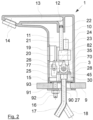
- the mixing fitting 1 selected as an embodiment has a mixing device in the form of a mixing valve 3, which can be adjusted via an adjusting device 7. It is provided with a control 20 and a solenoid valve 23.
- the mixer tap 1 is arranged on a washbasin 9.
- the tap 1 has a threaded pin 16 which projects through a tap hole 90 in the washbasin 9.
- a clamping disk 91 is positioned on the washbasin 9, which is supported by the Threaded pin 16 passes through it and is clamped to the wash basin 9 with a nut 92.
- a seal 93 is provided between the mixer tap 1 and the wash basin 9.
- the tap 1 is connected to a cold water connection pipe 17 and a hot water connection pipe 18, with which the mixer tap 1 is connected to the pipe system of the respective building.
- the mixer tap 1 consists of a tap housing 10 in which an interior 11 is formed.
- the mixer valve 3, the adjusting device 7, the control 20 and the solenoid valve 23 are arranged in the interior 11.
- a connection bore 12 is formed in the mixer tap 1, which is connected to a drain channel 13, which ends in the outlet of the mixer tap 1 provided with a jet regulator 14.
- a base 15 is installed in the tap housing 10, via which the mixer tap 1 is in contact with the wash basin 9.
- an infrared window 19 is arranged in the tap housing 10, behind which the control 20 is positioned.
- the solenoid valve 23 is connected to a valve coil 24, which serves to actuate the solenoid valve 23.
- a drive 25 for actuating the mixing valve 3 is provided in the housing 10.
- the drive 25 is preferably a motor, which can be a servo motor or a stepper motor. In the de-energized state, i.e. the rest state, the actuating movement of the drive 25 is freely movable.
- All the components provided in the housing 10 are attached to a holder 26.
- spacer sleeves 27 are provided for the construction of the mixing valve 3, which correspond to screws 28.
- the connection of the cold water connection pipe 17 and the hot water connection pipe 18 to the connection hole 12 takes place with the interposition of the mixing device via a connection pipe 21, which is sealed against the connection hole 12 with a seal 22.
- the manual temperature setting of the mixing valve 1 is carried out via a handle 29 which is arranged on the outside of the valve housing 10.
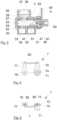
- the mixing device in the form of the mixing valve 3 is formed by a housing, as shown for example in Figure 6 is shown.
- a mixer shaft 49 is inserted into the housing.
- the housing of the mixing valve 3 has an inlet nozzle 30 which is provided with a connection hole 31 for cold water and a connection hole 33 for hot water.
- the connection hole 31 opens into an inlet 32; the connection hole 33 opens into an inlet 34.
- the inlets 32 and 34 connect the connection holes 31 and 33 with a receiving hole 40 for the mixer shaft 49.
- an outlet nozzle 35 is formed on the housing of the mixing valve 3, which is provided with a connection bore 36 for the outgoing mixed water.
- the bottom of the connection bore 36 is formed by a through-channel 37, which opens into a connection with an outlet 38 for the mixed water, which in turn is connected to the receiving bore 40 for the mixer shaft 49.
- the outlet nozzle 35 is also provided with bores 39 for locking pins (not shown).
- the receiving bore 40 for the mixer shaft 49 is provided at one end with an inlet bore 41 for the mixer shaft 49, which has bores 42 for locking pins 48.
- a threaded bore 43 for receiving a stop screw 62 is made in the wall of the inlet bore 41 radially to the receiving bore 40.
- the threaded bore 43 is surrounded on the outside by a shoulder 44.
- three fastening tabs 45 are formed on the circumference of the housing of the mixing valve 3, each of which is provided with a bore 46 and with which the mixing valve 3 can be fastened in the fitting housing 10.
- the mixer shaft 49 has a base 50 at one end, in which a groove 56 is formed for receiving the mixer shaft lever 70.
- a threaded hole 57 is made in the bottom of the groove 56.
- On the outside, in the A groove 58 is made in the base 50, which extends in some areas over the circumference of the base 50 and serves to limit the stop for the mixer shaft 49.
- two further annular grooves 60 are also provided to accommodate seals 47, with which the mixer shaft 49 is sealed against the receiving bore 40 of the mixing valve 3.
- the mixer shaft 49 is provided with a mixing chamber 54, which is provided with an inlet bore 51 for cold water, an inlet bore 52 for hot water and a mixed water outlet channel 53, offset from one another on its circumference.
- the mixing chamber 54 ends in a blind hole 55.
- the adjustment device 7 essentially consists of the mixer shaft lever 70 and a drive shaft lever 77, which are connected to one another via a bracket 82.
- the mixer shaft lever 70 comprises a base 71, which has a connection bore 74, which merges into a through-bore 75 of smaller diameter.
- the mixer shaft lever 70 is provided with a shoulder 72, which corresponds to the groove 56 of the mixer shaft 49.
- the shoulder 72 is provided with a flattened area 73.
- a screw 61 which can be screwed into the threaded bore 57 of the mixer shaft 49, is used to mount the mixer shaft lever 70 on the mixer shaft 49.
- the mixer shaft lever 70 is provided with a bore 76 for fastening the bracket 82.
- the drive shaft lever 77 has a base 78 through which a through hole 79 passes.
- a threaded hole 80 protrudes radially into the through hole 79 and serves to accommodate a locking screw.
- a hole 81 for fastening the bracket 82 is provided in the drive shaft lever 77.
- the bracket 82 has a U-shaped design. This creates two pins 83 that are aligned parallel to one another and each have an annular groove 84. When assembled, the annular grooves 84 accommodate locking washers 85 for reliable fastening of the bracket 82.
- the mixer tap according to the invention makes it possible to carry out an automatic hygiene flush. This is ensured by the fact that at the start of an automatic hygiene flush when the solenoid valve 23 is opened, the mixer valve 3 can be moved into an open position with the aid of the drive 25, which can differ from the random setting of the temperature by the last user. This is ensured by the fact that the drive 25 is connected to the adjustment device 7, which adjusts the mixer shaft to the predetermined position for a hygiene flush. Depending on the programming, this can be a mixed position of cold and warm water in order to ensure that both the cold water line and the warm water line are flushed with just one flush.
- a cold water setting is selected first and after a sufficient time the warm water position is adopted, or vice versa.
- the solenoid valve 23 is opened to allow water to enter the mixing valve according to the invention. After the preset flushing time has elapsed, the solenoid valve 23 is closed. It can be provided that the mixing valve moves to a preprogrammed position after the specified flushing time. Alternatively, it can also be provided that the mixing valve remains in the last flushing position. Of course, it is possible to specify different flushing times as part of the programming depending on the respective opening positions.
- the invention opens up the possibility of providing an automatic hygiene flush even on fittings that are equipped with a manual mixing device.
- the mixing fitting according to the invention offers the possibility of arranging the components used in an electronic wash basin fitting of a conventional size. Consequently, the mixing fitting according to the invention can be combined with conventional components known from the sanitary sector without having to make any changes to other components.
- the mixer fitting according to the invention is capable of independently carrying out so-called hygiene flushes.
- the control 20 has a time measuring device in which a time interval can be set after which a forced flush of the mixer fitting according to the invention should take place. If the mixer fitting is not used within the preset period of time, an automated hygiene flush takes place. This is done by a signal sent by the control 20, which is directed to the drive 25. The drive 25 comes into operation as a result of this signal, which leads to a movement of the drive shaft lever 77, which in turn results in a movement of the mixer shaft lever 70 via the bracket 82.
- the drive 25 is in operation until the mixer shaft 49 has reached an open position in which water enters the mixer fitting 1 from both the hot water connection pipe 18 and the cold water connection pipe 17.
- This is preferably the middle position, i.e. the position in which equal amounts of cold and warm water flow through the fitting.
- the open position first provides a cold water flush and then a warm water flush, or vice versa. This moves the mixer shaft 49 into a mixed water position.
- the solenoid valve 23 is then activated and the inlet of the mixer fitting 1 is released so that water can enter the fitting.
- the design according to the invention flushes both the cold water pipe and the hot water pipe, thereby preventing the water in the pipes from becoming contaminated.
- the control 20 sends out a signal again, which causes the solenoid valve 23 to close. No more water then enters or leaves the tap.
- the programming of the control 20 can provide that the mixer valve 3 or the thermostat is brought into a predetermined opening position of the cold and/or hot water inlet by means of the drive 25 after the solenoid valve 23 has closed. Irrespective of this, the next flushing process takes place either when a user activates the mixer tap or when the preset period of non-use is exceeded again and thus a compulsory hygiene flush is carried out again, as described above.
- the invention creates a mixer tap that enables forced flushing of the mixer tap to avoid stagnant water despite manual temperature adjustment and at the same time realizes this in a housing that has the dimensions of conventional mixer taps. Such a solution is not known from the prior art.
Landscapes
- Health & Medical Sciences (AREA)
- Life Sciences & Earth Sciences (AREA)
- Engineering & Computer Science (AREA)
- Hydrology & Water Resources (AREA)
- Public Health (AREA)
- Water Supply & Treatment (AREA)
- Domestic Plumbing Installations (AREA)
- Multiple-Way Valves (AREA)
Claims (7)
- Robinet mitigeur pour un rinçage hygiénique fiable et automatique des conduites d'eau froide et d'eau chaude, comprenant un corps (10) de robinet ainsi que la commande électronique (20) et le circuit sensoriel servant à détecter la présence d'un utilisateur, avec des raccords pour l'eau froide et l'eau chaude et avec une électrovanne (23) à actionnement électrique ainsi qu'un dispositif mitigeur ajustable manuellement, officiant de vanne mélangeuse (3) avec arbre (49) mitigeur ou comme thermostat, sachant qu'est prévu un entraînement (25) fonctionnant à l'électricité et qui est relié à un dispositif d'ajustement (7) lui-même relié à la vanne mélangeuse (3) ou au thermostat, sachant que la commande (20), le circuit sensoriel servant à détecter la présence d'un utilisateur, l'électrovanne (23), la vanne mélangeuse (3), l'entraînement (25) et le dispositif d'ajustement (7) sont disposés dans le corps du robinet (10), caractérisé en ce que le libre mouvement d'ajustement de l'entraînement (25) et ainsi celui du dispositif mitigeur qui lui est relié sont possibles - à l'état hors tension -, de sorte que le dispositif mitigeur du robinet mitigeur est, en service normal, utilisable manuellement sans restriction par l'utilisateur respectif, sachant qu'au début d'un rinçage hygiénique automatique, lors de l'ouverture de l'électrovanne (23), la vanne mélangeuse (3) est déplaçable à l'aide de l'entraînement (25) vers une position ouverte, du fait que l'entraînement (25) se trouve relié au dispositif d'ajustement (7), dispositif qui déplace l'arbre mitigeur (49) et/ou le thermostat jusque sur la position spécifiée en vue d'un rinçage hygiénique.
- Robinet mitigeur selon la revendication 1, caractérisé en ce que l'entraînement (25) est un moteur.
- Robinet mitigeur selon l'une des revendications 1 ou 2, caractérisé en ce que l'entraînement (25) est un servomoteur.
- Robinet mitigeur selon l'une des revendications 1 ou 2, caractérisé en ce que l'entraînement (25) est un moteur pas à pas.
- Robinet mitigeur selon l'une des revendications 1 à 4, caractérisé en ce que l'entraînement (25) et la vanne mélangeuse (3) ou le thermostat sont reliés entre eux par un étrier (82).
- Robinet mitigeur selon l'une des revendications 1 à 4, caractérisé en ce que l'entraînement (25) et la vanne mélangeuse (3) ou le thermostat sont reliés entre eux par des pignons cylindriques ou coniques.
- Robinet mitigeur selon l'une des revendications 1 à 4, caractérisé en ce que l'entraînement (25) et la vanne mélangeuse (3) ou le thermostat sont reliés entre eux par un entraînement à courroie.
Applications Claiming Priority (1)
| Application Number | Priority Date | Filing Date | Title |
|---|---|---|---|
| DE102018104571.9A DE102018104571A1 (de) | 2018-02-28 | 2018-02-28 | Mischarmatur |
Publications (2)
| Publication Number | Publication Date |
|---|---|
| EP3533941A1 EP3533941A1 (fr) | 2019-09-04 |
| EP3533941B1 true EP3533941B1 (fr) | 2025-01-08 |
Family
ID=65628604
Family Applications (1)
| Application Number | Title | Priority Date | Filing Date |
|---|---|---|---|
| EP19159569.3A Active EP3533941B1 (fr) | 2018-02-28 | 2019-02-27 | Robinet mélangeur |
Country Status (2)
| Country | Link |
|---|---|
| EP (1) | EP3533941B1 (fr) |
| DE (1) | DE102018104571A1 (fr) |
Families Citing this family (3)
| Publication number | Priority date | Publication date | Assignee | Title |
|---|---|---|---|---|
| CN113958747B (zh) * | 2020-07-21 | 2025-07-18 | 路达(厦门)工业有限公司 | 感应出水龙头 |
| DE202021004307U1 (de) | 2021-11-11 | 2023-07-25 | Schell GmbH & Co. KG. | Mischarmatur |
| DE102021129400A1 (de) | 2021-11-11 | 2023-05-11 | Schell Gmbh & Co. Kg | Mischarmatur |
Family Cites Families (9)
| Publication number | Priority date | Publication date | Assignee | Title |
|---|---|---|---|---|
| DE2821692A1 (de) | 1978-05-18 | 1979-11-22 | Hansa Metallwerke Ag | Sanitaere mischwasser-armatur |
| DE3518644A1 (de) | 1985-05-23 | 1986-11-27 | Knebel & Röttger GmbH & Co, 5860 Iserlohn | Sanitaer-mischarmatur |
| DE3718039C2 (de) | 1987-05-28 | 1994-04-21 | Ideal Standard | Elektronisch temperaturgeregelte Mischarmatur |
| DE10148675C1 (de) | 2001-10-02 | 2003-12-04 | Mepa Pauli Und Menden Gmbh Wie | Wasserarmatur mit Anwesenheitsdetektor |
| GB0500970D0 (en) * | 2005-01-18 | 2005-02-23 | Kohler Mira Ltd | Improvements in or relating to ablutionary Installations |
| AT10563U1 (de) * | 2007-12-20 | 2009-06-15 | Herbert Wimberger | Verfahren zur thermischen desinfektion und armaturen zum durchfuhren dieser verfahren |
| DE102011008804B4 (de) * | 2011-01-18 | 2012-09-20 | Schell Gmbh & Co. Kg | Sanitärarmatur |
| DE102014104393A1 (de) * | 2013-04-05 | 2014-10-09 | Herbert Wimberger | Sanitärarmatur mit Präventivspülung |
| DE202016004151U1 (de) * | 2016-07-05 | 2017-04-07 | Klaus Michael Held | Elektronische Steuerung für Sanitärarmaturen mit bedarfsangepassten Durchflüssen und Steuerungselektronik über elektronischen Drehschalter oder zeitabhängiger elektronischer Tastersteuerung auch in Verbindung mit berührungsfreier Sensorelektronik |
-
2018
- 2018-02-28 DE DE102018104571.9A patent/DE102018104571A1/de active Pending
-
2019
- 2019-02-27 EP EP19159569.3A patent/EP3533941B1/fr active Active
Also Published As
| Publication number | Publication date |
|---|---|
| DE102018104571A1 (de) | 2019-08-29 |
| EP3533941A1 (fr) | 2019-09-04 |
Similar Documents
| Publication | Publication Date | Title |
|---|---|---|
| EP2946041B1 (fr) | Robinet sanitaire | |
| EP3115518B1 (fr) | Robinetterie comprenant deux soupapes | |
| EP3420430B1 (fr) | Vanne de mélange thermostatique | |
| EP3533941B1 (fr) | Robinet mélangeur | |
| DE202009000525U1 (de) | Elektronisch regelbare Mischvorrichtung für Leitungswasser | |
| EP2564283A1 (fr) | Robinet mélangeur sanitaire, en particulier pour une douche | |
| DE60008853T2 (de) | Vorrichtung zur automatischen Wasserabgabe | |
| DE102011008804B4 (de) | Sanitärarmatur | |
| AT399212B (de) | Adapterarmatur zum wahlweisen anschluss eines heizkörpers | |
| DE19525358C2 (de) | Einhebelmischbatterie zur Unterputzmontage | |
| EP2406529A2 (fr) | Mélangeur à levier unique pour un robinet d'eau | |
| EP2169124B1 (fr) | Armature pouvant être commandée électroniquement destinée au mélange d'eau froide et d'eau chaude, notamment pour une table de lavage | |
| DE102010023574A1 (de) | Eckventil | |
| DE102021129400A1 (de) | Mischarmatur | |
| DE2252395C3 (de) | Umschalter für ein System Wanne-Brause | |
| DE2007572A1 (de) | Waschtisch mit einem Wasserausfluß | |
| EP3112540A1 (fr) | Partie superieure de soupape | |
| DE202021004307U1 (de) | Mischarmatur | |
| EP2604896B1 (fr) | Dispositif de mélange pour eau du robinet | |
| EP4286614A1 (fr) | Robinetterie sanitaire pourvue de robinets d'arrêt | |
| EP0855635B1 (fr) | Robinetterie sanitaire | |
| EP4509664A1 (fr) | Robinet de sortie protégé contre le gel | |
| EP2829943A2 (fr) | Robinetterie thermostatique sanitaire | |
| EP4524333A1 (fr) | Unité de soupape destinée à être utilisée dans une robinetterie sanitaire | |
| DE102021127586A1 (de) | Vorrichtung zur Durchführung von Hygienespülungen in Sanitärarmaturen |
Legal Events
| Date | Code | Title | Description |
|---|---|---|---|
| PUAI | Public reference made under article 153(3) epc to a published international application that has entered the european phase |
Free format text: ORIGINAL CODE: 0009012 |
|
| STAA | Information on the status of an ep patent application or granted ep patent |
Free format text: STATUS: THE APPLICATION HAS BEEN PUBLISHED |
|
| AK | Designated contracting states |
Kind code of ref document: A1 Designated state(s): AL AT BE BG CH CY CZ DE DK EE ES FI FR GB GR HR HU IE IS IT LI LT LU LV MC MK MT NL NO PL PT RO RS SE SI SK SM TR |
|
| AX | Request for extension of the european patent |
Extension state: BA ME |
|
| STAA | Information on the status of an ep patent application or granted ep patent |
Free format text: STATUS: REQUEST FOR EXAMINATION WAS MADE |
|
| 17P | Request for examination filed |
Effective date: 20200302 |
|
| RBV | Designated contracting states (corrected) |
Designated state(s): AL AT BE BG CH CY CZ DE DK EE ES FI FR GB GR HR HU IE IS IT LI LT LU LV MC MK MT NL NO PL PT RO RS SE SI SK SM TR |
|
| STAA | Information on the status of an ep patent application or granted ep patent |
Free format text: STATUS: EXAMINATION IS IN PROGRESS |
|
| 17Q | First examination report despatched |
Effective date: 20201201 |
|
| GRAP | Despatch of communication of intention to grant a patent |
Free format text: ORIGINAL CODE: EPIDOSNIGR1 |
|
| STAA | Information on the status of an ep patent application or granted ep patent |
Free format text: STATUS: GRANT OF PATENT IS INTENDED |
|
| INTG | Intention to grant announced |
Effective date: 20240920 |
|
| GRAS | Grant fee paid |
Free format text: ORIGINAL CODE: EPIDOSNIGR3 |
|
| GRAA | (expected) grant |
Free format text: ORIGINAL CODE: 0009210 |
|
| STAA | Information on the status of an ep patent application or granted ep patent |
Free format text: STATUS: THE PATENT HAS BEEN GRANTED |
|
| AK | Designated contracting states |
Kind code of ref document: B1 Designated state(s): AL AT BE BG CH CY CZ DE DK EE ES FI FR GB GR HR HU IE IS IT LI LT LU LV MC MK MT NL NO PL PT RO RS SE SI SK SM TR |
|
| REG | Reference to a national code |
Ref country code: GB Ref legal event code: FG4D Free format text: NOT ENGLISH |
|
| REG | Reference to a national code |
Ref country code: CH Ref legal event code: EP |
|
| REG | Reference to a national code |
Ref country code: DE Ref legal event code: R096 Ref document number: 502019012760 Country of ref document: DE |
|
| REG | Reference to a national code |
Ref country code: IE Ref legal event code: FG4D Free format text: LANGUAGE OF EP DOCUMENT: GERMAN |
|
| P01 | Opt-out of the competence of the unified patent court (upc) registered |
Free format text: CASE NUMBER: APP_4884/2025 Effective date: 20250129 |
|
| REG | Reference to a national code |
Ref country code: NL Ref legal event code: FP |
|
| PGFP | Annual fee paid to national office [announced via postgrant information from national office to epo] |
Ref country code: DE Payment date: 20250218 Year of fee payment: 7 |
|
| PGFP | Annual fee paid to national office [announced via postgrant information from national office to epo] |
Ref country code: NL Payment date: 20250228 Year of fee payment: 7 |
|
| PGFP | Annual fee paid to national office [announced via postgrant information from national office to epo] |
Ref country code: AT Payment date: 20250328 Year of fee payment: 7 Ref country code: BE Payment date: 20250228 Year of fee payment: 7 |
|
| REG | Reference to a national code |
Ref country code: LT Ref legal event code: MG9D |
|
| PG25 | Lapsed in a contracting state [announced via postgrant information from national office to epo] |
Ref country code: RS Free format text: LAPSE BECAUSE OF FAILURE TO SUBMIT A TRANSLATION OF THE DESCRIPTION OR TO PAY THE FEE WITHIN THE PRESCRIBED TIME-LIMIT Effective date: 20250408 |
|
| PG25 | Lapsed in a contracting state [announced via postgrant information from national office to epo] |
Ref country code: FI Free format text: LAPSE BECAUSE OF FAILURE TO SUBMIT A TRANSLATION OF THE DESCRIPTION OR TO PAY THE FEE WITHIN THE PRESCRIBED TIME-LIMIT Effective date: 20250108 |
|
| PG25 | Lapsed in a contracting state [announced via postgrant information from national office to epo] |
Ref country code: PL Free format text: LAPSE BECAUSE OF FAILURE TO SUBMIT A TRANSLATION OF THE DESCRIPTION OR TO PAY THE FEE WITHIN THE PRESCRIBED TIME-LIMIT Effective date: 20250108 |
|
| PG25 | Lapsed in a contracting state [announced via postgrant information from national office to epo] |
Ref country code: ES Free format text: LAPSE BECAUSE OF FAILURE TO SUBMIT A TRANSLATION OF THE DESCRIPTION OR TO PAY THE FEE WITHIN THE PRESCRIBED TIME-LIMIT Effective date: 20250108 |
|
| PG25 | Lapsed in a contracting state [announced via postgrant information from national office to epo] |
Ref country code: IS Free format text: LAPSE BECAUSE OF FAILURE TO SUBMIT A TRANSLATION OF THE DESCRIPTION OR TO PAY THE FEE WITHIN THE PRESCRIBED TIME-LIMIT Effective date: 20250508 Ref country code: NO Free format text: LAPSE BECAUSE OF FAILURE TO SUBMIT A TRANSLATION OF THE DESCRIPTION OR TO PAY THE FEE WITHIN THE PRESCRIBED TIME-LIMIT Effective date: 20250408 |
|
| PG25 | Lapsed in a contracting state [announced via postgrant information from national office to epo] |
Ref country code: HR Free format text: LAPSE BECAUSE OF FAILURE TO SUBMIT A TRANSLATION OF THE DESCRIPTION OR TO PAY THE FEE WITHIN THE PRESCRIBED TIME-LIMIT Effective date: 20250108 |
|
| PG25 | Lapsed in a contracting state [announced via postgrant information from national office to epo] |
Ref country code: LV Free format text: LAPSE BECAUSE OF FAILURE TO SUBMIT A TRANSLATION OF THE DESCRIPTION OR TO PAY THE FEE WITHIN THE PRESCRIBED TIME-LIMIT Effective date: 20250108 Ref country code: PT Free format text: LAPSE BECAUSE OF FAILURE TO SUBMIT A TRANSLATION OF THE DESCRIPTION OR TO PAY THE FEE WITHIN THE PRESCRIBED TIME-LIMIT Effective date: 20250508 |
|
| PG25 | Lapsed in a contracting state [announced via postgrant information from national office to epo] |
Ref country code: GR Free format text: LAPSE BECAUSE OF FAILURE TO SUBMIT A TRANSLATION OF THE DESCRIPTION OR TO PAY THE FEE WITHIN THE PRESCRIBED TIME-LIMIT Effective date: 20250409 Ref country code: BG Free format text: LAPSE BECAUSE OF FAILURE TO SUBMIT A TRANSLATION OF THE DESCRIPTION OR TO PAY THE FEE WITHIN THE PRESCRIBED TIME-LIMIT Effective date: 20250108 |
|
| PG25 | Lapsed in a contracting state [announced via postgrant information from national office to epo] |
Ref country code: SE Free format text: LAPSE BECAUSE OF FAILURE TO SUBMIT A TRANSLATION OF THE DESCRIPTION OR TO PAY THE FEE WITHIN THE PRESCRIBED TIME-LIMIT Effective date: 20250108 |
|
| REG | Reference to a national code |
Ref country code: CH Ref legal event code: PL |
|
| PG25 | Lapsed in a contracting state [announced via postgrant information from national office to epo] |
Ref country code: SM Free format text: LAPSE BECAUSE OF FAILURE TO SUBMIT A TRANSLATION OF THE DESCRIPTION OR TO PAY THE FEE WITHIN THE PRESCRIBED TIME-LIMIT Effective date: 20250108 |
|
| REG | Reference to a national code |
Ref country code: DE Ref legal event code: R097 Ref document number: 502019012760 Country of ref document: DE |
|
| PG25 | Lapsed in a contracting state [announced via postgrant information from national office to epo] |
Ref country code: DK Free format text: LAPSE BECAUSE OF FAILURE TO SUBMIT A TRANSLATION OF THE DESCRIPTION OR TO PAY THE FEE WITHIN THE PRESCRIBED TIME-LIMIT Effective date: 20250108 |
|
| PG25 | Lapsed in a contracting state [announced via postgrant information from national office to epo] |
Ref country code: MC Free format text: LAPSE BECAUSE OF FAILURE TO SUBMIT A TRANSLATION OF THE DESCRIPTION OR TO PAY THE FEE WITHIN THE PRESCRIBED TIME-LIMIT Effective date: 20250108 |
|
| PG25 | Lapsed in a contracting state [announced via postgrant information from national office to epo] |
Ref country code: LU Free format text: LAPSE BECAUSE OF NON-PAYMENT OF DUE FEES Effective date: 20250227 |
|
| PG25 | Lapsed in a contracting state [announced via postgrant information from national office to epo] |
Ref country code: CH Free format text: LAPSE BECAUSE OF NON-PAYMENT OF DUE FEES Effective date: 20250228 |
|
| PG25 | Lapsed in a contracting state [announced via postgrant information from national office to epo] |
Ref country code: CZ Free format text: LAPSE BECAUSE OF FAILURE TO SUBMIT A TRANSLATION OF THE DESCRIPTION OR TO PAY THE FEE WITHIN THE PRESCRIBED TIME-LIMIT Effective date: 20250108 Ref country code: EE Free format text: LAPSE BECAUSE OF FAILURE TO SUBMIT A TRANSLATION OF THE DESCRIPTION OR TO PAY THE FEE WITHIN THE PRESCRIBED TIME-LIMIT Effective date: 20250108 |
|
| PG25 | Lapsed in a contracting state [announced via postgrant information from national office to epo] |
Ref country code: RO Free format text: LAPSE BECAUSE OF FAILURE TO SUBMIT A TRANSLATION OF THE DESCRIPTION OR TO PAY THE FEE WITHIN THE PRESCRIBED TIME-LIMIT Effective date: 20250108 |
|
| PG25 | Lapsed in a contracting state [announced via postgrant information from national office to epo] |
Ref country code: SK Free format text: LAPSE BECAUSE OF FAILURE TO SUBMIT A TRANSLATION OF THE DESCRIPTION OR TO PAY THE FEE WITHIN THE PRESCRIBED TIME-LIMIT Effective date: 20250108 |
|
| PLBE | No opposition filed within time limit |
Free format text: ORIGINAL CODE: 0009261 |
|
| STAA | Information on the status of an ep patent application or granted ep patent |
Free format text: STATUS: NO OPPOSITION FILED WITHIN TIME LIMIT |
|
| 26N | No opposition filed |
Effective date: 20251009 |
|
| GBPC | Gb: european patent ceased through non-payment of renewal fee |
Effective date: 20250408 |
|
| PG25 | Lapsed in a contracting state [announced via postgrant information from national office to epo] |
Ref country code: GB Free format text: LAPSE BECAUSE OF NON-PAYMENT OF DUE FEES Effective date: 20250408 |
|
| PG25 | Lapsed in a contracting state [announced via postgrant information from national office to epo] |
Ref country code: FR Free format text: LAPSE BECAUSE OF NON-PAYMENT OF DUE FEES Effective date: 20250308 |
|
| PG25 | Lapsed in a contracting state [announced via postgrant information from national office to epo] |
Ref country code: IE Free format text: LAPSE BECAUSE OF NON-PAYMENT OF DUE FEES Effective date: 20250227 |
|
| PG25 | Lapsed in a contracting state [announced via postgrant information from national office to epo] |
Ref country code: IT Free format text: LAPSE BECAUSE OF FAILURE TO SUBMIT A TRANSLATION OF THE DESCRIPTION OR TO PAY THE FEE WITHIN THE PRESCRIBED TIME-LIMIT Effective date: 20250108 |