EP3533941A1 - Robinet mélangeur - Google Patents
Robinet mélangeur Download PDFInfo
- Publication number
- EP3533941A1 EP3533941A1 EP19159569.3A EP19159569A EP3533941A1 EP 3533941 A1 EP3533941 A1 EP 3533941A1 EP 19159569 A EP19159569 A EP 19159569A EP 3533941 A1 EP3533941 A1 EP 3533941A1
- Authority
- EP
- European Patent Office
- Prior art keywords
- drive
- mixing valve
- mixing
- thermostat
- valve
- Prior art date
- Legal status (The legal status is an assumption and is not a legal conclusion. Google has not performed a legal analysis and makes no representation as to the accuracy of the status listed.)
- Pending
Links
Images


Classifications
-
- E—FIXED CONSTRUCTIONS
- E03—WATER SUPPLY; SEWERAGE
- E03C—DOMESTIC PLUMBING INSTALLATIONS FOR FRESH WATER OR WASTE WATER; SINKS
- E03C1/00—Domestic plumbing installations for fresh water or waste water; Sinks
- E03C1/02—Plumbing installations for fresh water
- E03C1/05—Arrangements of devices on wash-basins, baths, sinks, or the like for remote control of taps
- E03C1/055—Electrical control devices, e.g. with push buttons, control panels or the like
- E03C1/057—Electrical control devices, e.g. with push buttons, control panels or the like touchless, i.e. using sensors
Definitions
- the invention relates to a mixing valve with electronic control and sensor for user recognition, with connections for cold and hot water and an electrically operated solenoid valve and a manually adjustable mixing device as a mixing valve with a mixer shaft or as a thermostat.
- the invention also relates to a method for flushing the hot and / or cold water line by means of a mixing valve.
- the present invention seeks to provide a mixing valve with electronic control and manual mixing device, which ensures a reliable flushing of the cold and hot water pipe and their components can be arranged in an electronic sink fitting conventional size.
- this object is achieved in that a drive is provided, which is connected to an adjusting device which is connected to the mixing valve or the thermostat.
- a mixing valve with electronic control and manual mixing device is created, which ensures a reliable flushing of the cold and hot water pipe and their components can also be arranged in an electronic washstand fitting conventional size. This is ensured by the drive, which transmits via the adjusting movement to the mixing valve or the thermostat.
- the possibility is created, in the case of a hygiene flushing the mixing valve or the thermostat from a random position, which was selected by the last user to move to a preprogrammed position to ensure a reliable flushing of the cold and hot water pipe.
- the actuating movement of the drive in the de-energized state is freely movable. This design ensures that the mixing device of the mixing valve during normal operation of the respective user is manually operated without restriction. Only in the case of a hygiene flush subject to the mixing device of the forced movement under the influence of the drive and the adjusting device.
- the object is also achieved by a method for flushing the hot and / or cold water line by means of a mixing valve with connections for cold and hot water and an electrically operated solenoid valve and an electronic control and sensor for user recognition and a manually adjustable mixing device as a mixing valve or as a thermostat , which is brought at the beginning of an automatic hygiene flushing with opening of the solenoid valve, the mixing valve or the thermostat by means of the drive in a predetermined opening position of the cold and / or hot water supply.
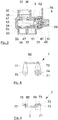
- the mixing fitting 1 chosen as an exemplary embodiment has a mixing device in the form of a mixing valve 3, which is adjustable via an adjusting device 7. It is provided with a controller 20 and a solenoid valve 23.
- the mixing fitting 1 is arranged on a washstand 9.
- the valve 1 has a threaded pin 16 which projects through a tap hole 90 in the wash basin 9.
- a clamping disk 91 is positioned on the washstand 9, which is penetrated by the threaded pin 16 and which is braced with a nut 92 on the wash basin 9.
- a seal 93 is provided between the mixing valve 1 and the washstand 9, a seal 93 is provided.
- the fitting 1 is connected to a cold water connection pipe 17 and a hot water connection pipe 18, with which the mixing fitting 1 is connected to the pipe system of the respective building.
- the mixing valve 1 consists of a fitting housing 10, in which an interior space 11 is formed. In the interior 11, the mixing valve 3, the adjusting device 7, the controller 20 and the solenoid valve 23 are arranged. On the side facing away from the wash basin 9, a connection bore 12 is formed in the mixing fitting 1, which communicates with a discharge channel 13, which terminates in the outlet of the mixing fitting 1 provided with a jet regulator 14. At the end facing the wash basin 9, a base 15 is installed in the fitting housing 10, via which the mixing fitting 1 is in contact with the wash basin 9. On the side into which the spout extends, an infrared window 19 is arranged in the fitting housing 10, behind which the controller 20 is positioned.
- the solenoid valve 23 is in communication with a valve spool 24 which serves to actuate the solenoid valve 23.
- a drive 25 for actuating the mixing valve 3 in the housing 10 is provided.
- the drive 25 is preferably a motor, which may be a servomotor or a stepper motor. In the de-energized state, ie the idle state, the actuating movement of the drive 25 is freely movable.
- the entire components provided in the housing 10 are fastened to a holder 26.
- spacer sleeves 27 are provided for the construction of the mixing valve 3 which correspond with screws 28.
- the connection of the cold water connection pipe 17 and the hot water connection pipe 18 with the connection bore 12 takes place with the interposition of the mixing device via a connection pipe 21, which is sealed with a seal 22 against the connection bore 12.
- the manual temperature setting of the mixing fitting 1 via a handle 29, which is arranged on the outside of the fitting housing 10.
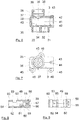
- the mixing device in the form of the mixing valve 3 is formed by a housing, as exemplified in FIG. 6 is shown.
- a mixer shaft 49 is inserted in the assembled state.
- the housing of the mixing valve 3 has an inlet connection 30, which is provided with a connection bore 31 for cold water and a connection bore 33 for hot water.
- the connection bore 31 opens into an inlet 32; the connection bore 33 opens into an inlet 34.
- the inlets 32 and 34 connect the connection bores 31 and 33 with a receiving bore 40 for the mixer shaft 49.
- an outlet nozzle 35 is formed on the housing of the mixing valve 3, which is provided with a connection bore 36 for the exiting mixed water.
- the bottom of the connection bore 36 is formed by a through-passage 37, which opens into connection with an outlet 38 for the mixed water, which in turn communicates with the receiving bore 40 for the mixer shaft 49.
- the outlet nozzle 35 is also provided with holes 39 for - not shown - locking pins.
- the receiving bore 40 for the mixer shaft 49 is provided at its one end with an inlet bore 41 for the mixer shaft 49, which has holes 42 for locking pins 48.
- a threaded bore 43 for receiving a stop screw 62 is introduced into the wall of the inlet bore 41. Outside, the threaded bore 43 is surrounded by a shoulder 44.
- three fastening tabs 45 are formed, which are each provided with a bore 46 and with which the mixing valve 3 in the fitting housing 10 can be fastened.
- the mixer shaft 49 has at its one end a base 50, in which a groove 56 for receiving the mixer shaft lever 70 is formed. In the bottom of the groove 56, a threaded bore 57 is introduced. Externally, a groove 58 is introduced into the base 50, which extends in regions over the circumference of the base 50 and which serves to limit the stop for the mixer shaft 49. Adjacent to the groove 58 is located in the mixer shaft 49, an annular groove 59, which forms an axial securing for the mixer shaft. Adjacent to this annular groove 59, a further annular groove 60 is formed which serves to receive a seal 47. In addition, in the exemplary embodiment, two further annular grooves 60 are also provided for receiving seals 47, with which the mixer shaft 49 is sealed against the receiving bore 40 of the mixing valve 3.
- the mixer shaft 49 is provided with a mixing chamber 54 which is offset on its circumference to each other with an inlet bore 51 for cold water, an inlet bore 52 for hot water and a mixed water outlet channel 53 is provided.
- the mixing chamber 54 ends in a blind hole 55.
- the adjusting device 7 consists essentially of the mixer shaft lever 70 and a drive shaft lever 77, which are connected to each other via a bracket 82.
- the mixer shaft lever 70 includes a base 71 having a connection bore 74 that merges into a smaller diameter through bore 75.
- On its in the assembled state of the mixer shaft 49 side facing the mixer shaft lever 70 is provided with a shoulder 72 which corresponds to the groove 56 of the mixer shaft 49.
- the paragraph 72 is provided with a flattening 73.
- a screw 61 which is screwed into the threaded bore 57 of the mixer shaft 49.
- At its end facing away from the base 71 of the mixer shaft lever 70 is provided with a bore 76 for fixing the bracket 82.
- the drive shaft lever 77 has a base 78 which is penetrated by a through hole 79. Radially into the through hole 79 projects a threaded hole 80, which serves to receive a locking screw. At the end facing away from the base 78, a bore 81 for fixing the bracket 82 is provided in the drive shaft lever 77.
- the bracket 82 has a U-shaped configuration. As a result, two parallel aligned pins 83 are caused, which are each provided with an annular groove 84.
- the annular grooves 84 take in the assembled state lock washers 85 for reliable attachment of the bracket 82.
- the mixing valve according to the invention in contrast to the known from the prior art mixing valves with manual adjustment of the temperature mixing device, the possibility to make an automatic hygiene flush. This is ensured by the fact that at the beginning of an automatic hygiene flush when opening the solenoid valve 23, the mixing valve 3 can be moved by means of the drive 25 in an open position, which may differ from the random setting of the temperature by the last user. This is ensured by the fact that the drive 25 is in communication with the adjusting device 7, which adjusts the mixer shaft in the predetermined position for a hygiene flush. Depending on the programming, this may be a mix of cold and hot water to ensure that both the cold water line and the hot water level are flushed out with a single flush.
- the solenoid valve 23 is opened to allow the entry of water into the mixing valve according to the invention. After expiration of the preset purge time, the solenoid valve 23 is closed. It can be provided that the mixing valve moves after the predetermined flushing time in a preprogrammed position. Alternatively, it can also be provided that the mixing valve remains in the last rinsing position. Of course, there is the Possibility to specify different flushing times depending on the respective opening positions during programming.
- a bracket by front or bevel gears.
- the use of a belt drive is basically possible here.
- a thermostat can also be used.
- the invention opens up the possibility of providing an automatic hygiene flush also on fittings which are provided with a manual mixing device.
- the mixing fitting according to the invention offers the possibility of arranging the components used also in an electronic washstand fitting of conventional size. Consequently, the mixing fitting according to the invention can be combined with conventional assemblies known from the sanitary sector, without having to make a change to other assemblies here.
- the mixing fitting according to the invention is capable of independently carrying out so-called hygienic rinsing.
- the controller 20 has a time measuring device, in which a time interval is adjustable, after which a forced flushing of the mixing valve according to the invention is to take place. If the mixing valve is not used within the pre-set period of time, an automated hygiene rinse takes place. This is done by a signal emitted by the controller 20, which is directed to the drive 25. The drive 25 comes into operation as a result of this signal, which leads to a movement of the drive shaft lever 77, which in turn via the bracket 82 has a movement of the mixer shaft lever 70 result.
- the drive 25 is in operation until the mixer shaft 49 has reached an open position in which 17 enters the mixing valve 1 from both the hot water connection pipe 18 and from the cold water connection pipe 17.
- this is the middle position, ie the position in which equal amounts of cold and warm water flow through the valve.
- the opening position initially provides a cold water flushing and then provides a hot water flushing, or vice versa.
- the mixer shaft 49 is moved to a mixed water position.
- the solenoid valve 23 is controlled and released the inlet of the mixing valve 1, so that water can enter the valve.
- both the cold water line and the hot water line are flushed by the design according to the invention, whereby a contamination of the upcoming in the lines of water is avoided.
- the controller 20 Upon expiration of a pre-programmed purge time in the controller 20, in which the water flows through the mixing valve, the controller 20 again sends out a signal that causes the solenoid valve 23 to close. There is then no more water in the valve on and off.
- the programming of the controller 20 may provide that the mixing valve 3 or the thermostat is brought by closing the solenoid valve 23 by means of the drive 25 in a predetermined opening position of the cold and / or hot water supply. Regardless of this, the next flushing operation will either occur when a user activates the mixing fixture or once again oversteps the preset period of non-use, again performing a forced sanitary flush as described above.
- a mixing valve is provided which allows a forced flushing of the mixing valve to avoid stagnant water despite manual temperature setting and this simultaneously realized in a housing having the dimensions of conventional mixing valves.
- Such a solution is not known from the prior art.
Landscapes
- Health & Medical Sciences (AREA)
- Life Sciences & Earth Sciences (AREA)
- Engineering & Computer Science (AREA)
- Hydrology & Water Resources (AREA)
- Public Health (AREA)
- Water Supply & Treatment (AREA)
- Domestic Plumbing Installations (AREA)
- Multiple-Way Valves (AREA)
Applications Claiming Priority (1)
| Application Number | Priority Date | Filing Date | Title |
|---|---|---|---|
| DE102018104571.9A DE102018104571A1 (de) | 2018-02-28 | 2018-02-28 | Mischarmatur |
Publications (1)
| Publication Number | Publication Date |
|---|---|
| EP3533941A1 true EP3533941A1 (fr) | 2019-09-04 |
Family
ID=65628604
Family Applications (1)
| Application Number | Title | Priority Date | Filing Date |
|---|---|---|---|
| EP19159569.3A Pending EP3533941A1 (fr) | 2018-02-28 | 2019-02-27 | Robinet mélangeur |
Country Status (2)
| Country | Link |
|---|---|
| EP (1) | EP3533941A1 (fr) |
| DE (1) | DE102018104571A1 (fr) |
Families Citing this family (2)
| Publication number | Priority date | Publication date | Assignee | Title |
|---|---|---|---|---|
| DE102021129400A1 (de) | 2021-11-11 | 2023-05-11 | Schell Gmbh & Co. Kg | Mischarmatur |
| DE202021004307U1 (de) | 2021-11-11 | 2023-07-25 | Schell GmbH & Co. KG. | Mischarmatur |
Citations (7)
| Publication number | Priority date | Publication date | Assignee | Title |
|---|---|---|---|---|
| DE2821692A1 (de) | 1978-05-18 | 1979-11-22 | Hansa Metallwerke Ag | Sanitaere mischwasser-armatur |
| DE3518644C2 (fr) | 1985-05-23 | 1989-01-26 | Knebel & Roettger Gmbh & Co, 5860 Iserlohn, De | |
| DE3718039C2 (de) | 1987-05-28 | 1994-04-21 | Ideal Standard | Elektronisch temperaturgeregelte Mischarmatur |
| DE10148675C1 (de) | 2001-10-02 | 2003-12-04 | Mepa Pauli Und Menden Gmbh Wie | Wasserarmatur mit Anwesenheitsdetektor |
| DE102011008804B4 (de) | 2011-01-18 | 2012-09-20 | Schell Gmbh & Co. Kg | Sanitärarmatur |
| DE102014104393A1 (de) * | 2013-04-05 | 2014-10-09 | Herbert Wimberger | Sanitärarmatur mit Präventivspülung |
| DE202016004151U1 (de) * | 2016-07-05 | 2017-04-07 | Klaus Michael Held | Elektronische Steuerung für Sanitärarmaturen mit bedarfsangepassten Durchflüssen und Steuerungselektronik über elektronischen Drehschalter oder zeitabhängiger elektronischer Tastersteuerung auch in Verbindung mit berührungsfreier Sensorelektronik |
Family Cites Families (2)
| Publication number | Priority date | Publication date | Assignee | Title |
|---|---|---|---|---|
| GB0500970D0 (en) * | 2005-01-18 | 2005-02-23 | Kohler Mira Ltd | Improvements in or relating to ablutionary Installations |
| AT10563U1 (de) * | 2007-12-20 | 2009-06-15 | Herbert Wimberger | Verfahren zur thermischen desinfektion und armaturen zum durchfuhren dieser verfahren |
-
2018
- 2018-02-28 DE DE102018104571.9A patent/DE102018104571A1/de active Pending
-
2019
- 2019-02-27 EP EP19159569.3A patent/EP3533941A1/fr active Pending
Patent Citations (7)
| Publication number | Priority date | Publication date | Assignee | Title |
|---|---|---|---|---|
| DE2821692A1 (de) | 1978-05-18 | 1979-11-22 | Hansa Metallwerke Ag | Sanitaere mischwasser-armatur |
| DE3518644C2 (fr) | 1985-05-23 | 1989-01-26 | Knebel & Roettger Gmbh & Co, 5860 Iserlohn, De | |
| DE3718039C2 (de) | 1987-05-28 | 1994-04-21 | Ideal Standard | Elektronisch temperaturgeregelte Mischarmatur |
| DE10148675C1 (de) | 2001-10-02 | 2003-12-04 | Mepa Pauli Und Menden Gmbh Wie | Wasserarmatur mit Anwesenheitsdetektor |
| DE102011008804B4 (de) | 2011-01-18 | 2012-09-20 | Schell Gmbh & Co. Kg | Sanitärarmatur |
| DE102014104393A1 (de) * | 2013-04-05 | 2014-10-09 | Herbert Wimberger | Sanitärarmatur mit Präventivspülung |
| DE202016004151U1 (de) * | 2016-07-05 | 2017-04-07 | Klaus Michael Held | Elektronische Steuerung für Sanitärarmaturen mit bedarfsangepassten Durchflüssen und Steuerungselektronik über elektronischen Drehschalter oder zeitabhängiger elektronischer Tastersteuerung auch in Verbindung mit berührungsfreier Sensorelektronik |
Also Published As
| Publication number | Publication date |
|---|---|
| DE102018104571A1 (de) | 2019-08-29 |
Similar Documents
| Publication | Publication Date | Title |
|---|---|---|
| EP2387740B1 (fr) | Dispositif mitigeur à régulation électronique pour l'eau de distribution | |
| EP3420430B1 (fr) | Vanne de mélange thermostatique | |
| DE102013000773A1 (de) | Sanitärarmatur | |
| EP2564283A1 (fr) | Robinet mélangeur sanitaire, en particulier pour une douche | |
| DE102011008804B4 (de) | Sanitärarmatur | |
| EP3533941A1 (fr) | Robinet mélangeur | |
| EP3637216B1 (fr) | Dispositif et procédé de régulation de la pression de flux de sortie d'une robinetterie d'eau | |
| DE102004014126B3 (de) | Sanitär-Armatur zur Unterputz-Montage | |
| AT399212B (de) | Adapterarmatur zum wahlweisen anschluss eines heizkörpers | |
| DE102013101591B4 (de) | Eckventil | |
| DE4345197A1 (de) | Vorrichtung, insbesondere Patrone zum Einbau in eine Anschlußgarnitur zum Anschluß eines Heizkörpers | |
| EP2982805B1 (fr) | Piece intercalaire de raccordement multifonctionnelle et ses utilisations | |
| EP3564664B1 (fr) | Robinetterie d'eau pourvu de système automatique de rinçage | |
| EP2169124B1 (fr) | Armature pouvant être commandée électroniquement destinée au mélange d'eau froide et d'eau chaude, notamment pour une table de lavage | |
| EP3098356B1 (fr) | Robinet à contôle manuel et automatique | |
| DE10211533B4 (de) | Hahnblock | |
| DE102021129400A1 (de) | Mischarmatur | |
| DE2007572A1 (de) | Waschtisch mit einem Wasserausfluß | |
| DE202021004307U1 (de) | Mischarmatur | |
| EP2604896B1 (fr) | Dispositif de mélange pour eau du robinet | |
| DE102005001310A1 (de) | Sanitärarmatur | |
| EP3330444B1 (fr) | Structure d'écoulement avec soupape antirétour | |
| DE102021127586A1 (de) | Vorrichtung zur Durchführung von Hygienespülungen in Sanitärarmaturen | |
| EP4286614A1 (fr) | Robinetterie sanitaire pourvue de robinets d'arrêt | |
| EP2829943A2 (fr) | Robinetterie thermostatique sanitaire |
Legal Events
| Date | Code | Title | Description |
|---|---|---|---|
| PUAI | Public reference made under article 153(3) epc to a published international application that has entered the european phase |
Free format text: ORIGINAL CODE: 0009012 |
|
| STAA | Information on the status of an ep patent application or granted ep patent |
Free format text: STATUS: THE APPLICATION HAS BEEN PUBLISHED |
|
| AK | Designated contracting states |
Kind code of ref document: A1 Designated state(s): AL AT BE BG CH CY CZ DE DK EE ES FI FR GB GR HR HU IE IS IT LI LT LU LV MC MK MT NL NO PL PT RO RS SE SI SK SM TR |
|
| AX | Request for extension of the european patent |
Extension state: BA ME |
|
| STAA | Information on the status of an ep patent application or granted ep patent |
Free format text: STATUS: REQUEST FOR EXAMINATION WAS MADE |
|
| 17P | Request for examination filed |
Effective date: 20200302 |
|
| RBV | Designated contracting states (corrected) |
Designated state(s): AL AT BE BG CH CY CZ DE DK EE ES FI FR GB GR HR HU IE IS IT LI LT LU LV MC MK MT NL NO PL PT RO RS SE SI SK SM TR |
|
| STAA | Information on the status of an ep patent application or granted ep patent |
Free format text: STATUS: EXAMINATION IS IN PROGRESS |
|
| STAA | Information on the status of an ep patent application or granted ep patent |
Free format text: STATUS: EXAMINATION IS IN PROGRESS |
|
| 17Q | First examination report despatched |
Effective date: 20201201 |