EP3533740B1 - Vorrichtung zum aufwickeln eines zusatzmaterials, system zum platzieren von verbundmaterial und verfahren zum trennen, aufwickeln und extrahieren eines zusatzmaterials - Google Patents
Vorrichtung zum aufwickeln eines zusatzmaterials, system zum platzieren von verbundmaterial und verfahren zum trennen, aufwickeln und extrahieren eines zusatzmaterials Download PDFInfo
- Publication number
- EP3533740B1 EP3533740B1 EP19159773.1A EP19159773A EP3533740B1 EP 3533740 B1 EP3533740 B1 EP 3533740B1 EP 19159773 A EP19159773 A EP 19159773A EP 3533740 B1 EP3533740 B1 EP 3533740B1
- Authority
- EP
- European Patent Office
- Prior art keywords
- slats
- bar
- end part
- reel
- composite material
- Prior art date
- Legal status (The legal status is an assumption and is not a legal conclusion. Google has not performed a legal analysis and makes no representation as to the accuracy of the status listed.)
- Active
Links
Images




Classifications
-
- B—PERFORMING OPERATIONS; TRANSPORTING
- B65—CONVEYING; PACKING; STORING; HANDLING THIN OR FILAMENTARY MATERIAL
- B65H—HANDLING THIN OR FILAMENTARY MATERIAL, e.g. SHEETS, WEBS, CABLES
- B65H54/00—Winding, coiling, or depositing filamentary material
- B65H54/56—Winding of hanks or skeins
- B65H54/58—Swifts or reels adapted solely for the formation of hanks or skeins
-
- B—PERFORMING OPERATIONS; TRANSPORTING
- B29—WORKING OF PLASTICS; WORKING OF SUBSTANCES IN A PLASTIC STATE IN GENERAL
- B29C—SHAPING OR JOINING OF PLASTICS; SHAPING OF MATERIAL IN A PLASTIC STATE, NOT OTHERWISE PROVIDED FOR; AFTER-TREATMENT OF THE SHAPED PRODUCTS, e.g. REPAIRING
- B29C70/00—Shaping composites, i.e. plastics material comprising reinforcements, fillers or preformed parts, e.g. inserts
- B29C70/04—Shaping composites, i.e. plastics material comprising reinforcements, fillers or preformed parts, e.g. inserts comprising reinforcements only, e.g. self-reinforcing plastics
- B29C70/28—Shaping operations therefor
- B29C70/54—Component parts, details or accessories; Auxiliary operations, e.g. feeding or storage of prepregs or SMC after impregnation or during ageing
-
- B—PERFORMING OPERATIONS; TRANSPORTING
- B65—CONVEYING; PACKING; STORING; HANDLING THIN OR FILAMENTARY MATERIAL
- B65H—HANDLING THIN OR FILAMENTARY MATERIAL, e.g. SHEETS, WEBS, CABLES
- B65H18/00—Winding webs
- B65H18/02—Supporting web roll
- B65H18/026—Cantilever type
-
- B—PERFORMING OPERATIONS; TRANSPORTING
- B65—CONVEYING; PACKING; STORING; HANDLING THIN OR FILAMENTARY MATERIAL
- B65H—HANDLING THIN OR FILAMENTARY MATERIAL, e.g. SHEETS, WEBS, CABLES
- B65H18/00—Winding webs
- B65H18/08—Web-winding mechanisms
- B65H18/10—Mechanisms in which power is applied to web-roll spindle
- B65H18/103—Reel-to-reel type web winding and unwinding mechanisms
-
- B—PERFORMING OPERATIONS; TRANSPORTING
- B65—CONVEYING; PACKING; STORING; HANDLING THIN OR FILAMENTARY MATERIAL
- B65H—HANDLING THIN OR FILAMENTARY MATERIAL, e.g. SHEETS, WEBS, CABLES
- B65H75/00—Storing webs, tapes, or filamentary material, e.g. on reels
- B65H75/02—Cores, formers, supports, or holders for coiled, wound, or folded material, e.g. reels, spindles, bobbins, cop tubes, cans, mandrels or chucks
- B65H75/18—Constructional details
- B65H75/24—Constructional details adjustable in configuration, e.g. expansible
- B65H75/242—Expansible spindles, mandrels or chucks, e.g. for securing or releasing cores, holders or packages
- B65H75/248—Expansible spindles, mandrels or chucks, e.g. for securing or releasing cores, holders or packages expansion caused by actuator movable in axial direction
- B65H75/2484—Expansible spindles, mandrels or chucks, e.g. for securing or releasing cores, holders or packages expansion caused by actuator movable in axial direction movable actuator including wedge-like or lobed member
Definitions
- the present invention relates to a device which allows collecting the ancillary material used as a protective coating and originally adhered to a sheet of composite material wound on a reel. More particularly, the device facilitates the extraction of the ancillary material wound on the device itself, once it has been collected after the placement of the composite material.
- This invention likewise relates to a system and a method which allow the separation, storage by winding and extraction of the ancillary material adhered to a composite material supplied in the form of a reel.
- CFRP carbon fibre
- GFRP glass fibre
- the sheet or tape of composite material is presented with a protective coating or ancillary material adhered to its surface, which prevents said composite material wound on the reel from adhering to itself.
- This ancillary material is usually a protective polyethylene film. The ancillary material must be removed before the composite material is placed to prevent exposing the ancillary material to the curing treatment (high temperature and pressure) to which the composite material is subjected for consolidation.
- Document EP0164003 describes a device according to the preamble of claim 1 that includes resilient fingers supported around a shaft and a frusto-conical member operative axially to expand the fingers to engage the internal periphery of a reel.
- Document US4842684 describes an apparatus for use in the industry of shaping a sheet of fibres on a mould, the apparatus having an applicator for engaging the fibre elements on the mould and, at a place immediately upstream, a wedge-shaped element having a rounded edge and adapted to separate the top protective film from the fibres prior to their engagement with the mould, and a slot sized to the width of the film and operative to remove the same and to provide accurate guiding of the fibres immediately thereafter engaged on the mould.
- the present invention proposes a solution to the aforementioned problems by means of a device configured for winding an ancillary material according to claim 1, a system for the placement of composite material according to claim 12, and a method for the separation, winding, and extraction of an ancillary material according to claim 13.
- Preferred embodiments of the invention are defined in the dependent claims.
- a first inventive aspect provides a device for winding an ancillary material originally adhered to a composite material wound on a reel, wherein the device comprises:
- the at least two slats are arranged such that they substantially form a tubular element.
- Said tubular element is not necessarily continuous in section along its entire length, but rather the slats can be arranged with a space between contiguous slats.
- the at least two slats can be arranged adjacent without leaving any space between contiguous slats, but allowing relative movement between slats.
- the ancillary material which is to be wound on the device is originally adhered to a sheet or tape of composite material.
- the device of the invention can also be used for winding other types of ancillary material.
- the slats can be connected to the support mechanism directly or indirectly. Indirect connection will be understood to mean the connection made by means of one or several elements.
- the slats are elongated and arranged with their longest dimension parallel to the bar.
- the device of the invention allows winding the ancillary material on the device and facilitates the removal thereof once wound.
- this device prevents the use of additional elements for the separation and storage of the ancillary material (e.g. vacuum pumps).
- the device of the invention allows collecting the ancillary material in a simpler and easier to use manner.
- a fundamental aspect of the present invention is the easiness of the extraction of the ancillary material once a volume of ancillary material has been wound on the device.
- the ancillary material is being wound around the slats, certain tension is produced in the material winding direction, which exerts a pressure on the outer face of the slats and tries to shrink the internal section between them.
- the internal section between the slats decreases, it greatly facilitates the removal or extraction of said ancillary material from the device by the operator. Once it is off the device, the ancillary material can be placed in a waste container for this purpose, while the operation continuous without additional shutdowns or jams.
- the arm allows fixing the device such that in a use situation, the surfaces of the slats are supported on a reel of composite material, keeping the axis of the device parallel with respect to the axis of the reel.
- this arm allows the device to swivel and be arranged supported on the reel of composite material at all times. Therefore, as the level of composite material decreases, and the level of wound ancillary material increases, the pressure spring of the swivel arm allows the surfaces of the device and of the reel to be in contact at all times.
- the at least two slats have a curved cross section.
- this allows better winding of the ancillary material.
- At least one of the slats is fixed at the first end to the support mechanism and supported at the second end on the end part such that the support on the end part determines the size of the internal section defined by the slats in the region of the second end.
- the slats are fixed by fasteners hidden from view.
- connection mechanism of the end part is configured for increasing and reducing the section defined by the at least two slats, such that:
- the end part provides rigidity to the device as the slats are better secured as a result of the coupling thereof.
- the end part comprises a reduction in section on which the second end of the at least one of the slats is supported.
- the reduction in section is a substantially frustoconical shape.
- the configuration of the slats is such that when the connection mechanism is uncoupled from the second end of the bar, the slats bend in the region of the second end, producing a progressive decrease in the internal section defined by the slats in the longitudinal direction of the bar.
- the bending of the slats can be induced by the ancillary material winding tension and/or because the slats are configured such that they tend to bend towards the bar in the absence of an element preventing it.
- the at least two slats form a tubular element having a substantially cylindrical internal section.
- the slats are arranged spaced from one another, such that there is a through slot between contiguous slats.
- the number of slats is eight.
- the at least two slats include at least one first slat fixed at its first end to the support mechanism, and at least one second slat fixed at its second end to the end part, such that the uncoupling of the end part with respect to the bar causes the disconnection of the at least one second slat with respect to the support mechanism.
- the uncoupling of the end part causes the movement of the at least one second slat with respect to the at least one first slat.
- the movement is a longitudinal movement parallel to the longitudinal axis of the bar.
- the at least one first slat fixed at its first end to the support mechanism comprises rails on its edges along which the at least one second slat moves longitudinally. Additionally, said rails serve as a guide for the movement of the at least one second slat.
- connection mechanism of the end part comprises a housing adapted for inserting the second end of the bar.
- the second end of the bar is threaded and the connection mechanism of the end part comprises a threaded housing adapted for inserting said second end.
- the device comprises at least two plates and the bar comprises at least two slots parallel to the longitudinal axis of the bar,
- the pushing element has an annular shape and the connection mechanism of the end part comprises a pin configured for being coupled with the second end of the bar, the pin being inserted through the pushing element, such that the pushing element is linearly movable in the longitudinal direction of the bar.
- the pushing means comprise:
- the rotary motion of the drive is converted into linear motion for pushing the pushing element due to the eccentric shape of the drive.
- the pin is a threaded pin comprising a threaded surface in at least a portion of its extension and a head configured for pushing the pushing element.
- the pin is configured for being coupled with the second end of the bar in a manner which can be uncoupled.
- the at least two slats are manufactured from aluminium with an anti-adhesion surface treatment. This allows preventing the ancillary material from sliding as it is wound on the slats, and therefore prevents the lack of coordination of the turning of the device with the turning of the reel of composite material. Furthermore, clusters of material are not created as a result of possible creases produced during the initial winding.
- a system for the placement of composite material wound on a reel characterised in that the system comprises:
- the machine is configured such that it allows the support of the device on a reel installed in said machine, such that the turning of the reel causes the turning of the device at the same linear velocity and in counter-rotating direction with respect to the turning direction of the reel. It is understood that the at least two slats of the device are supported and roll on the reel, causing both reel and device to turn at the same linear velocity in counter-rotating direction.
- the machine and the device are configured so that as the machine turns the reel, the device turns in a coordinated manner with respect to the reel, driven by the turning of the reel. Therefore, as the composite material wound on the reel is placed, the ancillary material adhered to its surface is progressively detached and wound on the device.
- the turning of the device efficiently assumes the accelerations/decelerations in the process of unwinding ancillary material, without having to use ancillary equipment such as motors, variable speed or frequency drives, servo controllers, or programming, among others. Furthermore, additional energy consumption for turning the device synchronously with the reel is not required.
- this system significantly reduces maintenance hours and power consumption, as it allows working with air handling units (or ancillary cooling systems) at less than 50% in comparison with the solutions of the state of the art. That is because the device according to any of the embodiments of the first inventive aspect only has mechanical elements.
- the machine configured for placing the composite material is an automatic fibre placement machine.
- a method for the separation, winding, and extraction of an ancillary material adhered to a composite material wound on a reel characterised in that it comprises the following steps:
- the present invention allows a substantial increase in the performance speed, increasing process efficiency and reducing production costs.
- Another additional advantage is that this solution does not cause the tangling of ancillary material on the reel of composite material and increases placement capacity, with the system of the present invention reaching a placement capacity of 100%.
- the solutions of the state of the art only reach a composite material placement capacity of 70%.
- the present invention defines a device (10) for winding an ancillary material (21).
- the device (10) comprises a support mechanism (1), at least two slats (2), a bar (3), and an end part (4).
- the at least two slats (2) are connected to the support mechanism (1) and arranged such that they substantially form a tubular element, thereby defining an internal section between the slats (2).
- the slats (2) comprise a first end (2.1) and a second end (2.2).
- the bar (3) is rigidly attached at a first end (3.1) to the support mechanism (1), arranged longitudinally along the inside of the internal section defined by the at least two slats (2), and configured for being connected at a second end (3.2) to the end part (4).
- the end part (4) comprises a connection mechanism (4.2) configured for being coupled, in a manner which can be uncoupled, with the second end (3.2) of the bar (3), such that in the coupled state of the end part (4) the internal section defined by the at least two slats (2) is larger than it is in the uncoupled state of the end part (4).
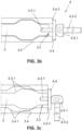
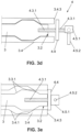
- Figures 1a and 1b show a device (10) for winding an ancillary material (21) according to a first embodiment of the present invention.
- Figure 1a schematically shows the configuration of the elements that are part of the device (10) of this embodiment when the end part (4) is uncoupled.
- Figure 1b shows this same configuration of elements when the end part (4) is coupled.
- said coupling/uncoupling of the end part (4) occurs between the second end (3.2) of the bar (3) and the connection mechanism (4.2) of the end part (4) in a coaxial manner.
- the end part (4) is a body of revolution at the end of which the connection mechanism (4.2) is located.
- the connection mechanism (4.2) is a housing adapted for inserting the second end (3.2) of the bar (3).
- the connection mechanism (4.2) is a threaded housing and the second end (3.2) of the bar (3) is also threaded to allow said coupling.
- the end part (4) comprises a reduction in section (4.1) on which the second end (2.2) of the at least one of the slats (2) is supported.
- Said reduction in section (4.1) is substantially frustoconical so as to allow the slats to slide smoothly along this reduction in section during the coupling/uncoupling of the end part.
- the slats (2) form a tubular element, defining a substantially cylindrical internal section along their entire length between their first end (2.1) and second end (2.2). Said tubular element furthermore can be divided by means of through slots (2.3) extending from the first end (2.1) to the second end (2.2), thereby forming the separation between slats (2) .
- Said slats are connected, preferably adhered, to the support mechanism (1) through an annular projection (1.1) thereof.
- Said annular projection (1.1) defines the cross-section shape of the internal section between slats in the region of the first end (2.1), being substantially circular in this particular example. Nevertheless, other cross-section shapes are allowable, such as polygonal, for example, being defined by the number, shape, and arrangement of the slats (2).
- the slats (2) when the end part (4) is uncoupled, the slats (2) remain fitted at their first end (2.1) to the support mechanism (1), and are cantilevered at their second end (2.2).
- the slats (2) are manufactured from aluminium with an anti-adhesion surface treatment.
- the device (10) includes an arm (5) attached in a rotational manner to the support mechanism (1). Therefore, the support mechanism (1) can freely turn with respect to the arm (5). This allows providing rotary motion to the whole device.
- the arm (5) is a swivel arm comprising a pressure spring (5.1).
- these slats (2) are fixed to the support mechanism (1) at their first end (2.1) and supported on the end part (4) at their second end (2.2), the slats (2) try to maintain their substantially tubular arrangement with a substantially cylindrical internal section. However, given the pressure exerted by the ancillary material (21) being wound on the slats (2), the slats (2) may bend at a certain degree and acquire the arrangement of a hyperboloid of one sheet.
- the slats (2) Upon uncoupling the connection mechanism (4.2) of the end part (4) from the second end (3.2) of the bar (3), the slats (2) are no longer supported on the end part (4) in the region of the second end (2.2). Therefore, the pressure of the ancillary material causes the bending of the slats (2) in the region of their seconds ends (2.2) and a progressive decrease in the internal section defined by the slats (2) is produced in the longitudinal direction of the bar (3).
- Figure 2 shows a second embodiment of the device (10) of the invention, wherein at least one slat is extractable.
- the at least two slats include:
- the uncoupling of the connection mechanism (4.2) of the end part (4) with respect to the bar (3) causes the movement of the at least one second slat (2.6) with respect to the at least one first slat (2.5), the second slat (2.6) thereby being extractable.
- the first slats (2.5) comprise rails on its edges adjacent to the edges of the second extractable slat (2.6).
- the extractable second slat (2.6) moves along these rails longitudinally.
- said rails serve as a guide for the movement of the at least one second slat (2.6).
- the device of this embodiment has three slats (2), particularly:
- the second slat is connected to the support mechanism (1) indirectly, by means of the fixing thereof with the end part (4).
- a suitable volume of ancillary material has been wound or the maximum storage level in the device (10) has been reached, it is then extracted.
- the end part (4) upon uncoupling the end part (4), the end part (4) is extracted together with the second extractable slat (2.6). After this, the internal section between slats is reduced due to the separation of the second slat (2.6), which facilitates extraction of the ancillary material by an operator.
- Figures 3a-3e show a device (10) configured for winding an ancillary material according to a third embodiment of the present invention.
- the bar (3) of said device (10) comprises:
- the plates (3.4) are fixed in a slidable manner to the bar (3) by means of retaining elements (3.5). Furthermore, the plates (3.4) comprise fixing means (3.4.2) configured for fixing the slats (2), so the connection of the at least two slats to the support mechanism is indirect through the bar (3) in this particular example.
- the end part (4) of the device (10) comprises:
- connection mechanism (4.2) of the end part (4) comprises a pin (4.3) comprising a first end (4.3.1) and an eye (4.3.2) at its opposite end, therefore substantially being in the form of a key.
- the first end (4.3.1) of the pin (4.3) is configured for being coupled, in a manner which can be uncoupled, with the second end (3.2) of the bar (3).
- the pin (4.3) is inserted through a hole of the pushing element (4.4), such that the pushing element (4.4) is linearly movable along the axis of the bar (3) according to the coupling of the pin (4.3).
- the pushing means comprise:
- the drive (4.5.1) is a substantially oval-shaped eccentric element.
- the coupling of the end part (4) (defined in this embodiment as the pushing of the ends (3.4.3) of the plates (3.4) towards the support mechanism) is produced by the different distance from the edges of the drive (4.5.1), which is substantially oval-shaped, to a turning axis.
- the 90° turn of the drive (4.5.1) produces a forward movement of the pushing element (4.4) of 5 mm.
- connection mechanism (4.2) of the end part (4) comprises a threaded pin (4.3) comprising a threaded end (4.3.1) configured for being coupled, in a manner which can be uncoupled, with the second end (3.2) of the bar (3).
- the threaded pin (4.3) is inserted through a hole of the pushing element (4.4), such that the pushing element (4.4) is linearly movable along the axis of the bar (3) according to the coupling of the threaded pin (4.3).
- said bar cooperates and coaxially pushes the pushing element (4.4) so it can in turn push the ends (3.4.3) of the plates (3.4) towards the support mechanism (1), causing the sliding of the inclined planes (3.4.1) of the plates (3.4) over the inclined planes (3.3.1) of the slots (3.3).
- the coupling of the end part (4) is produced in that manner in this particular example.
- the pushing means comprise a drive (4.5.1) comprising a housing for receiving a rod (4.5.2) and configured for turning integrally with the threaded pin (4.3).
- the action on the drive (4.5.1) thereby causes the pin (4.3) to be screwed into the threaded hole of the bar (3), which results in a linear motion for pushing the pushing element (4.4) as the threaded pin (4.3.1) is introduced.
- the pushing of the ends of the plates by the pushing element (4.4) results in a radial movement of the slats and in an increase in the internal section defined between slats, as described above.
- the rod (4.5.2) facilitates the turning of the drive (4.5.1).
- the uncoupling and the decrease in internal section defined between slats are achieved by means of the turning of the threaded pin (4.3) in the opposite direction, which causes the threaded pin (4.3) to become unscrewed from the bar (3) and the inclined planes of the plates and the slots to slide, also as a result of the action of the retaining elements (3.5) which try to shrink the internal section defined by the plates.
- the head itself of the threaded pin (4.3) has dimensions suitable for pushing the pushing element and is used as pushing means.
- the head of the threaded pin pushes the pushing element as the threaded pin (4.3) is screwed into the threaded hole of the bar (3), where the drive can be dispensed with.
- the slats (2) in the uncoupled state, substantially form a tubular element having a circular section and diameter of 59 mm, whereas in the coupled state they form a tubular element having a circular section and diameter of 64 mm.
- the support mechanism (1) can freely turn with respect to an arm (5) to which it is attached by means of rotational attachment.
- the arm (5) is a swivel arm comprising a pressure spring (5.1).
- Figures 4a to 4e show a system for the placement of composite material according to the invention, comprising a machine and a device.
- system (100) for the placement of composite material (22) shown in said figures comprises:
- the composite material (22) has ancillary material (21) originally adhered thereto, i.e., when it is wound on the reel (20) .
- the device (10) is configured for turning at the same linear velocity of the reel (20), in counter-rotating direction. This is by supporting and bearing both. In the preceding case, the use of variable speed drives or servo controllers is eliminated.
- the slats (2) of the device (10) are supported and roll on the reel (20), causing them both to turn at the same linear velocity in counter-rotating direction. That is, the device (10) and the reel (20) have a rolling contact point which does not slide with respect to the other, or said otherwise, the relative speed between device (10) and reel (20) at that point is 0.
- the device (10) comprises a support mechanism (1) which can freely turn with respect to an arm (5), to which it is attached by means of rotational attachment. This allows providing rotary motion to the whole device.
- the arm (5) is a swivel arm comprising a pressure spring (5.1), so the arm (5) swivels between a position where the device (10) is separated from the reel (20), and another position where both are supported at all times on one another as a result of the pressure spring (5.1).
- the machine (30) is an automatic fibre placement machine.
- FIGS. 4a to 4e schematically show the steps of the method according to the present invention.
- Said method is a method for the separation, winding, and extraction of an ancillary material (21) adhered to a sheet of composite material (22) wound on a reel (20).
- Figure 4a shows a device (10) according to any of the devices shown in Figures 1a to 3e and a reel (20). Furthermore, the connection mechanism (4.2) of the device (10) is coupled with the second end (3.2) of the bar (3) of the device (10).
- Figure 4b allows observing how the initial end of the ancillary material (21) is secured to the slats (2) of the device (10).
- said initial end is tied to one of the slats (2).
- other options such as hooking, looping, retaining, or catching, are possible.
- Figure 4c allows observing how the at least two slats (2) of the device (10) are supported on the reel (20).
- the device comprises a swivel arm (5) which furthermore comprises a pressure spring (5.1) for keeping the device (10) and the reel (20) in contact at all times.
- the system (100) comprises a machine (30) and several devices (10), which can wind ancillary material (21) wound on the same reel (20) or simultaneously, without having to perform shutdowns for the placement of composite material (22) between interchanges of the device (10) while working.
Landscapes
- Chemical & Material Sciences (AREA)
- Engineering & Computer Science (AREA)
- Composite Materials (AREA)
- Mechanical Engineering (AREA)
- Processing And Handling Of Plastics And Other Materials For Molding In General (AREA)
- Winding Of Webs (AREA)
- Extrusion Moulding Of Plastics Or The Like (AREA)
Claims (13)
- Vorrichtung (10) zum Aufwickeln eines Hilfsmaterials (21), das ursprünglich an einem auf eine Rolle (20) aufgewickelten Verbundmaterial (22) haftete, wobei die Vorrichtung (10) Folgendes umfasst:einen Stützmechanismus (1);mindestens zwei Leisten (2), die mit dem Stützmechanismus (1) verbunden und derart angeordnet sind, dass sie im Wesentlichen ein rohrförmiges Element bilden, wodurch ein interner Abschnitt zwischen ihnen definiert ist, wobei die mindestens zwei Leisten (2) ein erstes Ende (2.1) und ein zweites Ende (2.2) umfassen;einen Stab (3); undein Endteil (4);wobei der Stab (3) starr an einem ersten Ende (3.1) des Stützmechanismus (1) angebracht, in Längsrichtung entlang der Innenseite des durch die mindestens zwei Leisten (2) definierten internen Abschnitts angeordnet und dazu ausgelegt ist, an einem zweiten Ende (3.2) mit dem Endteil (4) verbunden zu sein; undwobei das Endteil (4) einen Verbindungsmechanismus (4.2) umfasst, der dazu ausgelegt ist, in einer entkoppelbaren Weise mit dem zweiten Ende (3.2) des Stabes (3) derart gekoppelt zu sein, dass in dem gekoppelten Zustand des Endteils (4) der durch die mindestens zwei Leisten (2) definierte interne Abschnitt größer ist, als er in dem entkoppelten Zustand des Endteils (4) ist;wobei die Vorrichtung (10) dadurch gekennzeichnet ist, dass sie zusätzlich einen Arm (5) umfasst, der mittels einer Drehbefestigung an dem Stützmechanismus (1) angebracht ist, wobei der Arm (5) ein Schwenkarm ist, der eine Druckfeder (5.1) umfasst, wobei in einer Einsatzsituation der Arm der Vorrichtung (10) ermöglicht, zu schwenken und jederzeit an der Rolle (20) des Verbundmaterials (22) gestützt angeordnet zu sein.
- Vorrichtung (10) nach Anspruch 1, dadurch gekennzeichnet, dass mindestens eine der Leisten (2) an dem ersten Ende (2.1) an dem Stützmechanismus (1) fixiert und an dem zweiten Ende (2.2) derart an dem Endteil (4) gestützt ist, dass die Stützung an dem Endteil (4) die Größe des durch die Leisten (2) definierten internen Abschnitts im Bereich des zweiten Endes (2.2) bestimmt.
- Vorrichtung (10) nach Anspruch 2, dadurch gekennzeichnet, dass das Endteil (4) eine Reduktion im Abschnitt (4.1) umfasst, an dem das zweite Ende (2.2) der mindestens einen der Leisten (2) gestützt ist.
- Vorrichtung (10) nach Anspruch 2 oder 3, dadurch gekennzeichnet, dass die Auslegung der Leisten (2) derart ist, dass, wenn der Verbindungsmechanismus (4.2) von dem zweiten Ende (3.2) des Stabes (3) entkoppelt ist, sich die Leisten (2) im Bereich des zweiten Endes (2.2) biegen, wodurch eine zunehmende Verringerung in dem durch die Leisten (2) definierten internen Abschnitt in der Längsrichtung des Stabes (3) erzeugt wird.
- Vorrichtung (10) nach Anspruch 1, dadurch gekennzeichnet, dass die mindestens zwei Leisten (2) mindestens eine erste Leiste (2.5), die an ihrem ersten Ende (2.1) an dem Stützmechanismus (1) fixiert ist, und mindestens eine zweite Leiste (2.6), die an ihrem zweiten Ende (2.2) an dem Endteil (4) fixiert ist, umfassen, so dass das Entkoppeln des Endteils (4) in Bezug auf den Stab (3) die Trennung der mindestens einen zweiten Leiste (2.6) in Bezug auf den Stützmechanismus (1) bewirkt.
- Vorrichtung (10) nach Anspruch 1, dadurch gekennzeichnet, dass sie mindestens zwei Platten (3.4) umfasst, und dadurch, dass der Stab (3) mindestens zwei Schlitze (3.3) parallel zu der Längsachse des Stabes (3) umfasst,wobei die mindestens zwei Schlitze (3.3) in zumindest einem Teil ihrer Erstreckung mindestens eine geneigte Ebene (3.3.1) umfassen, wobei jeder Schlitz (3.3) dazu ausgelegt ist, eine Platte (3.4) aufzunehmen,wobei jede Platte (3.4) mindestens eine geneigte Ebene (3.4.1) umfasst, die dazu ausgelegt ist, an der mindestens einen komplementären geneigten Ebene (3.3.1) des Schlitzes (3.3), der sie aufnimmt, gestützt zu sein, wobei die Platten (3.4) an dem Stab (3) in einer verschiebbaren Weise mittels Halteelementen (3.5) fixiert sind,wobei jede Leiste (2) an einer Platte (3.4) fixiert ist,wobei das Endteil (4) ein Schiebeelement (4.4), das in der Längsrichtung des Stabes (3) beweglich ist, und Schiebemittel, die dazu ausgelegt sind, das Schiebeelement (4.4) zu bewegen, umfasst,wobei• in dem entkoppelten Zustand des Endteils (4) ein Ende (3.4.3) der Platten aus den Schlitzen (3.3) hin zu dem Schiebeelement (4.4) hervorsteht, und• in dem gekoppelten Zustand des Endteils (4) das Schiebeelement (4.4) die Enden (3.4.3) der Platten (3.4) hin zu dem Stützmechanismus (1) schiebt, was das Verschieben der geneigten Ebenen (3.4.1) der Platten (3.4) über die geneigten Ebenen (3.3.1) der Schlitze (3.3) bewirkt, was eine radiale Bewegung der Leisten (2) aufgrund der gemeinsamen Wirkung der geneigten Ebenen der Platten und der Schlitze ermöglicht.
- Vorrichtung (10) nach dem vorhergehenden Anspruch, dadurch gekennzeichnet, dass das Schiebeelement (4.4) eine ringförmige Form aufweist und der Verbindungsmechanismus des Endteils (4) einen Stift (4.3) umfasst, der dazu ausgelegt ist, mit dem zweiten Ende (3.2) des Stabes (3) gekoppelt zu sein, wobei der Stift (4.3) durch das Schiebeelement (4.4) derart eingesetzt ist, dass das Schiebeelement (4.4) linear in der Längsrichtung des Stabes (3) beweglich ist.
- Vorrichtung (10) nach Anspruch 7, dadurch gekennzeichnet, dass die Schiebemittel Folgendes umfassen:▪ einen Exzenterantrieb (4.5.1), der an dem Stift (4.3) fixiert ist, mit der Fähigkeit, sich um eine Querachse in Bezug auf die Längsachse des Stabes (3) zu drehen, und umfassend ein Gehäuse zum Aufnehmen eines Stabes (4.5.2),▪ einen Stab (4.5.2), der dazu ausgelegt ist, in das Gehäuse des Antriebs (4.5.1) eingesetzt zu sein,wobei der Stab (4.5.2) zum Übertragen einer Drehbewegung auf den Antrieb (4.5.1) geeignet ist.
- Vorrichtung (10) nach Anspruch 7, dadurch gekennzeichnet, dass der Stift (4.3) ein Gewindestift ist, der eine Gewindefläche (4.3.1) in zumindest einem Abschnitt seiner Erstreckung und einen Kopf umfasst, der dazu ausgelegt ist, das Schiebeelement (4.4) zu schieben.
- Vorrichtung (10) nach einem der vorhergehenden Ansprüche, dadurch gekennzeichnet, dass die Leisten derart voneinander beabstandet angeordnet sind, dass ein Durchgangsschlitz zwischen angrenzenden Leisten vorhanden ist.
- Vorrichtung (10) nach einem der vorhergehenden Ansprüche, dadurch gekennzeichnet, dass der Verbindungsmechanismus (4.2) des Endteils (4) ein Gehäuse umfasst, das zum Einsetzen des zweiten Endes (3.2) des Stabes (3) geeignet ist, wobei vorzugsweise das zweite Ende (3.2) des Stabes (3) und das Gehäuse mit einem Gewinde versehen sind.
- System (100) zum Platzieren von auf einer Rolle (20) aufgewickeltem Verbundmaterial (22), dadurch gekennzeichnet, dass das System (100) Folgendes umfasst:▪ eine Maschine (30), vorzugsweise eine automatische Faserplatzierungsmaschine, die zum Platzieren des Verbundmaterials (22) ausgelegt ist, wobei die Maschine (30) Mittel zum Drehen der Rolle (20) in Bezug auf ihre Achse (20.1) umfasst, und▪ eine Vorrichtung (10) nach einem der Ansprüche 1 bis 11;wobei
die Maschine (30) derart ausgelegt ist, dass sie die Stützung der Vorrichtung (10) an einer in der Maschine (30) installierten Rolle (20) ermöglicht, so dass das Drehen der Rolle (20) das Drehen der Vorrichtung bei derselben Lineargeschwindigkeit und in gegenläufiger Richtung in Bezug auf die Drehrichtung der Rolle (20) bewirkt. - Verfahren zum Trennen, Aufwickeln und Entnehmen eines Hilfsmaterials (21), das an einem auf einer Rolle (20) aufgewickelten Verbundmaterial (22) haftet, dadurch gekennzeichnet, dass es die folgenden Schritte umfasst:a) Bereitstellen eines Systems (100) nach Anspruch 12 und einer Rolle (20), die aufgewickeltes Verbundmaterial (22) umfasst, wobei das Verbundmaterial (22) an einem Hilfsmaterial (21) haftet und wobei der Verbindungsmechanismus (4.2) der Vorrichtung (10) mit dem zweiten Ende (3.2) des Stabes (3) der Vorrichtung (10) gekoppelt wird,b) Befestigen des Anfangsendes des Hilfsmaterials (21) an den Leisten (2) der Vorrichtung (10),c) Stützen der Vorrichtung (10) an der Rolle (20),d) Drehen der Rolle (20) zum Platzieren des darauf aufgewickelten Verbundmaterials, wobei sich das Hilfsmaterial (21) von dem Verbundmaterial (22) trennt und das Hilfsmaterial (21) auf die Leisten (2) der Vorrichtung (10) aufgewickelt wird, bis ein Volumen von Hilfsmaterial (21) aufgewickelt ist,e) Entkoppeln des Endteils (4), um den durch die mindestens zwei Leisten (2) definierten Abschnitt zu reduzieren, undf) Entnehmen des auf die Vorrichtung (10) aufgewickelten Hilfsmaterials (21).
Applications Claiming Priority (1)
| Application Number | Priority Date | Filing Date | Title |
|---|---|---|---|
| ES201830190A ES2723983B2 (es) | 2018-02-28 | 2018-02-28 | Dispositivo para enrollar un material auxiliar, sistema de deposicion de material compuesto y metodo de separacion, enrollamiento y extraccion de un material auxiliar |
Publications (2)
| Publication Number | Publication Date |
|---|---|
| EP3533740A1 EP3533740A1 (de) | 2019-09-04 |
| EP3533740B1 true EP3533740B1 (de) | 2023-04-26 |
Family
ID=65685130
Family Applications (1)
| Application Number | Title | Priority Date | Filing Date |
|---|---|---|---|
| EP19159773.1A Active EP3533740B1 (de) | 2018-02-28 | 2019-02-27 | Vorrichtung zum aufwickeln eines zusatzmaterials, system zum platzieren von verbundmaterial und verfahren zum trennen, aufwickeln und extrahieren eines zusatzmaterials |
Country Status (3)
| Country | Link |
|---|---|
| US (1) | US20190263615A1 (de) |
| EP (1) | EP3533740B1 (de) |
| ES (1) | ES2723983B2 (de) |
Families Citing this family (7)
| Publication number | Priority date | Publication date | Assignee | Title |
|---|---|---|---|---|
| FR3132515B1 (fr) * | 2022-02-08 | 2024-04-12 | Automatismes Cg | Système d’enroulement d’un lien tel qu’une ficelle et table de déroulage utilisant un tel système d’enroulement |
| CN114535351A (zh) * | 2022-02-24 | 2022-05-27 | 云阳县国顺金属制品有限公司 | 一种钢卷放卷装置 |
| US20240124263A1 (en) * | 2022-10-13 | 2024-04-18 | NJM Packaging Inc. | Collapsible rewind spindle |
| CN115771791A (zh) * | 2022-12-29 | 2023-03-10 | 蔚来电池科技(安徽)有限公司 | 上料装置 |
| CN116986415B (zh) * | 2023-07-20 | 2025-12-12 | 西安热工研究院有限公司 | 一种用于汽轮机叶片修复的线缆收卷装置 |
| CN116924121A (zh) * | 2023-08-10 | 2023-10-24 | 速博达(深圳)自动化有限公司 | 一种卷料收料装置及卷料收料方法 |
| CN118419652B (zh) * | 2024-05-24 | 2024-11-26 | 响水巨合金属制品有限公司 | 一种304冷轧不锈钢钢卷生产用的收卷装置 |
Citations (1)
| Publication number | Priority date | Publication date | Assignee | Title |
|---|---|---|---|---|
| EP2145850A1 (de) * | 2008-07-16 | 2010-01-20 | MULTIVAC Sepp Haggenmüller GmbH & Co KG | Verpackungsmaschine mit einer Folienaufwickelvorrichtung |
Family Cites Families (9)
| Publication number | Priority date | Publication date | Assignee | Title |
|---|---|---|---|---|
| US494329A (en) * | 1893-03-28 | Spindle for paper-rolls | ||
| CH641741A5 (en) * | 1981-03-21 | 1984-03-15 | Andre Gonthier | Cylindrical reel having a retractible drum |
| EP0096494A3 (de) * | 1982-05-26 | 1984-05-09 | Norcros Investments Limited | Etikettendrucker |
| FR2601621B1 (fr) * | 1986-07-21 | 1988-11-04 | Forest Line Sa | Procede et dispositif pour la mise en forme automatique d'une nappe de fibres sur un moule ainsi que machines comportant un tel dispositif |
| DE3927915A1 (de) * | 1989-08-24 | 1991-02-28 | Schloemann Siemag Ag | Haspeldorn mit notentspreizung fuer einen bandhaspel |
| US5465922A (en) * | 1993-07-26 | 1995-11-14 | Communication Cable, Inc. | Mandrel with self-aligning flange |
| DE9402594U1 (de) * | 1994-02-17 | 1994-04-14 | CAB Produkttechnik Gesellschaft für Computer- und Automations-Bausteine mbH, 76131 Karlsruhe | Vorrichtung zum Aufwickeln und Abwickeln von bandförmigem Material |
| DE202005018808U1 (de) * | 2005-12-01 | 2007-04-12 | Avery Dennison Corp | Wickelvorrichtung mit Zentralver- und -entriegelung |
| JP4889515B2 (ja) * | 2007-01-30 | 2012-03-07 | サトーホールディングス株式会社 | リボン巻回リール |
-
2018
- 2018-02-28 ES ES201830190A patent/ES2723983B2/es active Active
-
2019
- 2019-02-27 US US16/287,071 patent/US20190263615A1/en not_active Abandoned
- 2019-02-27 EP EP19159773.1A patent/EP3533740B1/de active Active
Patent Citations (1)
| Publication number | Priority date | Publication date | Assignee | Title |
|---|---|---|---|---|
| EP2145850A1 (de) * | 2008-07-16 | 2010-01-20 | MULTIVAC Sepp Haggenmüller GmbH & Co KG | Verpackungsmaschine mit einer Folienaufwickelvorrichtung |
Also Published As
| Publication number | Publication date |
|---|---|
| ES2723983B2 (es) | 2020-02-28 |
| ES2723983A1 (es) | 2019-09-04 |
| US20190263615A1 (en) | 2019-08-29 |
| EP3533740A1 (de) | 2019-09-04 |
Similar Documents
| Publication | Publication Date | Title |
|---|---|---|
| EP3533740B1 (de) | Vorrichtung zum aufwickeln eines zusatzmaterials, system zum platzieren von verbundmaterial und verfahren zum trennen, aufwickeln und extrahieren eines zusatzmaterials | |
| KR100996123B1 (ko) | 전력저장 어셈블리 와인딩용 장치 아키텍쳐 | |
| US4909057A (en) | Apparatus and methods for continuously forming edgewise wound cores | |
| EP2519388B1 (de) | Maschine zum schneiden von rollen von bahnförmigem gut | |
| CN202089616U (zh) | 三幅板式边料回收卷绕机 | |
| JP2016510294A5 (de) | ||
| JP2692998B2 (ja) | 螺旋巻交錯可撓性パイプの製造装置 | |
| CN103708283B (zh) | 横动臂、以及具备该横动臂的纱线卷绕机 | |
| EP3683036B1 (de) | Vorrichtung und verfahren zur kontinuierlichen herstellung eines verstärkten kunststoffrohres mit einer transferfolie | |
| CN113506681B (zh) | 一种环形线圈绕线设备 | |
| KR20210113351A (ko) | 더니지 변환기를 위한 코일러 및 더니지 스트립의 코일링 방법 | |
| CN105728602A (zh) | 一种跳杆弹簧加工线及加工方法 | |
| CN1112456A (zh) | 用于中空纤维束的缠绕管、制造方法及其制造设备 | |
| CN1684873A (zh) | 用于从压紧的原材料包上去除捆线或捆带的方法以及用于实施该方法的绕线装置 | |
| CN213595570U (zh) | 预浸料斜切粘合收卷设备 | |
| UA45395C2 (uk) | Автоматичний пристрій волочіння та потокова технологічна лінія волочіння | |
| CN105336973A (zh) | 电池制作装置及电池制作方法 | |
| CN100532207C (zh) | 将已切断的捆绑材料取走的卷取装置 | |
| CN107500034B (zh) | 非晶带材自动收带装箱装置 | |
| CN107416582B (zh) | 一种碳纤维预浸丝束背衬纸剥离方法和装置 | |
| EP0104020A2 (de) | Handhabung und Behandlung einer endlosen sich bewegenden Bahn und Verfahren und Apparat zum Aufwickeln und Prägen einer solchen Bahn | |
| CN204809031U (zh) | 一种电感绕线设备 | |
| EP2188075A1 (de) | Maschine zum aufwickeln/abwickeln von schläuchen und verwandtes verfahren | |
| CN208648276U (zh) | 一种滤芯多层卷绕机 | |
| CN216335562U (zh) | 插入式自动复卷装置 |
Legal Events
| Date | Code | Title | Description |
|---|---|---|---|
| PUAI | Public reference made under article 153(3) epc to a published international application that has entered the european phase |
Free format text: ORIGINAL CODE: 0009012 |
|
| STAA | Information on the status of an ep patent application or granted ep patent |
Free format text: STATUS: THE APPLICATION HAS BEEN PUBLISHED |
|
| AK | Designated contracting states |
Kind code of ref document: A1 Designated state(s): AL AT BE BG CH CY CZ DE DK EE ES FI FR GB GR HR HU IE IS IT LI LT LU LV MC MK MT NL NO PL PT RO RS SE SI SK SM TR |
|
| AX | Request for extension of the european patent |
Extension state: BA ME |
|
| STAA | Information on the status of an ep patent application or granted ep patent |
Free format text: STATUS: REQUEST FOR EXAMINATION WAS MADE |
|
| 17P | Request for examination filed |
Effective date: 20200221 |
|
| RBV | Designated contracting states (corrected) |
Designated state(s): AL AT BE BG CH CY CZ DE DK EE ES FI FR GB GR HR HU IE IS IT LI LT LU LV MC MK MT NL NO PL PT RO RS SE SI SK SM TR |
|
| STAA | Information on the status of an ep patent application or granted ep patent |
Free format text: STATUS: EXAMINATION IS IN PROGRESS |
|
| 17Q | First examination report despatched |
Effective date: 20201030 |
|
| GRAP | Despatch of communication of intention to grant a patent |
Free format text: ORIGINAL CODE: EPIDOSNIGR1 |
|
| STAA | Information on the status of an ep patent application or granted ep patent |
Free format text: STATUS: GRANT OF PATENT IS INTENDED |
|
| RIC1 | Information provided on ipc code assigned before grant |
Ipc: B29C 70/54 20060101ALI20221102BHEP Ipc: B65H 75/24 20060101ALI20221102BHEP Ipc: B65H 54/58 20060101AFI20221102BHEP |
|
| INTG | Intention to grant announced |
Effective date: 20221121 |
|
| GRAS | Grant fee paid |
Free format text: ORIGINAL CODE: EPIDOSNIGR3 |
|
| GRAA | (expected) grant |
Free format text: ORIGINAL CODE: 0009210 |
|
| STAA | Information on the status of an ep patent application or granted ep patent |
Free format text: STATUS: THE PATENT HAS BEEN GRANTED |
|
| AK | Designated contracting states |
Kind code of ref document: B1 Designated state(s): AL AT BE BG CH CY CZ DE DK EE ES FI FR GB GR HR HU IE IS IT LI LT LU LV MC MK MT NL NO PL PT RO RS SE SI SK SM TR |
|
| REG | Reference to a national code |
Ref country code: GB Ref legal event code: FG4D |
|
| REG | Reference to a national code |
Ref country code: CH Ref legal event code: EP |
|
| REG | Reference to a national code |
Ref country code: DE Ref legal event code: R096 Ref document number: 602019027934 Country of ref document: DE |
|
| REG | Reference to a national code |
Ref country code: AT Ref legal event code: REF Ref document number: 1562699 Country of ref document: AT Kind code of ref document: T Effective date: 20230515 |
|
| REG | Reference to a national code |
Ref country code: IE Ref legal event code: FG4D |
|
| REG | Reference to a national code |
Ref country code: LT Ref legal event code: MG9D |
|
| REG | Reference to a national code |
Ref country code: NL Ref legal event code: MP Effective date: 20230426 |
|
| REG | Reference to a national code |
Ref country code: AT Ref legal event code: MK05 Ref document number: 1562699 Country of ref document: AT Kind code of ref document: T Effective date: 20230426 |
|
| PG25 | Lapsed in a contracting state [announced via postgrant information from national office to epo] |
Ref country code: NL Free format text: LAPSE BECAUSE OF FAILURE TO SUBMIT A TRANSLATION OF THE DESCRIPTION OR TO PAY THE FEE WITHIN THE PRESCRIBED TIME-LIMIT Effective date: 20230426 |
|
| PG25 | Lapsed in a contracting state [announced via postgrant information from national office to epo] |
Ref country code: SE Free format text: LAPSE BECAUSE OF FAILURE TO SUBMIT A TRANSLATION OF THE DESCRIPTION OR TO PAY THE FEE WITHIN THE PRESCRIBED TIME-LIMIT Effective date: 20230426 Ref country code: PT Free format text: LAPSE BECAUSE OF FAILURE TO SUBMIT A TRANSLATION OF THE DESCRIPTION OR TO PAY THE FEE WITHIN THE PRESCRIBED TIME-LIMIT Effective date: 20230828 Ref country code: NO Free format text: LAPSE BECAUSE OF FAILURE TO SUBMIT A TRANSLATION OF THE DESCRIPTION OR TO PAY THE FEE WITHIN THE PRESCRIBED TIME-LIMIT Effective date: 20230726 Ref country code: ES Free format text: LAPSE BECAUSE OF FAILURE TO SUBMIT A TRANSLATION OF THE DESCRIPTION OR TO PAY THE FEE WITHIN THE PRESCRIBED TIME-LIMIT Effective date: 20230426 Ref country code: AT Free format text: LAPSE BECAUSE OF FAILURE TO SUBMIT A TRANSLATION OF THE DESCRIPTION OR TO PAY THE FEE WITHIN THE PRESCRIBED TIME-LIMIT Effective date: 20230426 |
|
| PG25 | Lapsed in a contracting state [announced via postgrant information from national office to epo] |
Ref country code: RS Free format text: LAPSE BECAUSE OF FAILURE TO SUBMIT A TRANSLATION OF THE DESCRIPTION OR TO PAY THE FEE WITHIN THE PRESCRIBED TIME-LIMIT Effective date: 20230426 Ref country code: PL Free format text: LAPSE BECAUSE OF FAILURE TO SUBMIT A TRANSLATION OF THE DESCRIPTION OR TO PAY THE FEE WITHIN THE PRESCRIBED TIME-LIMIT Effective date: 20230426 Ref country code: LV Free format text: LAPSE BECAUSE OF FAILURE TO SUBMIT A TRANSLATION OF THE DESCRIPTION OR TO PAY THE FEE WITHIN THE PRESCRIBED TIME-LIMIT Effective date: 20230426 Ref country code: LT Free format text: LAPSE BECAUSE OF FAILURE TO SUBMIT A TRANSLATION OF THE DESCRIPTION OR TO PAY THE FEE WITHIN THE PRESCRIBED TIME-LIMIT Effective date: 20230426 Ref country code: IS Free format text: LAPSE BECAUSE OF FAILURE TO SUBMIT A TRANSLATION OF THE DESCRIPTION OR TO PAY THE FEE WITHIN THE PRESCRIBED TIME-LIMIT Effective date: 20230826 Ref country code: HR Free format text: LAPSE BECAUSE OF FAILURE TO SUBMIT A TRANSLATION OF THE DESCRIPTION OR TO PAY THE FEE WITHIN THE PRESCRIBED TIME-LIMIT Effective date: 20230426 Ref country code: GR Free format text: LAPSE BECAUSE OF FAILURE TO SUBMIT A TRANSLATION OF THE DESCRIPTION OR TO PAY THE FEE WITHIN THE PRESCRIBED TIME-LIMIT Effective date: 20230727 |
|
| PG25 | Lapsed in a contracting state [announced via postgrant information from national office to epo] |
Ref country code: FI Free format text: LAPSE BECAUSE OF FAILURE TO SUBMIT A TRANSLATION OF THE DESCRIPTION OR TO PAY THE FEE WITHIN THE PRESCRIBED TIME-LIMIT Effective date: 20230426 |
|
| PG25 | Lapsed in a contracting state [announced via postgrant information from national office to epo] |
Ref country code: SK Free format text: LAPSE BECAUSE OF FAILURE TO SUBMIT A TRANSLATION OF THE DESCRIPTION OR TO PAY THE FEE WITHIN THE PRESCRIBED TIME-LIMIT Effective date: 20230426 |
|
| REG | Reference to a national code |
Ref country code: DE Ref legal event code: R097 Ref document number: 602019027934 Country of ref document: DE |
|
| PG25 | Lapsed in a contracting state [announced via postgrant information from national office to epo] |
Ref country code: SM Free format text: LAPSE BECAUSE OF FAILURE TO SUBMIT A TRANSLATION OF THE DESCRIPTION OR TO PAY THE FEE WITHIN THE PRESCRIBED TIME-LIMIT Effective date: 20230426 Ref country code: SK Free format text: LAPSE BECAUSE OF FAILURE TO SUBMIT A TRANSLATION OF THE DESCRIPTION OR TO PAY THE FEE WITHIN THE PRESCRIBED TIME-LIMIT Effective date: 20230426 Ref country code: RO Free format text: LAPSE BECAUSE OF FAILURE TO SUBMIT A TRANSLATION OF THE DESCRIPTION OR TO PAY THE FEE WITHIN THE PRESCRIBED TIME-LIMIT Effective date: 20230426 Ref country code: EE Free format text: LAPSE BECAUSE OF FAILURE TO SUBMIT A TRANSLATION OF THE DESCRIPTION OR TO PAY THE FEE WITHIN THE PRESCRIBED TIME-LIMIT Effective date: 20230426 Ref country code: DK Free format text: LAPSE BECAUSE OF FAILURE TO SUBMIT A TRANSLATION OF THE DESCRIPTION OR TO PAY THE FEE WITHIN THE PRESCRIBED TIME-LIMIT Effective date: 20230426 Ref country code: CZ Free format text: LAPSE BECAUSE OF FAILURE TO SUBMIT A TRANSLATION OF THE DESCRIPTION OR TO PAY THE FEE WITHIN THE PRESCRIBED TIME-LIMIT Effective date: 20230426 |
|
| PLBE | No opposition filed within time limit |
Free format text: ORIGINAL CODE: 0009261 |
|
| STAA | Information on the status of an ep patent application or granted ep patent |
Free format text: STATUS: NO OPPOSITION FILED WITHIN TIME LIMIT |
|
| 26N | No opposition filed |
Effective date: 20240129 |
|
| PG25 | Lapsed in a contracting state [announced via postgrant information from national office to epo] |
Ref country code: SI Free format text: LAPSE BECAUSE OF FAILURE TO SUBMIT A TRANSLATION OF THE DESCRIPTION OR TO PAY THE FEE WITHIN THE PRESCRIBED TIME-LIMIT Effective date: 20230426 |
|
| PG25 | Lapsed in a contracting state [announced via postgrant information from national office to epo] |
Ref country code: SI Free format text: LAPSE BECAUSE OF FAILURE TO SUBMIT A TRANSLATION OF THE DESCRIPTION OR TO PAY THE FEE WITHIN THE PRESCRIBED TIME-LIMIT Effective date: 20230426 Ref country code: IT Free format text: LAPSE BECAUSE OF FAILURE TO SUBMIT A TRANSLATION OF THE DESCRIPTION OR TO PAY THE FEE WITHIN THE PRESCRIBED TIME-LIMIT Effective date: 20230426 |
|
| PG25 | Lapsed in a contracting state [announced via postgrant information from national office to epo] |
Ref country code: MC Free format text: LAPSE BECAUSE OF FAILURE TO SUBMIT A TRANSLATION OF THE DESCRIPTION OR TO PAY THE FEE WITHIN THE PRESCRIBED TIME-LIMIT Effective date: 20230426 |
|
| REG | Reference to a national code |
Ref country code: CH Ref legal event code: PL |
|
| PG25 | Lapsed in a contracting state [announced via postgrant information from national office to epo] |
Ref country code: LU Free format text: LAPSE BECAUSE OF NON-PAYMENT OF DUE FEES Effective date: 20240227 |
|
| PG25 | Lapsed in a contracting state [announced via postgrant information from national office to epo] |
Ref country code: CH Free format text: LAPSE BECAUSE OF NON-PAYMENT OF DUE FEES Effective date: 20240229 |
|
| PG25 | Lapsed in a contracting state [announced via postgrant information from national office to epo] |
Ref country code: LU Free format text: LAPSE BECAUSE OF NON-PAYMENT OF DUE FEES Effective date: 20240227 Ref country code: CH Free format text: LAPSE BECAUSE OF NON-PAYMENT OF DUE FEES Effective date: 20240229 |
|
| PG25 | Lapsed in a contracting state [announced via postgrant information from national office to epo] |
Ref country code: BG Free format text: LAPSE BECAUSE OF FAILURE TO SUBMIT A TRANSLATION OF THE DESCRIPTION OR TO PAY THE FEE WITHIN THE PRESCRIBED TIME-LIMIT Effective date: 20230426 |
|
| PG25 | Lapsed in a contracting state [announced via postgrant information from national office to epo] |
Ref country code: BG Free format text: LAPSE BECAUSE OF FAILURE TO SUBMIT A TRANSLATION OF THE DESCRIPTION OR TO PAY THE FEE WITHIN THE PRESCRIBED TIME-LIMIT Effective date: 20230426 |
|
| REG | Reference to a national code |
Ref country code: BE Ref legal event code: MM Effective date: 20240229 |
|
| PG25 | Lapsed in a contracting state [announced via postgrant information from national office to epo] |
Ref country code: BE Free format text: LAPSE BECAUSE OF NON-PAYMENT OF DUE FEES Effective date: 20240229 |
|
| PG25 | Lapsed in a contracting state [announced via postgrant information from national office to epo] |
Ref country code: IE Free format text: LAPSE BECAUSE OF NON-PAYMENT OF DUE FEES Effective date: 20240227 |
|
| PG25 | Lapsed in a contracting state [announced via postgrant information from national office to epo] |
Ref country code: IE Free format text: LAPSE BECAUSE OF NON-PAYMENT OF DUE FEES Effective date: 20240227 Ref country code: BE Free format text: LAPSE BECAUSE OF NON-PAYMENT OF DUE FEES Effective date: 20240229 |
|
| PG25 | Lapsed in a contracting state [announced via postgrant information from national office to epo] |
Ref country code: CY Free format text: LAPSE BECAUSE OF FAILURE TO SUBMIT A TRANSLATION OF THE DESCRIPTION OR TO PAY THE FEE WITHIN THE PRESCRIBED TIME-LIMIT; INVALID AB INITIO Effective date: 20190227 |
|
| PG25 | Lapsed in a contracting state [announced via postgrant information from national office to epo] |
Ref country code: HU Free format text: LAPSE BECAUSE OF FAILURE TO SUBMIT A TRANSLATION OF THE DESCRIPTION OR TO PAY THE FEE WITHIN THE PRESCRIBED TIME-LIMIT; INVALID AB INITIO Effective date: 20190227 |
|
| PG25 | Lapsed in a contracting state [announced via postgrant information from national office to epo] |
Ref country code: TR Free format text: LAPSE BECAUSE OF FAILURE TO SUBMIT A TRANSLATION OF THE DESCRIPTION OR TO PAY THE FEE WITHIN THE PRESCRIBED TIME-LIMIT Effective date: 20230426 |
|
| PGFP | Annual fee paid to national office [announced via postgrant information from national office to epo] |
Ref country code: GB Payment date: 20260219 Year of fee payment: 8 |
|
| PGFP | Annual fee paid to national office [announced via postgrant information from national office to epo] |
Ref country code: DE Payment date: 20260218 Year of fee payment: 8 |
|
| PGFP | Annual fee paid to national office [announced via postgrant information from national office to epo] |
Ref country code: FR Payment date: 20260218 Year of fee payment: 8 |