EP3533480B1 - Blutreinigungsvorrichtung und koppler - Google Patents
Blutreinigungsvorrichtung und koppler Download PDFInfo
- Publication number
- EP3533480B1 EP3533480B1 EP17864030.6A EP17864030A EP3533480B1 EP 3533480 B1 EP3533480 B1 EP 3533480B1 EP 17864030 A EP17864030 A EP 17864030A EP 3533480 B1 EP3533480 B1 EP 3533480B1
- Authority
- EP
- European Patent Office
- Prior art keywords
- dialysis solution
- coupler
- side coupler
- light source
- source unit
- Prior art date
- Legal status (The legal status is an assumption and is not a legal conclusion. Google has not performed a legal analysis and makes no representation as to the accuracy of the status listed.)
- Active
Links
Images

Classifications
-
- A—HUMAN NECESSITIES
- A61—MEDICAL OR VETERINARY SCIENCE; HYGIENE
- A61L—METHODS OR APPARATUS FOR STERILISING MATERIALS OR OBJECTS IN GENERAL; DISINFECTION, STERILISATION OR DEODORISATION OF AIR; CHEMICAL ASPECTS OF BANDAGES, DRESSINGS, ABSORBENT PADS OR SURGICAL ARTICLES; MATERIALS FOR BANDAGES, DRESSINGS, ABSORBENT PADS OR SURGICAL ARTICLES
- A61L2/00—Disinfection or sterilisation of materials or objects, in general; Accessories therefor
- A61L2/02—Disinfection or sterilisation of materials or objects, in general; Accessories therefor using physical processes
- A61L2/08—Radiation
- A61L2/10—Ultraviolet [UV] radiation
-
- A—HUMAN NECESSITIES
- A61—MEDICAL OR VETERINARY SCIENCE; HYGIENE
- A61M—DEVICES FOR INTRODUCING MEDIA INTO, OR ONTO, THE BODY; DEVICES FOR TRANSDUCING BODY MEDIA OR FOR TAKING MEDIA FROM THE BODY; DEVICES FOR PRODUCING OR ENDING SLEEP OR STUPOR
- A61M1/00—Suction or pumping devices for medical purposes; Devices for carrying-off, for treatment of, or for carrying-over, body-liquids; Drainage systems
- A61M1/14—Dialysis systems; Artificial kidneys; Blood oxygenators ; Reciprocating systems for treatment of body fluids, e.g. single needle systems for hemofiltration or pheresis
- A61M1/16—Dialysis systems; Artificial kidneys; Blood oxygenators ; Reciprocating systems for treatment of body fluids, e.g. single needle systems for hemofiltration or pheresis with membranes
- A61M1/168—Sterilisation or cleaning before or after use
-
- A—HUMAN NECESSITIES
- A61—MEDICAL OR VETERINARY SCIENCE; HYGIENE
- A61L—METHODS OR APPARATUS FOR STERILISING MATERIALS OR OBJECTS IN GENERAL; DISINFECTION, STERILISATION OR DEODORISATION OF AIR; CHEMICAL ASPECTS OF BANDAGES, DRESSINGS, ABSORBENT PADS OR SURGICAL ARTICLES; MATERIALS FOR BANDAGES, DRESSINGS, ABSORBENT PADS OR SURGICAL ARTICLES
- A61L2/00—Disinfection or sterilisation of materials or objects, in general; Accessories therefor
- A61L2/26—Accessories
-
- A—HUMAN NECESSITIES
- A61—MEDICAL OR VETERINARY SCIENCE; HYGIENE
- A61M—DEVICES FOR INTRODUCING MEDIA INTO, OR ONTO, THE BODY; DEVICES FOR TRANSDUCING BODY MEDIA OR FOR TAKING MEDIA FROM THE BODY; DEVICES FOR PRODUCING OR ENDING SLEEP OR STUPOR
- A61M1/00—Suction or pumping devices for medical purposes; Devices for carrying-off, for treatment of, or for carrying-over, body-liquids; Drainage systems
- A61M1/14—Dialysis systems; Artificial kidneys; Blood oxygenators ; Reciprocating systems for treatment of body fluids, e.g. single needle systems for hemofiltration or pheresis
-
- A—HUMAN NECESSITIES
- A61—MEDICAL OR VETERINARY SCIENCE; HYGIENE
- A61M—DEVICES FOR INTRODUCING MEDIA INTO, OR ONTO, THE BODY; DEVICES FOR TRANSDUCING BODY MEDIA OR FOR TAKING MEDIA FROM THE BODY; DEVICES FOR PRODUCING OR ENDING SLEEP OR STUPOR
- A61M1/00—Suction or pumping devices for medical purposes; Devices for carrying-off, for treatment of, or for carrying-over, body-liquids; Drainage systems
- A61M1/14—Dialysis systems; Artificial kidneys; Blood oxygenators ; Reciprocating systems for treatment of body fluids, e.g. single needle systems for hemofiltration or pheresis
- A61M1/16—Dialysis systems; Artificial kidneys; Blood oxygenators ; Reciprocating systems for treatment of body fluids, e.g. single needle systems for hemofiltration or pheresis with membranes
-
- A—HUMAN NECESSITIES
- A61—MEDICAL OR VETERINARY SCIENCE; HYGIENE
- A61M—DEVICES FOR INTRODUCING MEDIA INTO, OR ONTO, THE BODY; DEVICES FOR TRANSDUCING BODY MEDIA OR FOR TAKING MEDIA FROM THE BODY; DEVICES FOR PRODUCING OR ENDING SLEEP OR STUPOR
- A61M1/00—Suction or pumping devices for medical purposes; Devices for carrying-off, for treatment of, or for carrying-over, body-liquids; Drainage systems
- A61M1/14—Dialysis systems; Artificial kidneys; Blood oxygenators ; Reciprocating systems for treatment of body fluids, e.g. single needle systems for hemofiltration or pheresis
- A61M1/16—Dialysis systems; Artificial kidneys; Blood oxygenators ; Reciprocating systems for treatment of body fluids, e.g. single needle systems for hemofiltration or pheresis with membranes
- A61M1/168—Sterilisation or cleaning before or after use
- A61M1/1688—Sterilisation or cleaning before or after use with recirculation of the sterilising fluid
-
- A—HUMAN NECESSITIES
- A61—MEDICAL OR VETERINARY SCIENCE; HYGIENE
- A61M—DEVICES FOR INTRODUCING MEDIA INTO, OR ONTO, THE BODY; DEVICES FOR TRANSDUCING BODY MEDIA OR FOR TAKING MEDIA FROM THE BODY; DEVICES FOR PRODUCING OR ENDING SLEEP OR STUPOR
- A61M39/00—Tubes, tube connectors, tube couplings, valves, access sites or the like, specially adapted for medical use
- A61M39/10—Tube connectors; Tube couplings
- A61M39/16—Tube connectors; Tube couplings having provision for disinfection or sterilisation
-
- A—HUMAN NECESSITIES
- A61—MEDICAL OR VETERINARY SCIENCE; HYGIENE
- A61L—METHODS OR APPARATUS FOR STERILISING MATERIALS OR OBJECTS IN GENERAL; DISINFECTION, STERILISATION OR DEODORISATION OF AIR; CHEMICAL ASPECTS OF BANDAGES, DRESSINGS, ABSORBENT PADS OR SURGICAL ARTICLES; MATERIALS FOR BANDAGES, DRESSINGS, ABSORBENT PADS OR SURGICAL ARTICLES
- A61L2202/00—Aspects relating to methods or apparatus for disinfecting or sterilising materials or objects
- A61L2202/10—Apparatus features
- A61L2202/11—Apparatus for generating biocidal substances, e.g. vaporisers, UV lamps
-
- A—HUMAN NECESSITIES
- A61—MEDICAL OR VETERINARY SCIENCE; HYGIENE
- A61L—METHODS OR APPARATUS FOR STERILISING MATERIALS OR OBJECTS IN GENERAL; DISINFECTION, STERILISATION OR DEODORISATION OF AIR; CHEMICAL ASPECTS OF BANDAGES, DRESSINGS, ABSORBENT PADS OR SURGICAL ARTICLES; MATERIALS FOR BANDAGES, DRESSINGS, ABSORBENT PADS OR SURGICAL ARTICLES
- A61L2202/00—Aspects relating to methods or apparatus for disinfecting or sterilising materials or objects
- A61L2202/10—Apparatus features
- A61L2202/17—Combination with washing or cleaning means
-
- A—HUMAN NECESSITIES
- A61—MEDICAL OR VETERINARY SCIENCE; HYGIENE
- A61M—DEVICES FOR INTRODUCING MEDIA INTO, OR ONTO, THE BODY; DEVICES FOR TRANSDUCING BODY MEDIA OR FOR TAKING MEDIA FROM THE BODY; DEVICES FOR PRODUCING OR ENDING SLEEP OR STUPOR
- A61M2205/00—General characteristics of the apparatus
- A61M2205/14—Detection of the presence or absence of a tube, a connector or a container in an apparatus
-
- A—HUMAN NECESSITIES
- A61—MEDICAL OR VETERINARY SCIENCE; HYGIENE
- A61M—DEVICES FOR INTRODUCING MEDIA INTO, OR ONTO, THE BODY; DEVICES FOR TRANSDUCING BODY MEDIA OR FOR TAKING MEDIA FROM THE BODY; DEVICES FOR PRODUCING OR ENDING SLEEP OR STUPOR
- A61M2205/00—General characteristics of the apparatus
- A61M2205/33—Controlling, regulating or measuring
- A61M2205/3331—Pressure; Flow
- A61M2205/3334—Measuring or controlling the flow rate
-
- A—HUMAN NECESSITIES
- A61—MEDICAL OR VETERINARY SCIENCE; HYGIENE
- A61M—DEVICES FOR INTRODUCING MEDIA INTO, OR ONTO, THE BODY; DEVICES FOR TRANSDUCING BODY MEDIA OR FOR TAKING MEDIA FROM THE BODY; DEVICES FOR PRODUCING OR ENDING SLEEP OR STUPOR
- A61M2205/00—General characteristics of the apparatus
- A61M2205/82—Internal energy supply devices
- A61M2205/8206—Internal energy supply devices battery-operated
-
- A—HUMAN NECESSITIES
- A61—MEDICAL OR VETERINARY SCIENCE; HYGIENE
- A61M—DEVICES FOR INTRODUCING MEDIA INTO, OR ONTO, THE BODY; DEVICES FOR TRANSDUCING BODY MEDIA OR FOR TAKING MEDIA FROM THE BODY; DEVICES FOR PRODUCING OR ENDING SLEEP OR STUPOR
- A61M2209/00—Ancillary equipment
- A61M2209/08—Supports for equipment
-
- A—HUMAN NECESSITIES
- A61—MEDICAL OR VETERINARY SCIENCE; HYGIENE
- A61M—DEVICES FOR INTRODUCING MEDIA INTO, OR ONTO, THE BODY; DEVICES FOR TRANSDUCING BODY MEDIA OR FOR TAKING MEDIA FROM THE BODY; DEVICES FOR PRODUCING OR ENDING SLEEP OR STUPOR
- A61M2209/00—Ancillary equipment
- A61M2209/10—Equipment for cleaning
Definitions
- the present invention relates to a blood purification device, and, more particularly, to a coupler connected to a joint pipe of a blood purifier.
- a blood purifier called a dialyzer
- a dialysis solution inflow pipe and a dialysis solution outflow pipe are provided in the blood purifier.
- a tube for supplying a dialysis solution is detachably connected to the dialysis solution inflow pipe via a coupler, and a tube for discharging a dialysis solution is detachably connected to the dialysis solution outflow pipe via a coupler.
- the couplers on the supply side and the discharge side are detached from the blood purifier, and the route in which the dialysis solution flows is cleaned or sterilized by connecting the couplers to each other (see, for example, patent document 1).
- connection part of the coupler that comes into contact with the dialysis solution inflow pipe or the dialysis solution outflow pipe has a female connector shape so that it might be difficult to clean or sterilize the connection part by wiping it with alcohol, etc.
- an illustrative purpose of the present invention is to provide a technology of sterilizing the interior of a coupler connected to a blood purifier.
- a blood purification device comprises the technical features as defined in independent claim 1.
- a blood purification device includes: a control device that controls supply of a dialysis solution to a blood purifier; a dialysis solution supply tube in which the dialysis solution flows from the control device toward the blood purifier; a dialysis solution discharge tube in which the dialysis solution flows from the blood purifier toward the control device; a supply side coupler that connects between the dialysis solution supply tube and a dialysis solution inflow pipe of the blood purifier; and a discharge side coupler that connects between the dialysis solution discharge tube and a dialysis solution outflow pipe of the blood purifier.
- At least one of the supply side coupler and the discharge side coupler includes a light source unit configured to irradiate an interior of the coupler with ultraviolet light.
- the interior of the coupler connected to the blood purifier is sterilized by irradiating the interior of the coupler with ultraviolet light. This maintains the coupler in a sanitized condition.
- the supply side coupler may include a pipe connection part detachably connected to the dialysis solution inflow pipe.
- the discharge side coupler may include a pipe connection part detachably connected to the dialysis solution outflow pipe.
- the light source unit may be configured to irradiate the pipe connection part exposed by being detached from the dialysis solution inflow pipe or the dialysis solution outflow pipe with ultraviolet light.
- the control device may be configured to perform a cleaning process of circulating a cleaning solution in a route passing through the dialysis solution supply tube, the supply side coupler, the discharge side coupler, and the dialysis solution discharge tube while the supply side coupler detached from the dialysis solution inflow pipe and the discharge side coupler detached from the dialysis solution outflow pipe are connected to each other.
- the light source unit may radiate ultraviolet light while the cleaning process is being performed.
- the control device includes a coupler holder configured to temporarily hold the supply side coupler detached from the dialysis solution inflow pipe and the discharge side coupler detached from the dialysis solution outflow pipe.
- the light source unit includes a power reception unit configured to receive power from the control device while the supply side coupler and the discharge side coupler are being held by the coupler holder.
- the power reception unit may be configured to receive power from the control device in a contactless scheme.
- the light source unit may be configured not to be lighted when the light source unit is detached from the coupler holder.
- the light source unit may irradiate the dialysis solution flowing inside the coupler with ultraviolet light while a dialytic process of supplying the dialysis solution to the blood purifier is being performed.
- the light source unit may be configured to be detachable from a main part of the supply side coupler or the discharge side coupler.
- a main part of at least one of the supply side coupler and the discharge side coupler may be provided with a window member that transmits ultraviolet light from the light source unit.
- At least one of the supply side coupler and the discharge side coupler may include a main part, a pipe connection part adjacent to the main part in an axial direction, and a tube connection part extending from the main part in a direction perpendicular to the axial direction so as to form an L shape.
- the light source unit may be configured to radiate ultraviolet light in the axial direction from the main part toward the pipe connection part.
- the coupler is for connecting between a dialysis solution tube for supplying or discharging a dialysis solution and a joint pipe of a blood purifier, comprising a light source unit configured to irradiate an interior of the coupler with ultraviolet light.
- the interior of the coupler connected to the blood purifier is sterilized by irradiating the interior of the coupler with ultraviolet light. This maintains the coupler in a sanitized condition.
- the interior of the coupler is sterilized by ultraviolet irradiation.
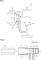
- Fig. 1 schematically shows a configuration of a blood purification device 10 according to the embodiment.
- the blood purification device 10 includes a supply side coupler 30a, a discharge side coupler 30b, a control device 50, a dialysis solution supply tube 66, a dialysis solution discharge tube 68.
- the blood purification device 10 is a system for performing a blood purification process such as blood dialysis and purifies the blood circulating inside a body by using a blood purifier 20 called a dialyzer.
- the blood purification device 10 is detachably connected to the blood purifier 20 via the supply side coupler 30a and the discharge side coupler 30b.
- the blood purifier 20 includes a blood inflow port 22, a blood outflow port 24, a dialysis solution inflow pipe 26, and a dialysis solution outflow pipe 28.
- the blood inflow port 22 is connected to an arterial blood circuit 12, and the blood outflow port 24 is connected to an intravenous blood circuit 14.
- the dialysis solution inflow pipe 26 is connected to the dialysis solution supply tube 66 via the supply side coupler 30a, and the dialysis solution supplied from the control device 50 flows into the dialysis solution inflow pipe 26.
- the dialysis solution outflow pipe 28 is connected to the dialysis solution discharge tube 68 via the discharge side coupler 30b, and the dialysis solution discharged toward the control device 50 flows out of the dialysis solution outflow pipe 28.
- the blood purifier 20 contains hollow fibers inside, and the interior of the hollow fibers serves as a flow passage of the blood connecting the blood inflow port 22 and the blood outflow port 24. Meanwhile, the exterior of the hollow fibers serves as a flow passage for the dialysis solution connecting the dialysis solution inflow pipe 26 and the dialysis solution outflow pipe 28.
- a large number of bores are formed in the hollow fibers, and the hollow fibers are configured to permeate the waste matter, excess moisture, etc. in the blood via the large number of bores.
- An unused blood purifier 20 is used for each session of dialytic treatment of a patient and is exchanged at each dialytic process.
- the supply side coupler 30a connects between the dialysis solution inflow pipe 26 and the dialysis solution supply tube 66.
- the discharge side coupler 30b connects between the dialysis solution outflow pipe 28 and the dialysis solution discharge tube 68.
- the supply side coupler 30a and the discharge side coupler 30b are so-called one-touch couplers and have a female connector structure.
- the supply side coupler 30a is detachably connected to the dialysis solution inflow pipe 26 by, for example, manipulating a slide member provided on the outer circumference of the supply side coupler 30a.
- the discharge side coupler 30b is detachably connected to the dialysis solution outflow pipe 28 by, for example, manipulating a slide member provided on the outer circumference of the discharge side coupler 30b.
- Fig. 2 is a cross-sectional view schematically showing a configuration of the coupler 30 (the supply side coupler 30a or the discharge side coupler 30b).
- the supply side coupler 30a and the discharge side coupler 30b have a similar structure so that these may be generically referred to as the "coupler 30".
- the coupler 30 includes a main part 32, a pipe connection part 34, a tube connection part 36, a window member 38, and a light source unit 40.
- the coupler 30 is configured such that the main part 32, the pipe connection part 34, and the tube connection part 36 form an L shape.
- the pipe connection part 34 is adjacent to the main part 32 in the axial direction and form a first flow passage 33 extending in the axial direction along with the main part 32.
- the tube connection part 36 extends from the main part 32 in a direction perpendicular to or intersecting the axial direction.
- the tube connection part 36 forms a second flow passage 37 extending to form an L shape as a bent extension from the first flow passage 33 extending in the axial direction.
- the pipe connection part 34 is a part detachably connected to the dialysis solution inflow pipe 26 or the dialysis solution outflow pipe 28, which are joint pipes of the blood purifier 20.
- the pipe connection part 34 has a female connector structure.
- An inner surface 35 of the pipe connection part 34 and the outer circumference of the joint pipe (the dialysis solution inflow pipe 26 or the dialysis solution outflow pipe 28) are in contact or engaged with each other to establish connection.
- the tube connection part 36 is a part connected to an end of the dialysis solution supply tube 66 or the dialysis solution discharge tube 68. By being inserted into an end of the dialysis solution supply tube 66 or the dialysis solution discharge tube 68, the tube connection part 36 is connected to the tube.
- the window member 38 is provided in the main part 32 and is arranged to transmit ultraviolet light from the light source unit 40 in the axial direction.
- the window member 38 is preferably made of a material having a high ultraviolet transmittance and is made of quartz (SiO 2 ), sapphire (Al 2 O 3 ), amorphous fluororesin, or the like.
- the light source unit 40 is provided adjacent to the window member 38 and is fixed to the main part 32.
- the light source unit 40 is attached to the main part 32 detachably or in a manner that it is easily detached.
- the light source unit 40 includes a light emitting device 42, a power reception unit 44, and a housing 46.
- the light emitting device 42 and the power reception unit 44 are housed inside the housing 46.
- the light emitting devices 42 is a so-called ultra violet-light emitting diode (UV-LED) and outputs ultraviolet light having a central wavelength or a peak wavelength included in a range of about 200 nm ⁇ 350 nm. It is preferred that the light emitting device 42 emit ultraviolet light near 260 nm ⁇ 290 nm having a high sterilizing efficiency.
- UV-LED ultra violet-light emitting diode
- Such a deep ultraviolet LED is exemplified by an aluminum gallium nitride (AlGaN) based LED.
- the power reception unit 44 is configured to receive power supplied from outside the light source unit 40.
- the power reception unit 44 is configured to receiver power in a so-called contactless scheme.
- the power reception unit 44 includes a coil, etc. for receiving power transmitted by using electromagnetic waves.
- the power reception unit 44 may be configured to receive power in a contact scheme and may include a metal terminal for receiving power.
- the power reception unit 44 is configured to supply power to the light emitting device 42.
- the power reception unit 44 includes a circuit to drive the light source unit 40.
- the power reception unit 44 may not include a circuit to drive the light source unit 40, and the received power may be directly supplied to the light source unit 40.
- the power reception unit 44 may include a power storage unit for temporarily storing the power that should be supplied to the light emitting device 42.
- the power storage unit included in the power reception unit 44 may be comprised of a secondary battery that can be charged and discharged.
- the light source unit 40 is configured to irradiate the interior of the main part 32 and the pipe connection part 34 of the coupler 30 with ultraviolet light.
- the light source unit 40 radiates ultraviolet light in the axial direction along the first flow passage 33 to irradiate the inner side of the main part 32 and the pipe connection part 34 with ultraviolet light.
- the light source unit 40 irradiates the inner surface 35 of the pipe connection part 34 configured to come into contact with the the dialysis solution inflow pipe 26 or the dialysis solution outflow pipe 28 so that the inner surface 35 is sterilized or disinfected.
- the coupler 30 is made of, for example, a resin material. It is preferred that the coupler 30 be made of a material having a high durability against deep ultraviolet light.
- the coupler 30 is made of a fluororesin such as polytetrafluoroethylene (PTFE).
- PTFE polytetrafluoroethylene
- At least the inner surface 35 of the coupler 30 may be made of a material having a high ultraviolet reflectivity (e.g., PTFE).
- the control device 50 is configured to control the supply of the dialysis solution to and the discharge of the dialysis solution from the blood purifier 20.
- the control device 50 includes a dialysis solution supply port 56 connected to the dialysis solution supply tube 66 and a dialysis solution discharge port 58 connected to the dialysis solution discharge tube 68.
- the control device 50 includes a pump (not shown) for supplying and discharging the dialysis solution and controls the flow of the dialysis solution to the blood purifier 20 by controlling the operation of the pump.
- the control device 50 includes a coupler holder 52.
- the coupler holder 52 is provided to hold the supply side coupler 30a and the discharge side coupler 30b temporarily while the blood purifier 20 is not being used.
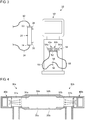
- Fig. 3 schematically shows how the couplers 30a, 30b are held by the coupler holder 52. While the blood purifier 20 is not being used, the supply side coupler 30a and the discharge side coupler 30b are detached from the blood purifier 20 and the openings thereof are connected to each other. While the supply side coupler 30a and the discharge side coupler 30b are connected, the coupler holder 52 temporarily holds or engages both of the couplers 30a, 30b.
- the supply side coupler 30a and the discharge side coupler 30b may be connected to each other via a dedicated adaptor or connector. Alternatively, the supply side coupler 30a and the discharge side coupler 30b may be configured such that they can be directly connected.
- a continuous circulation route passing through the dialysis solution supply port 56, the dialysis solution supply tube 66, the supply side coupler 30a, the discharge side coupler 30b, the dialysis solution discharge tube 68, and the dialysis solution discharge port 58 is built.
- a cleaning solution for cleaning the interior of the tubes and the couplers forming the route is circulated in the circulation route.
- the control device 50 performs a cleaning process of circulating the cleaning solution while the supply side coupler 30a and the discharge side coupler 30b are connected.
- the cleaning solution circulated for cleaning is not limited to a particular type.
- Water e.g., pure water
- an antiseptic solution such as an aqueous solution of sodium hypochlorite and an acetyl hydroperoxide solution, or a dialysis solution can be used as the cleaning solution.
- the control device 50 includes a power feeding unit 54.
- the power feeding unit 54 feeds power to the power reception unit 44 of the couplers 30a, 30b held by the coupler holder 52.
- the power feeding unit 54 includes a first power feeding unit 54a for supplying power to one of the couplers 30a, 30b and a second power feeding unit 54b for supplying power to the other of the couplers 30a, 30b.
- the first power feeding unit 54a and the second power feeding unit 54b are provided in the neighborhood of the light source unit 40 (the power reception unit 44) of the couplers 30a, 30b held by the coupler holder 52.
- the power feeding unit 54 includes a coil, etc. for supplying power in a contactless scheme.
- the power feeding unit 54 may include a power feeding terminal for supplying power in a contact scheme.
- Fig. 4 is a cross-sectional view schematically showing the couplers 30a, 30b that are being cleaned.
- the openings of the pipe connection parts 34a, 34b of the couplers 30a, 30b are connected to each other, and the first flow passages 33a, 33b of the couplers form a single flow passage extending in the axial direction.
- the light source units 40a, 40b face each other in the axial direction, sandwiching the first flow passages 33a, 33b and emit ultraviolet light in the axial direction. This causes the interior of the main parts 32a, 32b of the couplers and the inner surfaces 35a, 35b of the pipe connection parts 34a, 34b of the couplers to be sterilized by ultraviolet irradiation.
- the light source units 40 may be configured to radiate ultraviolet light only while the couplers are held by the coupler holder 52.
- the light source units 40 may be configured to be lighted only while power is being fed from the power feeding unit 54.
- the light source units 40 may be configured not to be lighted while power is not being fed from the power feeding unit 54 and configured not to be lighted when the light source units 40 are detached from the coupler holder 52. This prevents the ultraviolet light from the light source units 40 from leaking outside when the coupler 30 is attached to the blood purifier 20.
- the interior of the couplers 30a, 30b, detached from the blood purifier 20 when a dialytic process is not performed, can be sterilized with ultraviolet light by connecting the couplers 30a, 30b and placing the couplers 30a, 30b in the coupler holder 52.
- power is fed to the light source unit 40 of the coupler 30 in a contactless scheme so that it is not necessary to expose a metallic component such as a power supply terminal to the light source unit 40.
- the coupler 30 comes into contact with the dialysis solution. If a metallic component is exposed, therefore, it may become rusty easily and present a sanitary problem.
- power is fed in a contactless scheme so that it is easy to maintain the coupler 30 in a sanitized condition.
- the light source unit 40 is configured to be detachable from the main part 32 of the coupler 30 so that the maintainability of the coupler 30 is improved. For example, when a trouble occurs in the light source unit 40, only the light source unit 40 may be replaced. Further, only the connector structure of the coupler 30, including the main part 32, may be replaced, and the previous light source unit 40 may be attached to the new main part 32. This decreases the cost incurred for maintenance as compared with the case of replacing the entirety of the coupler 30.
- the light source unit 40 is provided in both the supply side coupler 30a and the discharge side coupler 30b. In a variation, the light source unit 40 is provided only in one of the supply side coupler 30a and the discharge side coupler 30b, and the light source unit 40 may not be provided in the other.
- Fig. 5 is a cross-sectional view schematically showing couplers 70a, 30b according to a variation.
- the supply side coupler 70a that does not include the light source unit 40 is used in place of the supply side coupler 30a.
- the supply side coupler 70a includes a main part 72, a pipe connection part 74, and a tube connection part 76. As shown in the figure, the supply side coupler 70a is connected to the discharge side coupler 30b during a cleaning process.
- the interior of the main part 72 and an inner surface 75 of the pipe connection part 74 of the supply side coupler 70a are sterilized by ultraviolet irradiation from the light source unit 40b of the discharge side coupler 30b.
- the variation also allows the interior of the couplers 70a, 30b to be sterilized by ultraviolet light.
- the light source unit 40 may be provided in the supply side coupler 30a, and the light source unit 40 may not be provided in the discharge side coupler.
- the light source unit 40 is described as radiating ultraviolet during a cleaning process.
- the light source unit 40 may radiate ultraviolet light while a dialytic process is being performed.
- the light source unit 40 may be lighted by using power collected in the power reception unit 44 or may be lighted by using power supplied via a power supply cable connected to the light source unit 40.
- the power supply cable may be provided in the dialysis solution supply tube 66 or the dialysis solution discharge tube 68.
- the power supply cable may be formed to be integrated with the dialysis solution supply tube 66 or the dialysis solution discharge tube 68.
- the coupler 30 is described as having an L shape.
- the coupler on the dialysis solution side may have a straight shape.
- a window member may be provided in a portion of the outer circumference of the coupler, and the light source unit may be attached to outer circumference of the coupler so as to irradiate the interior of the coupler with ultraviolet light.
- 10 ... blood purification device, 20 ... blood purifier, 26 ... dialysis solution inflow pipe, 28 ... dialysis solution outflow pipe, 30 ... coupler, 30a ... supply side coupler, 30b ... discharge side coupler, 32 ... main part, 34 ... pipe connection part, 36 ... tube connection part, 38 ... window member, 40 ... light source unit, 44 ... power reception unit, 50 ... control device, 52 ... coupler holder, 66 ... dialysis solution supply tube, 68 ... dialysis solution discharge tube
- the interior of the coupler is sterilized by ultraviolet irradiation.
Landscapes
- Health & Medical Sciences (AREA)
- Heart & Thoracic Surgery (AREA)
- Veterinary Medicine (AREA)
- Public Health (AREA)
- General Health & Medical Sciences (AREA)
- Animal Behavior & Ethology (AREA)
- Life Sciences & Earth Sciences (AREA)
- Urology & Nephrology (AREA)
- Hematology (AREA)
- Biomedical Technology (AREA)
- Anesthesiology (AREA)
- Engineering & Computer Science (AREA)
- Epidemiology (AREA)
- Vascular Medicine (AREA)
- Emergency Medicine (AREA)
- Pulmonology (AREA)
- External Artificial Organs (AREA)
- Apparatus For Disinfection Or Sterilisation (AREA)
Claims (8)
- Blutreinigungsvorrichtung (10), umfassend:eine Steuervorrichtung (50), die die Zufuhr einer Dialyselösung zu einem Blutreiniger (20) steuert;ein Dialyselösung-Zuführungsschlauch (66), in dem die Dialyselösung von der Steuervorrichtung (50) zum Blutreiniger (20) fließt;ein Dialyselösung-Abgabeschlauch (68), in dem die Dialyselösung vom Blutreiniger (20) zur Steuervorrichtung (50) fließt;ein zufuhrseitiger Koppler (30a), der zwischen dem Dialyselösung-Zuführungsschlauch (66) und einem Dialyselösung-Zuflussrohr (26) des Blutreinigers (20) angebracht ist; undein abgabeseitiger Koppler (30b), der zwischen dem Dialyselösung-Abgabeschlauch (68) und einem Dialyselösung-Abflussrohr (28) des Blutreinigers (20) angebracht ist, wobeidie Steuervorrichtung (50) eine Kopplerhalterung (52) aufweist, die zum temporären Halten des zufuhrseitigen Kopplers (30a), der vom Dialyselösung-Zuflussrohr (26) gelöst ist, und des abgabeseitigen Kopplers (30b), der vom Dialyselösung-Abflussrohr (28) gelöst ist, ausgelegt ist,dadurch gekennzeichnet, dasszumindest der zufuhrseitige Koppler (30a) und/oder der abgabeseitige Koppler (30b) eine Lichtquelleneinheit (40, 40a, 40b) aufweist, die zur Bestrahlung eines Innenraums des Kopplers (30a, 30b) mit ultraviolettem Licht ausgelegt ist, wobei die Lichtquelleneinheit (40, 40a, 40b) eine Stromaufnahmeeinheit (44) aufweist, die dazu ausgelegt ist, Strom von der Steuervorrichtung (50) auf kontaktlose Weise oder auf kontaktierende Weise zu empfangen, während der zufuhrseitige Koppler (30a) und der abgabeseitige Koppler (30b) von der Kopplerhalterung (52) festgehalten werden, und keinen Strom von der Steuervorrichtung (50) zu empfangen, während der zufuhrseitige Koppler (30a) und der abgabeseitige Koppler (30b) von der Kopplerhalterung (52) gelöst sind.
- Blutreinigungsvorrichtung nach Anspruch 1, wobei
der zufuhrseitige Koppler (30a) einen Rohrverbindungsteil (34) aufweist, der lösbar mit dem Dialyselösung-Zuflussrohr verbunden ist,
der abgabeseitige Koppler (30b) einen Rohrverbindungsteil (34) aufweist, der lösbar mit dem Dialyselösung-Abflussrohr verbunden ist, und
die Lichtquelleneinheit (40, 40a, 40b) zur Bestrahlung des Rohrverbindungsteils, der freigelegt wird, indem er vom Dialyselösung-Zuflussrohr (26) oder dem Dialyselösung-Abflussrohr (28) gelöst wird, mit ultravioletten Licht ausgelegt ist. - Blutreinigungsvorrichtung nach einem von Anspruch 1 oder 2, wobei
die Steuervorrichtung zur Durchführung eines Reinigungsverfahrens mit Zirkulation einer Reinigungslösung auf einem durch den Dialyselösung-Zuführungsschlauch, den zufuhrseitigen Koppler, den abgabeseitigen Koppler und den Dialyselösung-Abgabeschlauch führenden Weg ausgelegt ist, während der vom Dialyselösung-Zuflussrohr gelöste zufuhrseitige Koppler und der vom Dialyselösung-Abflussrohr gelöste abgabeseitige Koppler miteinander verbunden sind, und
die Lichtquelleneinheit ultraviolettes Licht ausstrahlt, während das Reinigungsverfahren durchgeführt wird. - Blutreinigungsvorrichtung nach einem der Ansprüche 1 bis 3, wobei die Lichtquelleneinheit dazu ausgelegt ist, beleuchtet zu sein, wenn der zufuhrseitige Koppler (30a) und der abgabeseitige Koppler (30b) von der Kopplerhalterung festgehalten werden, und nicht beleuchtet zu sein, wenn der zufuhrseitige Koppler (30a) und der abgabeseitige Koppler (30b) von der Kopplerhalterung gelöst sind.
- Blutreinigungsvorrichtung nach einem der Ansprüche 1 bis 3, wobei
die Stromaufnahmeeinheit 44 der Lichtquelleneinheit (40) eine Stromspeichereinheit aufweist, die zur Zuführung von temporär gespeichertem Strom zu einer Lichtabgabevorrichtung (42) der Lichtquelleneinheit (40) ausgelegt ist. - Blutreinigungsvorrichtung nach einem der Ansprüche 1 bis 5, wobei
die Lichtquelleneinheit dazu ausgelegt ist, von einem Hauptteil (32) des zufuhrseitigen Kopplers oder des abgabeseitigen Kopplers lösbar zu sein. - Blutreinigungsvorrichtung nach einem der Ansprüche 1 bis 6, wobei
ein Hauptteil (32) zumindest des zufuhrseitigen Kopplers und/oder des abgabeseitigen Kopplers ein Fensterelement (38) aufweist, das ultraviolettes Licht von der Lichtquelleneinheit überträgt. - Blutreinigungsvorrichtung nach einem der Ansprüche 1 bis 7, wobei
zumindest der zufuhrseitige Koppler und/oder der abgabeseitige Koppler einen Hauptteil (32), einen Rohrverbindungsteil (34) neben dem Hauptteil in einer axialen Richtung und einen Schlauchverbindungsteil (36), der sich vom Hauptteil in einer zur axialen Richtung senkrechen Richtung zur Bildung einer L-Form erstreckt, aufweist, und
die Lichtquelleneinheit dazu ausgelegt ist, ultraviolettes Licht in der axialen Richtung vom Hauptteil zum Rohrverbindungsteil auszustrahlen.
Applications Claiming Priority (2)
| Application Number | Priority Date | Filing Date | Title |
|---|---|---|---|
| JP2016208979A JP6393725B2 (ja) | 2016-10-25 | 2016-10-25 | 血液浄化装置およびカプラ |
| PCT/JP2017/037847 WO2018079406A1 (ja) | 2016-10-25 | 2017-10-19 | 血液浄化装置およびカプラ |
Publications (3)
| Publication Number | Publication Date |
|---|---|
| EP3533480A1 EP3533480A1 (de) | 2019-09-04 |
| EP3533480A4 EP3533480A4 (de) | 2020-06-03 |
| EP3533480B1 true EP3533480B1 (de) | 2021-06-16 |
Family
ID=62024765
Family Applications (1)
| Application Number | Title | Priority Date | Filing Date |
|---|---|---|---|
| EP17864030.6A Active EP3533480B1 (de) | 2016-10-25 | 2017-10-19 | Blutreinigungsvorrichtung und koppler |
Country Status (5)
| Country | Link |
|---|---|
| US (1) | US11850343B2 (de) |
| EP (1) | EP3533480B1 (de) |
| JP (1) | JP6393725B2 (de) |
| CN (1) | CN109890432A (de) |
| WO (1) | WO2018079406A1 (de) |
Families Citing this family (5)
| Publication number | Priority date | Publication date | Assignee | Title |
|---|---|---|---|---|
| CN113164635A (zh) * | 2018-11-02 | 2021-07-23 | 恩普乐股份有限公司 | 紫外线照射单元及紫外线杀菌装置 |
| EP4127126A4 (de) * | 2020-03-24 | 2025-01-22 | Colorado State University Research Foundation | Photoreaktorvorrichtungen, systeme und verfahren zur verwendung davon |
| US11305032B2 (en) * | 2020-05-29 | 2022-04-19 | Stanley W. Ellis | Ultraviolet air irradiation system and ultraviolet air irradiation process |
| US12115295B2 (en) * | 2021-12-20 | 2024-10-15 | Fresenius Medical Care Holdings, Inc. | Hemodialysis system including ultraviolet chamber(s) |
| US11850342B2 (en) | 2022-03-21 | 2023-12-26 | Fresenius Medical Care Holdings, Inc. | Securing connections to dialyzers |
Family Cites Families (17)
| Publication number | Priority date | Publication date | Assignee | Title |
|---|---|---|---|---|
| US4141686A (en) * | 1977-03-24 | 1979-02-27 | Lewis James H | Disposable liquid sterilizer unit |
| JP2758148B2 (ja) | 1995-08-14 | 1998-05-28 | 日機装株式会社 | 血液浄化器用カプラ |
| JP2002219169A (ja) * | 2001-01-26 | 2002-08-06 | Masakatsu Kameda | 酸化チタンコーティングを目的とする、人工透析医療用透明ポリカーボネイト樹脂製カプラ |
| JP4286073B2 (ja) * | 2003-06-18 | 2009-06-24 | ニプロ株式会社 | 透析器接続用カプラ |
| EP1488826A1 (de) * | 2003-06-19 | 2004-12-22 | Nipro Corporation | Verbindungsdichtung für Dialysatoranschluss |
| US7410579B2 (en) * | 2005-01-05 | 2008-08-12 | Alcavis International, Inc. | Manual dialyzer header cleaning device |
| US8197087B2 (en) * | 2007-07-05 | 2012-06-12 | Baxter International Inc. | Peritoneal dialysis patient connection system using ultraviolet light emitting diodes |
| JP5294972B2 (ja) * | 2009-05-13 | 2013-09-18 | 東レ・メディカル株式会社 | 血液透析装置におけるカプラ保持装置 |
| JP5205496B2 (ja) * | 2011-07-27 | 2013-06-05 | 日機装株式会社 | 透析液取出装置 |
| US9295742B2 (en) * | 2012-04-16 | 2016-03-29 | Puracath Medical, Inc. | System and method for disinfecting a catheter system |
| JP5734262B2 (ja) * | 2012-11-14 | 2015-06-17 | 日機装株式会社 | 血液浄化システム |
| CN103830756B (zh) * | 2012-11-20 | 2019-02-12 | 广州市暨华医疗器械有限公司 | 血液透析机的消毒液吸入方法及系统 |
| ES2708799T3 (es) * | 2013-12-18 | 2019-04-11 | Maria Patricia Cohen | Esterilización con UV de catéteres y conectores de catéter |
| JP2018513720A (ja) * | 2015-03-18 | 2018-05-31 | プラキャス メディカル インコーポレイテッド | 紫外線殺菌のためのカテーテル接続システム |
| CN205126917U (zh) * | 2015-10-30 | 2016-04-06 | 南昌大学第一附属医院 | 腹膜透析消毒清洁仓 |
| EP3439711A1 (de) * | 2016-04-04 | 2019-02-13 | Medtronic Inc. | Erzeugungssystem für peritonealdialysatflüssigkeit |
| US20180043081A1 (en) * | 2016-04-04 | 2018-02-15 | Medtronic, Inc. | Peritoneal dialysate purity control system |
-
2016
- 2016-10-25 JP JP2016208979A patent/JP6393725B2/ja active Active
-
2017
- 2017-10-19 WO PCT/JP2017/037847 patent/WO2018079406A1/ja not_active Ceased
- 2017-10-19 CN CN201780066137.9A patent/CN109890432A/zh active Pending
- 2017-10-19 EP EP17864030.6A patent/EP3533480B1/de active Active
-
2019
- 2019-04-24 US US16/393,044 patent/US11850343B2/en active Active
Also Published As
| Publication number | Publication date |
|---|---|
| WO2018079406A1 (ja) | 2018-05-03 |
| EP3533480A4 (de) | 2020-06-03 |
| JP6393725B2 (ja) | 2018-09-19 |
| US20190247559A1 (en) | 2019-08-15 |
| EP3533480A1 (de) | 2019-09-04 |
| JP2018068442A (ja) | 2018-05-10 |
| CN109890432A (zh) | 2019-06-14 |
| US11850343B2 (en) | 2023-12-26 |
Similar Documents
| Publication | Publication Date | Title |
|---|---|---|
| US11850343B2 (en) | Blood purification device and coupler | |
| US20210308360A1 (en) | Light irradiation device | |
| EP3111962B1 (de) | Desinfektionssystem für ein zahnärztliches instrument | |
| US20180244543A1 (en) | Fluid sterilization device | |
| JP5044678B2 (ja) | 消毒反応器を備えた歯科用ハンドツール | |
| EP2823785B1 (de) | Tragbare Laservorrichtung für medizinische Zwecke | |
| EP2750719B1 (de) | Vorrichtung zum entkeimen medizinischer vorrichtungen | |
| US20130270445A1 (en) | Ultraviolet-Based Sterilization | |
| US20160185623A1 (en) | Ultraviolet sterilization device | |
| US9192708B2 (en) | Dialysate extraction apparatus | |
| EP3495325B1 (de) | Uv-wasserbehandlung in trinkwassertank | |
| WO2010022329A1 (en) | Removable adapter for phacoemulsification handpiece having irrigation and aspiration fluid paths | |
| CN105662579B (zh) | 一种新型激光治疗手柄 | |
| US20050061743A1 (en) | Device and device for treating aqueous liquids in human medical treatment | |
| CN112512399A (zh) | 内窥镜再处理机 | |
| JP6798147B2 (ja) | 除菌装置及び温水装置 | |
| JP2008068049A (ja) | 殺菌手段 | |
| CN214494054U (zh) | 种植体包装瓶 | |
| CN213100147U (zh) | 医用中心吸氧系统 | |
| JP3335561B2 (ja) | 内視鏡の管路構造 | |
| CN114681637A (zh) | 杀菌装置 | |
| KR102733175B1 (ko) | 인공 호흡기용 살균 모듈 | |
| US20250177717A1 (en) | Access system for a medical treatment device for extracting or adding a medical liquid, and medical treatment device having an access of this kind | |
| JP3814174B2 (ja) | 携帯内視鏡 | |
| EP4231891B1 (de) | Verbinder zum fluidischen verbinden einer medizinischen vorrichtung mit luft- und wasserrohren |
Legal Events
| Date | Code | Title | Description |
|---|---|---|---|
| STAA | Information on the status of an ep patent application or granted ep patent |
Free format text: STATUS: THE INTERNATIONAL PUBLICATION HAS BEEN MADE |
|
| PUAI | Public reference made under article 153(3) epc to a published international application that has entered the european phase |
Free format text: ORIGINAL CODE: 0009012 |
|
| STAA | Information on the status of an ep patent application or granted ep patent |
Free format text: STATUS: REQUEST FOR EXAMINATION WAS MADE |
|
| 17P | Request for examination filed |
Effective date: 20190423 |
|
| AK | Designated contracting states |
Kind code of ref document: A1 Designated state(s): AL AT BE BG CH CY CZ DE DK EE ES FI FR GB GR HR HU IE IS IT LI LT LU LV MC MK MT NL NO PL PT RO RS SE SI SK SM TR |
|
| AX | Request for extension of the european patent |
Extension state: BA ME |
|
| DAV | Request for validation of the european patent (deleted) | ||
| DAX | Request for extension of the european patent (deleted) | ||
| A4 | Supplementary search report drawn up and despatched |
Effective date: 20200507 |
|
| RIC1 | Information provided on ipc code assigned before grant |
Ipc: A61M 39/16 20060101ALI20200429BHEP Ipc: A61L 2/10 20060101ALI20200429BHEP Ipc: A61M 1/16 20060101AFI20200429BHEP Ipc: A61M 1/14 20060101ALI20200429BHEP |
|
| GRAP | Despatch of communication of intention to grant a patent |
Free format text: ORIGINAL CODE: EPIDOSNIGR1 |
|
| STAA | Information on the status of an ep patent application or granted ep patent |
Free format text: STATUS: GRANT OF PATENT IS INTENDED |
|
| INTG | Intention to grant announced |
Effective date: 20210312 |
|
| GRAS | Grant fee paid |
Free format text: ORIGINAL CODE: EPIDOSNIGR3 |
|
| GRAA | (expected) grant |
Free format text: ORIGINAL CODE: 0009210 |
|
| STAA | Information on the status of an ep patent application or granted ep patent |
Free format text: STATUS: THE PATENT HAS BEEN GRANTED |
|
| AK | Designated contracting states |
Kind code of ref document: B1 Designated state(s): AL AT BE BG CH CY CZ DE DK EE ES FI FR GB GR HR HU IE IS IT LI LT LU LV MC MK MT NL NO PL PT RO RS SE SI SK SM TR |
|
| REG | Reference to a national code |
Ref country code: GB Ref legal event code: FG4D |
|
| REG | Reference to a national code |
Ref country code: CH Ref legal event code: EP |
|
| REG | Reference to a national code |
Ref country code: DE Ref legal event code: R096 Ref document number: 602017040561 Country of ref document: DE |
|
| REG | Reference to a national code |
Ref country code: AT Ref legal event code: REF Ref document number: 1401772 Country of ref document: AT Kind code of ref document: T Effective date: 20210715 |
|
| REG | Reference to a national code |
Ref country code: IE Ref legal event code: FG4D |
|
| REG | Reference to a national code |
Ref country code: SE Ref legal event code: TRGR |
|
| REG | Reference to a national code |
Ref country code: LT Ref legal event code: MG9D |
|
| PG25 | Lapsed in a contracting state [announced via postgrant information from national office to epo] |
Ref country code: FI Free format text: LAPSE BECAUSE OF FAILURE TO SUBMIT A TRANSLATION OF THE DESCRIPTION OR TO PAY THE FEE WITHIN THE PRESCRIBED TIME-LIMIT Effective date: 20210616 Ref country code: LT Free format text: LAPSE BECAUSE OF FAILURE TO SUBMIT A TRANSLATION OF THE DESCRIPTION OR TO PAY THE FEE WITHIN THE PRESCRIBED TIME-LIMIT Effective date: 20210616 Ref country code: HR Free format text: LAPSE BECAUSE OF FAILURE TO SUBMIT A TRANSLATION OF THE DESCRIPTION OR TO PAY THE FEE WITHIN THE PRESCRIBED TIME-LIMIT Effective date: 20210616 Ref country code: BG Free format text: LAPSE BECAUSE OF FAILURE TO SUBMIT A TRANSLATION OF THE DESCRIPTION OR TO PAY THE FEE WITHIN THE PRESCRIBED TIME-LIMIT Effective date: 20210916 |
|
| REG | Reference to a national code |
Ref country code: AT Ref legal event code: MK05 Ref document number: 1401772 Country of ref document: AT Kind code of ref document: T Effective date: 20210616 |
|
| REG | Reference to a national code |
Ref country code: NL Ref legal event code: MP Effective date: 20210616 |
|
| PG25 | Lapsed in a contracting state [announced via postgrant information from national office to epo] |
Ref country code: GR Free format text: LAPSE BECAUSE OF FAILURE TO SUBMIT A TRANSLATION OF THE DESCRIPTION OR TO PAY THE FEE WITHIN THE PRESCRIBED TIME-LIMIT Effective date: 20210917 Ref country code: RS Free format text: LAPSE BECAUSE OF FAILURE TO SUBMIT A TRANSLATION OF THE DESCRIPTION OR TO PAY THE FEE WITHIN THE PRESCRIBED TIME-LIMIT Effective date: 20210616 Ref country code: NO Free format text: LAPSE BECAUSE OF FAILURE TO SUBMIT A TRANSLATION OF THE DESCRIPTION OR TO PAY THE FEE WITHIN THE PRESCRIBED TIME-LIMIT Effective date: 20210916 Ref country code: LV Free format text: LAPSE BECAUSE OF FAILURE TO SUBMIT A TRANSLATION OF THE DESCRIPTION OR TO PAY THE FEE WITHIN THE PRESCRIBED TIME-LIMIT Effective date: 20210616 |
|
| PG25 | Lapsed in a contracting state [announced via postgrant information from national office to epo] |
Ref country code: RO Free format text: LAPSE BECAUSE OF FAILURE TO SUBMIT A TRANSLATION OF THE DESCRIPTION OR TO PAY THE FEE WITHIN THE PRESCRIBED TIME-LIMIT Effective date: 20210616 Ref country code: NL Free format text: LAPSE BECAUSE OF FAILURE TO SUBMIT A TRANSLATION OF THE DESCRIPTION OR TO PAY THE FEE WITHIN THE PRESCRIBED TIME-LIMIT Effective date: 20210616 Ref country code: PT Free format text: LAPSE BECAUSE OF FAILURE TO SUBMIT A TRANSLATION OF THE DESCRIPTION OR TO PAY THE FEE WITHIN THE PRESCRIBED TIME-LIMIT Effective date: 20211018 Ref country code: AT Free format text: LAPSE BECAUSE OF FAILURE TO SUBMIT A TRANSLATION OF THE DESCRIPTION OR TO PAY THE FEE WITHIN THE PRESCRIBED TIME-LIMIT Effective date: 20210616 Ref country code: CZ Free format text: LAPSE BECAUSE OF FAILURE TO SUBMIT A TRANSLATION OF THE DESCRIPTION OR TO PAY THE FEE WITHIN THE PRESCRIBED TIME-LIMIT Effective date: 20210616 Ref country code: ES Free format text: LAPSE BECAUSE OF FAILURE TO SUBMIT A TRANSLATION OF THE DESCRIPTION OR TO PAY THE FEE WITHIN THE PRESCRIBED TIME-LIMIT Effective date: 20210616 Ref country code: EE Free format text: LAPSE BECAUSE OF FAILURE TO SUBMIT A TRANSLATION OF THE DESCRIPTION OR TO PAY THE FEE WITHIN THE PRESCRIBED TIME-LIMIT Effective date: 20210616 Ref country code: SK Free format text: LAPSE BECAUSE OF FAILURE TO SUBMIT A TRANSLATION OF THE DESCRIPTION OR TO PAY THE FEE WITHIN THE PRESCRIBED TIME-LIMIT Effective date: 20210616 Ref country code: SM Free format text: LAPSE BECAUSE OF FAILURE TO SUBMIT A TRANSLATION OF THE DESCRIPTION OR TO PAY THE FEE WITHIN THE PRESCRIBED TIME-LIMIT Effective date: 20210616 |
|
| PG25 | Lapsed in a contracting state [announced via postgrant information from national office to epo] |
Ref country code: PL Free format text: LAPSE BECAUSE OF FAILURE TO SUBMIT A TRANSLATION OF THE DESCRIPTION OR TO PAY THE FEE WITHIN THE PRESCRIBED TIME-LIMIT Effective date: 20210616 |
|
| REG | Reference to a national code |
Ref country code: DE Ref legal event code: R097 Ref document number: 602017040561 Country of ref document: DE |
|
| PLBE | No opposition filed within time limit |
Free format text: ORIGINAL CODE: 0009261 |
|
| STAA | Information on the status of an ep patent application or granted ep patent |
Free format text: STATUS: NO OPPOSITION FILED WITHIN TIME LIMIT |
|
| PG25 | Lapsed in a contracting state [announced via postgrant information from national office to epo] |
Ref country code: DK Free format text: LAPSE BECAUSE OF FAILURE TO SUBMIT A TRANSLATION OF THE DESCRIPTION OR TO PAY THE FEE WITHIN THE PRESCRIBED TIME-LIMIT Effective date: 20210616 |
|
| 26N | No opposition filed |
Effective date: 20220317 |
|
| REG | Reference to a national code |
Ref country code: CH Ref legal event code: PL |
|
| PG25 | Lapsed in a contracting state [announced via postgrant information from national office to epo] |
Ref country code: AL Free format text: LAPSE BECAUSE OF FAILURE TO SUBMIT A TRANSLATION OF THE DESCRIPTION OR TO PAY THE FEE WITHIN THE PRESCRIBED TIME-LIMIT Effective date: 20210616 |
|
| REG | Reference to a national code |
Ref country code: BE Ref legal event code: MM Effective date: 20211031 |
|
| PG25 | Lapsed in a contracting state [announced via postgrant information from national office to epo] |
Ref country code: MC Free format text: LAPSE BECAUSE OF FAILURE TO SUBMIT A TRANSLATION OF THE DESCRIPTION OR TO PAY THE FEE WITHIN THE PRESCRIBED TIME-LIMIT Effective date: 20210616 |
|
| PG25 | Lapsed in a contracting state [announced via postgrant information from national office to epo] |
Ref country code: LU Free format text: LAPSE BECAUSE OF NON-PAYMENT OF DUE FEES Effective date: 20211019 Ref country code: BE Free format text: LAPSE BECAUSE OF NON-PAYMENT OF DUE FEES Effective date: 20211031 |
|
| PG25 | Lapsed in a contracting state [announced via postgrant information from national office to epo] |
Ref country code: LI Free format text: LAPSE BECAUSE OF NON-PAYMENT OF DUE FEES Effective date: 20211031 Ref country code: CH Free format text: LAPSE BECAUSE OF NON-PAYMENT OF DUE FEES Effective date: 20211031 |
|
| PG25 | Lapsed in a contracting state [announced via postgrant information from national office to epo] |
Ref country code: IE Free format text: LAPSE BECAUSE OF NON-PAYMENT OF DUE FEES Effective date: 20211019 |
|
| PG25 | Lapsed in a contracting state [announced via postgrant information from national office to epo] |
Ref country code: CY Free format text: LAPSE BECAUSE OF FAILURE TO SUBMIT A TRANSLATION OF THE DESCRIPTION OR TO PAY THE FEE WITHIN THE PRESCRIBED TIME-LIMIT Effective date: 20210616 |
|
| P01 | Opt-out of the competence of the unified patent court (upc) registered |
Effective date: 20230525 |
|
| PG25 | Lapsed in a contracting state [announced via postgrant information from national office to epo] |
Ref country code: HU Free format text: LAPSE BECAUSE OF FAILURE TO SUBMIT A TRANSLATION OF THE DESCRIPTION OR TO PAY THE FEE WITHIN THE PRESCRIBED TIME-LIMIT; INVALID AB INITIO Effective date: 20171019 |
|
| PG25 | Lapsed in a contracting state [announced via postgrant information from national office to epo] |
Ref country code: MK Free format text: LAPSE BECAUSE OF FAILURE TO SUBMIT A TRANSLATION OF THE DESCRIPTION OR TO PAY THE FEE WITHIN THE PRESCRIBED TIME-LIMIT Effective date: 20210616 |
|
| PG25 | Lapsed in a contracting state [announced via postgrant information from national office to epo] |
Ref country code: TR Free format text: LAPSE BECAUSE OF FAILURE TO SUBMIT A TRANSLATION OF THE DESCRIPTION OR TO PAY THE FEE WITHIN THE PRESCRIBED TIME-LIMIT Effective date: 20210616 |
|
| PG25 | Lapsed in a contracting state [announced via postgrant information from national office to epo] |
Ref country code: MT Free format text: LAPSE BECAUSE OF FAILURE TO SUBMIT A TRANSLATION OF THE DESCRIPTION OR TO PAY THE FEE WITHIN THE PRESCRIBED TIME-LIMIT Effective date: 20210616 |
|
| PGFP | Annual fee paid to national office [announced via postgrant information from national office to epo] |
Ref country code: DE Payment date: 20251021 Year of fee payment: 9 |
|
| PGFP | Annual fee paid to national office [announced via postgrant information from national office to epo] |
Ref country code: GB Payment date: 20251022 Year of fee payment: 9 |
|
| PGFP | Annual fee paid to national office [announced via postgrant information from national office to epo] |
Ref country code: IT Payment date: 20251024 Year of fee payment: 9 |
|
| PGFP | Annual fee paid to national office [announced via postgrant information from national office to epo] |
Ref country code: FR Payment date: 20251030 Year of fee payment: 9 |
|
| PGFP | Annual fee paid to national office [announced via postgrant information from national office to epo] |
Ref country code: SE Payment date: 20251021 Year of fee payment: 9 |