EP4231891B1 - Verbinder zum fluidischen verbinden einer medizinischen vorrichtung mit luft- und wasserrohren - Google Patents
Verbinder zum fluidischen verbinden einer medizinischen vorrichtung mit luft- und wasserrohren Download PDFInfo
- Publication number
- EP4231891B1 EP4231891B1 EP21801845.5A EP21801845A EP4231891B1 EP 4231891 B1 EP4231891 B1 EP 4231891B1 EP 21801845 A EP21801845 A EP 21801845A EP 4231891 B1 EP4231891 B1 EP 4231891B1
- Authority
- EP
- European Patent Office
- Prior art keywords
- water
- connector
- air
- distal
- proximal
- Prior art date
- Legal status (The legal status is an assumption and is not a legal conclusion. Google has not performed a legal analysis and makes no representation as to the accuracy of the status listed.)
- Active
Links
Images









Classifications
-
- A—HUMAN NECESSITIES
- A61—MEDICAL OR VETERINARY SCIENCE; HYGIENE
- A61B—DIAGNOSIS; SURGERY; IDENTIFICATION
- A61B1/00—Instruments for performing medical examinations of the interior of cavities or tubes of the body by visual or photographical inspection, e.g. endoscopes; Illuminating arrangements therefor
- A61B1/00112—Connection or coupling means
- A61B1/00121—Connectors, fasteners and adapters, e.g. on the endoscope handle
- A61B1/00128—Connectors, fasteners and adapters, e.g. on the endoscope handle mechanical, e.g. for tubes or pipes
-
- A—HUMAN NECESSITIES
- A61—MEDICAL OR VETERINARY SCIENCE; HYGIENE
- A61M—DEVICES FOR INTRODUCING MEDIA INTO, OR ONTO, THE BODY; DEVICES FOR TRANSDUCING BODY MEDIA OR FOR TAKING MEDIA FROM THE BODY; DEVICES FOR PRODUCING OR ENDING SLEEP OR STUPOR
- A61M39/00—Tubes, tube connectors, tube couplings, valves, access sites or the like, specially adapted for medical use
- A61M39/10—Tube connectors; Tube couplings
- A61M39/105—Multi-channel connectors or couplings, e.g. for connecting multi-lumen tubes
-
- A—HUMAN NECESSITIES
- A61—MEDICAL OR VETERINARY SCIENCE; HYGIENE
- A61B—DIAGNOSIS; SURGERY; IDENTIFICATION
- A61B1/00—Instruments for performing medical examinations of the interior of cavities or tubes of the body by visual or photographical inspection, e.g. endoscopes; Illuminating arrangements therefor
- A61B1/00112—Connection or coupling means
- A61B1/00119—Tubes or pipes in or with an endoscope
-
- A—HUMAN NECESSITIES
- A61—MEDICAL OR VETERINARY SCIENCE; HYGIENE
- A61M—DEVICES FOR INTRODUCING MEDIA INTO, OR ONTO, THE BODY; DEVICES FOR TRANSDUCING BODY MEDIA OR FOR TAKING MEDIA FROM THE BODY; DEVICES FOR PRODUCING OR ENDING SLEEP OR STUPOR
- A61M3/00—Medical syringes, e.g. enemata; Irrigators
- A61M3/02—Enemata; Irrigators
- A61M3/0233—Enemata; Irrigators characterised by liquid supply means, e.g. from pressurised reservoirs
Definitions
- the present invention relates to a connector to fluidically connect a medical device with air and water tubes.
- the invention relates to a connector to fluidically connect an endoscope with air and water tubing leading to a water bottle
- Endoscopes are imaging devices used to image the inside of the body. They generally have a control handle coupled to a long elongated flexible tubular body with an imaging lens and light at a distal end. Optical fibres are often employed to relay light from an illumination source in the handle to the distal tip of the elongated body. Most endoscopes incorporate air/water channels to deliver air and water to the distal tip for the purpose of cleaning the lens (water) or insufflating tissue close to the tip.
- the air is generally provided by a pump that is connected to an air line in the handle of the endoscope. Water is provided by an external water bottle configured for connection to the handle of the endoscope by a water line and pump. Irrigation and rinsing tube sets and systems are described in AU2011316038 , US5297537 and US20180206707 .
- air can be routed by means of a valve to an external water bottle to pressurise the bottle.
- the handle has adjacent air and water ports provided on the handle to fluidically connect a water bottle with the endoscope by means of air and water tubes.
- air is pumped from the endoscope to the water bottle via an air tube to pressurise the bottle, and the pressure forces water in the bottle into the endoscope through the water line, where the water is used to clean the lens of the endoscope.
- Figures 1 and 2 illustrate this type of system, with a handle of an endoscope 1 with protruding water port 2 and air port 3, water bottle 4, air and water tubes 5, 6, bottle cap 7 glued to a distal end of the air and water tubes, and a connector 8 glued to a distal end of the air and water tubes and having a distal end 9 dimensioned to mate the fluidically connect with the water port 2 and air port 3.
- Figure 2 shows the connector 8, tubes 5, 6 and bottle cap 7 prior to assembly.
- the water bottle, tubes and connector are generally used for a 20-hour period before being disposed of. This will mean that they are used on several different patients during this period. While none of these components come into contact with the patient, there is a risk of back-flow (reflux) of water from the endoscope into the water bottle during use. This can cause contamination of water in the water bottle, which can lead to cross-contamination when the endoscope is used on a different patient using the same water bottle and tubing. This problem can be addressed by changing the whole water supply assembly after every patient, although this is an expensive solution as well as being environmentally unfriendly.
- the Applicant has addressed the problems of the prior art by providing a modified connector, that is provided in a two-part form with a distal part detachably attached to a proximal part and where the water lumen of the distal part incorporates a one-way valve.
- a modified connector that is provided in a two-part form with a distal part detachably attached to a proximal part and where the water lumen of the distal part incorporates a one-way valve.
- the connector is detached from the air and water ports of the endoscope, and the distal part of the connector is detached from the proximal part, and a replacement distal part is attached to the proximal part to re-assemble the connector, which is then reattached to the ports of the endoscope.
- a replacement distal part is attached to the proximal part to re-assemble the connector, which is then reattached to the ports of the endoscope.
- the distal part of the connector must be discarded and the remaining parts (proximal part of the connector, attached water and air tubes, bottle cap and bottle) may be re-used for the remainder of the recommended 20-hour period.
- kit comprising a water bottle, a tubing assembly with bottle cap, air and water tubes, and a connector, and several replacement distal parts for the connector, that can be used with several patients during a 20-hour period without any risk of cross-contamination.
- the invention provides a connector to fluidically connect a medical instrument with an air tube and a water tube, the connector comprising a housing having:
- the distal openings are configured to fluidically connect with air and water ports of a scoping device.
- the ports are protruding ports.
- the distal openings are configured to fluidically connect with an air-water (AW) port of an endoscope.
- AW air-water
- each proximal opening comprises a recessed socket dimensioned to receive an end of an air or water tube.
- the recessed socket of the first through lumen has a diameter greater than the recessed socket of the second through lumen.
- proximal part and distal part are configured for detachable friction-fit engagement.
- a proximal end of the distal part of the housing comprises projecting ports, and a distal end of the proximal part of the housing comprises recessed ports configured to receive the projecting ports to fluidically couple the distal and proximal parts of the housing.
- the proximal part comprises a housing section dimensioned to receive the distal part.
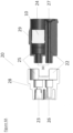
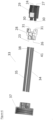
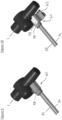
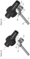
- An example of this embodiment is illustrated in Figures 9 to 18 .
- the housing section of the proximal part comprises a base section and a lid section hingedly mounted to the base section and adjustable from an open configuration to allow insertion of the distal part into the housing section and a closed configuration in which the distal part is enclosed within the housing section.
- the base section may be dimensioned to allow all, substantially all, or part of the distal part of the housing nest within the base when the lid is open.
- the lid section comprises a clamp configured to clamp the proximal part of the housing to the air port or water port of the medical instrument when the lid section is in the closed configuration.
- the clamp may be a C-shaped element configured to snap fit to the air or water port.
- the lid section comprises a clamp configured to clamp the proximal part of the housing to the air port of the medical instrument when the lid section is in the closed configuration.
- the distal opening of the second through lumen is recessed proximally relative to the distal opening of the first through lumen.
- the connector consists essentially of a proximal part comprising the housing section and the lid section, a distal part, and a non-return valve.
- the distal part and non-return valve are disposed and detached and discarded after every use, and the proximal part may be re-used and only replaced after a defined period of use, for example 24 hours.
- the invention also provides an air and water tube assembly comprising:
- the distal ends of the air and water tubes are non-detachably attached to the connector (e.g. glued).
- the assembly comprises a bottle cap non-detachably connected to a proximal part of the water tube and air tube to fluidically connect a bottle with the air and water tubes when the cap is attached to the bottle.
- the cap generally includes bores for receipt of the distal part of the water tune and air tube.
- the water tube is fixed to the cap such that a distal part of the tube extends beyond the cap (allowing the tube project into the bottle and into the water in the bottle when the cap is fitted to the bottle).
- the water tube has a bore that is smaller than a bore of the second tube.
- the invention also provides a kit of parts comprising an assembly of the invention, and additionally including one or more replacement distal parts of the connector configured for detachable attachment to the proximal part of the connector.
- the medical device is an endoscope of the type having adjacent air and water ports on the handle of the endoscope.
- the endoscope is an Olympus 025 endoscope.
- Other endoscopes suitable for use with the connector, assembly and methods of the invention include the Fuji 088, Fuji 090 and Pentax 072/076 endoscopes.
- An additional and related aspect of the invention is an adapter for a connector of an air and water tube assembly, that allows connectors of conventional air and water tube assemblies (e.g. as shown in Figures 1 and 2 ) connect with an air and water port of a medical instrument such as a scoping device (e.g. an endoscope or the like) while allowing re-use of the air and water assembly with multiple patients.
- the adapter comprises a housing having:
- the air and water port sockets of the distal end of the adapter are configured to fluidically connect with air and water ports of an endoscope, typically an Olympus 025, Fuji 088, Fuji 090 or Pentax 072/076 endoscopes.
- an endoscope typically an Olympus 025, Fuji 088, Fuji 090 or Pentax 072/076 endoscopes.
- the term “comprise,” or variations thereof such as “comprises” or “comprising,” are to be read to indicate the inclusion of any recited integer (e.g. a feature, element, characteristic, property, method/process step or limitation) or group of integers (e.g. features, element, characteristics, properties, method/process steps or limitations) but not the exclusion of any other integer or group of integers.
- the term “comprising” is inclusive or openended and does not exclude additional, unrecited integers or method/process steps.
- the connector 20 comprises a housing 21 having a first through lumen 22 for air having a proximal opening 23 and a distal opening 24, and a second through lumen 25 for water having a proximal opening 26 and a distal opening 27.
- the housing 21 has a proximal part 28 comprising the proximal openings 23, 26 configured for detachable engagement with a distal part 29 comprising the distal openings 24, 27.
- the second through lumen 25 has a non-return valve 10 disposed in the distal part of the housing that in use prevents back-flow of water from the endoscope to the water bottle and tubing.
- a proximal end of the distal part 29 of the housing has projecting outlet ports 30 configured for friction fit engagement with corresponding sockets 31 disposed on a distal end of the proximal part 28 of the housing, to fluidically couple the distal part 29 and proximal part 28 together.
- an air and water assembly comprising a two-part connector 20, air tube 34, water tube 35, and bottle cap 37.
- the bottle cap 37 is shown attached to a water bottle 36.
- the air tube 33 has a distal end 38 fluidically connected to the first through lumen 21 of the connector 20 and a proximal end 39 connected to a through hole 40 in the bottle cap 37 for fluidic connection with the bottle 36.
- the water tube 35 has a distal end 41 fluidically connected to the second through lumen 25 of the connector 20 and a proximal end 42 connected to a through hole 43 in the bottle cap 37 for fluidic connection with the water bottle 36 for pressurising the bottle.
- the proximal end 42 of the water tube 35 extends into the bottle to that an inlet of the water tube is under the level of the water in the bottle during use. It will be appreciated that the air and water tubes illustrated are quite short but in practice they will be much longer.
- Figure 5 also shown the handle 1 of an endoscope with air port 3 and water port 2.
- Figure 7 shows the air and water ports 3, 2 in more detail.
- the air and water assembly 33 is used to couple the air and water ports 3, 2 of the endoscope handle 1 with a water bottle 36.
- the bottle 36 is filled with water and the bottle cap 37 is then attached to the bottle to seal the bottle.
- pressurised air is provided to the endoscope from an external pump, and upon actuation the pressurised air may be diverted to the water bottle through the connector 20 and air tube 34 to pressurise the bottle.
- water in the bottle is forced into the endoscope through the water tube 35 and connector 20 where the water is routed by internal tubing a distal end of the endoscope for the purpose of cleaning the lens.
- the flow of water can be stopped by diverting the flow of pressurised air to the bottle through the air tube 34.
- any backflow (reflux) of water into the tubing and bottle is prevented by the non-return valve in the distal part of the connector, ensuring that the proximal part of the connector, tubing and water bottle remain sterile.
- the distal part 29 of the connector 20 (containing the non-return valve in the second through lumen) is detached from the proximal part 28 and discarded, and a replacement distal part is attached to the proximal part.
- the connector is then attached to the air and water ports of the sterilised endoscope, and an endoscopy procedure may be carried out on the next patient without any risk of cross-contamination.
- the use of the two-part connector with a non-return valve in the water lumen of the distal part allows the bottle, water, tubing, and proximal part of the connector to be re-used numerous times during a 20-hour period, with only the distal part of the connecter being discarded after every patient.
- FIG 8 illustrates an adapter fitting according to the invention, indicated generally by the reference numeral 50, in which parts described with reference to the previous embodiments are assigned the same reference numerals.
- the adapter fitting 50 is designed to be used with an existing air and water assembly such as that illustrated in Figures 1 and 2 and is used to convert a conventional one-part connector into a modified two-part connector with a non-return valve.
- the adapter 50 comprises a housing 51 having a distal end 52 with an air port socket 53 dimensioned to mate with the air port 3 of an endoscope 1 and a water port socket 54 dimensioned to mate with the water port 2 of the endoscope.
- a proximal end 55 comprises an air port 56 and a water port 57 identical to the air and water ports of the endoscope (in this case an Olympus 025 endoscope) and configured to fluidically couple with air and water sockets of the conventional connector 8.
- the adapter comprises an air lumen 58 fluidically connecting the air port socket 53 and the air port 56 and a water lumen 59 fluidically connecting the water port socket 54 and water port 57.
- a non-return valve 10 is disposed in the water lumen 59 to prevent backflow of water through the adapter.
- the adapter 50 may be coupled to a connector of a conventional air and water tube assembly, and then attached to the air and water port of an endoscope. Upon completion of the endoscopy in a first patient, the adapter is detached from the connector and discarded, and a replacement adapter attached to the connector before use in an endoscopy procedure in a second patient.
- the adapter functions in the same way as the distal part of the two-part connector, ensuring that if any backflow of water occurs that it does not come into contact with the connector allowing the connector and downstream tubing and bottle to be re-used.
- Figures 9 to 18 illustrate a connector according to an alternative embodiment of the invention, indicated generally by the reference numeral 60, in which parts described with reference to the previous embodiments are assigned the same reference numerals.
- the proximal part 28 of the connector has a housing section 61 that is dimensioned to the distal part 29 of the connector is a nested arrangement.
- the housing section has a base section 62 and a lid section 63 hingedly mounted to the base section and adjustable from an open configuration to allow insertion of the distal part 29 into the housing section and a closed configuration in which the distal part 29 is enclosed within the housing section.
- the base section and lid section are dimensioned to receive and enclose the distal part of the connector when the lid section is closed, with a distal end of the housing section open to allow the distal part of the connector fluidically couple to the air and water ports of the endoscope.
- the distal part 29 is shaped such that the distal opening 24 of the second through lumen 25 is recessed proximally relative to the distal opening 27 of the first through lumen 22. This allows the distal opening 24 fluidically couple with a proximal end 66 the air tube 3 but also exposes a distal end 67 of the air tube when the connector is coupled to the air tube.
- an underside of the lid section 63 incorporates a clamp 64 that is configured to snap-fit around the distal end 67 of the air tube 3 when the lid is closed.
- the annular flange 69 on the air tube 3 combined with the clamp 64 serves to lock the connector to the endoscope.
Landscapes
- Health & Medical Sciences (AREA)
- Life Sciences & Earth Sciences (AREA)
- Heart & Thoracic Surgery (AREA)
- Engineering & Computer Science (AREA)
- Public Health (AREA)
- Biomedical Technology (AREA)
- Animal Behavior & Ethology (AREA)
- General Health & Medical Sciences (AREA)
- Veterinary Medicine (AREA)
- Surgery (AREA)
- Hematology (AREA)
- Anesthesiology (AREA)
- Pulmonology (AREA)
- Physics & Mathematics (AREA)
- Biophysics (AREA)
- Nuclear Medicine, Radiotherapy & Molecular Imaging (AREA)
- Optics & Photonics (AREA)
- Pathology (AREA)
- Radiology & Medical Imaging (AREA)
- Mechanical Engineering (AREA)
- Medical Informatics (AREA)
- Molecular Biology (AREA)
- Endoscopes (AREA)
Claims (18)
- Verbindungsstück (20, 60) zum Fluidverbinden eines medizinischen Instruments (1) mit einem Luftschlauch (34) und einem Wasserschlauch (35), wobei das Verbindungsstück ein Gehäuse (21) umfasst, das Folgendes aufweist:ein erstes durchgehendes Lumen (22) mit einer proximalen Öffnung (26), die so ausgelegt ist, dass sie sich an den Luftschlauch (34) anschließen lässt, und einer distalen Öffnung (27), die so ausgelegt ist, dass sie sich an einen Luftanschluss (3) des medizinischen Instruments anschließen lässt, undein zweites durchgehendes Lumen (25) mit einer proximalen Öffnung (23), die so ausgelegt ist, dass sie sich an einen Wasserschlauch (35) anschließen lässt, und einer distalen Öffnung (24), die so ausgelegt ist, dass sie sich an einen Wasseranschluss (2) des medizinischen Instruments anschließen lässt,dadurch gekennzeichnet, dass es sich bei dem Verbindungsstück um ein zweiteiliges Verbindungsstück handelt, das einen proximalen Teil (28) mit den proximalen Öffnungen (26, 23) und einen distalen Teil (29) mit den distalen Öffnungen (24, 27) umfasst, wobei der proximale und der distale Teil für eine lösbare formschlüssige Verbindung ausgelegt sind und das zweite durchgehende Lumen (25) ein Rückschlagventil (10) umfasst, das in dem distalen Teil des Gehäuses angeordnet ist.
- Verbindungsstück (20, 60) nach Anspruch 1, bei dem die distalen Öffnungen (24, 27) so ausgelegt sind, dass sie sich mit Luft- und Wasseranschluss (3, 2) eines Sondiergeräts fluidverbinden lassen.
- Verbindungsstück (20, 60) nach Anspruch 1, bei dem die distalen Öffnungen (24, 27) so ausgelegt sind, dass sie sich mit einem Luft-Wasser-(LW)-Anschluss (3, 2) eines Endoskops fluidverbinden lassen.
- Verbindungsstück (20, 60) nach einem der vorhergehenden Ansprüche, bei dem jede proximale Öffnung (23, 26) eine ausgesparte Buchse umfasst, die so bemessen ist, dass sie ein Ende eines Luft- oder Wasserschlauchs (34, 35) aufnehmen kann.
- Verbindungsstück (20, 60) nach Anspruch 4, bei dem die ausgesparte Buchse (26) des ersten durchgehenden Lumens einen größeren Durchmesser aufweist als die ausgesparte Buchse (23) des zweiten durchgehenden Lumens.
- Verbindungsstück (20, 60) nach einem der vorhergehenden Ansprüche, bei dem der proximale Teil (28) und der distale Teil (29) für eine lösbare reibschlüssige Verbindung ausgelegt sind.
- Verbindungsstück (20, 60) nach einem der vorhergehenden Ansprüche, bei dem ein proximales Ende des distalen Teils (29) des Gehäuses (31) vorstehende Anschlüsse (30) umfasst und ein distales Ende des proximalen Teils (28) des Gehäuses ausgesparte Anschlüsse (31) umfasst, die so ausgelegt sind, dass sie die vorstehenden Anschlüsse aufnehmen können und so den distalen und den proximalen Teil des Gehäuses fluidkoppeln.
- Verbindungsstück (60) nach einem der vorhergehenden Ansprüche, bei dem der proximale Teil (28) einen Gehäuseabschnitt (61) umfasst, der so bemessen ist, dass er den distalen Teil (29) aufnehmen kann.
- Verbindungsstück (60) nach Anspruch 8, bei dem der Gehäuseabschnitt (61) des proximalen Teils (28) einen Grundabschnitt (62) umfasst und einen Deckelabschnitt (63), der an den Grundabschnitt angelenkt und aus einer offenen Anordnung, die ein Einführen des distalen Teils (29) in den Gehäuseabschnitt ermöglicht, und einer geschlossenen Anordnung, in der der distale Teil (29) von dem Gehäuseabschnitt umschlossen ist, verstellbar ist.
- Verbindungsstück (60) nach Anspruch 9, bei dem der Deckelabschnitt (63) eine Klemme (64) umfasst, die so ausgelegt ist, dass sie den proximalen Teil (28) des Gehäuses (21) an dem Luftanschluss (3) oder dem Wasseranschluss (2) des medizinischen Instruments (1) festklemmt, wenn sich der Deckelabschnitt in der geschlossenen Anordnung befindet.
- Verbindungsstück (60) nach Anspruch 9, bei dem der Deckelabschnitt (63) eine Klemme (64) umfasst, die so ausgelegt ist, dass sie den proximalen Teil (28) des Gehäuses (21) an dem Luftanschluss (3) des medizinischen Instruments (1) festklemmt, wenn sich der Deckelabschnitt in der geschlossenen Anordnung befindet.
- Verbindungsstück (60) nach Anspruch 11, bei dem die distale Öffnung (24) des zweiten durchgehenden Lumens (25) in Bezug auf die distale Öffnung (27) des ersten durchgehenden Lumens (22) proximal ausgespart ist.
- Luft- und Wasserschlauchbaugruppe (33), die Folgendes umfasst:ein Verbindungsstück (20, 60) nach einem der vorhergehenden Ansprüche,einen Wasserschlauch (35) mit einem distalen Ende, das über die proximale Öffnung (23) mit dem zweiten durchgehenden Lumen (25) fluidgekoppelt ist, undeinen Luftschlauch (34) mit einem distalen Ende, das über die proximale Öffnung (26) mit dem ersten durchgehenden Lumen (25) fluidgekoppelt ist.
- Baugruppe nach Anspruch 13, bei der die distalen Enden des Luft- und des Wasserschlauchs nicht lösbar an dem Verbindungsstück (20, 60) befestigt sind.
- Baugruppe nach Anspruch 13 oder 14, die eine Flasche (36) umfasst und eine Flaschenkappe (37), die nicht lösbar mit einem proximalen Teil des Wasserschlauchs (35) und des Luftschlauchs (34) verbunden ist und die Flasche so mit dem Luft-und dem Wasserschlauch fluidverbindet, wenn die Kappe an der Flasche befestigt ist.
- Baugruppe nach einem der Ansprüche 13 bis 15, bei der der Wasserschlauch (35) eine Bohrung aufweist, die kleiner ist als eine Bohrung des zweiten Schlauchs.
- Bausatz aus Teilen mit einer Baugruppe (33) nach einem der Ansprüche 13 bis 16, der zusätzlich ein oder mehrere distale Ersatzteile (29) für das Verbindungsstück (20) aufweist, die für ein lösbares Befestigen an dem proximalen Teil (28) des Verbindungsstücks ausgelegt sind.
- Adapter (50) für ein Verbindungsstück (8) von dem Typ, der eine Luft- und Wasserschlauchbaugruppe mit einem Luft- und Wasseranschluss (3, 2) eines medizinischen Instruments wie eines Sondiergeräts (1) fluidverbindet, wobei der Adapter ein Gehäuse (51) umfasst, das Folgendes aufweist:ein distales Ende (52) mit einer Luftanschlussbuchse (53), die so bemessen ist, dass sie zu dem Luftanschluss (3) des medizinischen Instruments (1) passt, und einer Wasseranschlussbuchse (54), die so bemessen ist, dass sie zu dem Wasseranschluss (2) des medizinischen Instruments passt,ein proximales Ende (55) mit einem Luftanschluss (56) und einem Wasseranschluss (57) mit der gleichen Anordnung wie der Luft- und der Wasseranschluss (3, 2) des medizinischen Instruments (1),ein Luftlumen, das die Luftanschlussbuchse (53) und den Luftanschluss (56) fluidverbindet, ein Wasserlumen, das die Wasseranschlussbuchse (54) und den Wasseranschluss (57) fluidverbindet, undein Rückschlagventil (10), das in dem Wasserlumen angeordnet ist.
Applications Claiming Priority (2)
| Application Number | Priority Date | Filing Date | Title |
|---|---|---|---|
| EP20202925 | 2020-10-20 | ||
| PCT/EP2021/079142 WO2022084418A1 (en) | 2020-10-20 | 2021-10-20 | A connector to fluidically connect a medical device with air and water tubes |
Publications (3)
| Publication Number | Publication Date |
|---|---|
| EP4231891A1 EP4231891A1 (de) | 2023-08-30 |
| EP4231891B1 true EP4231891B1 (de) | 2024-12-25 |
| EP4231891C0 EP4231891C0 (de) | 2024-12-25 |
Family
ID=73005331
Family Applications (1)
| Application Number | Title | Priority Date | Filing Date |
|---|---|---|---|
| EP21801845.5A Active EP4231891B1 (de) | 2020-10-20 | 2021-10-20 | Verbinder zum fluidischen verbinden einer medizinischen vorrichtung mit luft- und wasserrohren |
Country Status (7)
| Country | Link |
|---|---|
| US (1) | US20230381485A1 (de) |
| EP (1) | EP4231891B1 (de) |
| CN (1) | CN116322466B (de) |
| AU (1) | AU2021366293A1 (de) |
| ES (1) | ES3009988T3 (de) |
| PL (1) | PL4231891T3 (de) |
| WO (1) | WO2022084418A1 (de) |
Family Cites Families (8)
| Publication number | Priority date | Publication date | Assignee | Title |
|---|---|---|---|---|
| US5133336A (en) * | 1990-10-22 | 1992-07-28 | Endoscopy Support Services, Inc. | Disposable liquid supply system for use in an endoscope |
| JP2009521297A (ja) * | 2005-12-27 | 2009-06-04 | ストライカー ジーアイ リミテッド | 圧力解放機構を備えた内視鏡装置 |
| CN201154106Y (zh) * | 2007-12-27 | 2008-11-26 | 王华林 | 一次性压力转换器 |
| AU2011314333B2 (en) | 2010-10-14 | 2016-01-07 | Medivators, Inc. | A universal cap |
| US10456014B2 (en) * | 2012-03-30 | 2019-10-29 | United States Endoscopy Group, Inc. | Water bottle cap assemblies for an endoscopic device |
| CN203634117U (zh) * | 2013-12-26 | 2014-06-11 | 深圳市开立科技有限公司 | 一种可方便拆卸的内窥镜水气装置及其内窥镜设备 |
| US10524636B2 (en) * | 2015-02-23 | 2020-01-07 | Uroviu Corp. | Handheld surgical endoscope |
| CN110575126A (zh) * | 2019-09-24 | 2019-12-17 | 重庆市璧山区人民医院 | 一种减少交叉污染的胃肠内镜附件 |
-
2021
- 2021-10-20 PL PL21801845.5T patent/PL4231891T3/pl unknown
- 2021-10-20 WO PCT/EP2021/079142 patent/WO2022084418A1/en not_active Ceased
- 2021-10-20 CN CN202180071602.4A patent/CN116322466B/zh active Active
- 2021-10-20 ES ES21801845T patent/ES3009988T3/es active Active
- 2021-10-20 AU AU2021366293A patent/AU2021366293A1/en active Pending
- 2021-10-20 US US18/249,691 patent/US20230381485A1/en active Pending
- 2021-10-20 EP EP21801845.5A patent/EP4231891B1/de active Active
Also Published As
| Publication number | Publication date |
|---|---|
| CN116322466B (zh) | 2025-09-02 |
| AU2021366293A9 (en) | 2024-10-10 |
| ES3009988T3 (en) | 2025-03-31 |
| AU2021366293A1 (en) | 2023-06-22 |
| PL4231891T3 (pl) | 2025-06-09 |
| EP4231891A1 (de) | 2023-08-30 |
| US20230381485A1 (en) | 2023-11-30 |
| CN116322466A (zh) | 2023-06-23 |
| WO2022084418A1 (en) | 2022-04-28 |
| EP4231891C0 (de) | 2024-12-25 |
Similar Documents
| Publication | Publication Date | Title |
|---|---|---|
| US5133336A (en) | Disposable liquid supply system for use in an endoscope | |
| US6340344B1 (en) | Endoscope with a removable suction tube | |
| US9907454B2 (en) | Gas water bottle adaptor | |
| US8454498B2 (en) | In-line gas adaptor for endoscopic apparatus | |
| US20200054197A1 (en) | Water bottle cap assemblies for an endoscopic device | |
| EP0162100A1 (de) | Endoskopische anordnung mit griff und katheter | |
| US20230371793A1 (en) | Quick connect sub-assemblies for scopes | |
| EP3435834B1 (de) | Wasserflaschenkappenanordnungen für eine endoskopische vorrichtung | |
| EP4231891B1 (de) | Verbinder zum fluidischen verbinden einer medizinischen vorrichtung mit luft- und wasserrohren | |
| US20060116551A1 (en) | Single-use system and method for endoscopy pre-cleaning | |
| CN120614998A (zh) | 免消毒膀胱软镜、可重复泌尿软镜套件和一次性软镜外壳 | |
| EP4566511A1 (de) | Verbinder für ein untergeordnetes wasserzufuhrmundstück eines endoskops | |
| JP2025531285A (ja) | 内視鏡システム用のハイブリッド連結機構 | |
| CN119157445A (zh) | 一种内窥镜的可更换结构、内窥镜及内窥镜系统 | |
| CN121606243A (zh) | 一种一次性内窥镜鞘套组件 |
Legal Events
| Date | Code | Title | Description |
|---|---|---|---|
| STAA | Information on the status of an ep patent application or granted ep patent |
Free format text: STATUS: UNKNOWN |
|
| STAA | Information on the status of an ep patent application or granted ep patent |
Free format text: STATUS: THE INTERNATIONAL PUBLICATION HAS BEEN MADE |
|
| PUAI | Public reference made under article 153(3) epc to a published international application that has entered the european phase |
Free format text: ORIGINAL CODE: 0009012 |
|
| STAA | Information on the status of an ep patent application or granted ep patent |
Free format text: STATUS: REQUEST FOR EXAMINATION WAS MADE |
|
| 17P | Request for examination filed |
Effective date: 20230509 |
|
| AK | Designated contracting states |
Kind code of ref document: A1 Designated state(s): AL AT BE BG CH CY CZ DE DK EE ES FI FR GB GR HR HU IE IS IT LI LT LU LV MC MK MT NL NO PL PT RO RS SE SI SK SM TR |
|
| DAV | Request for validation of the european patent (deleted) | ||
| DAX | Request for extension of the european patent (deleted) | ||
| GRAP | Despatch of communication of intention to grant a patent |
Free format text: ORIGINAL CODE: EPIDOSNIGR1 |
|
| STAA | Information on the status of an ep patent application or granted ep patent |
Free format text: STATUS: GRANT OF PATENT IS INTENDED |
|
| INTG | Intention to grant announced |
Effective date: 20240624 |
|
| RAP3 | Party data changed (applicant data changed or rights of an application transferred) |
Owner name: GA HEALTH MEDICAL DEVICES LIMITED |
|
| GRAS | Grant fee paid |
Free format text: ORIGINAL CODE: EPIDOSNIGR3 |
|
| GRAA | (expected) grant |
Free format text: ORIGINAL CODE: 0009210 |
|
| STAA | Information on the status of an ep patent application or granted ep patent |
Free format text: STATUS: THE PATENT HAS BEEN GRANTED |
|
| AK | Designated contracting states |
Kind code of ref document: B1 Designated state(s): AL AT BE BG CH CY CZ DE DK EE ES FI FR GB GR HR HU IE IS IT LI LT LU LV MC MK MT NL NO PL PT RO RS SE SI SK SM TR |
|
| REG | Reference to a national code |
Ref country code: GB Ref legal event code: FG4D |
|
| REG | Reference to a national code |
Ref country code: CH Ref legal event code: EP |
|
| REG | Reference to a national code |
Ref country code: DE Ref legal event code: R096 Ref document number: 602021023979 Country of ref document: DE |
|
| REG | Reference to a national code |
Ref country code: IE Ref legal event code: FG4D |
|
| U01 | Request for unitary effect filed |
Effective date: 20250123 |
|
| U07 | Unitary effect registered |
Designated state(s): AT BE BG DE DK EE FI FR IT LT LU LV MT NL PT RO SE SI Effective date: 20250218 |
|
| REG | Reference to a national code |
Ref country code: ES Ref legal event code: FG2A Ref document number: 3009988 Country of ref document: ES Kind code of ref document: T3 Effective date: 20250331 |
|
| PG25 | Lapsed in a contracting state [announced via postgrant information from national office to epo] |
Ref country code: HR Free format text: LAPSE BECAUSE OF FAILURE TO SUBMIT A TRANSLATION OF THE DESCRIPTION OR TO PAY THE FEE WITHIN THE PRESCRIBED TIME-LIMIT Effective date: 20241225 |
|
| PG25 | Lapsed in a contracting state [announced via postgrant information from national office to epo] |
Ref country code: NO Free format text: LAPSE BECAUSE OF FAILURE TO SUBMIT A TRANSLATION OF THE DESCRIPTION OR TO PAY THE FEE WITHIN THE PRESCRIBED TIME-LIMIT Effective date: 20250325 |
|
| PG25 | Lapsed in a contracting state [announced via postgrant information from national office to epo] |
Ref country code: GR Free format text: LAPSE BECAUSE OF FAILURE TO SUBMIT A TRANSLATION OF THE DESCRIPTION OR TO PAY THE FEE WITHIN THE PRESCRIBED TIME-LIMIT Effective date: 20250326 |
|
| PG25 | Lapsed in a contracting state [announced via postgrant information from national office to epo] |
Ref country code: RS Free format text: LAPSE BECAUSE OF FAILURE TO SUBMIT A TRANSLATION OF THE DESCRIPTION OR TO PAY THE FEE WITHIN THE PRESCRIBED TIME-LIMIT Effective date: 20250325 |
|
| PG25 | Lapsed in a contracting state [announced via postgrant information from national office to epo] |
Ref country code: SM Free format text: LAPSE BECAUSE OF FAILURE TO SUBMIT A TRANSLATION OF THE DESCRIPTION OR TO PAY THE FEE WITHIN THE PRESCRIBED TIME-LIMIT Effective date: 20241225 |
|
| PG25 | Lapsed in a contracting state [announced via postgrant information from national office to epo] |
Ref country code: IS Free format text: LAPSE BECAUSE OF FAILURE TO SUBMIT A TRANSLATION OF THE DESCRIPTION OR TO PAY THE FEE WITHIN THE PRESCRIBED TIME-LIMIT Effective date: 20250425 |
|
| PG25 | Lapsed in a contracting state [announced via postgrant information from national office to epo] |
Ref country code: SK Free format text: LAPSE BECAUSE OF FAILURE TO SUBMIT A TRANSLATION OF THE DESCRIPTION OR TO PAY THE FEE WITHIN THE PRESCRIBED TIME-LIMIT Effective date: 20241225 |
|
| PG25 | Lapsed in a contracting state [announced via postgrant information from national office to epo] |
Ref country code: CZ Free format text: LAPSE BECAUSE OF FAILURE TO SUBMIT A TRANSLATION OF THE DESCRIPTION OR TO PAY THE FEE WITHIN THE PRESCRIBED TIME-LIMIT Effective date: 20241225 |
|
| PLBE | No opposition filed within time limit |
Free format text: ORIGINAL CODE: 0009261 |
|
| STAA | Information on the status of an ep patent application or granted ep patent |
Free format text: STATUS: NO OPPOSITION FILED WITHIN TIME LIMIT |
|
| 26N | No opposition filed |
Effective date: 20250926 |
|
| U20 | Renewal fee for the european patent with unitary effect paid |
Year of fee payment: 5 Effective date: 20251030 |
|
| PGFP | Annual fee paid to national office [announced via postgrant information from national office to epo] |
Ref country code: GB Payment date: 20251010 Year of fee payment: 5 |
|
| PGFP | Annual fee paid to national office [announced via postgrant information from national office to epo] |
Ref country code: IE Payment date: 20251015 Year of fee payment: 5 |
|
| PGFP | Annual fee paid to national office [announced via postgrant information from national office to epo] |
Ref country code: PL Payment date: 20251014 Year of fee payment: 5 |
|
| PGFP | Annual fee paid to national office [announced via postgrant information from national office to epo] |
Ref country code: ES Payment date: 20251118 Year of fee payment: 5 |