EP3533306A1 - Vorrichtung für dienstverbindungen von traktor-anhänger-kombinationen - Google Patents
Vorrichtung für dienstverbindungen von traktor-anhänger-kombinationen Download PDFInfo
- Publication number
- EP3533306A1 EP3533306A1 EP17182458.4A EP17182458A EP3533306A1 EP 3533306 A1 EP3533306 A1 EP 3533306A1 EP 17182458 A EP17182458 A EP 17182458A EP 3533306 A1 EP3533306 A1 EP 3533306A1
- Authority
- EP
- European Patent Office
- Prior art keywords
- arm
- equipment
- services
- trailer
- tractor
- Prior art date
- Legal status (The legal status is an assumption and is not a legal conclusion. Google has not performed a legal analysis and makes no representation as to the accuracy of the status listed.)
- Withdrawn
Links
Images


Classifications
-
- B—PERFORMING OPERATIONS; TRANSPORTING
- B60—VEHICLES IN GENERAL
- B60D—VEHICLE CONNECTIONS
- B60D1/00—Traction couplings; Hitches; Draw-gear; Towing devices
- B60D1/58—Auxiliary devices
- B60D1/62—Auxiliary devices involving supply lines, electric circuits, or the like
- B60D1/64—Couplings or joints therefor
-
- A—HUMAN NECESSITIES
- A01—AGRICULTURE; FORESTRY; ANIMAL HUSBANDRY; HUNTING; TRAPPING; FISHING
- A01B—SOIL WORKING IN AGRICULTURE OR FORESTRY; PARTS, DETAILS, OR ACCESSORIES OF AGRICULTURAL MACHINES OR IMPLEMENTS, IN GENERAL
- A01B59/00—Devices specially adapted for connection between animals or tractors and agricultural machines or implements
- A01B59/002—Details, component parts
Definitions
- This invention relates to equipment for services interconnection of tractor-trailer combinations.
- Equipment of this nature is conventionally mounted on the front of the trailer for use in establishing services interconnection between the tractor and trailer when the trailer is coupled to the tractor.
- the services interconnection is established to the interconnection equipment on the front of the trailer via individual electrical, pneumatic-hose and other flexible connector lines that extend (normally in extendable-coil form) from the back of the driver's cab or other location of the tractor to be plugged into sockets or otherwise connected to the interconection equipment when the tractor and trailer are coupled together.
- the sockets and other connectors of the interconnection equipment are mounted on a moveable services-connector plate.
- the plate is retained in a central, 'normal' or 'running' location when the tractor-trailer is moving or is parked, but is moveable laterally from this location across the front of the trailer into an 'extended', or 'deployed' location to one side of the trailer whenever connections to it are to be established or otherwise changed.
- the services-connector plate may be mounted on an arm or other member which is slidable or otherwise moveable relative to the mounting of the equipment to locate the plate outwardly, and desirably downwardly, beyond the side of the tractor-trailer combination at a height and distance that enables the driver or other person comfortable and ready-access to the connector-plate while standing on the ground alongside the tractor-trailer combination.
- equipment for services interconnection of a tractor-trailer combination wherein a moveable connector-plate or other member of the services interconnection is restrained in a defined location from movement relative to its mounting during movement and manoeuvring of the tractor-trailer combination, by at least projection-within-socket engagement in the defined location between the connector-plate or other member and the mounting.
- the projection-within-socket engagement may be between one or projecting elements of the connector-plate or other member of the services-interconnection equipment, and respective sockets of the mounting.
- the projection-within-socket engagement may be between one or more sockets of the mounting, and respective projecting elements of the moveable connector-plate or other member of the services-interconnection equipment.
- the one or more projecting elements may be pins, and the sockets may be respective holes or slots to receive the projecting elements.
- each projecting element or pin may have a conical or otherwise-shaped leading end to facilitate entry and alignment of it with the relevant socket, hole or slot, as the moveable connector-plate moves into the defined location.
- Each conical pin serves individually to restrain movement in four lateral planes (upwards, downwards, forwards and backwards), whereas two pins spaced apart, or a single flat plate to engage in a slot, can be used to restrain rotational as well as other movements.
- the defined location may be specifically that in which the connector-plate or other member of the services interconnection is retained in its 'normal' or 'running' location when the tractor-trailer is moving or is parked. But restraint may be provided at least in part, similarly by means of pins or other projecting elements or one or more flat plates in other locations, for example when the connector-plate or other member of the services interconnection is 'extended', or 'deployed', or is in some intermediate location between the 'normal' or 'running' location and the 'extended' or 'deployed' location.
- forces on the moveable services-connector-plate or other member may be at least partly restrained while the moveable plate or other member is in its 'normal' or 'retracted' location, by projection-within-socket engagement that occurs in that location between the moveable services-connector plate or other member and part of the mounting of the services-interconnection equipment.
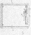
- Figures 1 to 3 are, respectively, simplified representations in perspective view, plan view and front elevation of extendable interconnection equipment according to the present invention for mounting on the front of a trailer of a tractor-trailer combination, to enable manual connection and disconnection of services to and from the trailer via individual connection lines (not shown), the equipment being shown in the non-extended or retracted condition it normally occupies when the tractor-trailer is parked, manoeuvring or in motion.
- Figures 4a and 4c represent (to a larger scale) details of the interconnection equipment at opposite leading and trailing ends respectively of locations that are graphically encircled in Figure 2
- Figures 5 to 7 are simplified representations respectively in perspective view, plan view and front elevation of the interconnection equipment of Figures 1 to 3 , when the equipment is in its 'deployed' or extended condition from its 'normal' condition;
- Figures 8a to 8c represent (to the enlarged scale) details of the interconnection equipment at respective locations that are graphically encircled in Figures 5 and 6 ;
- Figure 9 is illustrative of part of an implementation of equipment according to the invention for services interconnection of a tractor-trailer combination
- Figure 10 is a view of equipment according to the invention for mounting on the front of a trailer
- Figure 11 is illustrative of the equipment of Figure 10 mounted on the front of a trailer of a tractor-trailer combination to extend laterally of the trailer, the equipment being shown in its 'normal' or 'running' condition;
- Figure 12 is a view corresponding to Figure 11 with the extendable equipment shown in its 'deployed' or 'extended' condition;
- Figures 13 and 14 are illustrative of the use of plates engaged within slots to provide restraint and stability to the moving arm of interconnection equipment in accordance with the present invention.
- the interconnection equipment 1 in this simplified example involves an elongate arm 2 that is mounted for sliding back and forth on bearings 3 along a guide 4 that extends horizontally widthwise of the front of the trailer.
- the arm 2 has brackets 5 and 6 at its leading and trailing ends respectively, and a bracket 7 at an intermediate location of its length for meeting in pairs face-to-face with brackets 8 and 9 at the two ends of the guide 4, in dependence upon whether the arm 2 is in its 'normal', unextended condition as shown in Figures 1 to 3 , or in its 'extended' condition as shown in Figures 5 to 7 .
- the bracket 5 at the leading end carries sockets and other connectors (not shown) by which services connections from the tractor are made to the trailer.
- the pair of brackets 5 and 8 are paired together face-to-face at the leading end of the arm 2, whereas the pair of brackets 6 and 9 are paired together face-to-face at the trailing end of the arm 2.
- the pair of brackets 7 and 8 are paired together face-to-face at the intermediate locations of the arm 2 and guide 4.
- two pins 10 of one of the brackets engage in respective sockets 11 illustrated in Figure 8a ) of the other bracket.
- each pin 10 has a conical leading end 12 (as illustrated in Figures 4a and 4b and Figures 8b and 8c ) so as more-readily to locate and engage fully (as illustrated in Figures 8b and 8c ) in the relevant socket as the paired brackets close onto one another face-to-face; each socket may be a circular hole as illustrated by the holes 11 of Figure 8a , or a slot.
- FIG 9 is illustrative of a situation with practical interconnection equipment where an arm 22 moving along a support beam 24.
- the beam 24 holds bearings (not shown) which guide the movement of the arm 22, and carries a bolted-on bracket 26 that is closing face-to-face onto a bracket 29 at the trailing end of the beam 24 in returning to the unextended condition of the interconnection equipment.
- This is just prior to engagement of a pair of pins 30 with respective holes 31 (only one shown) in the bracket 26.
- the conical tips 32 of the pins 30 enter the holes 31 and effect any slight adjustment to the alignment of the arm 22 required to ensure that as the movement is completed the pins 30 fully and closely engage in the holes 31.
- this pin-socket engagement establishes for the arm 22 an advantageous force-restraining protection and stability against vibration and shock, so that these forces are not transmitted to the supporting bearings.
- equipment 40 in accordance with the invention is for mounting, as illustrated by Figure 11 , on the front 41 of a trailer 42.
- the equipment 40 as indicated more clearly in Figure 10 , has an arm 45 that carries a connector plate 46 which is provided with electrical sockets 47 and pneumatic-hose connectors 48 for intercoupling with appropriate service-connection lines (not shown) from the tractor (not shown).
- Pin-in-socket engagement (not shown) between for example the arm 45 and a fixed rail 49 is provided in the equipment to restrain the arm 45 from vibration and twisting under forces created with movement of the trailer in normal use.
- the arm 45 has a pivot 50 at its distal end with a slider 51.
- the slider 51 slides along an elongate guide 52 as a handle 53 on the connector plate 46 is pulled laterally across the front 41 of the trailer in extending the arm 45 widthwise of the trailer and taking the plate 46 progressively to the side of the trailer 42. Further pulling of the handle 53 brings the slider 51 to the proximal end of the guide 52 and clearing it under the rail 49 of the mounting structure of the equipment.
- This allows the arm 45 to pivot down on the pivot 50 into its fully extended or deployed condition as shown in Figure 12
- the connector-plate 46 is clear of the side of the trailer and at a convenient height to allows the driver or other person standing on the ground to connect or disconnect the service lines with the sockets 47 and 48 on the plate 46.
- connection and disconnection of the services lines results in forces tending to push the arm 45 upwards and downwards and to twist it in both senses.
- Pin-in-socket engagement (not shown) between for example the arm 45, the fixed rail 49 and a fixed rail 54, is provided in the equipment to restrain the arm 45 from the upward/downward forces and twisting in this condition.
- Latches with manually releasable latching arms are provided to hold the arm 45 locked in position in the retracted or normal condition, and in its deployed or extended condition.
- a manually-releasable lock with lever arm 56 is effective to retain the arm 45 and the plate 46 in the extended or deployed condition.
- Figures 13 and 14 show use of plates 60 within slots 61 that may be used instead of pins within holes or slots for ensuring the advantageous restraint and stability against the transmission of vibration and shock via the connector plate 46 to the support bearings of the arm 45.
- the restraint and stability are provided between the arm 45 and the rail 49 of the equipment mounting.
Landscapes
- Engineering & Computer Science (AREA)
- Life Sciences & Earth Sciences (AREA)
- Mechanical Engineering (AREA)
- Transportation (AREA)
- Zoology (AREA)
- Soil Sciences (AREA)
- Environmental Sciences (AREA)
- Agricultural Machines (AREA)
Priority Applications (1)
| Application Number | Priority Date | Filing Date | Title |
|---|---|---|---|
| EP17182458.4A EP3533306A1 (de) | 2017-07-20 | 2017-07-20 | Vorrichtung für dienstverbindungen von traktor-anhänger-kombinationen |
Applications Claiming Priority (1)
| Application Number | Priority Date | Filing Date | Title |
|---|---|---|---|
| EP17182458.4A EP3533306A1 (de) | 2017-07-20 | 2017-07-20 | Vorrichtung für dienstverbindungen von traktor-anhänger-kombinationen |
Publications (1)
| Publication Number | Publication Date |
|---|---|
| EP3533306A1 true EP3533306A1 (de) | 2019-09-04 |
Family
ID=67432547
Family Applications (1)
| Application Number | Title | Priority Date | Filing Date |
|---|---|---|---|
| EP17182458.4A Withdrawn EP3533306A1 (de) | 2017-07-20 | 2017-07-20 | Vorrichtung für dienstverbindungen von traktor-anhänger-kombinationen |
Country Status (1)
| Country | Link |
|---|---|
| EP (1) | EP3533306A1 (de) |
Citations (7)
| Publication number | Priority date | Publication date | Assignee | Title |
|---|---|---|---|---|
| GB1499815A (en) * | 1975-03-21 | 1978-02-01 | Chrysler Uk | Electrical plug and socket assemblies |
| DE9000214U1 (de) * | 1989-01-12 | 1990-03-01 | Nicolas S.A., Champs-Sur-Yonne, Fr | |
| EP0950549A1 (de) * | 1998-04-17 | 1999-10-20 | Ellebi S.r.l. | Fahrzeugabschleppvorrichtung mit abnehmbarer Kugelkopfkupplung, selbsttätiger Vorrichtung und Stromsteckdose |
| US20050194762A1 (en) * | 2004-03-03 | 2005-09-08 | Brackett Wesley E. | Locking trailer tongue extension assembly |
| GB2441752A (en) * | 2006-09-15 | 2008-03-19 | Fontaine Int Europe Ltd | A plug in coupling arrangement for a tractor and a trailer |
| GB2467955A (en) * | 2009-02-23 | 2010-08-25 | Don Bur | Coupling connection arrangement for a cab and trailer |
| GB2507802A (en) * | 2012-11-12 | 2014-05-14 | Don Bur Bodies & Trailers Ltd | Power services coupling |
-
2017
- 2017-07-20 EP EP17182458.4A patent/EP3533306A1/de not_active Withdrawn
Patent Citations (7)
| Publication number | Priority date | Publication date | Assignee | Title |
|---|---|---|---|---|
| GB1499815A (en) * | 1975-03-21 | 1978-02-01 | Chrysler Uk | Electrical plug and socket assemblies |
| DE9000214U1 (de) * | 1989-01-12 | 1990-03-01 | Nicolas S.A., Champs-Sur-Yonne, Fr | |
| EP0950549A1 (de) * | 1998-04-17 | 1999-10-20 | Ellebi S.r.l. | Fahrzeugabschleppvorrichtung mit abnehmbarer Kugelkopfkupplung, selbsttätiger Vorrichtung und Stromsteckdose |
| US20050194762A1 (en) * | 2004-03-03 | 2005-09-08 | Brackett Wesley E. | Locking trailer tongue extension assembly |
| GB2441752A (en) * | 2006-09-15 | 2008-03-19 | Fontaine Int Europe Ltd | A plug in coupling arrangement for a tractor and a trailer |
| GB2467955A (en) * | 2009-02-23 | 2010-08-25 | Don Bur | Coupling connection arrangement for a cab and trailer |
| GB2507802A (en) * | 2012-11-12 | 2014-05-14 | Don Bur Bodies & Trailers Ltd | Power services coupling |
Similar Documents
| Publication | Publication Date | Title |
|---|---|---|
| RU2550099C2 (ru) | Автоматическая сцепная система трактора для буксируемых инструментов | |
| CN103579849B (zh) | 包括带拉片的锁闩组件的电连接器 | |
| CN104590406B (zh) | 配重组件 | |
| US9592711B2 (en) | Towing assembly with pivot joints | |
| EP1913804A1 (de) | Kupplung für einen Traktor | |
| US10946703B2 (en) | Tow bar apparatus and method | |
| CN101595597A (zh) | 天线连接器组件 | |
| EP2670055A1 (de) | Mobiltelefonintegrationssystem | |
| US20180306348A1 (en) | Cable management system for telescoping assembly | |
| DE202012102901U1 (de) | USB-Steckanschluss und USB-Steckanschlusseinheit | |
| GB2553904A (en) | Equipment for services interconnections of tractor-trailer combinations | |
| EP3533306A1 (de) | Vorrichtung für dienstverbindungen von traktor-anhänger-kombinationen | |
| US8696024B2 (en) | Coupler for a vehicle and a vehicle comprising same | |
| DE102017109488A1 (de) | An einem Heckbereich eines Kraftfahrzeugs montierbare Halteeinrichtung | |
| US20030087543A1 (en) | Apparatus and method of a locomotive easy connection multiple unit (MU) cable assembly | |
| CN106163200B (zh) | 滑轨总成 | |
| WO2013087260A1 (en) | Link holder | |
| US20100178142A1 (en) | Base structure for a truck bed extension and ramp system | |
| CA2913911A1 (en) | Towing assembly with pivot joints | |
| US20020090855A1 (en) | Easily removable and attachable mechanical/electrical coupling | |
| CN106655002B (zh) | 电力施工用镰刀 | |
| EP3740419A1 (de) | Kopplungskomponente, system zum koppeln und verfahren zur montage einer kopplungskomponente | |
| EP2657177A1 (de) | Wagen für das Abschleppen von Fahrzeugen | |
| CN104093578A (zh) | 牵引装置 | |
| AT517590A4 (de) | Flexibles Verkabelungs- und Elektrifizierungssystem für Tische |
Legal Events
| Date | Code | Title | Description |
|---|---|---|---|
| PUAI | Public reference made under article 153(3) epc to a published international application that has entered the european phase |
Free format text: ORIGINAL CODE: 0009012 |
|
| AK | Designated contracting states |
Kind code of ref document: A1 Designated state(s): AL AT BE BG CH CY CZ DE DK EE ES FI FR GB GR HR HU IE IS IT LI LT LU LV MC MK MT NL NO PL PT RO RS SE SI SK SM TR |
|
| AX | Request for extension of the european patent |
Extension state: BA ME |
|
| STAA | Information on the status of an ep patent application or granted ep patent |
Free format text: STATUS: THE APPLICATION IS DEEMED TO BE WITHDRAWN |
|
| 18D | Application deemed to be withdrawn |
Effective date: 20200305 |