EP3532184B1 - Dichter vertikaler plattenfilter - Google Patents
Dichter vertikaler plattenfilter Download PDFInfo
- Publication number
- EP3532184B1 EP3532184B1 EP17801073.2A EP17801073A EP3532184B1 EP 3532184 B1 EP3532184 B1 EP 3532184B1 EP 17801073 A EP17801073 A EP 17801073A EP 3532184 B1 EP3532184 B1 EP 3532184B1
- Authority
- EP
- European Patent Office
- Prior art keywords
- filter
- plates
- filtrate
- external
- tank
- Prior art date
- Legal status (The legal status is an assumption and is not a legal conclusion. Google has not performed a legal analysis and makes no representation as to the accuracy of the status listed.)
- Active
Links
Images


Classifications
-
- B—PERFORMING OPERATIONS; TRANSPORTING
- B01—PHYSICAL OR CHEMICAL PROCESSES OR APPARATUS IN GENERAL
- B01D—SEPARATION
- B01D29/00—Filters with filtering elements stationary during filtration, e.g. pressure or suction filters, not covered by groups B01D24/00 - B01D27/00; Filtering elements therefor
- B01D29/39—Filters with filtering elements stationary during filtration, e.g. pressure or suction filters, not covered by groups B01D24/00 - B01D27/00; Filtering elements therefor with hollow discs side by side on, or around, one or more tubes, e.g. of the leaf type
- B01D29/395—Filters with filtering elements stationary during filtration, e.g. pressure or suction filters, not covered by groups B01D24/00 - B01D27/00; Filtering elements therefor with hollow discs side by side on, or around, one or more tubes, e.g. of the leaf type mounted axially on the tube
-
- B—PERFORMING OPERATIONS; TRANSPORTING
- B01—PHYSICAL OR CHEMICAL PROCESSES OR APPARATUS IN GENERAL
- B01D—SEPARATION
- B01D29/00—Filters with filtering elements stationary during filtration, e.g. pressure or suction filters, not covered by groups B01D24/00 - B01D27/00; Filtering elements therefor
- B01D29/50—Filters with filtering elements stationary during filtration, e.g. pressure or suction filters, not covered by groups B01D24/00 - B01D27/00; Filtering elements therefor with multiple filtering elements, characterised by their mutual disposition
- B01D29/52—Filters with filtering elements stationary during filtration, e.g. pressure or suction filters, not covered by groups B01D24/00 - B01D27/00; Filtering elements therefor with multiple filtering elements, characterised by their mutual disposition in parallel connection
- B01D29/54—Filters with filtering elements stationary during filtration, e.g. pressure or suction filters, not covered by groups B01D24/00 - B01D27/00; Filtering elements therefor with multiple filtering elements, characterised by their mutual disposition in parallel connection arranged concentrically or coaxially
-
- B—PERFORMING OPERATIONS; TRANSPORTING
- B01—PHYSICAL OR CHEMICAL PROCESSES OR APPARATUS IN GENERAL
- B01D—SEPARATION
- B01D35/00—Filtering devices having features not specifically covered by groups B01D24/00 - B01D33/00, or for applications not specifically covered by groups B01D24/00 - B01D33/00; Auxiliary devices for filtration; Filter housing constructions
- B01D35/16—Cleaning-out devices, e.g. for removing the cake from the filter casing or for evacuating the last remnants of liquid
-
- B—PERFORMING OPERATIONS; TRANSPORTING
- B01—PHYSICAL OR CHEMICAL PROCESSES OR APPARATUS IN GENERAL
- B01D—SEPARATION
- B01D29/00—Filters with filtering elements stationary during filtration, e.g. pressure or suction filters, not covered by groups B01D24/00 - B01D27/00; Filtering elements therefor
- B01D29/11—Filters with filtering elements stationary during filtration, e.g. pressure or suction filters, not covered by groups B01D24/00 - B01D27/00; Filtering elements therefor with bag, cage, hose, tube, sleeve or like filtering elements
- B01D29/13—Supported filter elements
- B01D29/15—Supported filter elements arranged for inward flow filtration
-
- B—PERFORMING OPERATIONS; TRANSPORTING
- B01—PHYSICAL OR CHEMICAL PROCESSES OR APPARATUS IN GENERAL
- B01D—SEPARATION
- B01D29/00—Filters with filtering elements stationary during filtration, e.g. pressure or suction filters, not covered by groups B01D24/00 - B01D27/00; Filtering elements therefor
- B01D29/62—Regenerating the filter material in the filter
- B01D29/66—Regenerating the filter material in the filter by flushing, e.g. counter-current air-bumps
- B01D29/668—Regenerating the filter material in the filter by flushing, e.g. counter-current air-bumps with valves, e.g. rotating valves for coaxially placed filtering elements
-
- B—PERFORMING OPERATIONS; TRANSPORTING
- B01—PHYSICAL OR CHEMICAL PROCESSES OR APPARATUS IN GENERAL
- B01D—SEPARATION
- B01D29/00—Filters with filtering elements stationary during filtration, e.g. pressure or suction filters, not covered by groups B01D24/00 - B01D27/00; Filtering elements therefor
- B01D29/88—Filters with filtering elements stationary during filtration, e.g. pressure or suction filters, not covered by groups B01D24/00 - B01D27/00; Filtering elements therefor having feed or discharge devices
- B01D29/94—Filters with filtering elements stationary during filtration, e.g. pressure or suction filters, not covered by groups B01D24/00 - B01D27/00; Filtering elements therefor having feed or discharge devices for discharging the filter cake, e.g. chutes
Definitions
- the present invention relates to a pressure filter with vertical plates with improved deconstruction making it possible to bring its plates closer together, and to its deconstruction method.
- filters whose plates are arranged in a star, there are some which only include plates comprising the same number of filtering elements. These filters are called “simple star”. There are also some which comprise alternating plates with two filtering elements comprising a long pipe, called “double plates”, and plates with one filtering element comprising a short pipe, called “single plates”. The single plates are housed at the inner periphery of the tank, in the space left free by the double plates. These filters are called "double star".
- the trays are immersed in the tank containing a suspension to be filtered.
- This tank is pressurized while the plates, via their tubing, are successively put under negative pressure to filter the suspension (filtration phase), then under overpressure to detach the "cake", that is to say the solid fraction of the suspension which has accumulated on the fabric during the filtration (deconstruction phase).
- filtration phase filter the suspension
- overpressure detach the "cake" that is to say the solid fraction of the suspension which has accumulated on the fabric during the filtration (deconstruction phase).
- Blowing When the build-up is done using a counter-current fluid, it is called "blowing".
- the object of the invention is to provide a filter that is both more compact and allows continuous extraction of the filtrate and does not have the above drawbacks.
- the vertical plate filter comprises plates each comprising a pipe connected to an external collector, said filter is characterized in that it comprises at least two external collectors, that, for all the plates, two adjacent plates are connected to two different external manifolds and that each plate comprises at least one filtering element, each filtering element consisting of at least two drains and a cloth, the cloth having compartments in each of which a drain is inserted.
- each filtering element consisting of at least two drains and a cloth, the cloth having compartments in each of which a drain is inserted.
- the plates of the filter are arranged in a star.
- the filter comprises an alternation of plates with two filtering elements comprising a long pipe, called “double plates”, and plates with one filtering element comprising a short pipe, called “single plates”.
- the single plates are housed at the inner periphery of the tank, in the space left free by the double plates. This makes it possible to increase the number of trays for the filters of large dimensions and therefore the filtration capacity.
- the filter is then called "double star”.
- each single plate is connected to a double plate, thus forming pairs of plates.
- the connection of single plates and double plates makes it possible to reduce by half the number of connections to the external collectors. This optimizes the space available outside the tank.
- the short tube of a single plate is connected to the long tube of a double plate by a conduit connecting the two plates.
- each pair of plates is connected to one and only one external collector through the tubing of the double plate.
- the mouth section of the tubing of the double platter is larger than that of the single platter. It can thus, in addition to its own flow of filtrate, take up the flow of filtrate extracted from the single plate during filtration, and, in addition to its own flow of blowing fluid, take up the flow of blowing fluid intended for the single plate during dismantling.
- the double star filter comprises N external collectors, N being greater than or equal to three. It is thus possible to apply blowing alternately to N groups of plates.
- N consecutive pairs of plates are connected to the N external collectors.
- the single tray and the double tray of the same pair are spaced by an even number of trays.
- the pairs of trays connected to the same external collector thus form a group of non-adjacent trays called "independent group of trays", the trays of which can be opened simultaneously.
- the filter therefore comprises N independent groups of plates which it is possible to build up by establishing the blowing counter-current alternately in each of the N external collectors.
- the single and double plates of the same pair are spaced of two trays. This arrangement makes it possible to build, in the filter comprising three external collectors, a tray every three trays, that is to say that when a tray is removed, the two adjacent trays and those which follow them directly are not removed. .
- the invention also relates to a process for removing the cakes of a vertical plate filter having at least one of the preceding characteristics, said process is characterized in that each external collector is traversed by a current of filtrate which is reversed according to a cycle predefined, and in that the cycles of all the external collectors are identical and out of phase with each other.
- the current inversions correspond to the passages from the filtration phase to the phase of deconstruction of the plates connected to this collector, and vice versa.
- At each deconstruction phase only the plates connected to a single external collector are deconstructed, the other plates remaining in the filtration phase, thus ensuring the continuity of the extraction of the filtrate. This ensures that two adjacent trays are never destroyed at the same time.
- the filtrate current inversion cycles of all the external collectors are out of phase by the same time interval.
- the filtration phases of each independent group of plates must be out of phase by the same time interval in order to limit variations in the flow rate of filtrate extracted from the filter.
- the inversion of the filtrate current is carried out by means of a pump, through a blowing circuit which can place the discharge of said pump in communication with each of the external collectors.
- This pump sends filtrate alternately into each of the external collectors at a pressure higher than that of the filter, thus putting the corresponding plates under overpressure to carry out their deconstruction.
- the inversion of the filtrate current is carried out by means of a pressurized balloon filled with said filtrate, through a blowing circuit capable of putting the outlet of said balloon on pressurized in communication with each of the external collectors.
- This over-pressurized balloon supplied with compressed air through a differential pressure regulator, sends filtrate alternately into each of the external collectors at a pressure higher than that of the filter, thus putting the corresponding plates under overpressure to proceed with their deconstruction.
- the blowing circuit is equipped in parallel with a safety spillway, of height between 1 and 5 m above the filter, connected inside the filter in the upper part of the tank of said filter.
- This safety overflow naturally limits the blowing overpressure in order to avoid any risk of damaging the filtering elements of the plates.
- the inversion of the filtrate current is carried out by means of a balloon filled with said filtrate, loaded on the filter and connected to the tank of said filter in their upper part, said inversion being carried out through a blowing circuit capable of putting the outlet of said balloon in communication with each of the external collectors.
- This balloon subjected to the same pressure as the filter by the communication of their upper part, sends filtrate, under the sole effect of gravity, alternately in each of the external collectors at a pressure higher than that of the filter, thus putting the corresponding trays under overpressure to proceed with their dismantling.
- the inversion of the filtrate current is carried out by means of balloons filled with said filtrate, loaded on the filter and connected to the tank of said filter in their upper part, said inversion being carried out through blowing circuits which can each putting the outlet of one and only one of said balloons in communication with one and only one of the external collectors.
- These balloons subjected to the same pressure as the filter by the communication of their upper part, send filtrate, under the sole effect of gravity, alternately in each of the collectors outside at a pressure higher than that of the filter, thus putting the corresponding plates under overpressure to proceed with their deconstruction.
- the upper part of the balloons is located between 1 and 5 m above the filter.
- the blowing overpressure is thus naturally limited in order to avoid any risk of damaging the filtering elements of the plates.
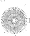
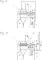
- a prior art filter 1, illustrated picture 2 Where picture 3 is a pressurized vertical 2-plate filter for the liquid/solid separation of a loaded suspension. It consists of a cylindrical tank 3 with a conical lower bottom 30 and a domed removable lid 31 shown on the figures 9 to 12 . The trays 2 are suspended vertically inside the tank 3 and arranged radially in a star.
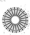
- the state-of-the-art small-diameter filters 1, illustrated picture 3 are equipped with plates 2 all identical, connected through the wall 32 of the tank 3 by bent tubes, called “filtrate outlets” 4, to an external collector 5 which goes around the filter (single star arrangement).
- the state-of-the-art large-diameter filters 1, illustrated picture 2 are equipped with plates 2 of two different types, plates 2 with one filtering element 22, called simple plates 20, and plates 2 with two filtering elements 22, called double plates 21. These simple plates 20 and these double plates 21 are connected through the wall 32 of the tank 3 by filtrate outlets 4, to an external collector 5 (double star arrangement). In this case, all the plates 2 are grouped together in pairs, a single plate 20 and a double plate 21 adjacent having a common filtrate outlet 4.
- Filter 1 of the figure 1 is a double star filter according to the invention, the vertical plates 2 of which are connected in independent groups to three separate external collectors 5 .
- a third of the single trays 20 and double trays 21 are connected to a first outer collector 50, a second third to a second outer collector 51, and the third third to the third outer collector 52.
- Each single tray 20 is connected to a double tray 21 via a conduit 23, thus forming a pair of tray.
- the double plate 21 of each pair is connected to one and only one external collector 5 by a filtrate outlet 4.
- the number N of outer collectors 5 is three.
- N being greater than or equal to three, there would be N independent groups of plates 2 each connected to one of the N external collectors 5.
- the filter therefore comprises three independent groups of plates 2.
- a first independent group of plates 2 is represented in black on the figure 4 , a second group in hatched, and the third group in white.
- a double tray 21 from the first group (black) is followed by a single tray 20 from the third group (white), then a double tray 21 from the second group (hatched), then a single tray 20 from the first group ( black), then a double 21 board from the third group (white), then a board single 20 from the second group (hatched), then a double 21 board from the first group (black) and so on.
- the single plates 20 and the double plates 21 of the same pair due to their distance, are no longer connected to each other through the wall 32 of the tank 3 as in the state of the art, but by means of a removable conduit 23 represented on the figure 4 in the color of the group of independent trays to which the conduit 23 belongs. In this arrangement, the filtering elements of the same group are never adjacent.
- the three modes of representation used highlight the different circulation circuits through the pipes 200, the conduits 23 and the filtrate outlets 4.
- the number N of external collectors 5 is three, and the single plate 20 and the double plate 21 of the same pair are spaced apart by two plates 2.
- N external collectors 5, N being greater than or equal to three the single tray 20 and the double tray 21 of the same pair will be spaced apart by two or another even number of trays 2.
- all the single plates 20 and all the double plates 21 respectively comprise one and two filtering elements 22 each consisting of drains 220 and a cloth 221. These filtering elements 22 are connected to the pipes 200 of the plates 2. Each conduit 23 connection connects said pipes 200 of the pairs of plates 2 by forming a bridge between them. Gaskets 230, placed between the pipes 200 and each of the two ends of the ducts 23 are compressed by wire springs 231 which exert sufficient force to guarantee sealing.
- the filter elements 22 comprise several drains 220, each drain being arranged in a compartment 222 made in the fabric 221. These compartments 222 can be made with, for example, seams or welds 223 on said fabric 221.
- filter elements 22 are detailed in the patent EP226478 incorporated by reference.
- the figure 6b shows in section the filtering element 22 where one can see that the compartments 222, due to their narrowness, will have a low swelling and thus make it possible to bring said filter elements closer to each other than conventional filter elements not comprising compartments 222.
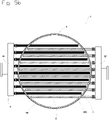
- Filter 1 of the figure 5a is a simple star filter according to the invention, the plates 2 of which, all identical, are connected in independent groups to two separate external collectors 5 . Thus, one half of the plates 2 is connected to a first outer collector 50 and the second half to the second outer collector 51.
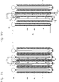
- Filter 1 of the figure 5b is a filter according to the invention whose plates 2 are arranged in parallel and are connected in independent groups to two separate external manifolds 5.
- one half of the trays 2 is connected to a first outer collector 50 and the second half to the second outer collector 51.
- two consecutive trays 2 are connected to the two outer collectors 50 and 51.
- the trays 2 connected to the same outer collector 50 or 51 thus form an independent group of non-adjacent trays 2.
- the filter therefore comprises two independent groups of plates 2.
- a first independent group of plates 2 is represented in black on the figure 5a and on the figure 5b , and the second independent group of trays 2 is shown hatched.
- the filtration cycle of filter 1 breaks down into two phases: the filtration phase and the build-up phase.
- tank 3 of filter 1 is filled of the suspension to be filtered. Said tank 3 is then pressurized while the plates 2, via their tubing 200, are placed under vacuum.
- the liquid phase of the suspension then passes through the cloths 221 of the filtering elements 22, and the solid phase remains on the surface of said cloths 221, forming a cake 6.
- the cloths 221 are pressed against the drains 220 of the filter element 22.
- the filtration phase stops when the resistance of the cakes 6 to the flow of the liquid becomes too great.
- the most common deconstruction process is countercurrent filtrate deconstruction. Most often, the filtrate used is stored during the filtration phase in a balloon, called “blowing balloon", located above the filter 1. During the deconstruction phase, said filtrate is returned under the sole effect of gravity in all the filtering elements 22 of the filter 1, after venting the tank 3 of the said filter 1. Once detached from their filtering element 22, the cakes 6 decant within the suspension between the plates 2, until the bottom of filter 1, before being extracted.
- E2 is therefore less than E1 by more than 20%.
- the diagram shown figure 9 shows a first variant of the process for disassembling a filter 1 of the invention with three external collectors 5.
- the difference between the pressure inside the filtering elements 22 and the pressure outside the filtering elements 22, pressures measured by means of pressure transmitters PT, is regulated by the speed of rotation of the pump 7.
- a safety weir 70 in a gooseneck, connects the discharge from the pump 7 to the upper part of the tank 3 of the filter 1, through an automatic valve 71.
- the weir 70 is connected at its top to the cover 31 of the filter 1 to allow free circulation of the compressed air between cover 31 of tank 3 of filter 1 and weir 70.
- the height of weir 70 will physically determine the maximum allowable difference between the pressure inside the filter elements 22 and the pressure outside the elements. filtering elements 22. At any point of the filtering elements 22 of the group of plates 2 independent in the disassembly phase, the difference between the pressure inside and the pressure outside of said filtering elements 22 will therefore be lower than the pressure corresponding to the height of the weir 70 filled with blowing fluid.
- each of the three external collectors 50, 51, 52 is in communication with the general pipe 8 of filtrate through an automatic valve 720, 721, 722.
- that of the three external collectors 50, 51, 52 concerned is in communication with the discharge of the pump 7 through an automatic valve 730, 731, 732. If the discharge pressure of the pump 7 was such that the maximum authorized difference between the pressure inside the filtering elements 22 and the pressure at the outside of the filtering elements 22 was reached, any risk of overflow would be avoided thanks to the discharge of the excess blowing fluid into the tank 3 of the filter 1 through the weir 70.
- the diagram shown figure 10 shows a second variant of the process for disassembling a filter 1 of the invention with three external collectors 5.
- a self-propelled compressed air differential pressure regulator 74 installed on the compressed air supply of the pressurized balloon 75 filled with filtrate.
- the low pressure impulse line 741 of the regulator 74 is connected to the cover 31 of the filter 1.
- the high pressure impulse line 742 of the regulator 74 is connected to the compressed air supply of the pressurized balloon 75, downstream of the regulator 74 and upstream of the automatic isolation valve 752.
- a gooseneck safety overflow 70 connects the bottom of the pressurized balloon 75 to the upper part of the tank 3 of the filter 1, through a valve 71.
- Weir 70 is connected at its top to cover 31 of filter 1 to allow free circulation of compressed air between cover 31 of tank 3 of filter 1 and weir 70.
- the height of weir 70 will physically determine the maximum authorized difference between the pressure inside the filtering elements 22 and the pressure outside the filtering elements 22. At any point of the filtering elements 22 of the group of plates 2 independent in be the pressure inside and the pressure outside of said filter elements 22 will therefore be lower than the pressure corresponding to the height of the weir 70 filled with blowing fluid.
- each of the three external collectors 50, 51, 52 is in communication with the general pipe 8 of filtrate through an automatic valve 720, 721, 722.
- that of the three external collectors 50, 51, 52 concerned is put in communication with the pressurized tank 75 through an automatic valve 730, 731, 732.
- the pressurized flask 75 fills with filtrate, automatic vent valve 751 open and automatic isolation valve 752 closed.
- the automatic vent valve 751 closes and the automatic isolation valve 752 opens to allow regulation of the difference between the pressure inside the filter elements 22 and the pressure outside the filter elements 22, thus beginning the building phase.
- the diagram shown figure 11 shows a third variant of the process for disassembling a filter 1 of the invention with three external collectors 5.
- the difference between the pressure inside the filter elements 22 and the pressure outside the filter elements 22 comes from the difference between the level of filtrate in the balloon 76 and the level of suspension in the filter 1.
- the balloon 76 is connected at its top to the cover 31 of the filter 1 through an automatic balancing valve 77 to allow free circulation of compressed air between the lid 31 of the tank 3 of the filter 1 and the balloon 76 during the building removal phases.
- the height of the balloon 76 will physically determine the maximum allowable difference between the pressure inside the elements filters 22 and the pressure outside the filter elements 22.
- the difference between the pressure inside and the pressure outside of said elements filters 22 will therefore be lower than the pressure corresponding to the height of the balloon 76 filled with blowing fluid.
- each of the three external collectors 50, 51, 52 is in communication with the general pipe 8 of filtrate through an automatic valve 720, 721, 722. .
- that of the three external collectors 50, 51, 52 concerned is placed in communication with the tank 76 through an automatic valve 730, 731, 732 Flask 76 fills with filtrate, automatic vent valve 78 open and automatic balancing valve 77 closed.
- the automatic vent valve 78 closes and the automatic balancing valve 77 opens to balance the pressure at the top of the filter 1 and the pressure at the top of the tank 76, thus starting the dismantling phase.
- the balloon sends the filtrate, under the sole effect of gravity, into the outer collector 50, 51, 52 concerned.
- the suspension level in filter 1 measured on the LT level transmitter, increases.
- a setpoint suspension level in filter 1 is restored after each build-up phase by adding compressed air to the top of filter 1 through automatic valve 9.
- the height of balloon 76 is provided so that the maximum authorized difference between the pressure inside the filter elements 22 and the pressure outside the filter elements 22 is never exceeded.
- the diagram shown figure 12 shows a fourth variant of the process for disassembling a filter 1 of the invention with three external collectors 5.
- the difference between the pressure inside the filter elements 22 and the pressure outside the elements filters 22 comes from the difference between the level of filtrate in one of the balloons 760, 761, 762 and the level of suspension in the filter 1.
- the balloons 760, 761,762 are connected at their top to the cover 31 of the filter 1 through an automatic balancing valve 770, 771, 772 to allow free circulation of compressed air between cover 31 of tank 3 of filter 1 and one of balloons 760, 761, 762 during building removal phases .
- the height of the balloons 760, 761, 762 will physically determine the maximum difference allowed between the pressure inside the filter elements 22 and the pressure outside the filter elements 22. At any point of the filter elements 22 of the group of plates 2 independent in the build-up phase, the difference between the pressure inside and the pressure outside said filter elements 22 will therefore be lower than the pressure corresponding to the height of the balloons 760, 761, 762 filled with blowing fluid.
- each of the three external collectors 50, 51, 52 is in communication with the general pipe 8 of filtrate through a balloon 760, 761, 762 which is connected to it. clean, of the overflow 7600, 7610, 7620 of said balloon 761, 762, 763 and of the filtrate outlet valve 790, 791, 792 of said balloon 761, 762, 763.
- that of the three external collectors 50, 51, 52 concerned is in direct communication with its balloon 760, 761, 762.
- the automatic vent valve 780, 781, 782 and the automatic outlet valve of filtrate of said balloon 760, 761, 762 close and the automatic balancing valve 770, 771, 772 of said balloon 760, 761, 762 opens to balance the pressure at the top of filter 1 and the pressure at the top of said balloon 760, 761, 762, thus beginning the dismantling phase.
- the balloon 760, 761, 762 sends the filtrate, under the sole effect of gravity, into the outer collector 50, 51, 52 concerned.
- the suspension level in filter 1, measured on the LT level transmitter, increases.
- a set suspension level in filter 1 is restored after each deconstruction phase by adding compressed air to the top of the filter 1 through the automatic valve 9.
- the height of the balloons 760, 761, 762 is provided so that the maximum authorized difference between the pressure inside the filter elements 22 and the pressure outside the filter elements 22 is never exceeded.
Landscapes
- Chemical & Material Sciences (AREA)
- Chemical Kinetics & Catalysis (AREA)
- Filtration Of Liquid (AREA)
Claims (16)
- Filter (1) mit vertikalen Platten (2), umfassend einen Behälter (3), in dem die Platten (2) vertikal im Inneren des Behälters (3) aufgehängt sind, wobei jede Platte (2) einen Schlauch (200) umfasst, der mit einem bezüglich des Behälters (3) externen Sammelbehälter (5, 50, 51, 52) zur Evakuierung des Filtrats verbunden ist, wobei der Filter dadurch gekennzeichnet ist, dass er N externe Sammelbehälter (5, 50, 51, 52) umfasst, wobei N größer oder gleich 2 ist, dass bezüglich aller Platten (2) zwei angrenzende Platten (2) mit zwei unterschiedlichen externen Sammelbehältern (5, 50, 51, 52) verbunden sind, so dass die mit einem selben externen Sammelbehälter (5, 50, 51, 52) verbundenen Platten (2) auf diese Weise eine von den nicht angrenzenden Platten (2) unabhängige Gruppe bilden, deren Platten (2) gleichzeitig abgelöst werden können, wobei jeder abgelöste Kuchen (6) einem Kuchen (6) gegenübersteht, der gerade gebildet wird, wobei der Filter (1) N unabhängige Plattengruppen (2) umfasst, die durch Aufbau eines Gegenblasstroms abwechselnd in jedem der N externen Sammelbehälter (5, 50, 51, 52) ablösbar sind, und dass jede Platte (2) mindestens ein Filterelement (22) umfasst, wobei jedes Filterelement (22) aus mindestens zwei Abflüssen (220) und einem Netz (221) besteht, wobei das Netz (221) Kammern (222) aufweist, wobei in jede der Kammern ein Abfluss (220) eingeführt ist, wobei jeder Abfluss (220) in einer in dem Netz (221) ausgeführten Kammer (222) angeordnet ist, diese Kammern (222) beispielsweise mit Nähten oder Schweißnähten (223) auf dem Netz (221) ausgeführt werden können, so dass, während der Filterphase, das Netz (221) auf den Abflüssen (220) sitzt und, während der Blasphase, sich das Netz (221) aufbläht und von den Abflüssen (220) entfernt, wobei die Kammern (222) so ausgeführt sind, dass ihre Enge ein schwaches Aufblähen des Netzes (221) zulässt, um ein Annähern der Filterelemente (22) zueinander zu ermöglichen.
- Filter (1) nach dem vorangehenden Anspruch, dadurch gekennzeichnet, dass die Platten (2) sternförmig angeordnet sind.
- Filter (1) nach dem vorangehenden Anspruch, dadurch gekennzeichnet, dass jeder externe Sammelbehälter (5) den Filter (1) umkreist.
- Filter (1) nach Anspruch 2 oder 3, dadurch gekennzeichnet, dass er eine Abfolge von doppelten Platten (21) auf zwei Filterelemente (22), die einen langen Schlauch (200) umfassen, und aus einfachen Platten (20) auf ein Filterelement (22), das einen kurzen Schlauch (200) umfasst, umfasst, und dass jede einfache Platte (20) mit einer doppelten Platte (21) verbunden ist, so dass sie so Plattenpaare (2) bilden, dass die einfachen Platten (20) am Innenumfang des Behälters (3), in dem Raum, der von den doppelten Platten (21) freigelassen wird, aufgenommen sind.
- Filter (1) nach dem vorangehenden Anspruch, dadurch gekennzeichnet, dass der kurze Schlauch (200) einer einfachen Platte (20) mit dem langen Schlauch (200) einer doppelten Platte (21) durch eine Leitung (23) verbunden ist, die die beiden Platten (2) verbindet.
- Filter nach einem der Ansprüche 4 oder 5, dadurch gekennzeichnet, dass jedes Plattenpaar (2) über den Schlauch der doppelten Platte (21) mit einem einzigen externen Sammelbehälter (5, 50, 51, 52) verbunden ist.
- Filter (1) nach einem der Ansprüche 3 bis 6, dadurch gekennzeichnet, dass N größer oder gleich drei ist.
- Filter (1) nach dem vorangehenden Anspruch, dadurch gekennzeichnet, dass bezüglich aller Plattenpaare (2) N aufeinanderfolgende Plattenpaare (2) mit N externen Sammelbehältern (5, 50, 51, 52) verbunden sind, und dass die einfache Platte (20) und die doppelte Platte (21) eines selben Paares durch eine gerade Anzahl an Platten (2) beabstandet sind.
- Verfahren zum Ablösen von Kuchen (6) eines Filters (1) nach einem der vorangehenden Ansprüche, dadurch gekennzeichnet, dass jeder externe Sammelbehälter (5, 50, 51, 52) durch einen Filtratstrom durchlaufen wird, der sich gemäß einem vordefinierten Zyklus umkehrt, und dass die Zyklen aller externen Sammelbehälter untereinander identisch und phasenverschoben sind, dass in jeder Ablösephase nur die Platten (2) einer unabhängigen Plattengruppe (2) abgelöst werden, die nicht aneinander angrenzen und mit einem einzigen externen Sammelbehälter (5, 50, 51, 52) verbunden sind, indem ein Aufblähen des Netzes (221) jeder Kammer (222) hervorgerufen wird, damit es sich von den Abflüssen (220) entfernt, wobei die anderen Platten (2) phasengleich mit der Filtration bleiben, während der das Netz (221) jeder Kammer (222) auf den Abflüssen (220) sitzt, wodurch eine kontinuierliche Extraktion des Filtrats sichergestellt wird, so dass zwei angrenzende Platten (2) niemals zur selben Zeit abgelöst werden.
- Verfahren nach dem vorangehenden Anspruch, dadurch gekennzeichnet, dass die Zyklen der Filtratstromumkehrungen aller externen Sammelbehälter (5, 50, 51, 52) um ein selbes Zeitintervall phasenverschoben sind.
- Verfahren nach einem der Ansprüche 9 oder 10, dadurch gekennzeichnet, dass die Umkehrung des Filtratstroms mittels einer Pumpe (7) über einen Blaskreislauf erfolgt, der die Verdrängung der Pumpe (7) mit jedem der externen Sammelbehälter (5, 50, 51, 52) in Verbindung bringen kann.
- Verfahren nach einem der Ansprüche 9 oder 10, dadurch gekennzeichnet, dass die Umkehrung des Filtratstroms mittels eines unter Überdruck stehenden Ballons (75), der mit dem Filtrat gefüllt ist, über einen Blaskreislauf erfolgt, der den Ausgang des unter Überdruck stehenden Ballons (75) in Verbindung mit jedem der externen Sammelbehälter (5, 50, 51, 52) bringen kann.
- Verfahren nach einem der Ansprüche 11 oder 12, dadurch gekennzeichnet, dass der Blaskreislauf gleichzeitig mit einem Sicherheitsüberlauf (70) mit einer Höhe zwischen 1 m und 5 m über dem Filter (1) ausgestattet ist, der am oberen Teil des Behälters (3) des Filters (1) mit dem Inneren des Filters (1) verbunden ist.
- Verfahren nach einem der Ansprüche 9 oder 10, dadurch gekennzeichnet, dass die Umkehrung des Filtratstroms mittels eines mit dem Filtrat gefüllten Ballons (76), der beladen auf dem Filter (1) und in ihrem oberen Teil mit dem Behälter (3) des Filters (1) verbunden ist, erfolgt, wobei die Umkehrung über einen Blaskreislauf erfolgt, der den Ausgang des Ballons (76) in Verbindung mit jedem der externen Sammelbehälter (5, 50, 51, 52) bringen kann.
- Verfahren nach einem der Ansprüche 9 oder 10, dadurch gekennzeichnet, dass die Filtratstromumkehrung mittels von mit dem Filtrat gefüllten Ballons (760, 761, 762) erfolgt, die beladen auf dem Filter (1) und in ihrem oberen Teil mit dem Behälter (3) des Filters (1) verbunden sind, wobei die Umkehrung über Blaskreisläufe erfolgt, die jeweils den Ausgang eines einzigen der Ballons (760, 761, 762) in Verbindung mit einem einzigen der externen Sammelbehälter (5, 50, 51, 52) bringen können.
- Verfahren nach einem der Ansprüche 14 oder 15, dadurch gekennzeichnet, dass sich der obere Teil der Ballons (76, 760, 761, 762) zwischen 1 m und 5 m über dem Filter (1) befindet.
Applications Claiming Priority (2)
| Application Number | Priority Date | Filing Date | Title |
|---|---|---|---|
| PCT/FR2016/052797 WO2018078223A1 (fr) | 2016-10-27 | 2016-10-27 | Filtre a plateaux verticaux rapproches |
| PCT/FR2017/052963 WO2018078294A1 (fr) | 2016-10-27 | 2017-10-26 | Filtre a plateaux verticaux rapproches |
Publications (2)
| Publication Number | Publication Date |
|---|---|
| EP3532184A1 EP3532184A1 (de) | 2019-09-04 |
| EP3532184B1 true EP3532184B1 (de) | 2022-06-22 |
Family
ID=57543064
Family Applications (1)
| Application Number | Title | Priority Date | Filing Date |
|---|---|---|---|
| EP17801073.2A Active EP3532184B1 (de) | 2016-10-27 | 2017-10-26 | Dichter vertikaler plattenfilter |
Country Status (10)
| Country | Link |
|---|---|
| US (1) | US11173430B2 (de) |
| EP (1) | EP3532184B1 (de) |
| CN (1) | CN109937079B (de) |
| AU (1) | AU2017349329B2 (de) |
| BR (1) | BR112019008573B1 (de) |
| CA (1) | CA3041755A1 (de) |
| EA (1) | EA038713B1 (de) |
| ES (1) | ES2926470T3 (de) |
| PL (1) | PL3532184T3 (de) |
| WO (2) | WO2018078223A1 (de) |
Families Citing this family (7)
| Publication number | Priority date | Publication date | Assignee | Title |
|---|---|---|---|---|
| US11717775B2 (en) * | 2018-06-13 | 2023-08-08 | Cargill, Incorporated | Liquid discharge filter and its use |
| CN110548327B (zh) * | 2019-09-27 | 2022-05-10 | 杭州科百特过滤器材有限公司 | 一种用于高粘度熔体过滤的碟形过滤盘 |
| KR20210132921A (ko) * | 2020-04-28 | 2021-11-05 | 주식회사 아모그린텍 | 중력식 정수장치용 필터모듈 및 이를 포함하는 중력식 정수장치 |
| CN112023505A (zh) * | 2020-08-11 | 2020-12-04 | 孙悦 | 一种稀土氧化物生产用废水治理池清洗装置及其实施方法 |
| CN113813658B (zh) * | 2021-08-04 | 2022-08-26 | 长沙市市政工程有限责任公司 | 一种桥梁桩基施工用泥浆压滤机 |
| US12215555B2 (en) * | 2023-03-21 | 2025-02-04 | Saudi Arabian Oil Company | Systems and methods for operating candle filters to recover glycols from drilling operations |
| WO2025125732A1 (fr) * | 2023-12-15 | 2025-06-19 | Gaudfrin | Filtre a plateaux |
Family Cites Families (14)
| Publication number | Priority date | Publication date | Assignee | Title |
|---|---|---|---|---|
| GB270616A (en) * | 1926-06-11 | 1927-05-12 | Oliver Continuous Filter Compa | Improvements in and connected with pulp thickeners or filters |
| DE1082575B (de) * | 1958-06-25 | 1960-06-02 | Krauss Maffei Imp G M B H & Co | Rohreindicker zum Eindicken von Masse-Suspensionen |
| US2974748A (en) * | 1959-12-16 | 1961-03-14 | Day Company | Air filter |
| FR1425376A (fr) * | 1964-12-02 | 1966-01-24 | Fives Lille Cail | Filtre épaississeur à marche continue |
| GB2094653A (en) * | 1981-03-13 | 1982-09-22 | Johnson Willard Lewis | Alternately operated sets of filters in filter tank |
| DE3340952C2 (de) * | 1983-11-11 | 1994-12-01 | Sanshin Mfg Co Ltd | Filtereinheit |
| FR2588765B1 (fr) * | 1985-10-17 | 1988-01-15 | Gaudfrin Guy | Filtre pour liquides charges de particules solides et installation de filtration comprenant un tel filtre |
| US4790935A (en) * | 1986-11-26 | 1988-12-13 | Johnson Willard L | Filter leaf assembly with bonded spacer and sealer |
| US4861498A (en) * | 1987-12-30 | 1989-08-29 | R & L Filtration Limited | Backwash system for filter-thickeners |
| DE19734588A1 (de) * | 1997-08-09 | 1999-02-11 | Boll & Kirch Filter | Rückspülfilter |
| ES2379276T3 (es) * | 2004-09-23 | 2012-04-24 | Guy Gaudfrin | Elemento filtrante para líquidos e instalación de filtración que comprende dicho elemento |
| CN103100251A (zh) * | 2006-05-02 | 2013-05-15 | 比吉尔·尼尔森 | 从大流量流动液体分离和过滤颗粒及有机物的装置和方法 |
| CN201921580U (zh) * | 2010-09-14 | 2011-08-10 | 高敏 | 一种叶滤机过滤装置 |
| CN105817063A (zh) * | 2016-01-08 | 2016-08-03 | 南通航泰船舶机械有限公司 | 一种系统压差驱动型反冲洗滤器 |
-
2016
- 2016-10-27 WO PCT/FR2016/052797 patent/WO2018078223A1/fr not_active Ceased
-
2017
- 2017-10-26 US US16/345,944 patent/US11173430B2/en active Active
- 2017-10-26 ES ES17801073T patent/ES2926470T3/es active Active
- 2017-10-26 BR BR112019008573-4A patent/BR112019008573B1/pt active IP Right Grant
- 2017-10-26 EP EP17801073.2A patent/EP3532184B1/de active Active
- 2017-10-26 CN CN201780069358.1A patent/CN109937079B/zh active Active
- 2017-10-26 PL PL17801073.2T patent/PL3532184T3/pl unknown
- 2017-10-26 WO PCT/FR2017/052963 patent/WO2018078294A1/fr not_active Ceased
- 2017-10-26 CA CA3041755A patent/CA3041755A1/fr active Pending
- 2017-10-26 EA EA201990786A patent/EA038713B1/ru unknown
- 2017-10-26 AU AU2017349329A patent/AU2017349329B2/en active Active
Also Published As
| Publication number | Publication date |
|---|---|
| WO2018078223A1 (fr) | 2018-05-03 |
| AU2017349329A1 (en) | 2019-06-13 |
| EP3532184A1 (de) | 2019-09-04 |
| BR112019008573A2 (pt) | 2019-07-09 |
| ES2926470T3 (es) | 2022-10-26 |
| CN109937079B (zh) | 2021-12-07 |
| BR112019008573B1 (pt) | 2023-03-07 |
| US20190329163A1 (en) | 2019-10-31 |
| WO2018078294A1 (fr) | 2018-05-03 |
| PL3532184T3 (pl) | 2022-11-28 |
| US11173430B2 (en) | 2021-11-16 |
| CA3041755A1 (fr) | 2018-05-03 |
| AU2017349329B2 (en) | 2020-01-30 |
| EA201990786A1 (ru) | 2019-11-29 |
| EA038713B1 (ru) | 2021-10-08 |
| CN109937079A (zh) | 2019-06-25 |
Similar Documents
| Publication | Publication Date | Title |
|---|---|---|
| EP3532184B1 (de) | Dichter vertikaler plattenfilter | |
| CA1325181C (fr) | Separateur pour deux liquides non miscibles | |
| EP0226478B1 (de) | Filter zum Abscheiden von Festkörperteilchen und damit ausgerüstete Filteranlage | |
| EP2585188B1 (de) | Modulare vorrichtung zur flüssig-flüssig-schwerkrafttrennung | |
| WO2012146730A1 (fr) | Dispositif d'extraction de matériau solide sur le fond d'une étendue d'eau et procédé associé | |
| WO2014044978A1 (fr) | Unité sous-marine de traitement de l'eau et procédé de nettoyage de ladite unité | |
| EP0120750B1 (de) | Vorrichtung zur tangentialen Filterung und diese Vorrichtung umfassende Anlage | |
| WO2012150390A1 (fr) | Procédé pour la récolte de microalgues et dispositif pour la mise en oeuvre de ce procédé | |
| WO2018096296A1 (fr) | Systeme de filtration d'une solution comportant des microalgues en vue de leur recolte | |
| CA2338174C (fr) | Procede et dispositif de filtration d'eau par membrane | |
| EP3138620B1 (de) | Filterverfahren in einer membranfilterpresse | |
| TWM520939U (zh) | 膜模組 | |
| FR2708423A1 (fr) | Procédé de vinification du raisin, ensemble de pressurage indépendant et drain amovible convenant à la mise en Óoeuvre de ce procédé. | |
| EP2164808B1 (de) | Autonome meerwasserreinigungsvorrichtung mit alternierend untergetauchten filterungsmodulen mit mehrkolben-unterdruckkammern | |
| EP0147320A2 (de) | Entgasungsvorrichtung | |
| WO2019038467A1 (en) | LIQUID FILTRATION APPARATUS | |
| EP2889069A2 (de) | Filter für frei fließende Flüssigkeit | |
| US1334692A (en) | Bag-filter | |
| JP5944195B2 (ja) | バラスト水の膜処理方法及び膜処理方法 | |
| BE540923A (de) | ||
| FR3011544A1 (fr) | Dispositif et procede d'epaississement de boue | |
| CH106207A (fr) | Procédé de filtrage de liquides contenant des matières solides en suspension et installation pour la mise en oeuvre de ce procédé. | |
| JP2018183730A (ja) | 逆浸透膜ろ過装置および逆浸透膜の洗浄方法 | |
| BE332667A (de) | ||
| BE624270A (fr) | Perfectionnements relatifs aux filtres. |
Legal Events
| Date | Code | Title | Description |
|---|---|---|---|
| STAA | Information on the status of an ep patent application or granted ep patent |
Free format text: STATUS: UNKNOWN |
|
| STAA | Information on the status of an ep patent application or granted ep patent |
Free format text: STATUS: THE INTERNATIONAL PUBLICATION HAS BEEN MADE |
|
| PUAI | Public reference made under article 153(3) epc to a published international application that has entered the european phase |
Free format text: ORIGINAL CODE: 0009012 |
|
| STAA | Information on the status of an ep patent application or granted ep patent |
Free format text: STATUS: REQUEST FOR EXAMINATION WAS MADE |
|
| 17P | Request for examination filed |
Effective date: 20190520 |
|
| AK | Designated contracting states |
Kind code of ref document: A1 Designated state(s): AL AT BE BG CH CY CZ DE DK EE ES FI FR GB GR HR HU IE IS IT LI LT LU LV MC MK MT NL NO PL PT RO RS SE SI SK SM TR |
|
| AX | Request for extension of the european patent |
Extension state: BA ME |
|
| DAV | Request for validation of the european patent (deleted) | ||
| DAX | Request for extension of the european patent (deleted) | ||
| STAA | Information on the status of an ep patent application or granted ep patent |
Free format text: STATUS: EXAMINATION IS IN PROGRESS |
|
| 17Q | First examination report despatched |
Effective date: 20200515 |
|
| GRAP | Despatch of communication of intention to grant a patent |
Free format text: ORIGINAL CODE: EPIDOSNIGR1 |
|
| STAA | Information on the status of an ep patent application or granted ep patent |
Free format text: STATUS: GRANT OF PATENT IS INTENDED |
|
| RAP3 | Party data changed (applicant data changed or rights of an application transferred) |
Owner name: GAUDFRIN |
|
| RIN1 | Information on inventor provided before grant (corrected) |
Inventor name: GAUDFRIN, GUY |
|
| INTG | Intention to grant announced |
Effective date: 20220131 |
|
| GRAS | Grant fee paid |
Free format text: ORIGINAL CODE: EPIDOSNIGR3 |
|
| GRAA | (expected) grant |
Free format text: ORIGINAL CODE: 0009210 |
|
| STAA | Information on the status of an ep patent application or granted ep patent |
Free format text: STATUS: THE PATENT HAS BEEN GRANTED |
|
| AK | Designated contracting states |
Kind code of ref document: B1 Designated state(s): AL AT BE BG CH CY CZ DE DK EE ES FI FR GB GR HR HU IE IS IT LI LT LU LV MC MK MT NL NO PL PT RO RS SE SI SK SM TR |
|
| REG | Reference to a national code |
Ref country code: GB Ref legal event code: FG4D Free format text: NOT ENGLISH |
|
| REG | Reference to a national code |
Ref country code: CH Ref legal event code: EP |
|
| REG | Reference to a national code |
Ref country code: DE Ref legal event code: R096 Ref document number: 602017058800 Country of ref document: DE |
|
| REG | Reference to a national code |
Ref country code: AT Ref legal event code: REF Ref document number: 1499394 Country of ref document: AT Kind code of ref document: T Effective date: 20220715 |
|
| REG | Reference to a national code |
Ref country code: IE Ref legal event code: FG4D Free format text: LANGUAGE OF EP DOCUMENT: FRENCH |
|
| REG | Reference to a national code |
Ref country code: SE Ref legal event code: TRGR |
|
| REG | Reference to a national code |
Ref country code: LT Ref legal event code: MG9D |
|
| REG | Reference to a national code |
Ref country code: NL Ref legal event code: MP Effective date: 20220622 Ref country code: ES Ref legal event code: FG2A Ref document number: 2926470 Country of ref document: ES Kind code of ref document: T3 Effective date: 20221026 Ref country code: GR Ref legal event code: EP Ref document number: 20220401790 Country of ref document: GR Effective date: 20221010 |
|
| PG25 | Lapsed in a contracting state [announced via postgrant information from national office to epo] |
Ref country code: NO Free format text: LAPSE BECAUSE OF FAILURE TO SUBMIT A TRANSLATION OF THE DESCRIPTION OR TO PAY THE FEE WITHIN THE PRESCRIBED TIME-LIMIT Effective date: 20220922 Ref country code: LT Free format text: LAPSE BECAUSE OF FAILURE TO SUBMIT A TRANSLATION OF THE DESCRIPTION OR TO PAY THE FEE WITHIN THE PRESCRIBED TIME-LIMIT Effective date: 20220622 Ref country code: HR Free format text: LAPSE BECAUSE OF FAILURE TO SUBMIT A TRANSLATION OF THE DESCRIPTION OR TO PAY THE FEE WITHIN THE PRESCRIBED TIME-LIMIT Effective date: 20220622 Ref country code: FI Free format text: LAPSE BECAUSE OF FAILURE TO SUBMIT A TRANSLATION OF THE DESCRIPTION OR TO PAY THE FEE WITHIN THE PRESCRIBED TIME-LIMIT Effective date: 20220622 Ref country code: BG Free format text: LAPSE BECAUSE OF FAILURE TO SUBMIT A TRANSLATION OF THE DESCRIPTION OR TO PAY THE FEE WITHIN THE PRESCRIBED TIME-LIMIT Effective date: 20220922 |
|
| PG25 | Lapsed in a contracting state [announced via postgrant information from national office to epo] |
Ref country code: RS Free format text: LAPSE BECAUSE OF FAILURE TO SUBMIT A TRANSLATION OF THE DESCRIPTION OR TO PAY THE FEE WITHIN THE PRESCRIBED TIME-LIMIT Effective date: 20220622 Ref country code: LV Free format text: LAPSE BECAUSE OF FAILURE TO SUBMIT A TRANSLATION OF THE DESCRIPTION OR TO PAY THE FEE WITHIN THE PRESCRIBED TIME-LIMIT Effective date: 20220622 |
|
| PG25 | Lapsed in a contracting state [announced via postgrant information from national office to epo] |
Ref country code: NL Free format text: LAPSE BECAUSE OF FAILURE TO SUBMIT A TRANSLATION OF THE DESCRIPTION OR TO PAY THE FEE WITHIN THE PRESCRIBED TIME-LIMIT Effective date: 20220622 |
|
| PG25 | Lapsed in a contracting state [announced via postgrant information from national office to epo] |
Ref country code: SM Free format text: LAPSE BECAUSE OF FAILURE TO SUBMIT A TRANSLATION OF THE DESCRIPTION OR TO PAY THE FEE WITHIN THE PRESCRIBED TIME-LIMIT Effective date: 20220622 Ref country code: SK Free format text: LAPSE BECAUSE OF FAILURE TO SUBMIT A TRANSLATION OF THE DESCRIPTION OR TO PAY THE FEE WITHIN THE PRESCRIBED TIME-LIMIT Effective date: 20220622 Ref country code: RO Free format text: LAPSE BECAUSE OF FAILURE TO SUBMIT A TRANSLATION OF THE DESCRIPTION OR TO PAY THE FEE WITHIN THE PRESCRIBED TIME-LIMIT Effective date: 20220622 Ref country code: PT Free format text: LAPSE BECAUSE OF FAILURE TO SUBMIT A TRANSLATION OF THE DESCRIPTION OR TO PAY THE FEE WITHIN THE PRESCRIBED TIME-LIMIT Effective date: 20221024 Ref country code: EE Free format text: LAPSE BECAUSE OF FAILURE TO SUBMIT A TRANSLATION OF THE DESCRIPTION OR TO PAY THE FEE WITHIN THE PRESCRIBED TIME-LIMIT Effective date: 20220622 Ref country code: CZ Free format text: LAPSE BECAUSE OF FAILURE TO SUBMIT A TRANSLATION OF THE DESCRIPTION OR TO PAY THE FEE WITHIN THE PRESCRIBED TIME-LIMIT Effective date: 20220622 |
|
| PG25 | Lapsed in a contracting state [announced via postgrant information from national office to epo] |
Ref country code: IS Free format text: LAPSE BECAUSE OF FAILURE TO SUBMIT A TRANSLATION OF THE DESCRIPTION OR TO PAY THE FEE WITHIN THE PRESCRIBED TIME-LIMIT Effective date: 20221022 |
|
| REG | Reference to a national code |
Ref country code: DE Ref legal event code: R097 Ref document number: 602017058800 Country of ref document: DE |
|
| PG25 | Lapsed in a contracting state [announced via postgrant information from national office to epo] |
Ref country code: AL Free format text: LAPSE BECAUSE OF FAILURE TO SUBMIT A TRANSLATION OF THE DESCRIPTION OR TO PAY THE FEE WITHIN THE PRESCRIBED TIME-LIMIT Effective date: 20220622 |
|
| PG25 | Lapsed in a contracting state [announced via postgrant information from national office to epo] |
Ref country code: DK Free format text: LAPSE BECAUSE OF FAILURE TO SUBMIT A TRANSLATION OF THE DESCRIPTION OR TO PAY THE FEE WITHIN THE PRESCRIBED TIME-LIMIT Effective date: 20220622 |
|
| PLBE | No opposition filed within time limit |
Free format text: ORIGINAL CODE: 0009261 |
|
| STAA | Information on the status of an ep patent application or granted ep patent |
Free format text: STATUS: NO OPPOSITION FILED WITHIN TIME LIMIT |
|
| 26N | No opposition filed |
Effective date: 20230323 |
|
| PG25 | Lapsed in a contracting state [announced via postgrant information from national office to epo] |
Ref country code: MC Free format text: LAPSE BECAUSE OF FAILURE TO SUBMIT A TRANSLATION OF THE DESCRIPTION OR TO PAY THE FEE WITHIN THE PRESCRIBED TIME-LIMIT Effective date: 20220622 |
|
| REG | Reference to a national code |
Ref country code: CH Ref legal event code: PL |
|
| REG | Reference to a national code |
Ref country code: BE Ref legal event code: MM Effective date: 20221031 |
|
| GBPC | Gb: european patent ceased through non-payment of renewal fee |
Effective date: 20221026 |
|
| PG25 | Lapsed in a contracting state [announced via postgrant information from national office to epo] |
Ref country code: LU Free format text: LAPSE BECAUSE OF NON-PAYMENT OF DUE FEES Effective date: 20221026 |
|
| PG25 | Lapsed in a contracting state [announced via postgrant information from national office to epo] |
Ref country code: LI Free format text: LAPSE BECAUSE OF NON-PAYMENT OF DUE FEES Effective date: 20221031 Ref country code: CH Free format text: LAPSE BECAUSE OF NON-PAYMENT OF DUE FEES Effective date: 20221031 |
|
| REG | Reference to a national code |
Ref country code: AT Ref legal event code: UEP Ref document number: 1499394 Country of ref document: AT Kind code of ref document: T Effective date: 20220622 |
|
| PG25 | Lapsed in a contracting state [announced via postgrant information from national office to epo] |
Ref country code: SI Free format text: LAPSE BECAUSE OF FAILURE TO SUBMIT A TRANSLATION OF THE DESCRIPTION OR TO PAY THE FEE WITHIN THE PRESCRIBED TIME-LIMIT Effective date: 20220622 |
|
| PG25 | Lapsed in a contracting state [announced via postgrant information from national office to epo] |
Ref country code: BE Free format text: LAPSE BECAUSE OF NON-PAYMENT OF DUE FEES Effective date: 20221031 |
|
| PG25 | Lapsed in a contracting state [announced via postgrant information from national office to epo] |
Ref country code: IE Free format text: LAPSE BECAUSE OF NON-PAYMENT OF DUE FEES Effective date: 20221026 Ref country code: GB Free format text: LAPSE BECAUSE OF NON-PAYMENT OF DUE FEES Effective date: 20221026 |
|
| PG25 | Lapsed in a contracting state [announced via postgrant information from national office to epo] |
Ref country code: HU Free format text: LAPSE BECAUSE OF FAILURE TO SUBMIT A TRANSLATION OF THE DESCRIPTION OR TO PAY THE FEE WITHIN THE PRESCRIBED TIME-LIMIT; INVALID AB INITIO Effective date: 20171026 |
|
| PG25 | Lapsed in a contracting state [announced via postgrant information from national office to epo] |
Ref country code: CY Free format text: LAPSE BECAUSE OF FAILURE TO SUBMIT A TRANSLATION OF THE DESCRIPTION OR TO PAY THE FEE WITHIN THE PRESCRIBED TIME-LIMIT Effective date: 20220622 |
|
| PG25 | Lapsed in a contracting state [announced via postgrant information from national office to epo] |
Ref country code: MK Free format text: LAPSE BECAUSE OF FAILURE TO SUBMIT A TRANSLATION OF THE DESCRIPTION OR TO PAY THE FEE WITHIN THE PRESCRIBED TIME-LIMIT Effective date: 20220622 |
|
| PG25 | Lapsed in a contracting state [announced via postgrant information from national office to epo] |
Ref country code: TR Free format text: LAPSE BECAUSE OF FAILURE TO SUBMIT A TRANSLATION OF THE DESCRIPTION OR TO PAY THE FEE WITHIN THE PRESCRIBED TIME-LIMIT Effective date: 20220622 |
|
| PG25 | Lapsed in a contracting state [announced via postgrant information from national office to epo] |
Ref country code: MT Free format text: LAPSE BECAUSE OF FAILURE TO SUBMIT A TRANSLATION OF THE DESCRIPTION OR TO PAY THE FEE WITHIN THE PRESCRIBED TIME-LIMIT Effective date: 20220622 |
|
| PG25 | Lapsed in a contracting state [announced via postgrant information from national office to epo] |
Ref country code: BG Free format text: LAPSE BECAUSE OF FAILURE TO SUBMIT A TRANSLATION OF THE DESCRIPTION OR TO PAY THE FEE WITHIN THE PRESCRIBED TIME-LIMIT Effective date: 20220622 |
|
| PG25 | Lapsed in a contracting state [announced via postgrant information from national office to epo] |
Ref country code: BG Free format text: LAPSE BECAUSE OF FAILURE TO SUBMIT A TRANSLATION OF THE DESCRIPTION OR TO PAY THE FEE WITHIN THE PRESCRIBED TIME-LIMIT Effective date: 20220622 |
|
| PGFP | Annual fee paid to national office [announced via postgrant information from national office to epo] |
Ref country code: DE Payment date: 20251020 Year of fee payment: 9 |
|
| PGFP | Annual fee paid to national office [announced via postgrant information from national office to epo] |
Ref country code: AT Payment date: 20251021 Year of fee payment: 9 |
|
| PGFP | Annual fee paid to national office [announced via postgrant information from national office to epo] |
Ref country code: IT Payment date: 20251031 Year of fee payment: 9 |
|
| PGFP | Annual fee paid to national office [announced via postgrant information from national office to epo] |
Ref country code: FR Payment date: 20251022 Year of fee payment: 9 |
|
| PGFP | Annual fee paid to national office [announced via postgrant information from national office to epo] |
Ref country code: GR Payment date: 20251021 Year of fee payment: 9 |
|
| PGFP | Annual fee paid to national office [announced via postgrant information from national office to epo] |
Ref country code: SE Payment date: 20251023 Year of fee payment: 9 |
|
| PGFP | Annual fee paid to national office [announced via postgrant information from national office to epo] |
Ref country code: PL Payment date: 20251010 Year of fee payment: 9 |
|
| PGFP | Annual fee paid to national office [announced via postgrant information from national office to epo] |
Ref country code: ES Payment date: 20251114 Year of fee payment: 9 |