EP3532184B1 - Dense vertical leaf filter - Google Patents
Dense vertical leaf filter Download PDFInfo
- Publication number
- EP3532184B1 EP3532184B1 EP17801073.2A EP17801073A EP3532184B1 EP 3532184 B1 EP3532184 B1 EP 3532184B1 EP 17801073 A EP17801073 A EP 17801073A EP 3532184 B1 EP3532184 B1 EP 3532184B1
- Authority
- EP
- European Patent Office
- Prior art keywords
- filter
- plates
- filtrate
- external
- tank
- Prior art date
- Legal status (The legal status is an assumption and is not a legal conclusion. Google has not performed a legal analysis and makes no representation as to the accuracy of the status listed.)
- Active
Links
- 241000638935 Senecio crassissimus Species 0.000 title 1
- 239000000706 filtrate Substances 0.000 claims description 60
- 238000001914 filtration Methods 0.000 claims description 60
- 238000007664 blowing Methods 0.000 claims description 29
- 238000000034 method Methods 0.000 claims description 28
- 239000004744 fabric Substances 0.000 claims description 23
- 238000004891 communication Methods 0.000 claims description 18
- 238000000605 extraction Methods 0.000 claims description 7
- 238000007599 discharging Methods 0.000 claims 2
- 239000012071 phase Substances 0.000 description 45
- 239000000725 suspension Substances 0.000 description 20
- 239000012530 fluid Substances 0.000 description 12
- 238000010586 diagram Methods 0.000 description 8
- 230000000694 effects Effects 0.000 description 5
- 230000005484 gravity Effects 0.000 description 5
- 239000007788 liquid Substances 0.000 description 4
- 238000002955 isolation Methods 0.000 description 3
- 239000007787 solid Substances 0.000 description 3
- 244000261422 Lysimachia clethroides Species 0.000 description 2
- 230000015572 biosynthetic process Effects 0.000 description 2
- 230000000149 penetrating effect Effects 0.000 description 2
- 230000001105 regulatory effect Effects 0.000 description 2
- 238000000926 separation method Methods 0.000 description 2
- 230000008961 swelling Effects 0.000 description 2
- 239000003570 air Substances 0.000 description 1
- 238000012550 audit Methods 0.000 description 1
- 238000010276 construction Methods 0.000 description 1
- 238000010908 decantation Methods 0.000 description 1
- 239000007791 liquid phase Substances 0.000 description 1
- 238000007789 sealing Methods 0.000 description 1
- 239000007790 solid phase Substances 0.000 description 1
- 238000011144 upstream manufacturing Methods 0.000 description 1
- 238000013022 venting Methods 0.000 description 1
- XLYOFNOQVPJJNP-UHFFFAOYSA-N water Substances O XLYOFNOQVPJJNP-UHFFFAOYSA-N 0.000 description 1
Images


Classifications
-
- B—PERFORMING OPERATIONS; TRANSPORTING
- B01—PHYSICAL OR CHEMICAL PROCESSES OR APPARATUS IN GENERAL
- B01D—SEPARATION
- B01D29/00—Filters with filtering elements stationary during filtration, e.g. pressure or suction filters, not covered by groups B01D24/00 - B01D27/00; Filtering elements therefor
- B01D29/39—Filters with filtering elements stationary during filtration, e.g. pressure or suction filters, not covered by groups B01D24/00 - B01D27/00; Filtering elements therefor with hollow discs side by side on, or around, one or more tubes, e.g. of the leaf type
- B01D29/395—Filters with filtering elements stationary during filtration, e.g. pressure or suction filters, not covered by groups B01D24/00 - B01D27/00; Filtering elements therefor with hollow discs side by side on, or around, one or more tubes, e.g. of the leaf type mounted axially on the tube
-
- B—PERFORMING OPERATIONS; TRANSPORTING
- B01—PHYSICAL OR CHEMICAL PROCESSES OR APPARATUS IN GENERAL
- B01D—SEPARATION
- B01D29/00—Filters with filtering elements stationary during filtration, e.g. pressure or suction filters, not covered by groups B01D24/00 - B01D27/00; Filtering elements therefor
- B01D29/50—Filters with filtering elements stationary during filtration, e.g. pressure or suction filters, not covered by groups B01D24/00 - B01D27/00; Filtering elements therefor with multiple filtering elements, characterised by their mutual disposition
- B01D29/52—Filters with filtering elements stationary during filtration, e.g. pressure or suction filters, not covered by groups B01D24/00 - B01D27/00; Filtering elements therefor with multiple filtering elements, characterised by their mutual disposition in parallel connection
- B01D29/54—Filters with filtering elements stationary during filtration, e.g. pressure or suction filters, not covered by groups B01D24/00 - B01D27/00; Filtering elements therefor with multiple filtering elements, characterised by their mutual disposition in parallel connection arranged concentrically or coaxially
-
- B—PERFORMING OPERATIONS; TRANSPORTING
- B01—PHYSICAL OR CHEMICAL PROCESSES OR APPARATUS IN GENERAL
- B01D—SEPARATION
- B01D35/00—Filtering devices having features not specifically covered by groups B01D24/00 - B01D33/00, or for applications not specifically covered by groups B01D24/00 - B01D33/00; Auxiliary devices for filtration; Filter housing constructions
- B01D35/16—Cleaning-out devices, e.g. for removing the cake from the filter casing or for evacuating the last remnants of liquid
-
- B—PERFORMING OPERATIONS; TRANSPORTING
- B01—PHYSICAL OR CHEMICAL PROCESSES OR APPARATUS IN GENERAL
- B01D—SEPARATION
- B01D29/00—Filters with filtering elements stationary during filtration, e.g. pressure or suction filters, not covered by groups B01D24/00 - B01D27/00; Filtering elements therefor
- B01D29/11—Filters with filtering elements stationary during filtration, e.g. pressure or suction filters, not covered by groups B01D24/00 - B01D27/00; Filtering elements therefor with bag, cage, hose, tube, sleeve or like filtering elements
- B01D29/13—Supported filter elements
- B01D29/15—Supported filter elements arranged for inward flow filtration
-
- B—PERFORMING OPERATIONS; TRANSPORTING
- B01—PHYSICAL OR CHEMICAL PROCESSES OR APPARATUS IN GENERAL
- B01D—SEPARATION
- B01D29/00—Filters with filtering elements stationary during filtration, e.g. pressure or suction filters, not covered by groups B01D24/00 - B01D27/00; Filtering elements therefor
- B01D29/62—Regenerating the filter material in the filter
- B01D29/66—Regenerating the filter material in the filter by flushing, e.g. counter-current air-bumps
- B01D29/668—Regenerating the filter material in the filter by flushing, e.g. counter-current air-bumps with valves, e.g. rotating valves for coaxially placed filtering elements
-
- B—PERFORMING OPERATIONS; TRANSPORTING
- B01—PHYSICAL OR CHEMICAL PROCESSES OR APPARATUS IN GENERAL
- B01D—SEPARATION
- B01D29/00—Filters with filtering elements stationary during filtration, e.g. pressure or suction filters, not covered by groups B01D24/00 - B01D27/00; Filtering elements therefor
- B01D29/88—Filters with filtering elements stationary during filtration, e.g. pressure or suction filters, not covered by groups B01D24/00 - B01D27/00; Filtering elements therefor having feed or discharge devices
- B01D29/94—Filters with filtering elements stationary during filtration, e.g. pressure or suction filters, not covered by groups B01D24/00 - B01D27/00; Filtering elements therefor having feed or discharge devices for discharging the filter cake, e.g. chutes
Definitions
- the present invention relates to a pressure filter with vertical plates with improved deconstruction making it possible to bring its plates closer together, and to its deconstruction method.
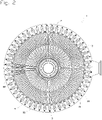
- filters whose plates are arranged in a star, there are some which only include plates comprising the same number of filtering elements. These filters are called “simple star”. There are also some which comprise alternating plates with two filtering elements comprising a long pipe, called “double plates”, and plates with one filtering element comprising a short pipe, called “single plates”. The single plates are housed at the inner periphery of the tank, in the space left free by the double plates. These filters are called "double star".
- the trays are immersed in the tank containing a suspension to be filtered.
- This tank is pressurized while the plates, via their tubing, are successively put under negative pressure to filter the suspension (filtration phase), then under overpressure to detach the "cake", that is to say the solid fraction of the suspension which has accumulated on the fabric during the filtration (deconstruction phase).
- filtration phase filter the suspension
- overpressure detach the "cake" that is to say the solid fraction of the suspension which has accumulated on the fabric during the filtration (deconstruction phase).
- Blowing When the build-up is done using a counter-current fluid, it is called "blowing".
- the object of the invention is to provide a filter that is both more compact and allows continuous extraction of the filtrate and does not have the above drawbacks.
- the vertical plate filter comprises plates each comprising a pipe connected to an external collector, said filter is characterized in that it comprises at least two external collectors, that, for all the plates, two adjacent plates are connected to two different external manifolds and that each plate comprises at least one filtering element, each filtering element consisting of at least two drains and a cloth, the cloth having compartments in each of which a drain is inserted.
- each filtering element consisting of at least two drains and a cloth, the cloth having compartments in each of which a drain is inserted.
- the plates of the filter are arranged in a star.
- the filter comprises an alternation of plates with two filtering elements comprising a long pipe, called “double plates”, and plates with one filtering element comprising a short pipe, called “single plates”.
- the single plates are housed at the inner periphery of the tank, in the space left free by the double plates. This makes it possible to increase the number of trays for the filters of large dimensions and therefore the filtration capacity.
- the filter is then called "double star”.
- each single plate is connected to a double plate, thus forming pairs of plates.
- the connection of single plates and double plates makes it possible to reduce by half the number of connections to the external collectors. This optimizes the space available outside the tank.
- the short tube of a single plate is connected to the long tube of a double plate by a conduit connecting the two plates.
- each pair of plates is connected to one and only one external collector through the tubing of the double plate.
- the mouth section of the tubing of the double platter is larger than that of the single platter. It can thus, in addition to its own flow of filtrate, take up the flow of filtrate extracted from the single plate during filtration, and, in addition to its own flow of blowing fluid, take up the flow of blowing fluid intended for the single plate during dismantling.
- the double star filter comprises N external collectors, N being greater than or equal to three. It is thus possible to apply blowing alternately to N groups of plates.
- N consecutive pairs of plates are connected to the N external collectors.
- the single tray and the double tray of the same pair are spaced by an even number of trays.
- the pairs of trays connected to the same external collector thus form a group of non-adjacent trays called "independent group of trays", the trays of which can be opened simultaneously.
- the filter therefore comprises N independent groups of plates which it is possible to build up by establishing the blowing counter-current alternately in each of the N external collectors.
- the single and double plates of the same pair are spaced of two trays. This arrangement makes it possible to build, in the filter comprising three external collectors, a tray every three trays, that is to say that when a tray is removed, the two adjacent trays and those which follow them directly are not removed. .
- the invention also relates to a process for removing the cakes of a vertical plate filter having at least one of the preceding characteristics, said process is characterized in that each external collector is traversed by a current of filtrate which is reversed according to a cycle predefined, and in that the cycles of all the external collectors are identical and out of phase with each other.
- the current inversions correspond to the passages from the filtration phase to the phase of deconstruction of the plates connected to this collector, and vice versa.
- At each deconstruction phase only the plates connected to a single external collector are deconstructed, the other plates remaining in the filtration phase, thus ensuring the continuity of the extraction of the filtrate. This ensures that two adjacent trays are never destroyed at the same time.
- the filtrate current inversion cycles of all the external collectors are out of phase by the same time interval.
- the filtration phases of each independent group of plates must be out of phase by the same time interval in order to limit variations in the flow rate of filtrate extracted from the filter.
- the inversion of the filtrate current is carried out by means of a pump, through a blowing circuit which can place the discharge of said pump in communication with each of the external collectors.
- This pump sends filtrate alternately into each of the external collectors at a pressure higher than that of the filter, thus putting the corresponding plates under overpressure to carry out their deconstruction.
- the inversion of the filtrate current is carried out by means of a pressurized balloon filled with said filtrate, through a blowing circuit capable of putting the outlet of said balloon on pressurized in communication with each of the external collectors.
- This over-pressurized balloon supplied with compressed air through a differential pressure regulator, sends filtrate alternately into each of the external collectors at a pressure higher than that of the filter, thus putting the corresponding plates under overpressure to proceed with their deconstruction.
- the blowing circuit is equipped in parallel with a safety spillway, of height between 1 and 5 m above the filter, connected inside the filter in the upper part of the tank of said filter.
- This safety overflow naturally limits the blowing overpressure in order to avoid any risk of damaging the filtering elements of the plates.
- the inversion of the filtrate current is carried out by means of a balloon filled with said filtrate, loaded on the filter and connected to the tank of said filter in their upper part, said inversion being carried out through a blowing circuit capable of putting the outlet of said balloon in communication with each of the external collectors.
- This balloon subjected to the same pressure as the filter by the communication of their upper part, sends filtrate, under the sole effect of gravity, alternately in each of the external collectors at a pressure higher than that of the filter, thus putting the corresponding trays under overpressure to proceed with their dismantling.
- the inversion of the filtrate current is carried out by means of balloons filled with said filtrate, loaded on the filter and connected to the tank of said filter in their upper part, said inversion being carried out through blowing circuits which can each putting the outlet of one and only one of said balloons in communication with one and only one of the external collectors.
- These balloons subjected to the same pressure as the filter by the communication of their upper part, send filtrate, under the sole effect of gravity, alternately in each of the collectors outside at a pressure higher than that of the filter, thus putting the corresponding plates under overpressure to proceed with their deconstruction.
- the upper part of the balloons is located between 1 and 5 m above the filter.
- the blowing overpressure is thus naturally limited in order to avoid any risk of damaging the filtering elements of the plates.
- a prior art filter 1, illustrated picture 2 Where picture 3 is a pressurized vertical 2-plate filter for the liquid/solid separation of a loaded suspension. It consists of a cylindrical tank 3 with a conical lower bottom 30 and a domed removable lid 31 shown on the figures 9 to 12 . The trays 2 are suspended vertically inside the tank 3 and arranged radially in a star.
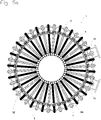
- the state-of-the-art small-diameter filters 1, illustrated picture 3 are equipped with plates 2 all identical, connected through the wall 32 of the tank 3 by bent tubes, called “filtrate outlets” 4, to an external collector 5 which goes around the filter (single star arrangement).
- the state-of-the-art large-diameter filters 1, illustrated picture 2 are equipped with plates 2 of two different types, plates 2 with one filtering element 22, called simple plates 20, and plates 2 with two filtering elements 22, called double plates 21. These simple plates 20 and these double plates 21 are connected through the wall 32 of the tank 3 by filtrate outlets 4, to an external collector 5 (double star arrangement). In this case, all the plates 2 are grouped together in pairs, a single plate 20 and a double plate 21 adjacent having a common filtrate outlet 4.
- Filter 1 of the figure 1 is a double star filter according to the invention, the vertical plates 2 of which are connected in independent groups to three separate external collectors 5 .
- a third of the single trays 20 and double trays 21 are connected to a first outer collector 50, a second third to a second outer collector 51, and the third third to the third outer collector 52.
- Each single tray 20 is connected to a double tray 21 via a conduit 23, thus forming a pair of tray.
- the double plate 21 of each pair is connected to one and only one external collector 5 by a filtrate outlet 4.
- the number N of outer collectors 5 is three.
- N being greater than or equal to three, there would be N independent groups of plates 2 each connected to one of the N external collectors 5.
- the filter therefore comprises three independent groups of plates 2.
- a first independent group of plates 2 is represented in black on the figure 4 , a second group in hatched, and the third group in white.
- a double tray 21 from the first group (black) is followed by a single tray 20 from the third group (white), then a double tray 21 from the second group (hatched), then a single tray 20 from the first group ( black), then a double 21 board from the third group (white), then a board single 20 from the second group (hatched), then a double 21 board from the first group (black) and so on.
- the single plates 20 and the double plates 21 of the same pair due to their distance, are no longer connected to each other through the wall 32 of the tank 3 as in the state of the art, but by means of a removable conduit 23 represented on the figure 4 in the color of the group of independent trays to which the conduit 23 belongs. In this arrangement, the filtering elements of the same group are never adjacent.
- the three modes of representation used highlight the different circulation circuits through the pipes 200, the conduits 23 and the filtrate outlets 4.
- the number N of external collectors 5 is three, and the single plate 20 and the double plate 21 of the same pair are spaced apart by two plates 2.
- N external collectors 5, N being greater than or equal to three the single tray 20 and the double tray 21 of the same pair will be spaced apart by two or another even number of trays 2.
- all the single plates 20 and all the double plates 21 respectively comprise one and two filtering elements 22 each consisting of drains 220 and a cloth 221. These filtering elements 22 are connected to the pipes 200 of the plates 2. Each conduit 23 connection connects said pipes 200 of the pairs of plates 2 by forming a bridge between them. Gaskets 230, placed between the pipes 200 and each of the two ends of the ducts 23 are compressed by wire springs 231 which exert sufficient force to guarantee sealing.
- the filter elements 22 comprise several drains 220, each drain being arranged in a compartment 222 made in the fabric 221. These compartments 222 can be made with, for example, seams or welds 223 on said fabric 221.
- filter elements 22 are detailed in the patent EP226478 incorporated by reference.
- the figure 6b shows in section the filtering element 22 where one can see that the compartments 222, due to their narrowness, will have a low swelling and thus make it possible to bring said filter elements closer to each other than conventional filter elements not comprising compartments 222.
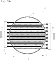
- Filter 1 of the figure 5a is a simple star filter according to the invention, the plates 2 of which, all identical, are connected in independent groups to two separate external collectors 5 . Thus, one half of the plates 2 is connected to a first outer collector 50 and the second half to the second outer collector 51.
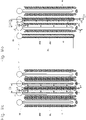
- Filter 1 of the figure 5b is a filter according to the invention whose plates 2 are arranged in parallel and are connected in independent groups to two separate external manifolds 5.
- one half of the trays 2 is connected to a first outer collector 50 and the second half to the second outer collector 51.
- two consecutive trays 2 are connected to the two outer collectors 50 and 51.
- the trays 2 connected to the same outer collector 50 or 51 thus form an independent group of non-adjacent trays 2.
- the filter therefore comprises two independent groups of plates 2.
- a first independent group of plates 2 is represented in black on the figure 5a and on the figure 5b , and the second independent group of trays 2 is shown hatched.
- the filtration cycle of filter 1 breaks down into two phases: the filtration phase and the build-up phase.
- tank 3 of filter 1 is filled of the suspension to be filtered. Said tank 3 is then pressurized while the plates 2, via their tubing 200, are placed under vacuum.
- the liquid phase of the suspension then passes through the cloths 221 of the filtering elements 22, and the solid phase remains on the surface of said cloths 221, forming a cake 6.
- the cloths 221 are pressed against the drains 220 of the filter element 22.
- the filtration phase stops when the resistance of the cakes 6 to the flow of the liquid becomes too great.
- the most common deconstruction process is countercurrent filtrate deconstruction. Most often, the filtrate used is stored during the filtration phase in a balloon, called “blowing balloon", located above the filter 1. During the deconstruction phase, said filtrate is returned under the sole effect of gravity in all the filtering elements 22 of the filter 1, after venting the tank 3 of the said filter 1. Once detached from their filtering element 22, the cakes 6 decant within the suspension between the plates 2, until the bottom of filter 1, before being extracted.
- E2 is therefore less than E1 by more than 20%.
- the diagram shown figure 9 shows a first variant of the process for disassembling a filter 1 of the invention with three external collectors 5.
- the difference between the pressure inside the filtering elements 22 and the pressure outside the filtering elements 22, pressures measured by means of pressure transmitters PT, is regulated by the speed of rotation of the pump 7.
- a safety weir 70 in a gooseneck, connects the discharge from the pump 7 to the upper part of the tank 3 of the filter 1, through an automatic valve 71.
- the weir 70 is connected at its top to the cover 31 of the filter 1 to allow free circulation of the compressed air between cover 31 of tank 3 of filter 1 and weir 70.
- the height of weir 70 will physically determine the maximum allowable difference between the pressure inside the filter elements 22 and the pressure outside the elements. filtering elements 22. At any point of the filtering elements 22 of the group of plates 2 independent in the disassembly phase, the difference between the pressure inside and the pressure outside of said filtering elements 22 will therefore be lower than the pressure corresponding to the height of the weir 70 filled with blowing fluid.
- each of the three external collectors 50, 51, 52 is in communication with the general pipe 8 of filtrate through an automatic valve 720, 721, 722.
- that of the three external collectors 50, 51, 52 concerned is in communication with the discharge of the pump 7 through an automatic valve 730, 731, 732. If the discharge pressure of the pump 7 was such that the maximum authorized difference between the pressure inside the filtering elements 22 and the pressure at the outside of the filtering elements 22 was reached, any risk of overflow would be avoided thanks to the discharge of the excess blowing fluid into the tank 3 of the filter 1 through the weir 70.
- the diagram shown figure 10 shows a second variant of the process for disassembling a filter 1 of the invention with three external collectors 5.
- a self-propelled compressed air differential pressure regulator 74 installed on the compressed air supply of the pressurized balloon 75 filled with filtrate.
- the low pressure impulse line 741 of the regulator 74 is connected to the cover 31 of the filter 1.
- the high pressure impulse line 742 of the regulator 74 is connected to the compressed air supply of the pressurized balloon 75, downstream of the regulator 74 and upstream of the automatic isolation valve 752.
- a gooseneck safety overflow 70 connects the bottom of the pressurized balloon 75 to the upper part of the tank 3 of the filter 1, through a valve 71.
- Weir 70 is connected at its top to cover 31 of filter 1 to allow free circulation of compressed air between cover 31 of tank 3 of filter 1 and weir 70.
- the height of weir 70 will physically determine the maximum authorized difference between the pressure inside the filtering elements 22 and the pressure outside the filtering elements 22. At any point of the filtering elements 22 of the group of plates 2 independent in be the pressure inside and the pressure outside of said filter elements 22 will therefore be lower than the pressure corresponding to the height of the weir 70 filled with blowing fluid.
- each of the three external collectors 50, 51, 52 is in communication with the general pipe 8 of filtrate through an automatic valve 720, 721, 722.
- that of the three external collectors 50, 51, 52 concerned is put in communication with the pressurized tank 75 through an automatic valve 730, 731, 732.
- the pressurized flask 75 fills with filtrate, automatic vent valve 751 open and automatic isolation valve 752 closed.
- the automatic vent valve 751 closes and the automatic isolation valve 752 opens to allow regulation of the difference between the pressure inside the filter elements 22 and the pressure outside the filter elements 22, thus beginning the building phase.
- the diagram shown figure 11 shows a third variant of the process for disassembling a filter 1 of the invention with three external collectors 5.
- the difference between the pressure inside the filter elements 22 and the pressure outside the filter elements 22 comes from the difference between the level of filtrate in the balloon 76 and the level of suspension in the filter 1.
- the balloon 76 is connected at its top to the cover 31 of the filter 1 through an automatic balancing valve 77 to allow free circulation of compressed air between the lid 31 of the tank 3 of the filter 1 and the balloon 76 during the building removal phases.
- the height of the balloon 76 will physically determine the maximum allowable difference between the pressure inside the elements filters 22 and the pressure outside the filter elements 22.
- the difference between the pressure inside and the pressure outside of said elements filters 22 will therefore be lower than the pressure corresponding to the height of the balloon 76 filled with blowing fluid.
- each of the three external collectors 50, 51, 52 is in communication with the general pipe 8 of filtrate through an automatic valve 720, 721, 722. .
- that of the three external collectors 50, 51, 52 concerned is placed in communication with the tank 76 through an automatic valve 730, 731, 732 Flask 76 fills with filtrate, automatic vent valve 78 open and automatic balancing valve 77 closed.
- the automatic vent valve 78 closes and the automatic balancing valve 77 opens to balance the pressure at the top of the filter 1 and the pressure at the top of the tank 76, thus starting the dismantling phase.
- the balloon sends the filtrate, under the sole effect of gravity, into the outer collector 50, 51, 52 concerned.
- the suspension level in filter 1 measured on the LT level transmitter, increases.
- a setpoint suspension level in filter 1 is restored after each build-up phase by adding compressed air to the top of filter 1 through automatic valve 9.
- the height of balloon 76 is provided so that the maximum authorized difference between the pressure inside the filter elements 22 and the pressure outside the filter elements 22 is never exceeded.
- the diagram shown figure 12 shows a fourth variant of the process for disassembling a filter 1 of the invention with three external collectors 5.
- the difference between the pressure inside the filter elements 22 and the pressure outside the elements filters 22 comes from the difference between the level of filtrate in one of the balloons 760, 761, 762 and the level of suspension in the filter 1.
- the balloons 760, 761,762 are connected at their top to the cover 31 of the filter 1 through an automatic balancing valve 770, 771, 772 to allow free circulation of compressed air between cover 31 of tank 3 of filter 1 and one of balloons 760, 761, 762 during building removal phases .
- the height of the balloons 760, 761, 762 will physically determine the maximum difference allowed between the pressure inside the filter elements 22 and the pressure outside the filter elements 22. At any point of the filter elements 22 of the group of plates 2 independent in the build-up phase, the difference between the pressure inside and the pressure outside said filter elements 22 will therefore be lower than the pressure corresponding to the height of the balloons 760, 761, 762 filled with blowing fluid.
- each of the three external collectors 50, 51, 52 is in communication with the general pipe 8 of filtrate through a balloon 760, 761, 762 which is connected to it. clean, of the overflow 7600, 7610, 7620 of said balloon 761, 762, 763 and of the filtrate outlet valve 790, 791, 792 of said balloon 761, 762, 763.
- that of the three external collectors 50, 51, 52 concerned is in direct communication with its balloon 760, 761, 762.
- the automatic vent valve 780, 781, 782 and the automatic outlet valve of filtrate of said balloon 760, 761, 762 close and the automatic balancing valve 770, 771, 772 of said balloon 760, 761, 762 opens to balance the pressure at the top of filter 1 and the pressure at the top of said balloon 760, 761, 762, thus beginning the dismantling phase.
- the balloon 760, 761, 762 sends the filtrate, under the sole effect of gravity, into the outer collector 50, 51, 52 concerned.
- the suspension level in filter 1, measured on the LT level transmitter, increases.
- a set suspension level in filter 1 is restored after each deconstruction phase by adding compressed air to the top of the filter 1 through the automatic valve 9.
- the height of the balloons 760, 761, 762 is provided so that the maximum authorized difference between the pressure inside the filter elements 22 and the pressure outside the filter elements 22 is never exceeded.
Landscapes
- Chemical & Material Sciences (AREA)
- Chemical Kinetics & Catalysis (AREA)
- Filtration Of Liquid (AREA)
Description
La présente invention se rapporte à un filtre sous pression à plateaux verticaux à débâtissage amélioré permettant de rapprocher ses plateaux, et à son procédé de débâtissage.The present invention relates to a pressure filter with vertical plates with improved deconstruction making it possible to bring its plates closer together, and to its deconstruction method.
Parmi les dispositifs utilisés pour la séparation liquide/solide d'une suspension chargée à l'échelle industrielle, il existe notamment des filtres sous pression à enceinte cylindrique dite "cuve", dont les plateaux sont disposés verticalement. Ces plateaux comprennent un ou plusieurs éléments filtrants. Ces plateaux sont disposés soit parallèlement les uns aux autres, soit radialement autour du centre de la cuve. La première disposition est dite "en parallèle" ; la seconde est dite "en étoile". Ces plateaux sont généralement entoilés et pourvus d'une tubulure raccordée à un collecteur extérieur d'évacuation du liquide filtré dit "filtrat".Among the devices used for the liquid/solid separation of a loaded suspension on an industrial scale, there are in particular pressure filters with a cylindrical enclosure called a "vessel", the plates of which are arranged vertically. These trays include one or more filter elements. These plates are arranged either parallel to each other or radially around the center of the tank. The first arrangement is called "in parallel"; the second is called "star". These trays are generally lined and provided with a tube connected to an external collector for the evacuation of the filtered liquid called "filtrate".
Parmi les filtres dont les plateaux sont disposés en étoile, il en existe qui ne comprennent que des plateaux comprenant un même nombre d'éléments filtrants. Ces filtres sont dits "simple étoile". Il en existe aussi qui comprennent une alternance de plateaux à deux éléments filtrants comprenant une tubulure longue, dits "plateaux doubles", et de plateaux à un élément filtrant comprenant une tubulure courte, dits "plateaux simples". Les plateaux simples sont logés à la périphérie intérieure de la cuve, dans l'espace laissé libre par les plateaux doubles. Ces filtres sont dits "double étoile".Among the filters whose plates are arranged in a star, there are some which only include plates comprising the same number of filtering elements. These filters are called "simple star". There are also some which comprise alternating plates with two filtering elements comprising a long pipe, called "double plates", and plates with one filtering element comprising a short pipe, called "single plates". The single plates are housed at the inner periphery of the tank, in the space left free by the double plates. These filters are called "double star".
Les plateaux sont immergés dans la cuve contenant une suspension à filtrer. Cette cuve est mise sous pression tandis que les plateaux, par l'intermédiaire de leur tubulure, sont mis successivement en dépression pour filtrer la suspension (phase de filtration), puis en surpression pour détacher le "gâteau" c'est-à-dire la fraction solide de la suspension qui s'est accumulée sur la toile lors de la filtration (phase de débâtissage). Quand le débâtissage se fait en utilisant un fluide à contre-courant, on parle de "soufflage".The trays are immersed in the tank containing a suspension to be filtered. This tank is pressurized while the plates, via their tubing, are successively put under negative pressure to filter the suspension (filtration phase), then under overpressure to detach the "cake", that is to say the solid fraction of the suspension which has accumulated on the fabric during the filtration (deconstruction phase). When the build-up is done using a counter-current fluid, it is called "blowing".
Lorsque le soufflage est appliqué simultanément à tous les plateaux d'un filtre, il est nécessaire d'arrêter temporairement l'extraction du filtrat, ce qui est gênant industriellement car la continuité de cette extraction n'est pas assurée.When the blowing is applied simultaneously to all the plates of a filter, it is necessary to temporarily stop the extraction of the filtrate, which is inconvenient industrially because the continuity of this extraction is not ensured.
En l'état de la technique des filtres dont les plateaux sont disposés en parallèle ou en étoile, pour assurer la continuité de l'extraction du filtrat, le soufflage est appliqué alternativement à des groupes de plateaux adjacents, les plateaux des autres groupes restant en filtration. L'espace entre plateaux doit être suffisant pour que la chute des gâteaux se faisant face lors du débâtissage puisse s'effectuer sans occasionner de bourrages fatals à la marche du filtre. Le nombre de plateaux pouvant être logés dans une cuve de diamètre donné s'en voit limité.In the state of the art of filters whose plates are arranged in parallel or in a star, to ensure the continuity of the extraction of the filtrate, the blowing is applied alternately to groups of adjacent plates, the plates of the other groups remaining in filtration. The space between trays must be sufficient so that the fall of the cakes facing each other during removal can take place without causing blockages that are fatal to the operation of the filter. The number of trays that can be accommodated in a tank of given diameter is thereby limited.
Dans un filtre double étoile, pour tous les plateaux, un plateau simple et un plateau double adjacents ont une sortie commune et sont donc débâtis ensemble. Le débâtissage de plateaux adjacents est inévitable.In a double star filter, for all trays, a single tray and an adjacent double tray have a common output and are therefore built together. The dismantling of adjacent trays is inevitable.
Pour assurer la continuité de l'extraction du filtrat en logeant un maximum de plateaux dans une cuve de diamètre donné, il est nécessaire d'améliorer le procédé de débâtissage pour permettre le rapprochement des plateaux.To ensure the continuity of the extraction of the filtrate by accommodating a maximum of plates in a tank of given diameter, it is necessary to improve the process of deconstruction to allow the bringing together of the plates.
Il y a plus de cinquante ans on a essayé d'améliorer le procédé de débâtissage en réalisant des filtres dans lesquels on ne débâtissait pas de plateaux adjacents. La solution envisagée n'était pas satisfaisante car le gâteau de chaque plateau débâti venait se plaquer contre le gâteau des plateaux adjacents en filtration ce qui diminuait considérablement le rendement des filtres. Cette solution a donc été complètement abandonnée. Les documents
L'objet de l'invention est de proposer un filtre à la fois plus compact et permettant une extraction continue du filtrat et ne présentant pas les inconvénients précédents.The object of the invention is to provide a filter that is both more compact and allows continuous extraction of the filtrate and does not have the above drawbacks.
Le filtre à plateaux verticaux, selon l'invention, comprend des plateaux comprenant chacun une tubulure reliée à un collecteur extérieur, ledit filtre est caractérisé en ce qu'il comprend au moins deux collecteurs extérieurs, que, pour tous les plateaux, deux plateaux adjacents sont reliés à deux collecteurs extérieurs différents et que chaque plateau comprend au moins un élément filtrant, chaque élément filtrant étant constitué d'au moins deux drains et d'une toile, la toile présentant des compartiments dans chacun desquels est inséré un drain. En ne débâtissant pas deux plateaux adjacents en même temps, on ne détache qu'un seul des deux gâteaux se faisant face au lieu des deux. Ces plateaux permettent, de par leur construction, d'avoir un faible gonflement de la toile lors du débâtissage et donc un déplacement limité du gâteau. On peut ainsi réduire l'espace prévu entre les plateaux sans risque d'occasionner de bourrages fatals à la marche du filtre lors de la chute des gâteaux et sans risque de plaquer les gâteaux débâtis sur les plateaux en filtration. Ceci permet d'accroître le nombre de plateaux dans le filtre.The vertical plate filter, according to the invention, comprises plates each comprising a pipe connected to an external collector, said filter is characterized in that it comprises at least two external collectors, that, for all the plates, two adjacent plates are connected to two different external manifolds and that each plate comprises at least one filtering element, each filtering element consisting of at least two drains and a cloth, the cloth having compartments in each of which a drain is inserted. By not building up two adjacent trays at the same time, only one of the two cakes facing each other is detached instead of both. These trays allow, by their construction, to have a low swelling of the fabric during the disassembly and therefore a limited movement of the cake. It is thus possible to reduce the space provided between the plates without the risk of causing blockages fatal to the operation of the filter when the cakes fall and without the risk of flattening the deconstructed cakes on the filtration plates. This makes it possible to increase the number of plates in the filter.
Selon un mode de réalisation particulier, les plateaux du filtre sont disposés en étoile.According to a particular embodiment, the plates of the filter are arranged in a star.
Selon une disposition particulière, le filtre comprend une alternance de plateaux à deux éléments filtrants comprenant une tubulure longue, dits "plateaux doubles", et de plateaux à un élément filtrant comprenant une tubulure courte, dits "plateaux simples". Les plateaux simples sont logés à la périphérie intérieure de la cuve, dans l'espace laissé libre par les plateaux doubles. Ceci permet d'augmenter le nombre de plateaux pour les filtres de grandes dimensions et donc la capacité de filtration. Le filtre est alors dit "double étoile".According to a particular arrangement, the filter comprises an alternation of plates with two filtering elements comprising a long pipe, called "double plates", and plates with one filtering element comprising a short pipe, called "single plates". The single plates are housed at the inner periphery of the tank, in the space left free by the double plates. This makes it possible to increase the number of trays for the filters of large dimensions and therefore the filtration capacity. The filter is then called "double star".
Avantageusement, chaque plateau simple est relié à un plateau double, formant ainsi des paires de plateaux. La liaison des plateaux simples et des plateaux doubles permet de réduire de moitié le nombre de connections aux collecteurs extérieurs. On optimise ainsi l'espace disponible à l'extérieur de la cuve.Advantageously, each single plate is connected to a double plate, thus forming pairs of plates. The connection of single plates and double plates makes it possible to reduce by half the number of connections to the external collectors. This optimizes the space available outside the tank.
Avantageusement, la tubulure courte d'un plateau simple est reliée à la tubulure longue d'un plateau double par un conduit reliant les deux plateaux.Advantageously, the short tube of a single plate is connected to the long tube of a double plate by a conduit connecting the two plates.
Avantageusement, chaque paire de plateaux est reliée à un et un seul collecteur extérieur à travers la tubulure du plateau double. La section de l'embouchure de la tubulure du plateau double est plus grande que celle du plateau simple. Elle peut ainsi, en plus de son propre flux de filtrat, reprendre le flux de filtrat extrait du plateau simple durant la filtration, et, en plus de son propre flux de fluide de soufflage, reprendre le flux de fluide de soufflage destiné au plateau simple durant le débâtissage.Advantageously, each pair of plates is connected to one and only one external collector through the tubing of the double plate. The mouth section of the tubing of the double platter is larger than that of the single platter. It can thus, in addition to its own flow of filtrate, take up the flow of filtrate extracted from the single plate during filtration, and, in addition to its own flow of blowing fluid, take up the flow of blowing fluid intended for the single plate during dismantling.
Avantageusement, le filtre double étoile comprend N collecteurs extérieurs, N étant supérieur ou égal à trois. Il est ainsi possible d'appliquer alternativement le soufflage à N groupes de plateaux.Advantageously, the double star filter comprises N external collectors, N being greater than or equal to three. It is thus possible to apply blowing alternately to N groups of plates.
Selon une caractéristique particulière, pour toutes les paires de plateaux, N paires consécutives de plateaux sont connectées aux N collecteurs extérieurs. Le plateau simple et le plateau double d'une même paire sont espacés d'un nombre pair de plateaux. Les paires de plateaux connectées à un même collecteur extérieur forment ainsi un groupe de plateaux non adjacents dit "groupe indépendant de plateaux ", dont les plateaux pourront être débâtis simultanément. Le filtre comporte donc N groupes indépendants de plateaux qu'il est possible de débâtir en établissant le contre-courant de soufflage alternativement dans chacun des N collecteurs extérieurs. Ainsi dans un filtre comportant trois collecteurs extérieurs, les plateaux simples et doubles d'une même paire sont espacés de deux plateaux. Cette disposition permet de débâtir, dans le filtre comportant trois collecteurs extérieurs, un plateau tous les trois plateaux, c'est-à-dire que lorsqu'un plateau est débâti, les deux plateaux adjacents et ceux qui les suivent directement ne sont pas débâtis.According to a particular characteristic, for all the pairs of plates, N consecutive pairs of plates are connected to the N external collectors. The single tray and the double tray of the same pair are spaced by an even number of trays. The pairs of trays connected to the same external collector thus form a group of non-adjacent trays called "independent group of trays", the trays of which can be opened simultaneously. The filter therefore comprises N independent groups of plates which it is possible to build up by establishing the blowing counter-current alternately in each of the N external collectors. Thus in a filter comprising three external collectors, the single and double plates of the same pair are spaced of two trays. This arrangement makes it possible to build, in the filter comprising three external collectors, a tray every three trays, that is to say that when a tray is removed, the two adjacent trays and those which follow them directly are not removed. .
L'invention concerne également un procédé de débâtissage des gâteaux d'un filtre à plateaux verticaux présentant au moins une des caractéristiques précédentes, ledit procédé est caractérisé en ce que chaque collecteur extérieur est parcouru par un courant de filtrat qui s'inverse selon un cycle prédéfini, et en ce que les cycles de tous les collecteurs extérieurs sont identiques et déphasés entre eux. Dans chaque collecteur extérieur, les inversions de courant correspondent aux passages de la phase de filtration à la phase de débâtissage des plateaux reliés à ce collecteur, et vice-versa. A chaque phase de débâtissage, on ne débâtit que les plateaux reliés à un seul collecteur extérieur, les autres plateaux restant en phase de filtration, assurant ainsi la continuité de l'extraction du filtrat. On s'assure ainsi de ne jamais débâtir deux plateaux adjacents en même temps.The invention also relates to a process for removing the cakes of a vertical plate filter having at least one of the preceding characteristics, said process is characterized in that each external collector is traversed by a current of filtrate which is reversed according to a cycle predefined, and in that the cycles of all the external collectors are identical and out of phase with each other. In each external collector, the current inversions correspond to the passages from the filtration phase to the phase of deconstruction of the plates connected to this collector, and vice versa. At each deconstruction phase, only the plates connected to a single external collector are deconstructed, the other plates remaining in the filtration phase, thus ensuring the continuity of the extraction of the filtrate. This ensures that two adjacent trays are never destroyed at the same time.
Avantageusement, les cycles d'inversions de courants de filtrat de tous les collecteurs extérieurs sont déphasés d'un même intervalle de temps. Les phases de filtration de chaque groupe indépendant de plateaux doivent être déphasées d'un même intervalle de temps afin de limiter les variations de débit de filtrat extrait du filtre.Advantageously, the filtrate current inversion cycles of all the external collectors are out of phase by the same time interval. The filtration phases of each independent group of plates must be out of phase by the same time interval in order to limit variations in the flow rate of filtrate extracted from the filter.
Selon une première variante, l'inversion du courant de filtrat est effectuée au moyen d'une pompe, au travers d'un circuit de soufflage pouvant mettre le refoulement de ladite pompe en communication avec chacun des collecteurs extérieurs. Cette pompe envoie du filtrat alternativement dans chacun des collecteurs extérieurs à une pression supérieure à celle du filtre, mettant ainsi les plateaux correspondants en surpression pour procéder à leur débâtissage.According to a first variant, the inversion of the filtrate current is carried out by means of a pump, through a blowing circuit which can place the discharge of said pump in communication with each of the external collectors. This pump sends filtrate alternately into each of the external collectors at a pressure higher than that of the filter, thus putting the corresponding plates under overpressure to carry out their deconstruction.
Selon une deuxième variante, l'inversion du courant de filtrat est effectuée au moyen d'un ballon sur pressurisé rempli dudit filtrat, au travers d'un circuit de soufflage pouvant mettre la sortie dudit ballon sur pressurisé en communication avec chacun des collecteurs extérieurs. Ce ballon sur pressurisé, alimenté en air comprimé au travers d'un régulateur de pression différentielle, envoie du filtrat alternativement dans chacun des collecteurs extérieurs à une pression supérieure à celle du filtre, mettant ainsi les plateaux correspondants en surpression pour procéder à leur débâtissage.According to a second variant, the inversion of the filtrate current is carried out by means of a pressurized balloon filled with said filtrate, through a blowing circuit capable of putting the outlet of said balloon on pressurized in communication with each of the external collectors. This over-pressurized balloon, supplied with compressed air through a differential pressure regulator, sends filtrate alternately into each of the external collectors at a pressure higher than that of the filter, thus putting the corresponding plates under overpressure to proceed with their deconstruction.
Avantageusement, pour ces deux premières variantes, le circuit de soufflage est équipé en parallèle d'un déversoir de sécurité, de hauteur comprise entre 1 et 5 m au-dessus du filtre, raccordé à l'intérieur du filtre en la partie haute de la cuve dudit filtre. Ce déversoir de sécurité limite naturellement la surpression de soufflage afin d'éviter tout risque d'endommager les éléments filtrants des plateaux.Advantageously, for these first two variants, the blowing circuit is equipped in parallel with a safety spillway, of height between 1 and 5 m above the filter, connected inside the filter in the upper part of the tank of said filter. This safety overflow naturally limits the blowing overpressure in order to avoid any risk of damaging the filtering elements of the plates.
Selon une troisième variante, l'inversion du courant de filtrat est effectuée au moyen d'un ballon rempli dudit filtrat, en charge sur le filtre et relié à la cuve dudit filtre en leur partie haute, ladite inversion étant effectuée au travers d'un circuit de soufflage pouvant mettre la sortie dudit ballon en communication avec chacun des collecteurs extérieurs. Ce ballon, soumis à la même pression que le filtre par la mise en communication de leur partie haute, envoie du filtrat, sous le seul effet de la gravité, alternativement dans chacun des collecteurs extérieurs à une pression supérieure à celle du filtre, mettant ainsi les plateaux correspondants en surpression pour procéder à leur débâtissage.According to a third variant, the inversion of the filtrate current is carried out by means of a balloon filled with said filtrate, loaded on the filter and connected to the tank of said filter in their upper part, said inversion being carried out through a blowing circuit capable of putting the outlet of said balloon in communication with each of the external collectors. This balloon, subjected to the same pressure as the filter by the communication of their upper part, sends filtrate, under the sole effect of gravity, alternately in each of the external collectors at a pressure higher than that of the filter, thus putting the corresponding trays under overpressure to proceed with their dismantling.
Selon une quatrième variante, l'inversion du courant de filtrat est effectuée au moyen de ballons remplis dudit filtrat, en charge sur le filtre et reliés à la cuve dudit filtre en leur partie haute, ladite inversion étant effectuée au travers de circuits de soufflage pouvant mettre chacun la sortie d'un et d'un seul desdits ballons en communication avec un et un seul des collecteurs extérieurs. Ces ballons, soumis à la même pression que le filtre par la mise en communication de leur partie haute, envoient du filtrat, sous le seul effet de la gravité, alternativement dans chacun des collecteurs extérieurs à une pression supérieure à celle du filtre, mettant ainsi les plateaux correspondants en surpression pour procéder à leur débâtissage.According to a fourth variant, the inversion of the filtrate current is carried out by means of balloons filled with said filtrate, loaded on the filter and connected to the tank of said filter in their upper part, said inversion being carried out through blowing circuits which can each putting the outlet of one and only one of said balloons in communication with one and only one of the external collectors. These balloons, subjected to the same pressure as the filter by the communication of their upper part, send filtrate, under the sole effect of gravity, alternately in each of the collectors outside at a pressure higher than that of the filter, thus putting the corresponding plates under overpressure to proceed with their deconstruction.
Avantageusement, pour ces deux dernières variantes, la partie haute des ballons est située entre 1 et 5 m au-dessus du filtre. On limite ainsi naturellement la surpression de soufflage afin d'éviter tout risque d'endommager les éléments filtrants des plateaux.Advantageously, for these last two variants, the upper part of the balloons is located between 1 and 5 m above the filter. The blowing overpressure is thus naturally limited in order to avoid any risk of damaging the filtering elements of the plates.
D'autres avantages pourront encore apparaître à l'homme du métier à la lecture des exemples ci-dessous, illustrés par les figures annexées, données à titre d'exemples :
- la
figure 1 est une perspective d'un filtre double étoile selon l'invention, sans son couvercle, - la
figure 2 est une vue de dessus d'un filtre double étoile de l'état de la technique, dont la cuve est coupée au niveau des tubulures des plateaux dudit filtre, - la
figure 3 est une vue de dessus d'un filtre simple étoile de l'état de la technique, dont la cuve est coupée au niveau des tubulures des plateaux dudit filtre, - la
figure 4 est une vue de dessus du filtre double étoile selon l'invention de lafigure 1 , sans son couvercle, - la
figure 5a est une vue de dessus d'un filtre simple étoile selon l'invention, sans son couvercle, - la
figure 5b est une vue de dessus d'un filtre selon l'invention, dont les plateaux sont disposés en parallèle, sans son couvercle, - la
figure 6a est un détail en perspective de plateaux simples et de plateaux doubles, et de leur conduit de connexion selon le mode de réalisation de lafigure 1 , - la
figure 6b est une coupe d'un plateau de lafigure 6a selon le plan A - la
figure 7 est une coupe montrant le détail de la liaison entre la tubulure d'un plateau filtrant et un conduit de connexion de lafigure 6a , - la
figure 8a est une coupe schématique développée de quatre plateaux adjacents débâtis simultanément selon un procédé de l'état de la technique, - la
figure 8b est une coupe schématique développée de quatre plateaux dont deux, non adjacents, débâtis selon le procédé de l'invention, - la
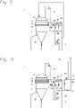
figure 9 est un schéma d'une première variante du procédé de l'invention, - la
figure 10 est un schéma d'une deuxième variante du procédé de l'invention, - la
figure 11 est un schéma d'une troisième variante du procédé de l'invention, - la
figure 12 est un schéma d'une quatrième variante du procédé de l'invention.
- the
figure 1 is a perspective of a double star filter according to the invention, without its cover, - the
picture 2 - the
picture 3 - the
figure 4 is a top view of the double star filter according to the invention of thefigure 1 , without its cover, - the
figure 5a is a top view of a simple star filter according to the invention, without its cover, - the
figure 5b is a top view of a filter according to the invention, the plates of which are arranged in parallel, without its cover, - the
figure 6a is a detail in perspective of single trays and double trays, and their connection duct according to the embodiment of thefigure 1 , - the
figure 6b is a section of a tray of thefigure 6a according to plan A - the
figure 7 is a section showing the detail of the connection between the tubing of a filter plate and a connection duct of thefigure 6a , - the
figure 8a is a developed schematic cross-section of four adjacent trays built simultaneously according to a state-of-the-art process, - the
figure 8b is a developed schematic section of four plates, two of which, not adjacent, built according to the method of the invention, - the
figure 9 is a diagram of a first variant of the method of the invention, - the
figure 10 is a diagram of a second variant of the method of the invention, - the
figure 11 is a diagram of a third variant of the process of the invention, - the
figure 12 is a diagram of a fourth variant of the method of the invention.
Dans la suite de la description, on considèrera que le haut correspond aux hauts des
Un filtre 1 de l'état de la technique, illustré
Les filtres 1 de petit diamètre de l'état de la technique, illustrés
Les filtres 1 de grand diamètre de l'état de la technique, illustrés
Le filtre 1 de la
Dans cet exemple, le nombre N de collecteurs extérieurs 5 est de trois. Pour N collecteurs extérieurs 5, N étant supérieur ou égal à trois, on aurait N groupes indépendants de plateaux 2 reliés chacun à un des N collecteurs extérieurs 5.In this example, the number N of
Ainsi comme on peut le voir
Dans cet exemple, le nombre N de collecteurs extérieurs 5 est de trois, et le plateau simple 20 et le plateau double 21 d'une même paire sont espacés de deux plateaux 2. Pour N collecteurs extérieurs 5, N étant supérieur ou égal à trois, le plateau simple 20 et le plateau double 21 d'une même paire seront espacés de deux ou d'un autre nombre pair de plateaux 2.In this example, the number N of
On peut voir
Le filtre 1 de la
Le filtre 1 de la
Dans l'état de la technique, le cycle de filtration du filtre 1 se décompose en deux phases : la phase de filtration et la phase de débâtissage. Pendant la phase de filtration, la cuve 3 du filtre 1 est remplie de la suspension à filtrer. Ladite cuve 3 est ensuite mise sous pression tandis que les plateaux 2, par l'intermédiaire de leur tubulure 200, sont mis en dépression. La phase liquide de la suspension passe alors au travers des toiles 221 des éléments filtrants 22, et la phase solide reste à la surface desdites toiles 221, formant un gâteau 6. Pendant la phase de filtration, les toiles 221 sont plaquées sur les drains 220 de l'élément filtrant 22. La phase de filtration s'arrête quand la résistance des gâteaux 6 à l'écoulement du liquide devient trop importante. Il faut alors détacher les gâteaux 6 des toiles 221, c'est la phase de débâtissage. Plusieurs procédés de débâtissage permettent de détacher les gâteaux 6 des éléments filtrants 22, mais il s'agit souvent, comme on peut le voir
Le procédé de débâtissage le plus courant est le débâtissage par contre-courant de filtrat. Le plus souvent, le filtrat utilisé est stocké pendant la phase de filtration dans un ballon, dit "ballon de soufflage", situé au-dessus du filtre 1. Pendant la phase de débâtissage, ledit filtrat est renvoyé sous le seul effet de la gravité dans tous les éléments filtrants 22 du filtre 1, après mise à l'atmosphère de la cuve 3 dudit filtre 1. Une fois détachés de leur élément filtrant 22, les gâteaux 6 décantent au sein de la suspension entre les plateaux 2, jusqu'au fond du filtre 1, avant d'être extraits.The most common deconstruction process is countercurrent filtrate deconstruction. Most often, the filtrate used is stored during the filtration phase in a balloon, called "blowing balloon", located above the
On voit
Typiquement, la distance minimum E1 entre les axes verticaux de deux éléments filtrants 22 adjacents du filtre 1 de l'état de la technique correspond à la somme de :
- la distance maximum de gonflement e1 séparant l'axe vertical d'un premier élément filtrant 22
et sa toile 221 gonflée par le filtrat, - la distance de détachement e2 du gâteau 6 dudit
premier élément filtrant 22, - l'épaisseur maximum autorisée
e3 dudit gâteau 6, - la distance maximum de gonflement e1 séparant l'axe vertical du deuxième élément filtrant 22
et sa toile 221 gonflée par le filtrat, - la distance de détachement e2 du gâteau 6 dudit deuxième élément filtrant 22,
- l'épaisseur maximum autorisée
e3 dudit gâteau 6, - une distance de sécurité
e4 entre gâteaux 6 débâtis se faisant face.
- the maximum inflation distance e1 separating the vertical axis of a
first filtering element 22 and itsfabric 221 inflated by the filtrate, - the detachment distance e2 of the
cake 6 of saidfirst filter element 22, - the maximum authorized thickness e3 of said
cake 6, - the maximum inflation distance e1 separating the vertical axis of the
second filtering element 22 and itsfabric 221 inflated by the filtrate, - the detachment distance e2 of the
cake 6 of saidsecond filter element 22, - the maximum authorized thickness e3 of said
cake 6, - a safety distance e4 between
cakes 6 facing each other.
On aura par exemple une distance minimum E1 entre les axes verticaux de deux éléments filtrants 22 adjacents de 124 mm, pour une distance maximum de gonflement e1 de 25 mm, pour une distance de détachement e2 de 10 mm, pour une épaisseur maximum autorisée e3 de 25 mm et pour une distance de sécurité e4 de 4 mm.For example, there will be a minimum distance E1 between the vertical axes of two
On voit
Cette distance de sécurité e5 est calculée par la formule suivante: ![]()
- h est la hauteur des éléments filtrants 22,
- Vf est la vitesse du courant de suspension pénétrant le gâteau 6 en cours de formation,
- Vd est la vitesse de décantation du gâteau 6 dans la suspension.
- h is the height of the
filter elements 22, - Vf is the speed of the suspension current penetrating the
cake 6 being formed, - Vd is the settling rate of
cake 6 in suspension.
La distance minimum E2 entre les axes verticaux de deux éléments filtrants 22 adjacents du filtre 1 de l'invention correspond à la somme de :
- la distance maximum de gonflement e1 séparant l'axe vertical d'un premier élément filtrant 22
et sa toile 221 gonflée par le filtrat, - la distance de détachement e2 du gâteau 6 dudit
premier élément filtrant 22, - l'épaisseur maximum autorisée
e3 dudit gâteau 6, - la distance maximum e6 séparant l'axe vertical du deuxième élément filtrant 22
et sa toile 221 appliquéeaudit élément filtrant 22, - l'épaisseur e7 du gâteau 6 en cours de formation,
- la distance de sécurité e5.

- the maximum inflation distance e1 separating the vertical axis of a
first filtering element 22 and itsfabric 221 inflated by the filtrate, - the detachment distance e2 of the
cake 6 of saidfirst filter element 22, - the maximum authorized thickness e3 of said
cake 6, - the maximum distance e6 separating the vertical axis of the
second filter element 22 and itsfabric 221 applied to saidfilter element 22, - the thickness e7 of the
cake 6 being formed, - the safety distance e5.
Dans le cas d'un filtre 1 de l'invention à deux collecteurs extérieurs, on aura par exemple une distance minimum E2 entre les axes verticaux de deux éléments filtrants 22 adjacents de 96 mm pour une distance maximum de gonflement e1 de 25 mm, pour une distance de détachement e2 de 10 mm, pour une épaisseur maximum autorisée e3 de 25 mm, pour une hauteur h de 3000 mm, pour une vitesse du courant de suspension Vf de 0,8 mm/s, pour une vitesse de décantation Vd de 200 mm/s, pour une distance maximum e6 de 6 mm et pour une épaisseur maximum autorisée e7 de 18 mm. E2 est donc inférieur à E1 de plus de 20%.In the case of a
L'exemple ci-dessus montre que pour un filtre 1 de l'invention, la distance minimum entre les axes verticaux de deux éléments filtrants 22 adjacents est réduite par rapport à ladite distance minimum pour un filtre 1 de l'état de la technique. Il est donc possible dans un filtre 1 de l'invention, de rapprocher les plateaux 2, d'augmenter le nombre desdits plateaux 2 et de maximiser ainsi la surface filtrante dudit filtre 1.The above example shows that for a
Le schéma représenté
Pendant la phase de filtration du groupe indépendant de plateaux 2 qui lui est connecté, chacun des trois collecteurs extérieurs 50, 51, 52 est en communication avec le conduit général 8 de filtrat au travers d'une vanne automatique 720, 721, 722. Pendant la phase de débâtissage du groupe indépendant de plateaux 2 qui lui est connecté, celui des trois collecteurs extérieurs 50, 51, 52 concerné est en communication avec le refoulement de la pompe 7 au travers d'une vanne automatique 730, 731, 732. Si la pression de refoulement de la pompe 7 était telle que la différence maximum autorisée entre la pression à l'intérieur des éléments filtrants 22 et la pression à l'extérieur des éléments filtrants 22 était atteinte, tout risque de dépassement serait évité grâce au déversement du fluide de soufflage excédentaire dans la cuve 3 du filtre 1 par le déversoir 70.During the filtration phase of the independent group of
Le schéma représenté
Pendant la phase de filtration du groupe indépendant de plateaux 2 qui lui est connecté, chacun des trois collecteurs extérieurs 50, 51, 52 est en communication avec le conduit général 8 de filtrat au travers d'une vanne automatique 720, 721, 722. Avant d'entamer la phase de débâtissage du groupe indépendant de plateaux 2 qui lui est connecté, celui des trois collecteurs extérieurs 50, 51, 52 concerné est mis en communication avec le ballon sur pressurisé 75 au travers d'une vanne automatique 730, 731, 732. Le ballon sur pressurisé 75 se remplit de filtrat, vanne automatique d'évent 751 ouverte et vanne automatique d'isolement 752 fermée. Quand le contact de niveau LS est atteint, la vanne automatique d'évent 751 se ferme et la vanne automatique d'isolement 752 s'ouvre pour permettre la régulation de la différence entre la pression à l'intérieur des éléments filtrants 22 et la pression à l'extérieur des éléments filtrants 22, entamant ainsi la phase de débâtissage. Si la pression d'air comprimé venant du régulateur automoteur de pression différentielle d'air comprimé 74 était telle que la différence maximum autorisée entre la pression à l'intérieur des éléments filtrants 22 et la pression à l'extérieur des éléments filtrants 22 était atteinte, tout risque de dépassement serait évité grâce au déversement du fluide de soufflage excédentaire dans la cuve 3 du filtre 1 par le déversoir 70.During the filtration phase of the independent group of
Le schéma représenté
Pendant la phase de filtration du groupe indépendant de plateaux 2 qui lui est connecté, chacun des trois collecteurs extérieurs 50, 51, 52 est en communication avec le conduit général 8 de filtrat au travers d'une vanne automatique 720, 721, 722. . Avant d'entamer la phase de débâtissage du groupe indépendant de plateaux 2 qui lui est connecté, celui des trois collecteurs extérieurs 50, 51, 52 concerné est mis en communication avec le ballon 76 au travers d'une vanne automatique 730, 731, 732. Le ballon 76 se remplit de filtrat, vanne automatique d'évent 78 ouverte et vanne automatique d'équilibrage 77 fermée. Quand le contact de niveau LS est atteint, la vanne automatique d'évent 78 se ferme et la vanne automatique d'équilibrage 77 s'ouvre pour équilibrer la pression au sommet du filtre 1 et la pression au sommet du ballon 76, entamant ainsi la phase de débâtissage. Durant cette phase, le ballon envoie le filtrat, sous le seul effet de la gravité, dans le collecteur extérieur 50, 51, 52 concerné. Le niveau de suspension dans le filtre 1, mesuré sur le transmetteur de niveau LT, augmente. Un niveau de suspension de consigne dans le filtre 1 est rétabli après chaque phase de débâtissage par ajout d'air comprimé au sommet du filtre 1 à travers la vanne automatique 9. La hauteur du ballon 76 est prévue pour que la différence maximum autorisée entre la pression à l'intérieur des éléments filtrants 22 et la pression à l'extérieur des éléments filtrants 22 ne soit jamais dépassée.During the filtration phase of the independent group of
Le schéma représenté
Pendant la phase de filtration du groupe indépendant de plateaux 2 qui lui est connecté, chacun des trois collecteurs extérieurs 50, 51, 52 est en communication avec le conduit général 8 de filtrat au travers d'un ballon 760, 761, 762 qui lui est propre, du trop-plein 7600, 7610, 7620 dudit ballon 761, 762, 763 et de la vanne de sortie de filtrat 790, 791, 792 dudit ballon 761, 762, 763. Avant d'entamer la phase de débâtissage du groupe indépendant de plateaux 2 qui lui est connecté, celui des trois collecteurs extérieurs 50, 51, 52 concerné est en communication directe avec son ballon 760, 761, 762. La vanne automatique d'évent 780, 781, 782 et la vanne automatique de sortie de filtrat dudit ballon 760, 761, 762 se ferment et la vanne automatique d'équilibrage 770, 771, 772 dudit ballon 760, 761, 762 s'ouvre pour équilibrer la pression au sommet du filtre 1 et la pression au sommet dudit ballon 760, 761, 762, entamant ainsi la phase de débâtissage. Durant cette phase, le ballon 760, 761, 762 envoie le filtrat, sous le seul effet de la gravité, dans le collecteur extérieur 50, 51, 52 concerné. Le niveau de suspension dans le filtre 1, mesuré sur le transmetteur de niveau LT, augmente. Un niveau de suspension de consigne dans le filtre 1 est rétabli après chaque phase de débâtissage par ajout d'air comprimé au sommet du filtre 1 à travers la vanne automatique 9. La hauteur des ballons 760, 761, 762 est prévue pour que la différence maximum autorisée entre la pression à l'intérieur des éléments filtrants 22 et la pression à l'extérieur des éléments filtrants 22 ne soit jamais dépassée.During the filtration phase of the independent group of
Claims (16)
- Filter (1) with vertical plates (2) comprising a tank (3), in which the plates (2) are suspended vertically inside the tank (3), each plate (2) comprising a tube (200) connected to a collector (5, 50, 51, 52) outside the tank (3) for the discharge of the filtrate, said filter is characterized in that it comprises N external collectors (5, 50, 51, 52), N being greater than or equal to 2, that for all the plates (2), two adjacent plates (2) are connected to two different external collectors (5, 50, 51, 52) in such a way that the plates (2) connected to the same external collector (5, 50, 51, 52) thus form an independent group of non-adjacent plates (2) whose plates (2) can be discharged simultaneously, each discharged cake (6) facing a cake (6) being formed the filter (1) comprising N independent groups of plates (2) which can be discharged by establishing a counter-blowing current alternately in each of the N external collectors (5, 50, 51, 52), and that each plate (2) comprises at least one filtering element (22), each filtering element (22) being constituted by at least two drains (220) and a cloth (221), the cloth (221) having compartments (222) in each of which a drain (220) is inserted in a way that during the filtration phase, the cloth (221) is pressed against the drains (220) and, during the blowing phase, the cloth (221) swells and moves away from the drains (220), the compartments (222) being designed in such a way that their narrowness allows the cloth (221) to swell slightly in order to allow the filter elements (22) to be brought closer to one another
- Filter (1) according to the preceding claim, characterized in that the plates (2) are arranged in a star shape.
- Filter (1) according to the preceding claim characterized in that each external collector (5) goes around the filter (1).
- Filter (1) according to claim 2 or 3, characterized in that it comprises an alternation of double plates (21) with two filtering elements (22) comprising a long tube (200) and single plates (20) with one filtering element (22) comprising a short tube (200), in that each single plate (20) is connected to a double plate (21), thus forming pairs of plates (2), in that the single plates (20) are accommodated on the inner periphery of the tank (3) in the space left free by the double plates (21).
- Filter (1) according to the preceding claim, characterized in that the short tube (200) of a single plate (20) is connected to the long tube (200) of a double plate (21) by a conduit (23) connecting the two plates (2).
- Filter (1) according to one of claims 4 or 5, characterized in that each pair of plates (2) is connected to one and only one external collector (5, 50, 51, 52) through the tubing of the double plate (21).
- Filter (1) according to any of claims 3 to 6, characterized in that N is greater than or equal to three.
- Filter (1) according to the preceding claim, characterized in that for all pairs of plates (2), N consecutive pairs of plates (2) are connected to the N outer collectors (5, 50, 51, 52), and in that the single plate (20) and the double plate (21) of the same pair are spaced by an even number of plates (2).
- A method of discharging cakes (6) of a filter (1) according to any of the preceding claims, characterized in that each external collector (5, 50, 51, 52) is traversed by a filtrate flow which reverses according to a predefined cycle, and in that the cycles of all the external collectors are identical and out of phase with each other, in that in each discharging phase, only the plates (2) of an independent group of non-adjacent plates (2) connected to a single external collector (5, 50, 51, 52) by causing the cloth (221) of each compartment (222) to swell so that it moves away from the drains (220), the other plates (2) remaining in the filtration phase during which the cloth (221) of each compartment (222) is pressed against the drains (220), thus ensuring continuity of the extraction of the filtrate, so as never to discharge two adjacent plates (2) at the same time.
- Method according to the preceding claim, characterized in that the cycles of reversing the filtrate flows of all the external collectors (5, 50, 51, 52) are out of phase by the same time interval.
- Method according to one of claims 9 or 10, characterized in that the flow of filtrate is reversed by means of a pump (7), through a blowing circuit able to put the discharge of said pump (7) in communication with each of the external collectors (5, 50, 51, 52).
- Method according to one of claims 9 or 10, characterized in that the flow of filtrate is reversed by means of an over pressurized balloon (75) filled with said filtrate, through a blowing circuit able to put the outlet of said over pressurized balloon (75) in communication with each of the external collectors (5, 50, 51, 52).
- Method according to one of claims 11 or 12, characterized in that the blower circuit is equipped in parallel with a safety overflow (70) between 1 and 5 m inclusive high above the filter (1) and connected to the interior of the filter (1) in the upper part of the tank (3) of said filter (1).
- Method according to one of claims 9 or 10, characterized in that the inversion of the filtrate flow is carried out by means of a balloon (76) filled with said filtrate, loaded on the filter (1) and connected to the tank (3) of said filter (1) in their upper part, said inversion being carried out through a blowing circuit able to put the outlet of said balloon (76) in communication with each of the external collectors (5, 50, 51, 52).
- Method according to one of claims 9 or 10, characterized in that the inversion of the filtrate flow is carried out by means of balloons (760, 761, 762) filled with the said filtrate, loaded on the filter (1) and connected to the tank (3) of the said filter (1) at their upper part, said inversion being effected through blowing circuits each of which can put the outlet of one and only one of said tanks (760, 761, 762) in communication with one and only one of the external collectors (5, 50, 51, 52).
- A method according to one of claims 14 or 15, characterized in that the upper part of the balloons (76, 760, 761, 762) is located between 1 and 5 m above the filter (1).
Applications Claiming Priority (2)
| Application Number | Priority Date | Filing Date | Title |
|---|---|---|---|
| PCT/FR2016/052797 WO2018078223A1 (en) | 2016-10-27 | 2016-10-27 | Filter with closely-spaced vertical plates |
| PCT/FR2017/052963 WO2018078294A1 (en) | 2016-10-27 | 2017-10-26 | Filter with closely-spaced vertical plates |
Publications (2)
| Publication Number | Publication Date |
|---|---|
| EP3532184A1 EP3532184A1 (en) | 2019-09-04 |
| EP3532184B1 true EP3532184B1 (en) | 2022-06-22 |
Family
ID=57543064
Family Applications (1)
| Application Number | Title | Priority Date | Filing Date |
|---|---|---|---|
| EP17801073.2A Active EP3532184B1 (en) | 2016-10-27 | 2017-10-26 | Dense vertical leaf filter |
Country Status (10)
| Country | Link |
|---|---|
| US (1) | US11173430B2 (en) |
| EP (1) | EP3532184B1 (en) |
| CN (1) | CN109937079B (en) |
| AU (1) | AU2017349329B2 (en) |
| BR (1) | BR112019008573B1 (en) |
| CA (1) | CA3041755A1 (en) |
| EA (1) | EA038713B1 (en) |
| ES (1) | ES2926470T3 (en) |
| PL (1) | PL3532184T3 (en) |
| WO (2) | WO2018078223A1 (en) |
Families Citing this family (4)
| Publication number | Priority date | Publication date | Assignee | Title |
|---|---|---|---|---|
| WO2019241248A1 (en) * | 2018-06-13 | 2019-12-19 | Cargill, Incorporated | Liquid discharge filter and its use |
| CN110548327B (en) * | 2019-09-27 | 2022-05-10 | 杭州科百特过滤器材有限公司 | Dish-shaped filter disc for filtering high-viscosity melt |
| CN112023505A (en) * | 2020-08-11 | 2020-12-04 | 孙悦 | Cleaning device for wastewater treatment pool for rare earth oxide production and implementation method thereof |
| CN113813658B (en) * | 2021-08-04 | 2022-08-26 | 长沙市市政工程有限责任公司 | Slurry filter press for bridge pile foundation construction |
Family Cites Families (14)
| Publication number | Priority date | Publication date | Assignee | Title |
|---|---|---|---|---|
| GB270616A (en) * | 1926-06-11 | 1927-05-12 | Oliver Continuous Filter Compa | Improvements in and connected with pulp thickeners or filters |
| DE1082575B (en) * | 1958-06-25 | 1960-06-02 | Krauss Maffei Imp G M B H & Co | Pipe thickener for thickening mass suspensions |
| US2974748A (en) * | 1959-12-16 | 1961-03-14 | Day Company | Air filter |
| FR1425376A (en) * | 1964-12-02 | 1966-01-24 | Fives Lille Cail | Continuous thickening filter |
| GB2094653A (en) * | 1981-03-13 | 1982-09-22 | Johnson Willard Lewis | Alternately operated sets of filters in filter tank |
| DE3340952C2 (en) * | 1983-11-11 | 1994-12-01 | Sanshin Mfg Co Ltd | Filter unit |
| FR2588765B1 (en) * | 1985-10-17 | 1988-01-15 | Gaudfrin Guy | FILTER FOR LIQUIDS FILLED WITH SOLID PARTICLES AND FILTRATION SYSTEM COMPRISING SUCH A FILTER |
| US4790935A (en) * | 1986-11-26 | 1988-12-13 | Johnson Willard L | Filter leaf assembly with bonded spacer and sealer |
| US4861498A (en) * | 1987-12-30 | 1989-08-29 | R & L Filtration Limited | Backwash system for filter-thickeners |
| DE19734588A1 (en) * | 1997-08-09 | 1999-02-11 | Boll & Kirch Filter | Backwashing filter |
| US7754078B2 (en) * | 2004-09-23 | 2010-07-13 | Guy Gaudfrin | Filtering element for liquids filtering installation comprising same |
| CN103100251A (en) * | 2006-05-02 | 2013-05-15 | 比吉尔·尼尔森 | Device and method for separating and filtering grains and organic matters from large-flow flowing liquid |
| CN201921580U (en) * | 2010-09-14 | 2011-08-10 | 高敏 | Filter device of leaf filter |
| CN105817063A (en) * | 2016-01-08 | 2016-08-03 | 南通航泰船舶机械有限公司 | System differential-pressure driven back-flush filter |
-
2016
- 2016-10-27 WO PCT/FR2016/052797 patent/WO2018078223A1/en active Application Filing
-
2017
- 2017-10-26 US US16/345,944 patent/US11173430B2/en active Active
- 2017-10-26 WO PCT/FR2017/052963 patent/WO2018078294A1/en unknown
- 2017-10-26 CN CN201780069358.1A patent/CN109937079B/en active Active
- 2017-10-26 CA CA3041755A patent/CA3041755A1/en active Pending
- 2017-10-26 ES ES17801073T patent/ES2926470T3/en active Active
- 2017-10-26 BR BR112019008573-4A patent/BR112019008573B1/en active IP Right Grant
- 2017-10-26 EA EA201990786A patent/EA038713B1/en unknown
- 2017-10-26 PL PL17801073.2T patent/PL3532184T3/en unknown
- 2017-10-26 EP EP17801073.2A patent/EP3532184B1/en active Active
- 2017-10-26 AU AU2017349329A patent/AU2017349329B2/en active Active
Also Published As
| Publication number | Publication date |
|---|---|
| WO2018078294A1 (en) | 2018-05-03 |
| AU2017349329A1 (en) | 2019-06-13 |
| AU2017349329B2 (en) | 2020-01-30 |
| CA3041755A1 (en) | 2018-05-03 |
| EA201990786A1 (en) | 2019-11-29 |
| CN109937079A (en) | 2019-06-25 |
| US11173430B2 (en) | 2021-11-16 |
| CN109937079B (en) | 2021-12-07 |
| EP3532184A1 (en) | 2019-09-04 |
| US20190329163A1 (en) | 2019-10-31 |
| EA038713B1 (en) | 2021-10-08 |
| ES2926470T3 (en) | 2022-10-26 |
| BR112019008573A2 (en) | 2019-07-09 |
| PL3532184T3 (en) | 2022-11-28 |
| WO2018078223A1 (en) | 2018-05-03 |
| BR112019008573B1 (en) | 2023-03-07 |
Similar Documents
| Publication | Publication Date | Title |
|---|---|---|
| EP3532184B1 (en) | Dense vertical leaf filter | |
| CA1325181C (en) | Nonmiscible liquids separator | |
| EP2585188B1 (en) | Modular device for liquid/liquid gravity separation | |
| EP0226478B1 (en) | Filter for liquids containing solid particles, and filter apparatus containing said filter | |
| EP2897716A1 (en) | Underwater water treatment unit and method for cleaning said unit | |
| WO2012146730A1 (en) | Device for extracting solid material on the bed of a body of water, and associated method | |
| EP0120750B1 (en) | Device for tangential filtration and installation containing this device | |
| EP2705132A1 (en) | Method for harvesting microalgae, and device for implementing said method | |
| CN205164515U (en) | Membrane module | |
| EP3138620B1 (en) | Filtration method in a membrane filter press | |
| CA2338174C (en) | Method and device for membrane filtering of water | |
| WO2018096296A1 (en) | System for filtering a solution comprising microalgae for the harvesting thereof | |
| EP0147320A2 (en) | Degassing apparatus | |
| EP2164808B1 (en) | Autonomous sea water purification device having alternating submerged filtration modules with multipiston low-pressure chambers | |
| EP2889069B1 (en) | Filter for free-flowing liquid | |
| US1334692A (en) | Bag-filter | |
| JP5944195B2 (en) | Ballast water membrane treatment method and membrane treatment method | |
| JP2018183730A (en) | Reverse osmosis membrane filtration device and method for cleaning reverse osmosis membrane | |
| CN110613957A (en) | Three-phase separator system | |
| EP1484095A2 (en) | Settler for the treatment of waste effluents | |
| EP3471900A1 (en) | Wine press and method for cleaning the vat of such a press | |
| FR3011544A1 (en) | DEVICE AND METHOD FOR SLUDGE THICKENING | |
| BE540923A (en) | ||
| CH106207A (en) | Process for filtering liquids containing suspended solids and installation for implementing this process. | |
| BE332667A (en) |
Legal Events
| Date | Code | Title | Description |
|---|---|---|---|
| STAA | Information on the status of an ep patent application or granted ep patent |
Free format text: STATUS: UNKNOWN |
|
| STAA | Information on the status of an ep patent application or granted ep patent |
Free format text: STATUS: THE INTERNATIONAL PUBLICATION HAS BEEN MADE |
|
| PUAI | Public reference made under article 153(3) epc to a published international application that has entered the european phase |
Free format text: ORIGINAL CODE: 0009012 |
|
| STAA | Information on the status of an ep patent application or granted ep patent |
Free format text: STATUS: REQUEST FOR EXAMINATION WAS MADE |
|
| 17P | Request for examination filed |
Effective date: 20190520 |
|
| AK | Designated contracting states |
Kind code of ref document: A1 Designated state(s): AL AT BE BG CH CY CZ DE DK EE ES FI FR GB GR HR HU IE IS IT LI LT LU LV MC MK MT NL NO PL PT RO RS SE SI SK SM TR |
|
| AX | Request for extension of the european patent |
Extension state: BA ME |
|
| DAV | Request for validation of the european patent (deleted) | ||
| DAX | Request for extension of the european patent (deleted) | ||
| STAA | Information on the status of an ep patent application or granted ep patent |
Free format text: STATUS: EXAMINATION IS IN PROGRESS |
|
| 17Q | First examination report despatched |
Effective date: 20200515 |
|
| STAA | Information on the status of an ep patent application or granted ep patent |
Free format text: STATUS: EXAMINATION IS IN PROGRESS |
|
| STAA | Information on the status of an ep patent application or granted ep patent |
Free format text: STATUS: EXAMINATION IS IN PROGRESS |
|
| GRAP | Despatch of communication of intention to grant a patent |
Free format text: ORIGINAL CODE: EPIDOSNIGR1 |
|
| STAA | Information on the status of an ep patent application or granted ep patent |
Free format text: STATUS: GRANT OF PATENT IS INTENDED |
|
| RAP3 | Party data changed (applicant data changed or rights of an application transferred) |
Owner name: GAUDFRIN |
|
| RIN1 | Information on inventor provided before grant (corrected) |
Inventor name: GAUDFRIN, GUY |
|
| INTG | Intention to grant announced |
Effective date: 20220131 |
|
| GRAS | Grant fee paid |
Free format text: ORIGINAL CODE: EPIDOSNIGR3 |
|
| GRAA | (expected) grant |
Free format text: ORIGINAL CODE: 0009210 |
|
| STAA | Information on the status of an ep patent application or granted ep patent |
Free format text: STATUS: THE PATENT HAS BEEN GRANTED |
|
| AK | Designated contracting states |
Kind code of ref document: B1 Designated state(s): AL AT BE BG CH CY CZ DE DK EE ES FI FR GB GR HR HU IE IS IT LI LT LU LV MC MK MT NL NO PL PT RO RS SE SI SK SM TR |
|
| REG | Reference to a national code |
Ref country code: GB Ref legal event code: FG4D Free format text: NOT ENGLISH |
|
| REG | Reference to a national code |
Ref country code: CH Ref legal event code: EP |
|
| REG | Reference to a national code |
Ref country code: DE Ref legal event code: R096 Ref document number: 602017058800 Country of ref document: DE |
|
| REG | Reference to a national code |
Ref country code: AT Ref legal event code: REF Ref document number: 1499394 Country of ref document: AT Kind code of ref document: T Effective date: 20220715 |
|
| REG | Reference to a national code |
Ref country code: IE Ref legal event code: FG4D Free format text: LANGUAGE OF EP DOCUMENT: FRENCH |
|
| REG | Reference to a national code |
Ref country code: SE Ref legal event code: TRGR |
|
| REG | Reference to a national code |
Ref country code: LT Ref legal event code: MG9D |
|
| REG | Reference to a national code |
Ref country code: NL Ref legal event code: MP Effective date: 20220622 Ref country code: ES Ref legal event code: FG2A Ref document number: 2926470 Country of ref document: ES Kind code of ref document: T3 Effective date: 20221026 Ref country code: GR Ref legal event code: EP Ref document number: 20220401790 Country of ref document: GR Effective date: 20221010 |
|
| PG25 | Lapsed in a contracting state [announced via postgrant information from national office to epo] |
Ref country code: NO Free format text: LAPSE BECAUSE OF FAILURE TO SUBMIT A TRANSLATION OF THE DESCRIPTION OR TO PAY THE FEE WITHIN THE PRESCRIBED TIME-LIMIT Effective date: 20220922 Ref country code: LT Free format text: LAPSE BECAUSE OF FAILURE TO SUBMIT A TRANSLATION OF THE DESCRIPTION OR TO PAY THE FEE WITHIN THE PRESCRIBED TIME-LIMIT Effective date: 20220622 Ref country code: HR Free format text: LAPSE BECAUSE OF FAILURE TO SUBMIT A TRANSLATION OF THE DESCRIPTION OR TO PAY THE FEE WITHIN THE PRESCRIBED TIME-LIMIT Effective date: 20220622 Ref country code: FI Free format text: LAPSE BECAUSE OF FAILURE TO SUBMIT A TRANSLATION OF THE DESCRIPTION OR TO PAY THE FEE WITHIN THE PRESCRIBED TIME-LIMIT Effective date: 20220622 Ref country code: BG Free format text: LAPSE BECAUSE OF FAILURE TO SUBMIT A TRANSLATION OF THE DESCRIPTION OR TO PAY THE FEE WITHIN THE PRESCRIBED TIME-LIMIT Effective date: 20220922 |
|
| PG25 | Lapsed in a contracting state [announced via postgrant information from national office to epo] |
Ref country code: RS Free format text: LAPSE BECAUSE OF FAILURE TO SUBMIT A TRANSLATION OF THE DESCRIPTION OR TO PAY THE FEE WITHIN THE PRESCRIBED TIME-LIMIT Effective date: 20220622 Ref country code: LV Free format text: LAPSE BECAUSE OF FAILURE TO SUBMIT A TRANSLATION OF THE DESCRIPTION OR TO PAY THE FEE WITHIN THE PRESCRIBED TIME-LIMIT Effective date: 20220622 |
|
| PG25 | Lapsed in a contracting state [announced via postgrant information from national office to epo] |
Ref country code: NL Free format text: LAPSE BECAUSE OF FAILURE TO SUBMIT A TRANSLATION OF THE DESCRIPTION OR TO PAY THE FEE WITHIN THE PRESCRIBED TIME-LIMIT Effective date: 20220622 |
|
| PG25 | Lapsed in a contracting state [announced via postgrant information from national office to epo] |
Ref country code: SM Free format text: LAPSE BECAUSE OF FAILURE TO SUBMIT A TRANSLATION OF THE DESCRIPTION OR TO PAY THE FEE WITHIN THE PRESCRIBED TIME-LIMIT Effective date: 20220622 Ref country code: SK Free format text: LAPSE BECAUSE OF FAILURE TO SUBMIT A TRANSLATION OF THE DESCRIPTION OR TO PAY THE FEE WITHIN THE PRESCRIBED TIME-LIMIT Effective date: 20220622 Ref country code: RO Free format text: LAPSE BECAUSE OF FAILURE TO SUBMIT A TRANSLATION OF THE DESCRIPTION OR TO PAY THE FEE WITHIN THE PRESCRIBED TIME-LIMIT Effective date: 20220622 Ref country code: PT Free format text: LAPSE BECAUSE OF FAILURE TO SUBMIT A TRANSLATION OF THE DESCRIPTION OR TO PAY THE FEE WITHIN THE PRESCRIBED TIME-LIMIT Effective date: 20221024 Ref country code: EE Free format text: LAPSE BECAUSE OF FAILURE TO SUBMIT A TRANSLATION OF THE DESCRIPTION OR TO PAY THE FEE WITHIN THE PRESCRIBED TIME-LIMIT Effective date: 20220622 Ref country code: CZ Free format text: LAPSE BECAUSE OF FAILURE TO SUBMIT A TRANSLATION OF THE DESCRIPTION OR TO PAY THE FEE WITHIN THE PRESCRIBED TIME-LIMIT Effective date: 20220622 |
|
| PG25 | Lapsed in a contracting state [announced via postgrant information from national office to epo] |
Ref country code: IS Free format text: LAPSE BECAUSE OF FAILURE TO SUBMIT A TRANSLATION OF THE DESCRIPTION OR TO PAY THE FEE WITHIN THE PRESCRIBED TIME-LIMIT Effective date: 20221022 |
|
| REG | Reference to a national code |
Ref country code: DE Ref legal event code: R097 Ref document number: 602017058800 Country of ref document: DE |
|
| PG25 | Lapsed in a contracting state [announced via postgrant information from national office to epo] |
Ref country code: AL Free format text: LAPSE BECAUSE OF FAILURE TO SUBMIT A TRANSLATION OF THE DESCRIPTION OR TO PAY THE FEE WITHIN THE PRESCRIBED TIME-LIMIT Effective date: 20220622 |
|
| PG25 | Lapsed in a contracting state [announced via postgrant information from national office to epo] |
Ref country code: DK Free format text: LAPSE BECAUSE OF FAILURE TO SUBMIT A TRANSLATION OF THE DESCRIPTION OR TO PAY THE FEE WITHIN THE PRESCRIBED TIME-LIMIT Effective date: 20220622 |
|
| PLBE | No opposition filed within time limit |
Free format text: ORIGINAL CODE: 0009261 |
|
| STAA | Information on the status of an ep patent application or granted ep patent |
Free format text: STATUS: NO OPPOSITION FILED WITHIN TIME LIMIT |
|
| 26N | No opposition filed |
Effective date: 20230323 |
|
| PG25 | Lapsed in a contracting state [announced via postgrant information from national office to epo] |
Ref country code: MC Free format text: LAPSE BECAUSE OF FAILURE TO SUBMIT A TRANSLATION OF THE DESCRIPTION OR TO PAY THE FEE WITHIN THE PRESCRIBED TIME-LIMIT Effective date: 20220622 |
|
| REG | Reference to a national code |
Ref country code: CH Ref legal event code: PL |
|
| REG | Reference to a national code |
Ref country code: BE Ref legal event code: MM Effective date: 20221031 |
|
| GBPC | Gb: european patent ceased through non-payment of renewal fee |
Effective date: 20221026 |
|
| PG25 | Lapsed in a contracting state [announced via postgrant information from national office to epo] |
Ref country code: LU Free format text: LAPSE BECAUSE OF NON-PAYMENT OF DUE FEES Effective date: 20221026 |
|
| PG25 | Lapsed in a contracting state [announced via postgrant information from national office to epo] |
Ref country code: LI Free format text: LAPSE BECAUSE OF NON-PAYMENT OF DUE FEES Effective date: 20221031 Ref country code: CH Free format text: LAPSE BECAUSE OF NON-PAYMENT OF DUE FEES Effective date: 20221031 |
|
| REG | Reference to a national code |
Ref country code: AT Ref legal event code: UEP Ref document number: 1499394 Country of ref document: AT Kind code of ref document: T Effective date: 20220622 |
|
| PG25 | Lapsed in a contracting state [announced via postgrant information from national office to epo] |
Ref country code: SI Free format text: LAPSE BECAUSE OF FAILURE TO SUBMIT A TRANSLATION OF THE DESCRIPTION OR TO PAY THE FEE WITHIN THE PRESCRIBED TIME-LIMIT Effective date: 20220622 |
|
| PG25 | Lapsed in a contracting state [announced via postgrant information from national office to epo] |
Ref country code: BE Free format text: LAPSE BECAUSE OF NON-PAYMENT OF DUE FEES Effective date: 20221031 |
|
| PG25 | Lapsed in a contracting state [announced via postgrant information from national office to epo] |
Ref country code: IE Free format text: LAPSE BECAUSE OF NON-PAYMENT OF DUE FEES Effective date: 20221026 Ref country code: GB Free format text: LAPSE BECAUSE OF NON-PAYMENT OF DUE FEES Effective date: 20221026 |
|
| PGFP | Annual fee paid to national office [announced via postgrant information from national office to epo] |
Ref country code: GR Payment date: 20231019 Year of fee payment: 7 |
|
| PGFP | Annual fee paid to national office [announced via postgrant information from national office to epo] |
Ref country code: ES Payment date: 20231117 Year of fee payment: 7 |
|
| PGFP | Annual fee paid to national office [announced via postgrant information from national office to epo] |
Ref country code: SE Payment date: 20231025 Year of fee payment: 7 Ref country code: IT Payment date: 20231031 Year of fee payment: 7 Ref country code: FR Payment date: 20231023 Year of fee payment: 7 Ref country code: DE Payment date: 20231018 Year of fee payment: 7 Ref country code: AT Payment date: 20231019 Year of fee payment: 7 |
|
| PGFP | Annual fee paid to national office [announced via postgrant information from national office to epo] |
Ref country code: PL Payment date: 20231018 Year of fee payment: 7 |
|
| PG25 | Lapsed in a contracting state [announced via postgrant information from national office to epo] |
Ref country code: HU Free format text: LAPSE BECAUSE OF FAILURE TO SUBMIT A TRANSLATION OF THE DESCRIPTION OR TO PAY THE FEE WITHIN THE PRESCRIBED TIME-LIMIT; INVALID AB INITIO Effective date: 20171026 |
|
| PG25 | Lapsed in a contracting state [announced via postgrant information from national office to epo] |
Ref country code: CY Free format text: LAPSE BECAUSE OF FAILURE TO SUBMIT A TRANSLATION OF THE DESCRIPTION OR TO PAY THE FEE WITHIN THE PRESCRIBED TIME-LIMIT Effective date: 20220622 |