EP3532160B1 - Separate device in managing the pace pulse energy of a cardiac pacemaker - Google Patents
Separate device in managing the pace pulse energy of a cardiac pacemaker Download PDFInfo
- Publication number
- EP3532160B1 EP3532160B1 EP17794201.8A EP17794201A EP3532160B1 EP 3532160 B1 EP3532160 B1 EP 3532160B1 EP 17794201 A EP17794201 A EP 17794201A EP 3532160 B1 EP3532160 B1 EP 3532160B1
- Authority
- EP
- European Patent Office
- Prior art keywords
- pacing
- lcp
- medical device
- heart
- pacing pulses
- Prior art date
- Legal status (The legal status is an assumption and is not a legal conclusion. Google has not performed a legal analysis and makes no representation as to the accuracy of the status listed.)
- Active
Links
- 230000000747 cardiac effect Effects 0.000 title claims description 81
- 238000004891 communication Methods 0.000 claims description 71
- 230000000694 effects Effects 0.000 claims description 33
- 230000008859 change Effects 0.000 claims description 15
- 230000001105 regulatory effect Effects 0.000 claims description 9
- 230000004044 response Effects 0.000 claims description 7
- 230000035939 shock Effects 0.000 claims description 6
- 238000002560 therapeutic procedure Methods 0.000 description 27
- 238000012545 processing Methods 0.000 description 22
- 230000000638 stimulation Effects 0.000 description 22
- 238000010586 diagram Methods 0.000 description 19
- 238000000034 method Methods 0.000 description 15
- 210000005003 heart tissue Anatomy 0.000 description 12
- 230000001965 increasing effect Effects 0.000 description 12
- 210000005240 left ventricle Anatomy 0.000 description 11
- 230000003247 decreasing effect Effects 0.000 description 10
- 230000006870 function Effects 0.000 description 10
- 229920000106 Liquid crystal polymer Polymers 0.000 description 9
- 206010003119 arrhythmia Diseases 0.000 description 9
- 230000006793 arrhythmia Effects 0.000 description 8
- 239000008280 blood Substances 0.000 description 8
- 210000004369 blood Anatomy 0.000 description 8
- 238000003032 molecular docking Methods 0.000 description 8
- 238000007920 subcutaneous administration Methods 0.000 description 8
- 210000005241 right ventricle Anatomy 0.000 description 7
- 210000001519 tissue Anatomy 0.000 description 7
- 208000001871 Tachycardia Diseases 0.000 description 6
- 230000005856 abnormality Effects 0.000 description 6
- 238000009125 cardiac resynchronization therapy Methods 0.000 description 6
- 230000008867 communication pathway Effects 0.000 description 6
- 238000001514 detection method Methods 0.000 description 6
- 238000002513 implantation Methods 0.000 description 6
- 230000007246 mechanism Effects 0.000 description 6
- 230000014759 maintenance of location Effects 0.000 description 5
- 210000001562 sternum Anatomy 0.000 description 5
- 238000012795 verification Methods 0.000 description 5
- 230000036471 bradycardia Effects 0.000 description 4
- 208000006218 bradycardia Diseases 0.000 description 4
- 230000008602 contraction Effects 0.000 description 4
- 238000012544 monitoring process Methods 0.000 description 4
- 210000005245 right atrium Anatomy 0.000 description 4
- 230000036772 blood pressure Effects 0.000 description 3
- 239000003990 capacitor Substances 0.000 description 3
- 238000002847 impedance measurement Methods 0.000 description 3
- 230000001939 inductive effect Effects 0.000 description 3
- 210000005246 left atrium Anatomy 0.000 description 3
- 230000003287 optical effect Effects 0.000 description 3
- 230000000737 periodic effect Effects 0.000 description 3
- 239000000126 substance Substances 0.000 description 3
- 210000000115 thoracic cavity Anatomy 0.000 description 3
- 208000033986 Device capturing issue Diseases 0.000 description 2
- 230000009471 action Effects 0.000 description 2
- 238000004873 anchoring Methods 0.000 description 2
- 230000002051 biphasic effect Effects 0.000 description 2
- 206010061592 cardiac fibrillation Diseases 0.000 description 2
- 239000004020 conductor Substances 0.000 description 2
- 230000002596 correlated effect Effects 0.000 description 2
- 230000008878 coupling Effects 0.000 description 2
- 238000010168 coupling process Methods 0.000 description 2
- 238000005859 coupling reaction Methods 0.000 description 2
- 210000002837 heart atrium Anatomy 0.000 description 2
- 239000000463 material Substances 0.000 description 2
- 229910052760 oxygen Inorganic materials 0.000 description 2
- 239000001301 oxygen Substances 0.000 description 2
- 230000008569 process Effects 0.000 description 2
- 230000033764 rhythmic process Effects 0.000 description 2
- 230000006794 tachycardia Effects 0.000 description 2
- 238000012360 testing method Methods 0.000 description 2
- 239000013598 vector Substances 0.000 description 2
- 208000031229 Cardiomyopathies Diseases 0.000 description 1
- WHXSMMKQMYFTQS-UHFFFAOYSA-N Lithium Chemical compound [Li] WHXSMMKQMYFTQS-UHFFFAOYSA-N 0.000 description 1
- 206010049447 Tachyarrhythmia Diseases 0.000 description 1
- 230000001133 acceleration Effects 0.000 description 1
- 229910045601 alloy Inorganic materials 0.000 description 1
- 239000000956 alloy Substances 0.000 description 1
- 210000003484 anatomy Anatomy 0.000 description 1
- 230000003288 anthiarrhythmic effect Effects 0.000 description 1
- 239000003416 antiarrhythmic agent Substances 0.000 description 1
- 230000008901 benefit Effects 0.000 description 1
- 238000009530 blood pressure measurement Methods 0.000 description 1
- 210000005242 cardiac chamber Anatomy 0.000 description 1
- 238000013194 cardioversion Methods 0.000 description 1
- 210000000038 chest Anatomy 0.000 description 1
- 230000007812 deficiency Effects 0.000 description 1
- 238000013461 design Methods 0.000 description 1
- 201000010099 disease Diseases 0.000 description 1
- 208000037265 diseases, disorders, signs and symptoms Diseases 0.000 description 1
- 238000001827 electrotherapy Methods 0.000 description 1
- 238000005265 energy consumption Methods 0.000 description 1
- 230000002600 fibrillogenic effect Effects 0.000 description 1
- 239000012530 fluid Substances 0.000 description 1
- 238000002594 fluoroscopy Methods 0.000 description 1
- 230000010247 heart contraction Effects 0.000 description 1
- 239000007943 implant Substances 0.000 description 1
- 230000006872 improvement Effects 0.000 description 1
- 238000009413 insulation Methods 0.000 description 1
- 230000010354 integration Effects 0.000 description 1
- 230000001788 irregular Effects 0.000 description 1
- 229910052744 lithium Inorganic materials 0.000 description 1
- 230000007774 longterm Effects 0.000 description 1
- 229910052751 metal Inorganic materials 0.000 description 1
- 239000002184 metal Substances 0.000 description 1
- 150000002739 metals Chemical class 0.000 description 1
- 230000000877 morphologic effect Effects 0.000 description 1
- 210000000663 muscle cell Anatomy 0.000 description 1
- 230000002107 myocardial effect Effects 0.000 description 1
- 238000005457 optimization Methods 0.000 description 1
- 230000037361 pathway Effects 0.000 description 1
- 230000004962 physiological condition Effects 0.000 description 1
- 230000036279 refractory period Effects 0.000 description 1
- 238000004088 simulation Methods 0.000 description 1
- 230000002861 ventricular Effects 0.000 description 1
Images


Classifications
-
- A—HUMAN NECESSITIES
- A61—MEDICAL OR VETERINARY SCIENCE; HYGIENE
- A61N—ELECTROTHERAPY; MAGNETOTHERAPY; RADIATION THERAPY; ULTRASOUND THERAPY
- A61N1/00—Electrotherapy; Circuits therefor
- A61N1/18—Applying electric currents by contact electrodes
- A61N1/32—Applying electric currents by contact electrodes alternating or intermittent currents
- A61N1/36—Applying electric currents by contact electrodes alternating or intermittent currents for stimulation
- A61N1/3605—Implantable neurostimulators for stimulating central or peripheral nerve system
- A61N1/36128—Control systems
- A61N1/36146—Control systems specified by the stimulation parameters
-
- A—HUMAN NECESSITIES
- A61—MEDICAL OR VETERINARY SCIENCE; HYGIENE
- A61N—ELECTROTHERAPY; MAGNETOTHERAPY; RADIATION THERAPY; ULTRASOUND THERAPY
- A61N1/00—Electrotherapy; Circuits therefor
- A61N1/18—Applying electric currents by contact electrodes
- A61N1/32—Applying electric currents by contact electrodes alternating or intermittent currents
- A61N1/36—Applying electric currents by contact electrodes alternating or intermittent currents for stimulation
- A61N1/362—Heart stimulators
- A61N1/3621—Heart stimulators for treating or preventing abnormally high heart rate
- A61N1/3622—Heart stimulators for treating or preventing abnormally high heart rate comprising two or more electrodes co-operating with different heart regions
-
- A—HUMAN NECESSITIES
- A61—MEDICAL OR VETERINARY SCIENCE; HYGIENE
- A61N—ELECTROTHERAPY; MAGNETOTHERAPY; RADIATION THERAPY; ULTRASOUND THERAPY
- A61N1/00—Electrotherapy; Circuits therefor
- A61N1/18—Applying electric currents by contact electrodes
- A61N1/32—Applying electric currents by contact electrodes alternating or intermittent currents
- A61N1/36—Applying electric currents by contact electrodes alternating or intermittent currents for stimulation
- A61N1/362—Heart stimulators
- A61N1/365—Heart stimulators controlled by a physiological parameter, e.g. heart potential
- A61N1/36514—Heart stimulators controlled by a physiological parameter, e.g. heart potential controlled by a physiological quantity other than heart potential, e.g. blood pressure
- A61N1/36521—Heart stimulators controlled by a physiological parameter, e.g. heart potential controlled by a physiological quantity other than heart potential, e.g. blood pressure the parameter being derived from measurement of an electrical impedance
-
- A—HUMAN NECESSITIES
- A61—MEDICAL OR VETERINARY SCIENCE; HYGIENE
- A61N—ELECTROTHERAPY; MAGNETOTHERAPY; RADIATION THERAPY; ULTRASOUND THERAPY
- A61N1/00—Electrotherapy; Circuits therefor
- A61N1/18—Applying electric currents by contact electrodes
- A61N1/32—Applying electric currents by contact electrodes alternating or intermittent currents
- A61N1/36—Applying electric currents by contact electrodes alternating or intermittent currents for stimulation
- A61N1/362—Heart stimulators
- A61N1/37—Monitoring; Protecting
- A61N1/371—Capture, i.e. successful stimulation
-
- A—HUMAN NECESSITIES
- A61—MEDICAL OR VETERINARY SCIENCE; HYGIENE
- A61N—ELECTROTHERAPY; MAGNETOTHERAPY; RADIATION THERAPY; ULTRASOUND THERAPY
- A61N1/00—Electrotherapy; Circuits therefor
- A61N1/18—Applying electric currents by contact electrodes
- A61N1/32—Applying electric currents by contact electrodes alternating or intermittent currents
- A61N1/36—Applying electric currents by contact electrodes alternating or intermittent currents for stimulation
- A61N1/372—Arrangements in connection with the implantation of stimulators
- A61N1/37211—Means for communicating with stimulators
- A61N1/37252—Details of algorithms or data aspects of communication system, e.g. handshaking, transmitting specific data or segmenting data
- A61N1/37288—Communication to several implantable medical devices within one patient
-
- A—HUMAN NECESSITIES
- A61—MEDICAL OR VETERINARY SCIENCE; HYGIENE
- A61N—ELECTROTHERAPY; MAGNETOTHERAPY; RADIATION THERAPY; ULTRASOUND THERAPY
- A61N1/00—Electrotherapy; Circuits therefor
- A61N1/18—Applying electric currents by contact electrodes
- A61N1/32—Applying electric currents by contact electrodes alternating or intermittent currents
- A61N1/36—Applying electric currents by contact electrodes alternating or intermittent currents for stimulation
- A61N1/372—Arrangements in connection with the implantation of stimulators
- A61N1/375—Constructional arrangements, e.g. casings
- A61N1/3756—Casings with electrodes thereon, e.g. leadless stimulators
-
- A—HUMAN NECESSITIES
- A61—MEDICAL OR VETERINARY SCIENCE; HYGIENE
- A61N—ELECTROTHERAPY; MAGNETOTHERAPY; RADIATION THERAPY; ULTRASOUND THERAPY
- A61N1/00—Electrotherapy; Circuits therefor
- A61N1/18—Applying electric currents by contact electrodes
- A61N1/32—Applying electric currents by contact electrodes alternating or intermittent currents
- A61N1/38—Applying electric currents by contact electrodes alternating or intermittent currents for producing shock effects
- A61N1/39—Heart defibrillators
- A61N1/3956—Implantable devices for applying electric shocks to the heart, e.g. for cardioversion
Definitions
- the present disclosure generally relates to cardiac pacemakers, and more particularly, to managing the pace pulse energy of such cardiac pacemakers
- Implantable medical devices are commonly used today to monitor and/or delivery therapy to a patient, including cardiac simulation therapy. Many patients suffer from heart conditions that can result in a reduced ability of the heart to deliver sufficient amounts of blood to the patient's body. Such heart conditions may lead to slow, rapid, irregular, and/or inefficient heart contractions. To help alleviate some of these conditions, various medical devices (e.g., pacemakers, defibrillators, etc.) are often implanted in a patient's body. Such devices may monitor and in some cases provide electrical stimulation (e.g. pacing, defibrillation, etc.) to the heart to help the heart operate in a more normal, efficient and/or safe manner.
- electrical stimulation e.g. pacing, defibrillation, etc.
- Document US 2014/0107723 A1 relates to a single-chamber leadless intra-cardiac medical device with dual-chamber functionality.
- a first medical device such as a leadless cardiac pacemaker (LCP) may be configured to pace a patient's heart.
- a separate second medical device may be configured to have a capture threshold capability. The second medical device may monitor the patient's heart to ascertain whether the pacing pulses delivered by the first medical device are capturing the heart or not.
- the second medical device may be configured to help manage the pace pulse energy delivered by the first medical device by, for example, sending instructions to the first medical device to alter the energy level of one or more subsequent pacing pulses.
- the second medical device may be configured to send an instruction to increase the energy level of one or more subsequent pacing pulses when the second medical device determines that the pacing pulses delivered by the first medical device are not capturing the heart. In some cases, and if the pacing pulses are capturing the heart, the second medical device may be configured to send one or more instructions to sequentially decrease the energy level of one or more subsequent pacing pulses until the pacing pulses no longer capture the heart. The pacing energy may then be increased by a safety margin. This may be useful to help determine the current capture threshold of the heart.
- a leadless cardiac pacemaker may be configured to pace a patient's heart and to be disposable within a chamber of the patient's heart.
- the LCP may include a housing and a pair of pacing electrodes that are secured relative to the housing.
- a controller may be disposed within the housing and may be operably coupled to the pair of pacing electrodes.
- the controller may be configured to generate and deliver a plurality of pacing pulses via the pair of pacing electrodes, where each of the plurality of pacing pulses has a controllable pacing energy level.
- a communications module may be operably coupled to the controller and may be configured to receive a pacing energy signal from a second implantable medical device that results from an automatic capture threshold capability of the second implantable medical device.
- the pacing energy signal may cause the controller of the LCP to change the pacing energy level of one or more subsequent pacing pulses of the plurality of pacing pulses.
- the controller may be free of a capture verification capability.
- the controller may be configured to change the pacing energy level by adjusting a voltage of one or more of the subsequent pacing pulses.
- the controller may be configured to change the pacing energy level by adjusting a pulse width of one or more of the subsequent pacing pulses.
- the pacing energy signal may cause the controller to increase the pacing energy level of one or more subsequent pacing pulses of the plurality of pacing pulses.
- the pacing energy signal may cause the controller to incrementally increase the pacing energy level of two or more subsequent pacing pulses of the plurality of pacing pulses until the communications module receives another signal from the second implantable medical device indicating that the pacing pulses are now capturing the patient's heart.
- the pacing energy signal may cause the controller to decrease the pacing energy level of one or more subsequent pacing pulses of the plurality of pacing pulses.
- the pacing energy signal may cause the controller to incrementally decrease the pacing energy level of two or more subsequent pacing pulses of the plurality of pacing pulses until the communications module receives another signal from the second implantable medical device indicating that the pacing pulses are no longer capturing the patient's heart.
- the controller may be configured to include a safety mode in which the controller generates and delivers pacing pulses at a predetermined energy level when the communications module is not able to receive signals from the second implantable medical device.
- the controller may be configured to determine when and whether to generate and deliver a pacing pulse based upon electrical cardiac signals received by the LCP.
- a medical system for sensing and regulating cardiac activity of a patient may include a leadless cardiac pacemaker (LCP) that is configured to pace a patient's heart and to be disposable within a chamber of the patient's heart and a second medical device having an automatic capture threshold capability.
- the LCP may include a housing and a pair of pacing electrodes secured relative to the housing.
- a controller may be disposed within the housing and may be operably coupled to the pair of pacing electrodes, the controller may be configured to generate and deliver a plurality of pacing pulses to the heart via the pair of pacing electrodes, each of the plurality of pacing pulses having a controllable pacing energy level.
- a communications module may be operably coupled to the controller.
- the automatic capture threshold capability may be configured to determine whether pacing pulses generated and delivered by the LCP are capturing the heart, and to selectively generate a pacing energy signal to control the pacing energy level of one or more subsequent pacing pulses generated and delivered by the LCP.
- the communications module of the LCP may be configured to receive the pacing energy signal from the second medical device, and in response, the controller of the LCP may be configured to change the pacing energy level of one or more subsequent pacing pulses of the plurality of pacing pulses.
- the second medical device may be implantable.
- the second medical device may include an implantable cardioverter configured to generate and deliver shocks to the patient's heart.
- the pacing energy signal may cause the controller of the LCP to increase the pacing energy level of one or more subsequent pacing pulses of the plurality of pacing pulses.
- the pacing energy signal may cause the controller of the LCP to incrementally increase the pacing energy level of two or more subsequent pacing pulses of the plurality of pacing pulses until the communications module receives another signal from the second medical device indicating that the pacing pulses are now capturing the patient's heart.
- the pacing energy signal may cause the controller of the LCP to decrease the pacing energy level of one or more subsequent pacing pulses of the plurality of pacing pulses.
- the pacing energy signal may cause the controller of the LCP to incrementally decrease the pacing energy level of two or more subsequent pacing pulses of the plurality of pacing pulses until the communications module receives another signal from the second medical device indicating that the pacing pulses are no longer capturing the patient's heart.
- a method of sensing and regulating cardiac activity of a patient's heart may use a first medical device that is configured to sense cardiac electrical activity and generate and deliver pacing pulses accordingly and a second medical device that is configured to sense cardiac electrical activity and generate and deliver shocks to cardiac tissue.
- cardiac electrical activity may be monitored with the first medical device.
- a pacing pulse may be generated and delivered with the first medical device at a pacing pulse energy level.
- Cardiac activity may be monitored with the second medical device and the second medical device may determine whether the pacing pulse delivered by the first medical device captured the patient's heart. If the pacing pulse did not capture the patient's heart, the second medical device may instruct the first medical device to increase the pacing pulse energy level for a subsequent pacing pulse.
- the method may further include, if the pacing pulse did capture the patient's heart, the second medical device instructing the first medical device to decrease the pacing pulse energy level for a subsequent pacing pulse.
- the first medical device may generate and deliver the subsequent pacing pulse at the decreased pacing pulse energy level and the second medical device may monitor cardiac activity to determine if the subsequent pacing pulse captured the patient's heart.
- the method may further include if the pacing pulse did capture the patient's heart, the second medical device continuing to instruct the first medical device to decrease the pacing pulse energy level for a subsequent pacing pulse and determining if the subsequent pacing pulse captured the patient's heart until the second medical device indicates that the subsequent pacing pulse did not capture the patient's heart.
- references in the specification to "an embodiment”, “some embodiments”, “other embodiments”, etc., indicate that the embodiment described may include a particular feature, structure, or characteristic, but every embodiment may not necessarily include the particular feature, structure, or characteristic. Moreover, such phrases are not necessarily referring to the same embodiment. Further, when a particular feature, structure, or characteristic is described in connection with an embodiment, it is contemplated that the feature, structure, or characteristic may be applied to other embodiments whether or not explicitly described unless clearly stated to the contrary.
- a normal, healthy heart induces contraction by conducting intrinsically generated electrical signals throughout the heart. These intrinsic signals cause the muscle cells or tissue of the heart to contract in a coordinated manner. These contractions forces blood out of and into the heart, providing circulation of the blood throughout the rest of the body.
- Many patients suffer from cardiac conditions that affect the efficient operation of their hearts. For example, some hearts develop diseased tissue that no longer generate or efficiently conduct intrinsic electrical signals. In some examples, diseased cardiac tissue may conduct electrical signals at differing rates, thereby causing an unsynchronized and inefficient contraction of the heart. In other examples, a heart may generate intrinsic signals at such a low rate that the heart rate becomes dangerously low. In still other examples, a heart may generate electrical signals at an unusually high rate, even resulting in cardiac fibrillation. Implantable medical device are often used to treat such conditions by delivering one or more types of electrical stimulation therapy to the patient's heart.
- the first medical device 12 may be configured to sense electrical cardiac activity of the heart H and to provide pacing pulses to the heart H. In some cases, the first medical device 12 may have more than one potential pacing vector available to the first medical device 12, and the second medical device 14 may be able to determine which of several different pacing vectors are most efficient. It will be appreciated that the energy level necessary for a pacing pulse to capture the heart H may vary from patient to patient or, for a particular patient, may vary as a function of time. In some cases, the energy level necessary for a pacing pulse to capture the heart H may also vary depending on the exact location of the first medical device 12 relative to conduction pathways within the heart H, for example.
- the first medical device 12 may instead be configured to generate and deliver pacing pulses at a controllable energy level.
- the pacing energy may be increased by increasing the voltage of the pacing pulse and/or increasing the pulse width of the pacing pulse.
- the pacing energy may be decreased by decreasing the voltage of the pacing pulse and/or decreasing the pulse width of the pacing pulse.
- the second medical device 14 may be configured to monitor electrical cardiac activity of the heart H, or other indications of cardiac activity, to determine whether the pacing pulses generated and delivered by the first medical device 12 are capturing the heart H.
- the second medical device 14 may use motion and/or acoustic data from an accelerometer in order to differentiate capture from non-capture. Capturing the heart may be defined as one or more desired chambers of the heart H contracting in response to the pacing pulse.
- the second medical device 14 may send a signal to the first medical device 12 informing the first medical device 12 that a particular pacing pulse did not capture the heart H. In response, the first medical device 12 may increase a pacing energy of one or more subsequent pacing pulses.
- the first medical device 12 may not include capture verification capability but instead may rely on the second medical device 14 to perform that function.
- the second medical device 14 may include capture verification capability that may be used by the second medical device 14 to verify whether the pacing pulses generated and delivered by the first medical device 12 are capturing the heart H.
- the second medical device 14 may perform periodic capture threshold tests in order to minimize pacing energy. Periodic capture threshold tests may occur after every ten heart beats, or every twenty heart beats, or any other appropriate interval. In some cases, the second medical device 14 may manage pace energy on a beat to beat basis. It may be acceptable to reduce pace energy until capture is lost, then upon loss of capture, increase pace energy for the next beat, and repeat. Settings which result in capture may be used for some pre-determined number of cycles before attempting to reduce energy again, increasing the % of beats at "known good" capture settings.
- the second medical device 14, instead of informing the first medical device 12 that a particular pacing pulse did not capture the heart H, may instead instruct the first medical device 12 to change the pacing energy of one or more subsequent pacing pulses.
- the first medical device 12 upon being informed that a pacing pulse did not capture the heart H, may itself determine an appropriate pacing energy for subsequent pacing pulses.
- the second medical device 14 may determine an appropriate pacing energy for subsequent pacing pulses and may instruct the first medical device 12 to pace at this appropriate pacing energy.
- the second medical device 14 may use advanced understanding of the design of the first medical device 12 to optimize pace settings.
- the first medical device 12 may have a power supply architecture with greater efficiency at a given voltage.
- the second medical device 14 may, for example, target certain pace voltage and/or pulse width settings in order minimize pacing energy consumption.
- the first medical device 12 may be configured to have less processing power, have a smaller form factor, and/or consume less energy.
- the first medical device 12 may not be configured to sense cardiac electrical activity and to generate and deliver pacing pulses accordingly, but rather may be configured to just generate and deliver a pacing pulse when instructed to do so by another device such as but not limited to the second medical device 14.
- the second medical device 14 may be configured to maintain and/or trend pace settings and capture data for the first medical device 12 for the purposes of long-term optimization of pace settings.
- the second medical device 14 may utilize additional inputs, such as posture, time of day, intrinsic rate, and the like, as inputs to a capture algorithm.
- the second medical device 14 may be able to correlate changes in pace threshold resulting from the other inputs, and proactively adjust pace settings.
- the second medical device 14 may be utilized to optimize the AV delay utilized by the first medical device 12.
- the second medical device 14 may be able to monitor ECG morphology and/or acceleration data, such as RV or LV pace timing.
- the second medical device 14 may be used to guide optimal placement of the first medical device 12, for example, by monitoring the QRS width, morphology, HRV, accelerometer signals, etc. In some cases, the second medical device 14 could provide feedback of the attempted first medical device 12's location prior to fixation or untethering of the first medical device 12. Minimizing QRS width, HRV and certain morphological parameters would be a possible goal of the clinician to obtain such an optimal site, for example. In some cases, the second medical device 14 may also be able to monitor the impedance and or heart sounds to possibly detect myocardial functional improvements as indicated by hyperthoprhy, or dialated cardiomyopathy. For example, these diseases generally have increased left ventricles, thus possibly lower impedance and/or contraction changes which could be detected with wall motion during capture or loss of it.
- the first medical device 12 may have a fail-safe mode in which the first medical device 12 generates and delivers pacing pulses at a predetermined pacing voltage and pacing pulse width in the absence of communications from the second medical device 14 informing the first medical device 12 as to whether the pacing pulses generated and delivered by the first medical device 12 are capturing the heart H.
- the pacing voltage and/or pulse width utilized in the fail-safe mode may be factory-set.
- the pacing voltage and/or pulse width utilized in the fail-safe mode may be programmable by a physician, for example. The pacing voltage and pulse width combination utilized in the fail-safe mode may be well above the capture threshold of the heart.
- FIG 2 is a schematic diagram showing an illustrative system 16 that may be used to sense and/or pace a heart H.
- the system 16 may be considered as being an example of the system 10 shown in Figure 1 .
- the system 16 may include a leadless cardiac pacemaker (LCP) 18 and a subcutaneous implantable cardioverter defibrillator (SICD) 20.
- LCP 18 may be considered as being an illustrative but non-limiting example of the first medical device 12
- the SICD 20 may be considered as being an illustrative but non-limiting example of the second medical device 14 described with respect to Figure 1 .
- the LCP 18 may be intracardially implanted. While a single LCP 18 is illustrated, it will be appreciated that two or more LCPs 18 may be implanted in or on the heart H.
- the LCP 18 may be implanted into any chamber of the heart, such as the right atrium RA, the left atrium LA, the right ventricle RV and the left ventricle LV.
- each LCP may be implanted in a different chamber.
- multiple LCP's may be implanted within a single chamber of the heart H.
- the SICD 12 may be extracardially implanted. While not shown in this Figure, in some cases the SICD 20 may include a lead/electrode that may be configured to be placed subcutaneously and outside of a patient's sternum. In other cases, the lead/electrode may extend around or through the sternum and may be fixed adjacent an inner surface of the sternum. In both cases, the lead/electrode is positioned extracardially (outside of the patient's heart). The SICD 20 may be configured to sense electrical activity generated by the heart H as well as provide electrical energy to the heart H in order to shock the heart H from an undesired heart rhythm to a desired heart rhythm.
- the LCP 18 and the SICD 20 may be implanted at the same time.
- the SICD 20 may be implanted first, and one or more LCPs 18 may be implanted at a later date if/when the patient develops indications for receiving cardiac resynchronization therapy and/or it becomes necessary to pace the heart H.
- one or more LCPs 18 may be implanted first, in order to sense and pace the heart H. When a need for possible defibrillation becomes evident, the SICD 20 may subsequently be implanted.
- FIG. 3 is a schematic diagram of an illustrative leadless cardiac pacemaker (LCP) 18.
- the LCP 18 includes a housing 22 and a pair of electrodes 24, 26 that are secured relative to the housing 22. While two electrodes 24, 26 are illustrated, it will be appreciated that in some cases the LCP 18 may include three or more electrodes.
- a controller 28 is disposed within the housing 22 and may be operably coupled to the pair of electrodes 24, 26 via electrical connectors 25 and 27, respectively.
- a power supply 30 is operably coupled to the controller 28 and provides power for operation of the controller 28 as well as providing power for generating pacing pulses that can be delivered via the pair of electrodes 24, 26.
- the controller 28 may be considered as being configured to generate and deliver a plurality of pacing pulses via the pair of electrodes 24, 26. In some cases, at least some of the plurality of pacing pulses have a controllable pacing energy level. In some cases, each of the plurality of pacing pulses have a controllable pacing energy that can be altered, for example, by altering the pacing voltage and/or the pacing pulse width. The controller 28 may control the pacing voltage and/or the pacing pulse width.
- the pacing energy signal may merely indicate that the previous pace pulse did not capture the heart H, and the controller 28 determines the pacing energy level of the one or more subsequent pacing pulses.
- the pacing energy signal may encode an energy level calculated by the second implantable medical device 14 for one or more subsequent pacing pulses, and the controller 28 of the LCP 18 may provide one or more pacing pulses with the encoded energy level.
- the pacing energy signal may include an instruction or command that commands the LCP 18 to change the pacing energy level (e.g. pacing voltage, pacing pulse width, or both) to a commanded energy level.
- the command may provide a particular pacing voltage, pulse width or both, or may instruct the LCP 18 to increment the pacing energy by an offset amount.
- the pacing energy signal may take on any form that is suitable for causing the LCP 18 to change the pacing energy level in a desired manner.
- the pacing energy signal received by the communications module 32 may cause the controller 28 to increase the pacing energy level of one or more of the subsequent pacing pulses. In some cases, the pacing energy signal received by the communications module 32 may cause the controller 28 to incrementally increase the pacing energy level of two or more subsequent pacing pulses of the plurality of pacing pulses until the communications module 32 receives another signal from the second implantable medical device indicating that the pacing pulses are now capturing the heart H. In some cases, once the communications module 32 receives the signal indicating capture, the controller 28 may increase the pacing energy level of a subsequent pacing pulse by a safety margin to help ensure capture. Such a routine may be periodically initiated by the second medical device as part of an automatic capture threshold capability of the second medical device.
- the pacing energy signal may cause the controller 28 to decrease the pacing energy level of one or more subsequent pacing pulses of the plurality of pacing pulses. In some cases, the pacing energy signal may cause the controller 28 to incrementally decrease the pacing energy level of two or more subsequent pacing pulses of the plurality of pacing pulses until the communications module 32 receives another signal from the second implantable medical device indicating that the pacing pulses are no longer capturing the patient's heart. In some cases, once the communications module 32 receives the signal indicating loss of capture, the controller 28 may increase the pacing energy level of a subsequent pacing pulse by a safety margin to help ensure capture. Such a routine may be periodically initiated by the second medical device as part of an automatic capture threshold capability of the second medical device.
- the controller 28 may be configured to include a safety mode in which the controller 28 generates and delivers pacing pulses at a predetermined energy level when the communications module 32 is not able to receive signals from the second implantable medical device. In some cases, the controller 28 may be configured to determine when and whether to generate and deliver a pacing pulse based upon electrical cardiac signals received by the LCP 18.
- LCP 18 may be configured to determine if communications module 32 is able to receive signals by receiving an acknowledge signal in response to a communication transmitted by the LCP 18, by receiving periodic pings transmitted by the second implantable medical device, and/or in any other suitable manner.
- FIG. 4 is a schematic illustration of the subcutaneous implantable cardioverter defibrillator (SICD) 20.
- the SICD 20 includes a housing 42 and an electrode support 44 that is operably coupled to the housing 42.
- the electrode support 44 may be configured to place one or more electrodes in a position, such as subcutaneous or sub-sternal, that enables the one or more electrodes to detect cardiac electrical activity as well as to be able to deliver electrical shocks when appropriate to the heart H.
- the housing 42 includes a controller 46, a power supply 48 and a communications module 50.
- the electrode support 44 includes a first electrode 52, a second electrode 54 and a third electrode 56.
- the electrode support 44 may include fewer or more electrodes.
- the SICD 20 may include one or more other sensors such as an accelerometer or a gyro, for example.
- the SICD 20 may include additional components which are not illustrated here for simplicity.
- the power supply 48 is operably coupled to the controller 46 and provides the controller 46 with power to operate the controller 46, to send electrical power to the electrodes on or in the electrode support 44, and to send signals to the communications module 50, as appropriate.
- the controller 46 may be configured to include an automatic capture threshold capability.
- the controller 46 may receive pacing pulses of the LCP 18 ( Figure 3 ) and at least part of an electrocardiogram (ECG) via two or more of the electrodes 52, 54, 56, and may be able to determine from the ECG whether pacing pulses generated and delivered by the LCP 18 are capturing the heart H.
- ECG electrocardiogram
- the controller 46 determines whether the pacing pulses are capturing the heart H, and communicates a simple CAPTURE message or a NOT CAPTURED message to the LCP 18 via the communications module 50. In some cases, the controller 46 determines whether the pacing pulses are capturing the heart H, and communicate a pacing energy level signal to the LCP 18 instructing the LCP 18 to adjust the pacing energy for subsequent pacing pulses. These are just examples.
- FIG. 5 shows a graph 60 that illustrates a possible relationship between pacing energy level and cardiac capture status.
- the graph 60 includes a pacing energy plotline 62 and a capture heart plotline 64.
- the pacing energy is at a level denoted by 62a and the capture heart status is NO CAPTURE, as indicated at 64a.
- the pacing energy is increased to a level denoted by 62b and the heart capture status is checked again.
- the capture heart status is still NO CAPTURE.
- the pacing energy is increased again to a level denoted by 62c and the heart capture status is checked again.
- the capture heart status is now YES.
- the pacing energy remains at the level denoted by 62c.
- the pacing energy may be increased above level 62c by a safety margin to help ensure subsequent pacing pulses capture the heart H.
- the pacing energy may be decreased again after a period of time, to see if capture may be achieved at a lower pacing energy level.
- FIG. 6 shows a graph 66 that illustrates a possible relationship between pacing energy level and cardiac capture status.
- the graph 66 includes a pacing energy plotline 68 and a capture heart plotline 70.
- the pacing energy is at a level denoted by 68a and the capture heart status is YES, as indicated at 70a.
- the pacing energy may be decreased to a level denoted by 68b, and the capture heart status may be checked again.
- the capture heart status remains YES, and so the pacing energy may be decreased to a level denoted by 70c and the capture heart status may be checked again.
- the capture heart status remains YES, and so the pacing energy may be decreased to a level denoted by 68d.
- the capture heart status has now changed to NO CAPTURE, as seen at 70d.
- the pacing energy may be increases to a level denoted by 68e and the capture heart status may be checked again.
- the pacing energy level 68e may be equal to the pacing energy level 68c.
- the pacing energy level 68e may represent a smaller change in energy level.
- the pacing energy remains at the level denoted by 68e.
- the pacing energy may be increased above level 68e by a safety margin to help ensure subsequent pacing pulses capture the heart H. In some cases, while not illustrated, the pacing energy may be decreased again after a period of time, to see if capture may be achieved at a lower pacing energy level.
- FIG 7 depicts another illustrative leadless cardiac pacemaker (LCP) that may be implanted into a patient and may operate to deliver appropriate therapy to the heart, such as to deliver anti-tachycardia pacing (ATP) therapy, cardiac resynchronization therapy (CRT), bradycardia therapy, and/or the like.
- the LCP 100 may be a compact device with all components housed within the or directly on a housing 120. In some cases, the LCP 100 may be considered as being an example of the LCP 18 ( Figure 1 ).
- the LCP 100 may include a communication module 102, a pulse generator module 104, an electrical sensing module 106, a mechanical sensing module 108, a processing module 110, a battery 112, and an electrode arrangement 114.
- the LCP 100 may include more or less modules, depending on the application.
- the communication module 102 may be configured to communicate with devices such as sensors, other medical devices such as an SICD, and/or the like, that are located externally to the LCP 100. Such devices may be located either external or internal to the patient's body. Irrespective of the location, external devices (i.e. external to the LCP 100 but not necessarily external to the patient's body) can communicate with the LCP 100 via communication module 102 to accomplish one or more desired functions. For example, the LCP 100 may communicate information, such as sensed electrical signals, data, instructions, messages, R-wave detection markers, etc., to an external medical device (e.g. SICD and/or programmer) through the communication module 102.
- an external medical device e.g. SICD and/or programmer
- the pulse generator module 104 may be electrically connected to the electrodes 114.
- the LCP 100 may additionally include electrodes 114'.
- the pulse generator 104 may also be electrically connected to the electrodes 114'.
- the pulse generator module 104 may be configured to generate electrical stimulation signals.
- the pulse generator module 104 may generate and deliver electrical stimulation signals by using energy stored in the battery 112 within the LCP 100 and deliver the generated electrical stimulation signals via the electrodes 114 and/or 114'.
- the pulse generator 104 may include one or more capacitors, and the pulse generator 104 may charge the one or more capacitors by drawing energy from the battery 112.
- the pulse generator module 104 may be configured to generate electrical stimulation signals to provide electrical stimulation therapy to combat bradycardia, tachycardia, cardiac synchronization, bradycardia arrhythmias, tachycardia arrhythmias, fibrillation arrhythmias, cardiac synchronization arrhythmias and/or to produce any other suitable electrical stimulation therapy.
- Some more common electrical stimulation therapies include anti-tachycardia pacing (ATP) therapy, cardiac resynchronization therapy (CRT), and cardioversion/defibrillation therapy.
- the pulse generator 104 may provide a controllable pulse energy.
- the pulse generator 104 may allow the controller to control the pulse voltage, pulse width, pulse shape or morphology, and/or any other suitable pulse characteristic.
- the LCP 100 may include an electrical sensing module 106, and in some cases, a mechanical sensing module 108.
- the electrical sensing module 106 may be configured to sense the cardiac electrical activity of the heart.
- the electrical sensing module 106 may be connected to the electrodes 114/114', and the electrical sensing module 106 may be configured to receive cardiac electrical signals conducted through the electrodes 114/114'.
- the cardiac electrical signals may represent local information from the chamber in which the LCP 100 is implanted. For instance, if the LCP 100 is implanted within a ventricle of the heart (e.g. RV, LV), cardiac electrical signals sensed by the LCP 100 through the electrodes 114/114' may represent ventricular cardiac electrical signals.
- the LCP 100 may be configured to detect cardiac electrical signals from other chambers (e.g. far field), such as the P-wave from the atrium.
- the electrodes 114/114' can be secured relative to the housing 120 but exposed to the tissue and/or blood surrounding the LCP 100.
- the electrodes 114 may be generally disposed on either end of the LCP 100 and may be in electrical communication with one or more of the modules 102, 104, 106, 108, and 110.
- the electrodes 114/114' may be supported by the housing 120, although in some examples, the electrodes 114/114' may be connected to the housing 120 through short connecting wires such that the electrodes 114/114' are not directly secured relative to the housing 120.
- the electrodes 114' may in some cases be disposed on the sides of the LCP 100, which may increase the number of electrodes by which the LCP 100 may sense cardiac electrical activity, deliver electrical stimulation and/or communicate with an external medical device.
- the electrodes 114/114' can be made up of one or more biocompatible conductive materials such as various metals or alloys that are known to be safe for implantation within a human body.
- the electrodes 114/114' connected to the LCP 100 may have an insulative portion that electrically isolates the electrodes 114/114' from adjacent electrodes, the housing 120, and/or other parts of the LCP 100.
- one or more of the electrodes 114/114' may be provided on a tail (not shown) that extends away from the housing 120.
- the processing module 110 can be configured to control the operation of the LCP 100.
- the processing module 110 may be configured to receive electrical signals from the electrical sensing module 106 and/or the mechanical sensing module 108. Based on the received signals, the processing module 110 may determine, for example, abnormalities in the operation of the heart H. Based on any determined abnormalities, the processing module 110 may control the pulse generator module 104 to generate and deliver electrical stimulation in accordance with one or more therapies to treat the determined abnormalities.
- the processing module 110 may further receive information from the communication module 102. In some examples, the processing module 110 may use such received information to help determine whether an abnormality is occurring, determine a type of abnormality, and/or to take particular action in response to the information.
- the processing module 110 may additionally control the communication module 102 to send/receive information to/from other devices.
- the processing module 110 may include a pre-programmed chip, such as a very-large-scale integration (VLSI) chip and/or an application specific integrated circuit (ASIC).
- the chip may be pre-programmed with control logic in order to control the operation of the LCP 100.
- the processing module 110 may use less power than other programmable circuits (e.g. general purpose programmable microprocessors) while still being able to maintain basic functionality, thereby potentially increasing the battery life of the LCP 100.
- the processing module 110 may include a programmable microprocessor.
- Such a programmable microprocessor may allow a user to modify the control logic of the LCP 100 even after implantation, thereby allowing for greater flexibility of the LCP 100 than when using a pre-programmed ASIC.
- the processing module 110 may further include a memory, and the processing module 110 may store information on and read information from the memory.
- the LCP 100 may include a separate memory (not shown) that is in communication with the processing module 110, such that the processing module 110 may read and write information to and from the separate memory.
- the battery 112 may provide power to the LCP 100 for its operations.
- the battery 112 may be a non-rechargeable lithium-based battery.
- a non-rechargeable battery may be made from other suitable materials, as desired.
- the LCP 100 is an implantable device, access to the LCP 100 may be limited after implantation. Accordingly, it is desirable to have sufficient battery capacity to deliver therapy over a period of treatment such as days, weeks, months, years or even decades.
- the battery 112 may a rechargeable battery, which may help increase the useable lifespan of the LCP 100.
- the battery 112 may be some other type of power source, as desired.
- Figure 8 depicts an example of another or second medical device (MD) 200, which may be used in conjunction with the LCP 100 ( Figure 7 ) in order to detect and/or treat cardiac abnormalities.
- the MD 200 may be considered as an example of the SICD 20 ( Figure 2 ).
- the MD 200 may include a communication module 202, a pulse generator module 204, an electrical sensing module 206, a mechanical sensing module 208, a processing module 210, and a battery 218. Each of these modules may be similar to the modules 102, 104, 106, 108, and 110 of LCP 100.
- the battery 218 may be similar to the battery 112 of the LCP 100.
- the MD 200 may have a larger volume within the housing 220.
- the MD 200 may include a larger battery and/or a larger processing module 210 capable of handling more complex operations than the processing module 110 of the LCP 100.
- the MD 200 may be another leadless device such as shown in Figure 7
- the MD 200 may include leads such as leads 212.
- the leads 212 may include electrical wires that conduct electrical signals between the electrodes 214 and one or more modules located within the housing 220. In some cases, the leads 212 may be connected to and extend away from the housing 220 of the MD 200. In some examples, the leads 212 are implanted on, within, or adjacent to a heart of a patient.
- the leads 212 may contain one or more electrodes 214 positioned at various locations on the leads 212, and in some cases at various distances from the housing 220. Some leads 212 may only include a single electrode 214, while other leads 212 may include multiple electrodes 214.
- the electrodes 214 are positioned on the leads 212 such that when the leads 212 are implanted within the patient, one or more of the electrodes 214 are positioned to perform a desired function.
- the one or more of the electrodes 214 may be in contact with the patient's cardiac tissue.
- the one or more of the electrodes 214 may be positioned subcutaneously and outside of the patient's heart.
- the electrodes 214 may conduct intrinsically generated electrical signals to the leads 212, e.g. signals representative of intrinsic cardiac electrical activity.
- the leads 212 may, in turn, conduct the received electrical signals to one or more of the modules 202, 204, 206, and 208 of the MD 200.
- the MD 200 may generate electrical stimulation signals, and the leads 212 may conduct the generated electrical stimulation signals to the electrodes 214.
- the electrodes 214 may then conduct the electrical signals and delivery the signals to the patient's heart (either directly or indirectly).
- the mechanical sensing module 208 may contain or be electrically connected to one or more sensors, such as accelerometers, acoustic sensors, blood pressure sensors, heart sound sensors, blood-oxygen sensors, and/or other sensors which are configured to measure one or more mechanical/chemical parameters of the heart and/or patient.
- sensors such as accelerometers, acoustic sensors, blood pressure sensors, heart sound sensors, blood-oxygen sensors, and/or other sensors which are configured to measure one or more mechanical/chemical parameters of the heart and/or patient.
- one or more of the sensors may be located on the leads 212, but this is not required.
- one or more of the sensors may be located in the housing 220.
- the MD 200 may be an implantable medical device.
- the housing 220 of the MD 200 may be implanted in, for example, a transthoracic region of the patient.
- the housing 220 may generally include any of a number of known materials that are safe for implantation in a human body and may, when implanted, hermetically seal the various components of the MD 200 from fluids and tissues of the patient's body.
- the MD 200 may be an implantable cardiac pacemaker (ICP).
- the MD 200 may have one or more leads, for example the leads 212, which are implanted on or within the patient's heart.
- the one or more leads 212 may include one or more electrodes 214 that are in contact with cardiac tissue and/or blood of the patient's heart.
- the MD 200 may be configured to sense intrinsically generated cardiac electrical signals and determine, for example, one or more cardiac arrhythmias based on analysis of the sensed signals.
- the MD 200 may be configured to deliver CRT, ATP therapy, bradycardia therapy, and/or other therapy types via the leads 212 implanted within the heart.
- the MD 200 may additionally be configured provide defibrillation therapy.
- the MD 200 may be an implantable cardioverter-defibrillator (ICD).
- the MD 200 may include one or more leads implanted within a patient's heart.
- the MD 200 may also be configured to sense cardiac electrical signals, determine occurrences of tachyarrhythmias based on the sensed signals, and may be configured to deliver defibrillation therapy in response to determining an occurrence of a tachyarrhythmia.
- the MD 200 may be a subcutaneous implantable cardioverter-defibrillator (S-ICD).
- S-ICD subcutaneous implantable cardioverter-defibrillator
- one of the leads 212 may be a subcutaneously implanted lead.
- the MD 200 may include only a single lead which is implanted subcutaneously, but this is not required.
- the lead(s) may have one or more electrodes that are placed subcutaneously and outside of the chest cavity.
- the lead(s) may have one or more electrodes that are placed inside of the chest cavity, such as just interior of the sternum but outside of the heart H.
- the MD 200 may not be an implantable medical device. Rather, the MD 200 may be a device external to the patient's body, and may include skin-electrodes that are placed on a patient's body. In such examples, the MD 200 may be able to sense surface electrical signals (e.g. cardiac electrical signals that are generated by the heart or electrical signals generated by a device implanted within a patient's body and conducted through the body to the skin). In such examples, the MD 200 may be configured to deliver various types of electrical stimulation therapy, including, for example, defibrillation therapy.
- surface electrical signals e.g. cardiac electrical signals that are generated by the heart or electrical signals generated by a device implanted within a patient's body and conducted through the body to the skin.
- the MD 200 may be configured to deliver various types of electrical stimulation therapy, including, for example, defibrillation therapy.
- Figure 10 illustrates an example of a medical device system and a communication pathway through which multiple medical devices 302, 304, 306, and/or 310 may communicate.
- the medical device system 300 may include LCPs 302 and 304, external medical device 306, and other sensors/devices 310.
- the external device 306 may be any of the devices described previously with respect to the MD 200.
- Other sensors/devices 310 may also be any of the devices described previously with respect to the MD 200.
- other sensors/devices 310 may include a sensor, such as an accelerometer, an acoustic sensor, a blood pressure sensor, or the like.
- other sensors/devices 310 may include an external programmer device that may be used to program one or more devices of the system 300.
- the LCPs 302 and/or 304 may sense intrinsic cardiac electrical signals and may communicate such signals to one or more other devices 302/304, 306, and 310 of the system 300 via communication pathway 308.
- one or more of the devices 302/304 may receive such signals and, based on the received signals, determine an occurrence of an arrhythmia.
- the device or devices 302/304 may communicate such determinations to one or more other devices 306 and 310 of the system 300.
- one or more of the devices 302/304, 306, and 310 of the system 300 may take action based on the communicated determination of an arrhythmia, such as by delivering a suitable electrical stimulation to the heart of the patient.
- the communication pathway 308 may communicate using RF signals, inductive coupling, optical signals, acoustic signals, or any other signals suitable for communication. Additionally, in at least some examples, device communication pathway 308 may include multiple signal types. For instance, other sensors/device 310 may communicate with the external device 306 using a first signal type (e.g. RF communication) but communicate with the LCPs 302/304 using a second signal type (e.g. conducted communication). Further, in some examples, communication between devices may be limited.
- a first signal type e.g. RF communication
- a second signal type e.g. conducted communication
- the LCPs 302/304 may communicate with the external device 306 only through other sensors/devices 310, where the LCPs 302/304 send signals to other sensors/devices 310, and other sensors/devices 310 relay the received signals to the external device 306.
- the devices of the system 300 may deliver electrical communication pulses at an amplitude /pulse width that is sub-capture threshold to the heart.
- the amplitude/pulse width of the delivered electrical communication pulses may be above the capture threshold of the heart, but may be delivered during a blanking period of the heart (e.g. refractory period) and/or may be incorporated in or modulated onto a pacing pulse, if desired.
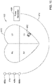
- FIG 10 shows an illustrative medical device system.
- an LCP 402 is shown fixed to the interior of the left ventricle of the heart 410, and a pulse generator 406 is shown coupled to a lead 412 having one or more electrodes 408a-408c.
- the pulse generator 406 may be part of a subcutaneous implantable cardioverter-defibrillator (S-ICD), and the one or more electrodes 408a-408c may be positioned subcutaneously.
- the one or more electrodes 408a-408c may be placed inside of the chest cavity but outside of the heart, such as just interior of the sternum.
- the LCP 402 may communicate with the subcutaneous implantable cardioverter-defibrillator (S-ICD).
- the lead 412 and/or pulse generator 406 may include an accelerometer 414 that may, for example, be configured to sense vibrations that may be indicative of heart sounds.
- the LCP 402 may be in the right ventricle, right atrium, left ventricle or left atrium of the heart, as desired. In some cases, more than one LCP 402 may be implanted. For example, one LCP may be implanted in the right ventricle and another may be implanted in the right atrium. In another example, one LCP may be implanted in the right ventricle and another may be implanted in the left ventricle. In yet another example, one LCP may be implanted in each of the chambers of the heart.
- the housing 612 may include a conductive material and may be insulated along a portion of its length. A section along the proximal end 614 may be free of insulation so as to define the second electrode 622.
- the electrodes 620, 622 may be sensing and/or pacing electrodes to provide electro-therapy and/or sensing capabilities.
- the first electrode 620 may be capable of being positioned against or may otherwise contact the cardiac tissue of the heart while the second electrode 622 may be spaced away from the first electrode 620.
- the first and/or second electrodes 620, 622 may be exposed to the environment outside the housing 612 (e.g. to blood and/or tissue).
- the LCP 610 may include a pulse generator (e.g., electrical circuitry) and a power source (e.g., a battery) within the housing 612 to provide electrical signals to the electrodes 620, 622 to control the pacing/sensing electrodes 620, 622. While not explicitly shown, the LCP 610 may also include, a communications module, an electrical sensing module, a mechanical sensing module, and/or a processing module, and the associated circuitry, similar in form and function to the modules 102, 106, 108, 110 described above. The various modules and electrical circuitry may be disposed within the housing 612. Electrical connections between the pulse generator and the electrodes 620, 622 may allow electrical stimulation to heart tissue and/or sense a physiological condition.
- a pulse generator e.g., electrical circuitry
- a power source e.g., a battery
- the LCP 610 includes a fixation mechanism 624 proximate the distal end 616 of the housing 612.
- the fixation mechanism 624 is configured to attach the LCP 610 to a wall of the heart H, or otherwise anchor the LCP 610 to the anatomy of the patient.
- the fixation mechanism 624 may include one or more, or a plurality of hooks or tines 626 anchored into the cardiac tissue of the heart H to attach the LCP 610 to a tissue wall.
- the fixation mechanism 624 may include one or more, or a plurality of passive tines, configured to entangle with trabeculae within the chamber of the heart H and/or a helical fixation anchor configured to be screwed into a tissue wall to anchor the LCP 610 to the heart H.
- the head portion 632 may have a radial dimension from the longitudinal axis of the LCP 610 that is greater than a radial dimension of the neck portion 634 from the longitudinal axis of the LCP 610.
- the docking member 630 may further include a tether retention structure 636 extending from or recessed within the head portion 632.
- the tether retention structure 636 may define an opening 638 configured to receive a tether or other anchoring mechanism therethrough. While the retention structure 636 is shown as having a generally "U-shaped" configuration, the retention structure 636 may take any shape that provides an enclosed perimeter surrounding the opening 638 such that a tether may be securably and releasably passed (e.g.
- the docking member 630 may be configured to facilitate delivery of the LCP 610 to the intracardiac site and/or retrieval of the LCP 610 from the intracardiac site. While this describes one example docking member 630, it is contemplated that the docking member 630, when provided, can have any suitable configuration.
- the LCP 610 may include one or more pressure sensors 640 coupled to or formed within the housing 612 such that the pressure sensor(s) is exposed to the environment outside the housing 612 to measure blood pressure within the heart. For example, if the LCP 610 is placed in the left ventricle, the pressure sensor(s) 640 may measure the pressure within the left ventricle. If the LCP 610 is placed in another portion of the heart (such as one of the atriums or the right ventricle), the pressures sensor(s) may measure the pressure within that portion of the heart.
- the pressure sensor(s) 640 may include a MEMS device, such as a MEMS device with a pressure diaphragm and piezoresistors on the diaphragm, a piezoelectric sensor, a capacitor-Micro-machined Ultrasonic Transducer (cMUT), a condenser, a micro-monometer, or any other suitable sensor adapted for measuring cardiac pressure.
- the pressures sensor(s) 640 may be part of a mechanical sensing module described herein. It is contemplated that the pressure measurements obtained from the pressures sensor(s) 640 may be used to generate a pressure curve over cardiac cycles. The pressure readings may be taken in combination with impedance measurements (e.g.
- the impedance may be a surrogate for chamber volume, and thus the pressure-impedance loop may be representative for a pressure-volume loop for the heart H.
- the LCP 610 may be configured to measure impedance between the electrodes 620, 622. More generally, the impedance may be measured between other electrode pairs, such as the additional electrodes 114' described above. In some cases, the impedance may be measure between two spaced LCP's, such as two LCP's implanted within the same chamber (e.g. LV) of the heart H, or two LCP's implanted in different chambers of the heart H (e.g. RV and LV). The processing module of the LCP 610 and/or external support devices may derive a measure of cardiac volume from intracardiac impedance measurements made between the electrodes 620, 622 (or other electrodes).
- the processing module of the LCP 610 and/or external support devices may derive a measure of cardiac volume from intracardiac impedance measurements made between the electrodes 620, 622 (or other electrodes).
- the impedance measurement may vary during a cardiac cycle as the volume of blood (and thus the volume of the chamber) surrounding the LCP changes.
- the measure of cardiac volume may be a relative measure, rather than an actual measure.
- the intracardiac impedance may be correlated to an actual measure of cardiac volume via a calibration process, sometimes performed during implantation of the LCP(s). During the calibration process, the actual cardiac volume may be determined using fluoroscopy or the like, and the measured impedance may be correlated to the actual cardiac volume.
- the LCP 610 may be provided with energy delivery circuitry operatively coupled to the first electrode 620 and the second electrode 622 for causing a current to flow between the first electrode 620 and the second electrode 622 in order to determine the impedance between the two electrodes 620, 622 (or other electrode pair). It is contemplated that the energy delivery circuitry may also be configured to deliver pacing pulses via the first and/or second electrodes 620, 622.
- the LCP 610 may further include detection circuitry operatively coupled to the first electrode 620 and the second electrode 622 for detecting an electrical signal received between the first electrode 620 and the second electrode 622. In some instances, the detection circuitry may be configured to detect cardiac signals received between the first electrode 620 and the second electrode 622.
- the detection circuitry may measure a resulting voltage between the first electrode 620 and the second electrode 622 (or between a third and fourth electrode separate from the first electrode 620 and the second electrode 622, not shown) to determine the impedance.
- the detection circuitry may measure a resulting current between the first electrode 620 and the second electrode 622 (or between a third and fourth electrode separate from the first electrode 620 and the second electrode 622) to determine the impedance.
- the impedance may be measured between electrodes on different devices and/or in different heart chambers. For example, impedance may be measured between a first electrode in the left ventricle and a second electrode in the right ventricle. In another example, impedance may be measured between a first electrode of a first LCP in the left ventricle and a second LCP in the left ventricle. In yet another example, impedance may be measured from an injected current.
- a medical device such as, but not limited to an SICD such as the SICD 12 of Figure 1 , may inject a known current into the heart and the LCP implanted in the heart H may measure a voltage resulting from the injected current to determine the impedance.
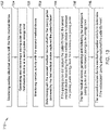
- FIG 12 is a flow diagram showing an illustrative method 700 of sensing and regulating cardiac activity of a patient's heart using a first medical device (such as but not limited to the first medical device 12 of Figure 1 ) that is configured to sense cardiac electrical activity and generate and deliver pacing pulses accordingly, and a second medical device (such as but not limited to the second medical device 14 of Figure 1 ) that is configured to sense cardiac electrical activity.
- the illustrative method 700 includes monitoring cardiac electrical activity with the first medical device, as generally seen at block 702.
- a pacing pulse is generated and delivered with the first medical device at a pacing pulse energy level.
- Cardiac activity may be monitored with the second medical device, as indicated at block 706.
- a determination may be made via the second medical device as to whether the pacing pulse delivered by the first medical device captured the patient's heart. As seen at block 710, if the pacing pulse did not capture the patient's heart, the second medical device may instruct the first medical device to increase the pacing pulse energy level for a subsequent pacing pulse.
- FIG 13 is a flow diagram showing an illustrative method 712 of sensing and regulating cardiac activity of a patient's heart using a first medical device (such as but not limited to the first medical device 12 of Figure 1 ) that is configured to sense cardiac electrical activity and generate and deliver pacing pulses accordingly, and a second medical device (such as but not limited to the second medical device 14 of Figure 1 ) that is configured to sense cardiac electrical activity.
- the illustrative method 712 includes monitoring cardiac electrical activity with the first medical device, as generally seen at block 702.
- a pacing pulse is generated and delivered with the first medical device at a pacing pulse energy level.
- Cardiac activity may be monitored with the second medical device, as indicated at block 706.
- a determination may be made via the second medical device as to whether the pacing pulse delivered by the first medical device captured the patient's heart.
- the second medical device may instruct the first medical device to decrease the pacing pulse energy level for a subsequent pacing pulse.
- the first medical device may generate and deliver the subsequent pacing pulse at a decreased pacing pulse energy level, as seen at block 716.
- the second medical device may monitor cardiac activity to determine if the subsequent pacing pulse captured the patient's heart, as generally seen at block 718.
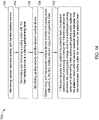
- FIG 14 is a flow diagram showing a method 720 of sensing and regulating cardiac activity of a patient's heart using a first medical device (such as but not limited to the first medical device 12 of Figure 1 ) that is configured to sense cardiac electrical activity and generate and deliver pacing pulses accordingly, and a second medical device (such as but not limited to the second medical device 14 of Figure 1 ) that is configured to sense cardiac electrical activity.
- the method 720 includes monitoring cardiac electrical activity with the first medical device, as generally seen at block 702.
- a pacing pulse is generated and delivered with the first medical device at a pacing pulse energy level.
- Cardiac activity may be monitored with the second medical device, as indicated at block 706.
- a determination may be made with the second medical device as to whether the pacing pulse delivered by the first medical device captured the patient's heart. As seen at block 722, if the pacing pulse did capture the patient's heart, the second medical device may continue to instruct the first medical device to decrease the pacing pulse energy level for a subsequent pacing pulse and determines if the subsequent pacing pulse captured the patient's heart until the second medical device indicates that the subsequent pacing pulse did not capture the patient's heart. In some cases, at this point, the pacing energy may be increased by a safety margin for a subsequent pacing pulse.
Description
- The present disclosure generally relates to cardiac pacemakers, and more particularly, to managing the pace pulse energy of such cardiac pacemakers
- Implantable medical devices are commonly used today to monitor and/or delivery therapy to a patient, including cardiac simulation therapy. Many patients suffer from heart conditions that can result in a reduced ability of the heart to deliver sufficient amounts of blood to the patient's body. Such heart conditions may lead to slow, rapid, irregular, and/or inefficient heart contractions. To help alleviate some of these conditions, various medical devices (e.g., pacemakers, defibrillators, etc.) are often implanted in a patient's body. Such devices may monitor and in some cases provide electrical stimulation (e.g. pacing, defibrillation, etc.) to the heart to help the heart operate in a more normal, efficient and/or safe manner. To extend the effective lifetime of such implanted devices, there is a desire to conserve energy while still providing effective therapy to the patient. Document
US 2014/0107723 A1 relates to a single-chamber leadless intra-cardiac medical device with dual-chamber functionality. - The present disclosure generally relates to cardiac pacemakers, and more particularly, to managing the pace pulse energy of such cardiac pacemakers. In one example, a first medical device, such as a leadless cardiac pacemaker (LCP), may be configured to pace a patient's heart. A separate second medical device may be configured to have a capture threshold capability. The second medical device may monitor the patient's heart to ascertain whether the pacing pulses delivered by the first medical device are capturing the heart or not. The second medical device may be configured to help manage the pace pulse energy delivered by the first medical device by, for example, sending instructions to the first medical device to alter the energy level of one or more subsequent pacing pulses. In some cases, the second medical device may be configured to send an instruction to increase the energy level of one or more subsequent pacing pulses when the second medical device determines that the pacing pulses delivered by the first medical device are not capturing the heart. In some cases, and if the pacing pulses are capturing the heart, the second medical device may be configured to send one or more instructions to sequentially decrease the energy level of one or more subsequent pacing pulses until the pacing pulses no longer capture the heart. The pacing energy may then be increased by a safety margin. This may be useful to help determine the current capture threshold of the heart.
- In another example of the disclosure, a leadless cardiac pacemaker (LCP) may be configured to pace a patient's heart and to be disposable within a chamber of the patient's heart. The LCP may include a housing and a pair of pacing electrodes that are secured relative to the housing. A controller may be disposed within the housing and may be operably coupled to the pair of pacing electrodes. The controller may be configured to generate and deliver a plurality of pacing pulses via the pair of pacing electrodes, where each of the plurality of pacing pulses has a controllable pacing energy level. A communications module may be operably coupled to the controller and may be configured to receive a pacing energy signal from a second implantable medical device that results from an automatic capture threshold capability of the second implantable medical device. In some cases, the pacing energy signal may cause the controller of the LCP to change the pacing energy level of one or more subsequent pacing pulses of the plurality of pacing pulses.
- Alternatively or additionally to any of the embodiments above, the controller may be free of a capture verification capability.
- Alternatively or additionally to any of the embodiments above, the controller may be configured to change the pacing energy level by adjusting a voltage of one or more of the subsequent pacing pulses.
- Alternatively or additionally to any of the embodiments above, the controller may be configured to change the pacing energy level by adjusting a pulse width of one or more of the subsequent pacing pulses.
- Alternatively or additionally to any of the embodiments above, the pacing energy signal may cause the controller to increase the pacing energy level of one or more subsequent pacing pulses of the plurality of pacing pulses.
- Alternatively or additionally to any of the embodiments above, the pacing energy signal may cause the controller to incrementally increase the pacing energy level of two or more subsequent pacing pulses of the plurality of pacing pulses until the communications module receives another signal from the second implantable medical device indicating that the pacing pulses are now capturing the patient's heart.
- Alternatively or additionally to any of the embodiments above, the pacing energy signal may cause the controller to decrease the pacing energy level of one or more subsequent pacing pulses of the plurality of pacing pulses.
- Alternatively or additionally to any of the embodiments above, the pacing energy signal may cause the controller to incrementally decrease the pacing energy level of two or more subsequent pacing pulses of the plurality of pacing pulses until the communications module receives another signal from the second implantable medical device indicating that the pacing pulses are no longer capturing the patient's heart.
- Alternatively or additionally to any of the embodiments above, the controller may be configured to include a safety mode in which the controller generates and delivers pacing pulses at a predetermined energy level when the communications module is not able to receive signals from the second implantable medical device.
- Alternatively or additionally to any of the embodiments above, the controller may be configured to determine when and whether to generate and deliver a pacing pulse based upon electrical cardiac signals received by the LCP.
- In another example of the disclosure, a medical system for sensing and regulating cardiac activity of a patient may include a leadless cardiac pacemaker (LCP) that is configured to pace a patient's heart and to be disposable within a chamber of the patient's heart and a second medical device having an automatic capture threshold capability. The LCP may include a housing and a pair of pacing electrodes secured relative to the housing. A controller may be disposed within the housing and may be operably coupled to the pair of pacing electrodes, the controller may be configured to generate and deliver a plurality of pacing pulses to the heart via the pair of pacing electrodes, each of the plurality of pacing pulses having a controllable pacing energy level. A communications module may be operably coupled to the controller. In the second medical device, the automatic capture threshold capability may be configured to determine whether pacing pulses generated and delivered by the LCP are capturing the heart, and to selectively generate a pacing energy signal to control the pacing energy level of one or more subsequent pacing pulses generated and delivered by the LCP. The communications module of the LCP may be configured to receive the pacing energy signal from the second medical device, and in response, the controller of the LCP may be configured to change the pacing energy level of one or more subsequent pacing pulses of the plurality of pacing pulses.
- Alternatively or additionally to any of the embodiments above, the second medical device may be implantable.
- Alternatively or additionally to any of the embodiments above, the second medical device may include an implantable cardioverter configured to generate and deliver shocks to the patient's heart.
- Alternatively or additionally to any of the embodiments above, the pacing energy signal may cause the controller of the LCP to increase the pacing energy level of one or more subsequent pacing pulses of the plurality of pacing pulses.
- Alternatively or additionally to any of the embodiments above, the pacing energy signal may cause the controller of the LCP to incrementally increase the pacing energy level of two or more subsequent pacing pulses of the plurality of pacing pulses until the communications module receives another signal from the second medical device indicating that the pacing pulses are now capturing the patient's heart.
- Alternatively or additionally to any of the embodiments above, the pacing energy signal may cause the controller of the LCP to decrease the pacing energy level of one or more subsequent pacing pulses of the plurality of pacing pulses.
- Alternatively or additionally to any of the embodiments above, the pacing energy signal may cause the controller of the LCP to incrementally decrease the pacing energy level of two or more subsequent pacing pulses of the plurality of pacing pulses until the communications module receives another signal from the second medical device indicating that the pacing pulses are no longer capturing the patient's heart.
- In another example of the disclosure, a method of sensing and regulating cardiac activity of a patient's heart may use a first medical device that is configured to sense cardiac electrical activity and generate and deliver pacing pulses accordingly and a second medical device that is configured to sense cardiac electrical activity and generate and deliver shocks to cardiac tissue. In some cases, cardiac electrical activity may be monitored with the first medical device. A pacing pulse may be generated and delivered with the first medical device at a pacing pulse energy level. Cardiac activity may be monitored with the second medical device and the second medical device may determine whether the pacing pulse delivered by the first medical device captured the patient's heart. If the pacing pulse did not capture the patient's heart, the second medical device may instruct the first medical device to increase the pacing pulse energy level for a subsequent pacing pulse.
- Alternatively or additionally to any of the embodiments above, the method may further include, if the pacing pulse did capture the patient's heart, the second medical device instructing the first medical device to decrease the pacing pulse energy level for a subsequent pacing pulse. The first medical device may generate and deliver the subsequent pacing pulse at the decreased pacing pulse energy level and the second medical device may monitor cardiac activity to determine if the subsequent pacing pulse captured the patient's heart.
- Alternatively or additionally to any of the embodiments above, the method may further include if the pacing pulse did capture the patient's heart, the second medical device continuing to instruct the first medical device to decrease the pacing pulse energy level for a subsequent pacing pulse and determining if the subsequent pacing pulse captured the patient's heart until the second medical device indicates that the subsequent pacing pulse did not capture the patient's heart.
- The above summary is not intended to describe each embodiment or every implementation of the present disclosure. Advantages and attainments, together with a more complete understanding of the disclosure, will become apparent and appreciated by referring to the following description and claims taken in conjunction with the accompanying drawings.
- The disclosure may be more completely understood in consideration of the following description of various illustrative embodiments in connection with the accompanying drawings, in which:
-
Figure 1 is a highly schematic diagram of an illustrative system in accordance with an example of the disclosure, -
Figure 2 is a high schematic diagram of an illustrative system in accordance with an example of the disclosure; -
Figure 3 is a schematic block diagram of an illustrative leadless cardiac pacemaker (LCP) useable in the system ofFigure 2 ; -
Figure 4 is a schematic block diagram of an illustrative subcutaneous implantable cardioverter defibrillator (SICD) usable in the system ofFigure 2 ; -
Figure 5 is a schematic diagram illustrating a relationship between pacing energy level and cardiac capture status; -
Figure 6 is a schematic diagram illustrating a relationship between pacing energy level and cardiac capture status; -
Figure 7 is a more detailed schematic block diagram of an illustrative LCP in accordance with an example of the disclosure; -
Figure 8 is a schematic block diagram of another illustrative medical device that may be used in conjunction with the LCP ofFigure 7 ; -
Figure 9 is a schematic diagram of an exemplary medical system that includes multiple LCPs and/or other devices in communication with one another; -
Figure 10 is a schematic diagram of a system including an LCP and another medical device, in accordance with an example of the disclosure; -
Figure 11 is a side view of an illustrative implantable leadless cardiac device; -
Figure 12 is a flow diagram of an illustrative method for regulating a patient's heart using the system ofFigure 1 ; -
Figure 13 is a flow diagram of an illustrative method for regulating a patient's heart using the system ofFigure 1 ; and -
Figure 14 is a flow diagram of an illustrative method for regulating a patient's heart using the system ofFigure 1 . - The invention is defined in the appended claims. Aspects, embodiments and examples disclosed herein which do not fall within the scope of the appended claims do not form part of the invention, and are merely provided for illustrative purposes.
- The following description should be read with reference to the drawings in which similar elements in different drawings are numbered the same. The description and the drawings, which are not necessarily to scale, depict illustrative embodiments and are not intended to limit the scope of the disclosure.
- All numbers are herein assumed to be modified by the term "about", unless the content clearly dictates otherwise. The recitation of numerical ranges by endpoints includes all numbers subsumed within that range (e.g., 1 to 5 includes 1, 1.5, 2, 2.75, 3, 3.80, 4, and 5).
- As used in this specification and the appended claims, the singular forms "a", "an", and "the" include the plural referents unless the content clearly dictates otherwise. As used in this specification and the appended claims, the term "or" is generally employed in its sense including "and/or" unless the content clearly dictates otherwise.
- It is noted that references in the specification to "an embodiment", "some embodiments", "other embodiments", etc., indicate that the embodiment described may include a particular feature, structure, or characteristic, but every embodiment may not necessarily include the particular feature, structure, or characteristic. Moreover, such phrases are not necessarily referring to the same embodiment. Further, when a particular feature, structure, or characteristic is described in connection with an embodiment, it is contemplated that the feature, structure, or characteristic may be applied to other embodiments whether or not explicitly described unless clearly stated to the contrary.
- A normal, healthy heart induces contraction by conducting intrinsically generated electrical signals throughout the heart. These intrinsic signals cause the muscle cells or tissue of the heart to contract in a coordinated manner. These contractions forces blood out of and into the heart, providing circulation of the blood throughout the rest of the body. Many patients suffer from cardiac conditions that affect the efficient operation of their hearts. For example, some hearts develop diseased tissue that no longer generate or efficiently conduct intrinsic electrical signals. In some examples, diseased cardiac tissue may conduct electrical signals at differing rates, thereby causing an unsynchronized and inefficient contraction of the heart. In other examples, a heart may generate intrinsic signals at such a low rate that the heart rate becomes dangerously low. In still other examples, a heart may generate electrical signals at an unusually high rate, even resulting in cardiac fibrillation. Implantable medical device are often used to treat such conditions by delivering one or more types of electrical stimulation therapy to the patient's heart.
-
Figure 1 is a schematic diagram showing anillustrative system 10 that may be used to sense and/or pace a heart H. In some cases, thesystem 10 may also be configured to be able to shock the heart H. The heart H includes a right atrium RA and a right ventricle RV. The heart H also includes a left atrium LA and a left ventricle LV. In some cases, thesystem 10 may include a medical device that provides anti-arrhythmic therapy to the heart H. In some cases, thesystem 10 may include a firstmedical device 12 and a secondmedical device 14. In some instances, the firstmedical device 12 may be implantable within the patient at a position near or even within the heart H. In some cases, the secondmedical device 14 may be exterior to the patient. In some cases, the secondmedical device 14 may be implanted within the patient but at a location that is exterior to the heart H. For example, in some cases, the secondmedical device 14 may be implanted at a subcutaneous position within the patient's chest. - In some cases, the first
medical device 12 may be configured to sense electrical cardiac activity of the heart H and to provide pacing pulses to the heart H. In some cases, the firstmedical device 12 may have more than one potential pacing vector available to the firstmedical device 12, and the secondmedical device 14 may be able to determine which of several different pacing vectors are most efficient. It will be appreciated that the energy level necessary for a pacing pulse to capture the heart H may vary from patient to patient or, for a particular patient, may vary as a function of time. In some cases, the energy level necessary for a pacing pulse to capture the heart H may also vary depending on the exact location of the firstmedical device 12 relative to conduction pathways within the heart H, for example. Rather than always pacing at a predetermined pacing energy, which may cause the firstmedical device 12 to expend unnecessary energy if the pacing energy is well above the capture threshold H or fail to capture the heart H if the pacing energy is below the capture threshold of the heart H, the firstmedical device 12 may instead be configured to generate and deliver pacing pulses at a controllable energy level. In some cases, the pacing energy may be increased by increasing the voltage of the pacing pulse and/or increasing the pulse width of the pacing pulse. In some instances, the pacing energy may be decreased by decreasing the voltage of the pacing pulse and/or decreasing the pulse width of the pacing pulse. - In some cases, the second
medical device 14 may be configured to monitor electrical cardiac activity of the heart H, or other indications of cardiac activity, to determine whether the pacing pulses generated and delivered by the firstmedical device 12 are capturing the heart H. In some cases, the secondmedical device 14 may use motion and/or acoustic data from an accelerometer in order to differentiate capture from non-capture. Capturing the heart may be defined as one or more desired chambers of the heart H contracting in response to the pacing pulse. In some cases, the secondmedical device 14 may send a signal to the firstmedical device 12 informing the firstmedical device 12 that a particular pacing pulse did not capture the heart H. In response, the firstmedical device 12 may increase a pacing energy of one or more subsequent pacing pulses. In some cases, the firstmedical device 12 may not include capture verification capability but instead may rely on the secondmedical device 14 to perform that function. In some cases, the secondmedical device 14 may include capture verification capability that may be used by the secondmedical device 14 to verify whether the pacing pulses generated and delivered by the firstmedical device 12 are capturing the heart H. - In some cases, for example, the second
medical device 14 may perform periodic capture threshold tests in order to minimize pacing energy. Periodic capture threshold tests may occur after every ten heart beats, or every twenty heart beats, or any other appropriate interval. In some cases, the secondmedical device 14 may manage pace energy on a beat to beat basis. It may be acceptable to reduce pace energy until capture is lost, then upon loss of capture, increase pace energy for the next beat, and repeat. Settings which result in capture may be used for some pre-determined number of cycles before attempting to reduce energy again, increasing the % of beats at "known good" capture settings. - In some cases, the second
medical device 14, instead of informing the firstmedical device 12 that a particular pacing pulse did not capture the heart H, may instead instruct the firstmedical device 12 to change the pacing energy of one or more subsequent pacing pulses. In other words, in some cases, the firstmedical device 12, upon being informed that a pacing pulse did not capture the heart H, may itself determine an appropriate pacing energy for subsequent pacing pulses. In some cases, the secondmedical device 14 may determine an appropriate pacing energy for subsequent pacing pulses and may instruct the firstmedical device 12 to pace at this appropriate pacing energy. In some cases, the secondmedical device 14 may use advanced understanding of the design of the firstmedical device 12 to optimize pace settings. For example, the firstmedical device 12 may have a power supply architecture with greater efficiency at a given voltage. In some cases, the secondmedical device 14 may, for example, target certain pace voltage and/or pulse width settings in order minimize pacing energy consumption. - By off-loading some or all of the capture verification capability from the first
medical device 12 to the secondmedical device 14, the firstmedical device 12 may be configured to have less processing power, have a smaller form factor, and/or consume less energy. In some instances, for example, the firstmedical device 12 may not be configured to sense cardiac electrical activity and to generate and deliver pacing pulses accordingly, but rather may be configured to just generate and deliver a pacing pulse when instructed to do so by another device such as but not limited to the secondmedical device 14. - In some cases, for example, the second
medical device 14 may be configured to maintain and/or trend pace settings and capture data for the firstmedical device 12 for the purposes of long-term optimization of pace settings. In some cases, the secondmedical device 14 may utilize additional inputs, such as posture, time of day, intrinsic rate, and the like, as inputs to a capture algorithm. For example, the secondmedical device 14 may be able to correlate changes in pace threshold resulting from the other inputs, and proactively adjust pace settings. In some cases, the secondmedical device 14 may be utilized to optimize the AV delay utilized by the firstmedical device 12. For example, the secondmedical device 14 may be able to monitor ECG morphology and/or acceleration data, such as RV or LV pace timing. - In some cases, if the second
medical device 14 is implanted prior to implanting the firstmedical device 12, the secondmedical device 14 may be used to guide optimal placement of the firstmedical device 12, for example, by monitoring the QRS width, morphology, HRV, accelerometer signals, etc. In some cases, the secondmedical device 14 could provide feedback of the attempted firstmedical device 12's location prior to fixation or untethering of the firstmedical device 12. Minimizing QRS width, HRV and certain morphological parameters would be a possible goal of the clinician to obtain such an optimal site, for example. In some cases, the secondmedical device 14 may also be able to monitor the impedance and or heart sounds to possibly detect myocardial functional improvements as indicated by hyperthoprhy, or dialated cardiomyopathy. For example, these diseases generally have increased left ventricles, thus possibly lower impedance and/or contraction changes which could be detected with wall motion during capture or loss of it. - It will be appreciated that in some cases, the first
medical device 12 may have a fail-safe mode in which the firstmedical device 12 generates and delivers pacing pulses at a predetermined pacing voltage and pacing pulse width in the absence of communications from the secondmedical device 14 informing the firstmedical device 12 as to whether the pacing pulses generated and delivered by the firstmedical device 12 are capturing the heart H. In some cases, the pacing voltage and/or pulse width utilized in the fail-safe mode may be factory-set. In some cases, the pacing voltage and/or pulse width utilized in the fail-safe mode may be programmable by a physician, for example. The pacing voltage and pulse width combination utilized in the fail-safe mode may be well above the capture threshold of the heart. -
Figure 2 is a schematic diagram showing anillustrative system 16 that may be used to sense and/or pace a heart H. In some cases, thesystem 16 may be considered as being an example of thesystem 10 shown inFigure 1 . In some cases, thesystem 16 may include a leadless cardiac pacemaker (LCP) 18 and a subcutaneous implantable cardioverter defibrillator (SICD) 20. Accordingly, in some cases theLCP 18 may be considered as being an illustrative but non-limiting example of the firstmedical device 12 and theSICD 20 may be considered as being an illustrative but non-limiting example of the secondmedical device 14 described with respect toFigure 1 . - In some cases, the
LCP 18 may be intracardially implanted. While asingle LCP 18 is illustrated, it will be appreciated that two or more LCPs 18 may be implanted in or on the heart H. TheLCP 18 may be implanted into any chamber of the heart, such as the right atrium RA, the left atrium LA, the right ventricle RV and the left ventricle LV. When more than one LCP is provided, each LCP may be implanted in a different chamber. In some cases, multiple LCP's may be implanted within a single chamber of the heart H. - In some cases, the
SICD 12 may be extracardially implanted. While not shown in this Figure, in some cases theSICD 20 may include a lead/electrode that may be configured to be placed subcutaneously and outside of a patient's sternum. In other cases, the lead/electrode may extend around or through the sternum and may be fixed adjacent an inner surface of the sternum. In both cases, the lead/electrode is positioned extracardially (outside of the patient's heart). TheSICD 20 may be configured to sense electrical activity generated by the heart H as well as provide electrical energy to the heart H in order to shock the heart H from an undesired heart rhythm to a desired heart rhythm. - In some cases, the
LCP 18 and theSICD 20 may be implanted at the same time. In some instances, depending on the cardiac deficiencies of a particular patient, theSICD 20 may be implanted first, and one or more LCPs 18 may be implanted at a later date if/when the patient develops indications for receiving cardiac resynchronization therapy and/or it becomes necessary to pace the heart H. In some cases, it is contemplated that one or more LCPs 18 may be implanted first, in order to sense and pace the heart H. When a need for possible defibrillation becomes evident, theSICD 20 may subsequently be implanted. Regardless of implantation order or sequence, it will be appreciated that theLCP 18 and theSICD 20 may communicate with each other using any desired communications modality, such as conducted communication, inductive communication, acoustic communication, RF communication, optical communication and/or using any other suitable communication modality. -
Figure 3 is a schematic diagram of an illustrative leadless cardiac pacemaker (LCP) 18. In some cases, theLCP 18 includes ahousing 22 and a pair ofelectrodes housing 22. While twoelectrodes LCP 18 may include three or more electrodes. Acontroller 28 is disposed within thehousing 22 and may be operably coupled to the pair ofelectrodes electrical connectors power supply 30 is operably coupled to thecontroller 28 and provides power for operation of thecontroller 28 as well as providing power for generating pacing pulses that can be delivered via the pair ofelectrodes controller 28 may be considered as being configured to generate and deliver a plurality of pacing pulses via the pair ofelectrodes controller 28 may control the pacing voltage and/or the pacing pulse width. - In some cases, the
LCP 18 may include acommunications module 32 that is operably coupled to thecontroller 28. Thecommunications module 32 may be configured to receive a pacing energy signal from a second implantable medical device such as but not limited to the second medical device 14 (Figure 1 ) or the SICD 20 (Figure 2 ). The pacing energy signal received by thecommunications module 32 may, for example, result from an automatic capture threshold capability of the second implantablemedical device 14. In some cases, the pacing energy signal causes thecontroller 28 of theLCP 18 to change the pacing energy level of one or more subsequent pacing pulses of the plurality of pacing pulses. In some cases, the pacing energy signal may merely indicate that the previous pace pulse did not capture the heart H, and thecontroller 28 determines the pacing energy level of the one or more subsequent pacing pulses. In other cases, the pacing energy signal may encode an energy level calculated by the second implantablemedical device 14 for one or more subsequent pacing pulses, and thecontroller 28 of theLCP 18 may provide one or more pacing pulses with the encoded energy level. In yet other cases, the pacing energy signal may include an instruction or command that commands theLCP 18 to change the pacing energy level (e.g. pacing voltage, pacing pulse width, or both) to a commanded energy level. In some cases, the command may provide a particular pacing voltage, pulse width or both, or may instruct theLCP 18 to increment the pacing energy by an offset amount. These are just examples. It is contemplated that the pacing energy signal may take on any form that is suitable for causing theLCP 18 to change the pacing energy level in a desired manner. - In some cases, the
controller 28 of theLCP 18 may not include any capture verification capability itself and thus may rely upon the second implantable medical device to provide this capability. In some cases, thecontroller 28 may be configured to change the pacing energy level by adjusting a voltage of one or more of the subsequent pacing pulses after receiving the pacing energy signal. In some instances, thecontroller 28 may be configured to change the pacing energy level by adjusting a pulse width of one or more of the subsequent pacing pulses after receiving the pacing energy signal. In some instances, thecontroller 28 may be configured to change the pacing energy level by adjusting a voltage and pulse width of one or more of the subsequent pacing pulses after receiving the pacing energy signal. - In some cases, the pacing energy signal received by the
communications module 32 may cause thecontroller 28 to increase the pacing energy level of one or more of the subsequent pacing pulses. In some cases, the pacing energy signal received by thecommunications module 32 may cause thecontroller 28 to incrementally increase the pacing energy level of two or more subsequent pacing pulses of the plurality of pacing pulses until thecommunications module 32 receives another signal from the second implantable medical device indicating that the pacing pulses are now capturing the heart H. In some cases, once thecommunications module 32 receives the signal indicating capture, thecontroller 28 may increase the pacing energy level of a subsequent pacing pulse by a safety margin to help ensure capture. Such a routine may be periodically initiated by the second medical device as part of an automatic capture threshold capability of the second medical device. - In some cases, the pacing energy signal may cause the
controller 28 to decrease the pacing energy level of one or more subsequent pacing pulses of the plurality of pacing pulses. In some cases, the pacing energy signal may cause thecontroller 28 to incrementally decrease the pacing energy level of two or more subsequent pacing pulses of the plurality of pacing pulses until thecommunications module 32 receives another signal from the second implantable medical device indicating that the pacing pulses are no longer capturing the patient's heart. In some cases, once thecommunications module 32 receives the signal indicating loss of capture, thecontroller 28 may increase the pacing energy level of a subsequent pacing pulse by a safety margin to help ensure capture. Such a routine may be periodically initiated by the second medical device as part of an automatic capture threshold capability of the second medical device. - In some cases, it will be appreciated that there may be gaps in communication between the
LCP 18 and the second implantable medical device. These gaps may be short-lived, or may be of longer duration. In some instances, thecontroller 28 may be configured to include a safety mode in which thecontroller 28 generates and delivers pacing pulses at a predetermined energy level when thecommunications module 32 is not able to receive signals from the second implantable medical device. In some cases, thecontroller 28 may be configured to determine when and whether to generate and deliver a pacing pulse based upon electrical cardiac signals received by theLCP 18. In some cases,LCP 18 may be configured to determine ifcommunications module 32 is able to receive signals by receiving an acknowledge signal in response to a communication transmitted by theLCP 18, by receiving periodic pings transmitted by the second implantable medical device, and/or in any other suitable manner. -
Figure 4 is a schematic illustration of the subcutaneous implantable cardioverter defibrillator (SICD) 20. In some cases, theSICD 20 includes ahousing 42 and anelectrode support 44 that is operably coupled to thehousing 42. In some cases, theelectrode support 44 may be configured to place one or more electrodes in a position, such as subcutaneous or sub-sternal, that enables the one or more electrodes to detect cardiac electrical activity as well as to be able to deliver electrical shocks when appropriate to the heart H. In the example shown, thehousing 42 includes acontroller 46, apower supply 48 and acommunications module 50. As illustrated, theelectrode support 44 includes afirst electrode 52, asecond electrode 54 and athird electrode 56. In some cases, theelectrode support 44 may include fewer or more electrodes. In some cases, theSICD 20 may include one or more other sensors such as an accelerometer or a gyro, for example. - It will be appreciated that the
SICD 20 may include additional components which are not illustrated here for simplicity. In the example shown, thepower supply 48 is operably coupled to thecontroller 46 and provides thecontroller 46 with power to operate thecontroller 46, to send electrical power to the electrodes on or in theelectrode support 44, and to send signals to thecommunications module 50, as appropriate. In some cases, thecontroller 46 may be configured to include an automatic capture threshold capability. In some cases, for example, thecontroller 46 may receive pacing pulses of the LCP 18 (Figure 3 ) and at least part of an electrocardiogram (ECG) via two or more of theelectrodes LCP 18 are capturing the heart H. In some cases, thecontroller 46 determines whether the pacing pulses are capturing the heart H, and communicates a simple CAPTURE message or a NOT CAPTURED message to theLCP 18 via thecommunications module 50. In some cases, thecontroller 46 determines whether the pacing pulses are capturing the heart H, and communicate a pacing energy level signal to theLCP 18 instructing theLCP 18 to adjust the pacing energy for subsequent pacing pulses. These are just examples. -
Figure 5 shows agraph 60 that illustrates a possible relationship between pacing energy level and cardiac capture status. Thegraph 60 includes a pacingenergy plotline 62 and acapture heart plotline 64. Initially, the pacing energy is at a level denoted by 62a and the capture heart status is NO CAPTURE, as indicated at 64a. As a result, the pacing energy is increased to a level denoted by 62b and the heart capture status is checked again. As can be seen at 64b, the capture heart status is still NO CAPTURE. The pacing energy is increased again to a level denoted by 62c and the heart capture status is checked again. As can be seen at 64c, the capture heart status is now YES. In some cases, as illustrated, the pacing energy remains at the level denoted by 62c. In some cases, while not illustrative, the pacing energy may be increased abovelevel 62c by a safety margin to help ensure subsequent pacing pulses capture the heart H. In some cases, while not illustrated, the pacing energy may be decreased again after a period of time, to see if capture may be achieved at a lower pacing energy level. -
Figure 6 shows agraph 66 that illustrates a possible relationship between pacing energy level and cardiac capture status. Thegraph 66 includes a pacingenergy plotline 68 and acapture heart plotline 70. Initially, the pacing energy is at a level denoted by 68a and the capture heart status is YES, as indicated at 70a. As a result, the pacing energy may be decreased to a level denoted by 68b, and the capture heart status may be checked again. As can be seen at 70b, the capture heart status remains YES, and so the pacing energy may be decreased to a level denoted by 70c and the capture heart status may be checked again. As can be seen at 70c, the capture heart status remains YES, and so the pacing energy may be decreased to a level denoted by 68d. The capture heart status has now changed to NO CAPTURE, as seen at 70d. As a result, the pacing energy may be increases to a level denoted by 68e and the capture heart status may be checked again. In some cases, the pacingenergy level 68e may be equal to the pacingenergy level 68c. In some cases, the pacingenergy level 68e may represent a smaller change in energy level. In some cases, as illustrated, the pacing energy remains at the level denoted by 68e. In some cases, while not illustrative, the pacing energy may be increased abovelevel 68e by a safety margin to help ensure subsequent pacing pulses capture the heart H. In some cases, while not illustrated, the pacing energy may be decreased again after a period of time, to see if capture may be achieved at a lower pacing energy level. -
Figure 5 and6 illustrate example routines that might be implemented by an automatic capture threshold capability. In some cases, the firstmedical device 12 may have an automatic capture threshold capability and may implement one or more of these routines. When so provided, the secondmedical device 14 may determine if each pacing pulse provided by the first medical device captured the heart H or not, and may communicate that information to the firstmedical device 12. On some cases, the automatic capture threshold capability may be distributed between the firstmedical device 12 and the secondmedical device 14. In yet other cases, the firstmedical device 12 may not include an automatic capture threshold capability, but rather may rely on an automatic capture threshold capability of the secondmedical device 14 to provide instructions to the firstmedical device 12 to set the pacing energy level for subsequent pacing pulses. These are just examples. -
Figure 7 depicts another illustrative leadless cardiac pacemaker (LCP) that may be implanted into a patient and may operate to deliver appropriate therapy to the heart, such as to deliver anti-tachycardia pacing (ATP) therapy, cardiac resynchronization therapy (CRT), bradycardia therapy, and/or the like. As can be seen inFigure 7 , theLCP 100 may be a compact device with all components housed within the or directly on ahousing 120. In some cases, theLCP 100 may be considered as being an example of the LCP 18 (Figure 1 ). In the example shown inFigure 7 , theLCP 100 may include acommunication module 102, apulse generator module 104, anelectrical sensing module 106, amechanical sensing module 108, aprocessing module 110, abattery 112, and anelectrode arrangement 114. TheLCP 100 may include more or less modules, depending on the application. - The
communication module 102 may be configured to communicate with devices such as sensors, other medical devices such as an SICD, and/or the like, that are located externally to theLCP 100. Such devices may be located either external or internal to the patient's body. Irrespective of the location, external devices (i.e. external to theLCP 100 but not necessarily external to the patient's body) can communicate with theLCP 100 viacommunication module 102 to accomplish one or more desired functions. For example, theLCP 100 may communicate information, such as sensed electrical signals, data, instructions, messages, R-wave detection markers, etc., to an external medical device (e.g. SICD and/or programmer) through thecommunication module 102. The external medical device may use the communicated signals, data, instructions, messages, R-wave detection markers, etc., to perform various functions, such as determining occurrences of arrhythmias, delivering electrical stimulation therapy, storing received data, and/or performing any other suitable function. TheLCP 100 may additionally receive information such as signals, data, instructions and/or messages from the external medical device through thecommunication module 102, and theLCP 100 may use the received signals, data, instructions and/or messages to perform various functions, such as determining occurrences of arrhythmias, delivering electrical stimulation therapy, storing received data, and/or performing any other suitable function. Thecommunication module 102 may be configured to use one or more methods for communicating with external devices. For example, thecommunication module 102 may communicate via radiofrequency (RF) signals, inductive coupling, optical signals, acoustic signals, conducted communication signals, and/or any other signals suitable for communication. - In the example shown in
Figure 7 , thepulse generator module 104 may be electrically connected to theelectrodes 114. In some examples, theLCP 100 may additionally include electrodes 114'. In such examples, thepulse generator 104 may also be electrically connected to the electrodes 114'. Thepulse generator module 104 may be configured to generate electrical stimulation signals. For example, thepulse generator module 104 may generate and deliver electrical stimulation signals by using energy stored in thebattery 112 within theLCP 100 and deliver the generated electrical stimulation signals via theelectrodes 114 and/or 114'. Alternatively, or additionally, thepulse generator 104 may include one or more capacitors, and thepulse generator 104 may charge the one or more capacitors by drawing energy from thebattery 112. Thepulse generator 104 may then use the energy of the one or more capacitors to deliver the generated electrical stimulation signals via theelectrodes 114 and/or 114'. In at least some examples, thepulse generator 104 of theLCP 100 may include switching circuitry to selectively connect one or more of theelectrodes 114 and/or 114' to thepulse generator 104 in order to select which of theelectrodes 114/114' (and/or other electrodes) thepulse generator 104 delivers the electrical stimulation therapy. Thepulse generator module 104 may generate and deliver electrical stimulation signals with particular features or in particular sequences in order to provide one or multiple of a number of different stimulation therapies. For example, thepulse generator module 104 may be configured to generate electrical stimulation signals to provide electrical stimulation therapy to combat bradycardia, tachycardia, cardiac synchronization, bradycardia arrhythmias, tachycardia arrhythmias, fibrillation arrhythmias, cardiac synchronization arrhythmias and/or to produce any other suitable electrical stimulation therapy. Some more common electrical stimulation therapies include anti-tachycardia pacing (ATP) therapy, cardiac resynchronization therapy (CRT), and cardioversion/defibrillation therapy. In some cases, thepulse generator 104 may provide a controllable pulse energy. In some cases, thepulse generator 104 may allow the controller to control the pulse voltage, pulse width, pulse shape or morphology, and/or any other suitable pulse characteristic. - In some examples, the
LCP 100 may include anelectrical sensing module 106, and in some cases, amechanical sensing module 108. Theelectrical sensing module 106 may be configured to sense the cardiac electrical activity of the heart. For example, theelectrical sensing module 106 may be connected to theelectrodes 114/114', and theelectrical sensing module 106 may be configured to receive cardiac electrical signals conducted through theelectrodes 114/114'. The cardiac electrical signals may represent local information from the chamber in which theLCP 100 is implanted. For instance, if theLCP 100 is implanted within a ventricle of the heart (e.g. RV, LV), cardiac electrical signals sensed by theLCP 100 through theelectrodes 114/114' may represent ventricular cardiac electrical signals. In some cases, theLCP 100 may be configured to detect cardiac electrical signals from other chambers (e.g. far field), such as the P-wave from the atrium. - The
mechanical sensing module 108 may include one or more sensors, such as an accelerometer, a pressure sensor, a heart sound sensor, a blood-oxygen sensor, a chemical sensor, a temperature sensor, a flow sensor and/or any other suitable sensors that are configured to measure one or more mechanical/chemical parameters of the patient. Both theelectrical sensing module 106 and themechanical sensing module 108 may be connected to aprocessing module 110, which may provide signals representative of the sensed mechanical parameters. Although described with respect toFigure 7 as separate sensing modules, in some cases, theelectrical sensing module 206 and themechanical sensing module 208 may be combined into a single sensing module, as desired. - The
electrodes 114/114' can be secured relative to thehousing 120 but exposed to the tissue and/or blood surrounding theLCP 100. In some cases, theelectrodes 114 may be generally disposed on either end of theLCP 100 and may be in electrical communication with one or more of themodules electrodes 114/114' may be supported by thehousing 120, although in some examples, theelectrodes 114/114' may be connected to thehousing 120 through short connecting wires such that theelectrodes 114/114' are not directly secured relative to thehousing 120. In examples where theLCP 100 includes one or more electrodes 114', the electrodes 114' may in some cases be disposed on the sides of theLCP 100, which may increase the number of electrodes by which theLCP 100 may sense cardiac electrical activity, deliver electrical stimulation and/or communicate with an external medical device. Theelectrodes 114/114' can be made up of one or more biocompatible conductive materials such as various metals or alloys that are known to be safe for implantation within a human body. In some instances, theelectrodes 114/114' connected to theLCP 100 may have an insulative portion that electrically isolates theelectrodes 114/114' from adjacent electrodes, thehousing 120, and/or other parts of theLCP 100. In some cases, one or more of theelectrodes 114/114' may be provided on a tail (not shown) that extends away from thehousing 120. - The
processing module 110 can be configured to control the operation of theLCP 100. For example, theprocessing module 110 may be configured to receive electrical signals from theelectrical sensing module 106 and/or themechanical sensing module 108. Based on the received signals, theprocessing module 110 may determine, for example, abnormalities in the operation of the heart H. Based on any determined abnormalities, theprocessing module 110 may control thepulse generator module 104 to generate and deliver electrical stimulation in accordance with one or more therapies to treat the determined abnormalities. Theprocessing module 110 may further receive information from thecommunication module 102. In some examples, theprocessing module 110 may use such received information to help determine whether an abnormality is occurring, determine a type of abnormality, and/or to take particular action in response to the information. Theprocessing module 110 may additionally control thecommunication module 102 to send/receive information to/from other devices. - In some examples, the
processing module 110 may include a pre-programmed chip, such as a very-large-scale integration (VLSI) chip and/or an application specific integrated circuit (ASIC). In such embodiments, the chip may be pre-programmed with control logic in order to control the operation of theLCP 100. By using a pre-programmed chip, theprocessing module 110 may use less power than other programmable circuits (e.g. general purpose programmable microprocessors) while still being able to maintain basic functionality, thereby potentially increasing the battery life of theLCP 100. In other examples, theprocessing module 110 may include a programmable microprocessor. Such a programmable microprocessor may allow a user to modify the control logic of theLCP 100 even after implantation, thereby allowing for greater flexibility of theLCP 100 than when using a pre-programmed ASIC. In some examples, theprocessing module 110 may further include a memory, and theprocessing module 110 may store information on and read information from the memory. In other examples, theLCP 100 may include a separate memory (not shown) that is in communication with theprocessing module 110, such that theprocessing module 110 may read and write information to and from the separate memory. - The
battery 112 may provide power to theLCP 100 for its operations. In some examples, thebattery 112 may be a non-rechargeable lithium-based battery. In other examples, a non-rechargeable battery may be made from other suitable materials, as desired. Because theLCP 100 is an implantable device, access to theLCP 100 may be limited after implantation. Accordingly, it is desirable to have sufficient battery capacity to deliver therapy over a period of treatment such as days, weeks, months, years or even decades. In some instances, thebattery 112 may a rechargeable battery, which may help increase the useable lifespan of theLCP 100. In still other examples, thebattery 112 may be some other type of power source, as desired. - To implant the
LCP 100 inside a patient's body, an operator (e.g., a physician, clinician, etc.), may fix theLCP 100 to the cardiac tissue of the patient's heart. To facilitate fixation, theLCP 100 may include one or more anchors 116. Theanchor 116 may include any one of a number of fixation or anchoring mechanisms. For example, theanchor 116 may include one or more pins, staples, threads, screws, helix, tines, and/or the like. In some examples, although not shown, theanchor 116 may include threads on its external surface that may run along at least a partial length of theanchor 116. The threads may provide friction between the cardiac tissue and the anchor to help fix theanchor 116 within the cardiac tissue. In other examples, theanchor 116 may include other structures such as barbs, spikes, or the like to facilitate engagement with the surrounding cardiac tissue. -
Figure 8 depicts an example of another or second medical device (MD) 200, which may be used in conjunction with the LCP 100 (Figure 7 ) in order to detect and/or treat cardiac abnormalities. In some cases, theMD 200 may be considered as an example of the SICD 20 (Figure 2 ). In the example shown, theMD 200 may include acommunication module 202, apulse generator module 204, anelectrical sensing module 206, amechanical sensing module 208, aprocessing module 210, and abattery 218. Each of these modules may be similar to themodules LCP 100. Additionally, thebattery 218 may be similar to thebattery 112 of theLCP 100. In some examples, however, theMD 200 may have a larger volume within thehousing 220. In such examples, theMD 200 may include a larger battery and/or alarger processing module 210 capable of handling more complex operations than theprocessing module 110 of theLCP 100. - While it is contemplated that the
MD 200 may be another leadless device such as shown inFigure 7 , in some instances theMD 200 may include leads such as leads 212. The leads 212 may include electrical wires that conduct electrical signals between theelectrodes 214 and one or more modules located within thehousing 220. In some cases, theleads 212 may be connected to and extend away from thehousing 220 of theMD 200. In some examples, theleads 212 are implanted on, within, or adjacent to a heart of a patient. The leads 212 may contain one ormore electrodes 214 positioned at various locations on theleads 212, and in some cases at various distances from thehousing 220. Some leads 212 may only include asingle electrode 214, while other leads 212 may includemultiple electrodes 214. Generally, theelectrodes 214 are positioned on theleads 212 such that when theleads 212 are implanted within the patient, one or more of theelectrodes 214 are positioned to perform a desired function. In some cases, the one or more of theelectrodes 214 may be in contact with the patient's cardiac tissue. In some cases, the one or more of theelectrodes 214 may be positioned subcutaneously and outside of the patient's heart. In some cases, theelectrodes 214 may conduct intrinsically generated electrical signals to theleads 212, e.g. signals representative of intrinsic cardiac electrical activity. The leads 212 may, in turn, conduct the received electrical signals to one or more of themodules MD 200. In some cases, theMD 200 may generate electrical stimulation signals, and theleads 212 may conduct the generated electrical stimulation signals to theelectrodes 214. Theelectrodes 214 may then conduct the electrical signals and delivery the signals to the patient's heart (either directly or indirectly). - The
mechanical sensing module 208, as with themechanical sensing module 108, may contain or be electrically connected to one or more sensors, such as accelerometers, acoustic sensors, blood pressure sensors, heart sound sensors, blood-oxygen sensors, and/or other sensors which are configured to measure one or more mechanical/chemical parameters of the heart and/or patient. In some examples, one or more of the sensors may be located on theleads 212, but this is not required. In some examples, one or more of the sensors may be located in thehousing 220. - While not required, in some examples, the
MD 200 may be an implantable medical device. In such examples, thehousing 220 of theMD 200 may be implanted in, for example, a transthoracic region of the patient. Thehousing 220 may generally include any of a number of known materials that are safe for implantation in a human body and may, when implanted, hermetically seal the various components of theMD 200 from fluids and tissues of the patient's body. - In some cases, the
MD 200 may be an implantable cardiac pacemaker (ICP). In this example, theMD 200 may have one or more leads, for example theleads 212, which are implanted on or within the patient's heart. The one or more leads 212 may include one ormore electrodes 214 that are in contact with cardiac tissue and/or blood of the patient's heart. TheMD 200 may be configured to sense intrinsically generated cardiac electrical signals and determine, for example, one or more cardiac arrhythmias based on analysis of the sensed signals. TheMD 200 may be configured to deliver CRT, ATP therapy, bradycardia therapy, and/or other therapy types via theleads 212 implanted within the heart. In some examples, theMD 200 may additionally be configured provide defibrillation therapy. - In some instances, the
MD 200 may be an implantable cardioverter-defibrillator (ICD). In such examples, theMD 200 may include one or more leads implanted within a patient's heart. TheMD 200 may also be configured to sense cardiac electrical signals, determine occurrences of tachyarrhythmias based on the sensed signals, and may be configured to deliver defibrillation therapy in response to determining an occurrence of a tachyarrhythmia. In other examples, theMD 200 may be a subcutaneous implantable cardioverter-defibrillator (S-ICD). In examples where theMD 200 is an S-ICD, one of theleads 212 may be a subcutaneously implanted lead. In at least some examples where theMD 200 is an S-ICD, theMD 200 may include only a single lead which is implanted subcutaneously, but this is not required. In some instances, the lead(s) may have one or more electrodes that are placed subcutaneously and outside of the chest cavity. In other examples, the lead(s) may have one or more electrodes that are placed inside of the chest cavity, such as just interior of the sternum but outside of the heart H. - In some examples, the
MD 200 may not be an implantable medical device. Rather, theMD 200 may be a device external to the patient's body, and may include skin-electrodes that are placed on a patient's body. In such examples, theMD 200 may be able to sense surface electrical signals (e.g. cardiac electrical signals that are generated by the heart or electrical signals generated by a device implanted within a patient's body and conducted through the body to the skin). In such examples, theMD 200 may be configured to deliver various types of electrical stimulation therapy, including, for example, defibrillation therapy. -
Figure 10 illustrates an example of a medical device system and a communication pathway through which multiplemedical devices medical device system 300 may includeLCPs medical device 306, and other sensors/devices 310. Theexternal device 306 may be any of the devices described previously with respect to theMD 200. Other sensors/devices 310 may also be any of the devices described previously with respect to theMD 200. In some instances, other sensors/devices 310 may include a sensor, such as an accelerometer, an acoustic sensor, a blood pressure sensor, or the like. In some cases, other sensors/devices 310 may include an external programmer device that may be used to program one or more devices of thesystem 300. - Various devices of the
system 300 may communicate viacommunication pathway 308. For example, theLCPs 302 and/or 304 may sense intrinsic cardiac electrical signals and may communicate such signals to one or moreother devices 302/304, 306, and 310 of thesystem 300 viacommunication pathway 308. In one example, one or more of thedevices 302/304 may receive such signals and, based on the received signals, determine an occurrence of an arrhythmia. In some cases, the device ordevices 302/304 may communicate such determinations to one or moreother devices system 300. In some cases, one or more of thedevices 302/304, 306, and 310 of thesystem 300 may take action based on the communicated determination of an arrhythmia, such as by delivering a suitable electrical stimulation to the heart of the patient. It is contemplated that thecommunication pathway 308 may communicate using RF signals, inductive coupling, optical signals, acoustic signals, or any other signals suitable for communication. Additionally, in at least some examples,device communication pathway 308 may include multiple signal types. For instance, other sensors/device 310 may communicate with theexternal device 306 using a first signal type (e.g. RF communication) but communicate with theLCPs 302/304 using a second signal type (e.g. conducted communication). Further, in some examples, communication between devices may be limited. For instance, as described above, in some examples, theLCPs 302/304 may communicate with theexternal device 306 only through other sensors/devices 310, where theLCPs 302/304 send signals to other sensors/devices 310, and other sensors/devices 310 relay the received signals to theexternal device 306. - In some cases, the
communication pathway 308 may include conducted communication. Accordingly, devices of thesystem 300 may have components that allow for such conducted communication. For instance, the devices ofsystem 300 may be configured to transmit conducted communication signals (e.g. current and/or voltage pulses) into the patient's body via one or more electrodes of a transmitting device, and may receive the conducted communication signals (e.g. pulses) via one or more electrodes of a receiving device. The patient's body may "conduct" the conducted communication signals (e.g. pulses) from the one or more electrodes of the transmitting device to the electrodes of the receiving device in thesystem 300. In such examples, the delivered conducted communication signals (e.g. pulses) may differ from pacing or other therapy signals. For example, the devices of thesystem 300 may deliver electrical communication pulses at an amplitude /pulse width that is sub-capture threshold to the heart. Although, in some cases, the amplitude/pulse width of the delivered electrical communication pulses may be above the capture threshold of the heart, but may be delivered during a blanking period of the heart (e.g. refractory period) and/or may be incorporated in or modulated onto a pacing pulse, if desired. - Delivered electrical communication pulses may be modulated in any suitable manner to encode communicated information. In some cases, the communication pulses may be pulse width modulated or amplitude modulated. Alternatively, or in addition, the time between pulses may be modulated to encode desired information. In some cases, conducted communication pulses may be voltage pulses, current pulses, biphasic voltage pulses, biphasic current pulses, or any other suitable electrical pulse as desired.
-
Figure 10 shows an illustrative medical device system. InFigure 10 , anLCP 402 is shown fixed to the interior of the left ventricle of theheart 410, and apulse generator 406 is shown coupled to a lead 412 having one ormore electrodes 408a-408c. In some cases, thepulse generator 406 may be part of a subcutaneous implantable cardioverter-defibrillator (S-ICD), and the one ormore electrodes 408a-408c may be positioned subcutaneously. In some cases, the one ormore electrodes 408a-408c may be placed inside of the chest cavity but outside of the heart, such as just interior of the sternum. - In some cases, the
LCP 402 may communicate with the subcutaneous implantable cardioverter-defibrillator (S-ICD). In some cases, thelead 412 and/orpulse generator 406 may include anaccelerometer 414 that may, for example, be configured to sense vibrations that may be indicative of heart sounds. - In some cases, the
LCP 402 may be in the right ventricle, right atrium, left ventricle or left atrium of the heart, as desired. In some cases, more than oneLCP 402 may be implanted. For example, one LCP may be implanted in the right ventricle and another may be implanted in the right atrium. In another example, one LCP may be implanted in the right ventricle and another may be implanted in the left ventricle. In yet another example, one LCP may be implanted in each of the chambers of the heart. -
Figure 11 is a side view of an illustrative implantable leadless cardiac pacemaker (LCP) 610. TheLCP 610 may be similar in form and function to theLCP 100 described above. TheLCP 610 may include any of the modules and/or structural features described above with respect to theLCP 100 described above. TheLCP 610 may include a shell orhousing 612 having aproximal end 614 and adistal end 616. Theillustrative LCP 610 includes a first electrode 620 secured relative to thehousing 612 and positioned adjacent to thedistal end 616 of thehousing 612 and asecond electrode 622 secured relative to thehousing 612 and positioned adjacent to theproximal end 614 of thehousing 612. In some cases, thehousing 612 may include a conductive material and may be insulated along a portion of its length. A section along theproximal end 614 may be free of insulation so as to define thesecond electrode 622. Theelectrodes 620, 622 may be sensing and/or pacing electrodes to provide electro-therapy and/or sensing capabilities. The first electrode 620 may be capable of being positioned against or may otherwise contact the cardiac tissue of the heart while thesecond electrode 622 may be spaced away from the first electrode 620. The first and/orsecond electrodes 620, 622 may be exposed to the environment outside the housing 612 (e.g. to blood and/or tissue). - In some cases, the
LCP 610 may include a pulse generator (e.g., electrical circuitry) and a power source (e.g., a battery) within thehousing 612 to provide electrical signals to theelectrodes 620, 622 to control the pacing/sensing electrodes 620, 622. While not explicitly shown, theLCP 610 may also include, a communications module, an electrical sensing module, a mechanical sensing module, and/or a processing module, and the associated circuitry, similar in form and function to themodules housing 612. Electrical connections between the pulse generator and theelectrodes 620, 622 may allow electrical stimulation to heart tissue and/or sense a physiological condition. - In the example shown, the
LCP 610 includes a fixation mechanism 624 proximate thedistal end 616 of thehousing 612. The fixation mechanism 624 is configured to attach theLCP 610 to a wall of the heart H, or otherwise anchor theLCP 610 to the anatomy of the patient. In some instances, the fixation mechanism 624 may include one or more, or a plurality of hooks ortines 626 anchored into the cardiac tissue of the heart H to attach theLCP 610 to a tissue wall. In other instances, the fixation mechanism 624 may include one or more, or a plurality of passive tines, configured to entangle with trabeculae within the chamber of the heart H and/or a helical fixation anchor configured to be screwed into a tissue wall to anchor theLCP 610 to the heart H. These are just examples. - The
LCP 610 may further include adocking member 630 proximate theproximal end 614 of thehousing 612. Thedocking member 630 may be configured to facilitate delivery and/or retrieval of theLCP 610. For example, thedocking member 630 may extend from theproximal end 614 of thehousing 612 along a longitudinal axis of thehousing 612. Thedocking member 630 may include ahead portion 632 and aneck portion 634 extending between thehousing 612 and thehead portion 632. Thehead portion 632 may be an enlarged portion relative to theneck portion 634. For example, thehead portion 632 may have a radial dimension from the longitudinal axis of theLCP 610 that is greater than a radial dimension of theneck portion 634 from the longitudinal axis of theLCP 610. In some cases, thedocking member 630 may further include atether retention structure 636 extending from or recessed within thehead portion 632. Thetether retention structure 636 may define anopening 638 configured to receive a tether or other anchoring mechanism therethrough. While theretention structure 636 is shown as having a generally "U-shaped" configuration, theretention structure 636 may take any shape that provides an enclosed perimeter surrounding theopening 638 such that a tether may be securably and releasably passed (e.g. looped) through theopening 638. In some cases, theretention structure 636 may extend though thehead portion 632, along theneck portion 634, and to or into theproximal end 614 of thehousing 612. Thedocking member 630 may be configured to facilitate delivery of theLCP 610 to the intracardiac site and/or retrieval of theLCP 610 from the intracardiac site. While this describes oneexample docking member 630, it is contemplated that thedocking member 630, when provided, can have any suitable configuration. - It is contemplated that the
LCP 610 may include one ormore pressure sensors 640 coupled to or formed within thehousing 612 such that the pressure sensor(s) is exposed to the environment outside thehousing 612 to measure blood pressure within the heart. For example, if theLCP 610 is placed in the left ventricle, the pressure sensor(s) 640 may measure the pressure within the left ventricle. If theLCP 610 is placed in another portion of the heart (such as one of the atriums or the right ventricle), the pressures sensor(s) may measure the pressure within that portion of the heart. The pressure sensor(s) 640 may include a MEMS device, such as a MEMS device with a pressure diaphragm and piezoresistors on the diaphragm, a piezoelectric sensor, a capacitor-Micro-machined Ultrasonic Transducer (cMUT), a condenser, a micro-monometer, or any other suitable sensor adapted for measuring cardiac pressure. The pressures sensor(s) 640 may be part of a mechanical sensing module described herein. It is contemplated that the pressure measurements obtained from the pressures sensor(s) 640 may be used to generate a pressure curve over cardiac cycles. The pressure readings may be taken in combination with impedance measurements (e.g. the impedance between electrodes 620 and 622) to generate a pressure-impedance loop for one or more cardiac cycles as will be described in more detail below. The impedance may be a surrogate for chamber volume, and thus the pressure-impedance loop may be representative for a pressure-volume loop for the heart H. - In some embodiments, the
LCP 610 may be configured to measure impedance between theelectrodes 620, 622. More generally, the impedance may be measured between other electrode pairs, such as the additional electrodes 114' described above. In some cases, the impedance may be measure between two spaced LCP's, such as two LCP's implanted within the same chamber (e.g. LV) of the heart H, or two LCP's implanted in different chambers of the heart H (e.g. RV and LV). The processing module of theLCP 610 and/or external support devices may derive a measure of cardiac volume from intracardiac impedance measurements made between the electrodes 620, 622 (or other electrodes). Primarily due to the difference in the resistivity of blood and the resistivity of the cardiac tissue of the heart H, the impedance measurement may vary during a cardiac cycle as the volume of blood (and thus the volume of the chamber) surrounding the LCP changes. In some cases, the measure of cardiac volume may be a relative measure, rather than an actual measure. In some cases, the intracardiac impedance may be correlated to an actual measure of cardiac volume via a calibration process, sometimes performed during implantation of the LCP(s). During the calibration process, the actual cardiac volume may be determined using fluoroscopy or the like, and the measured impedance may be correlated to the actual cardiac volume. - In some cases, the
LCP 610 may be provided with energy delivery circuitry operatively coupled to the first electrode 620 and thesecond electrode 622 for causing a current to flow between the first electrode 620 and thesecond electrode 622 in order to determine the impedance between the two electrodes 620, 622 (or other electrode pair). It is contemplated that the energy delivery circuitry may also be configured to deliver pacing pulses via the first and/orsecond electrodes 620, 622. TheLCP 610 may further include detection circuitry operatively coupled to the first electrode 620 and thesecond electrode 622 for detecting an electrical signal received between the first electrode 620 and thesecond electrode 622. In some instances, the detection circuitry may be configured to detect cardiac signals received between the first electrode 620 and thesecond electrode 622. - When the energy delivery circuitry delivers a current between the first electrode 620 and the
second electrode 622, the detection circuitry may measure a resulting voltage between the first electrode 620 and the second electrode 622 (or between a third and fourth electrode separate from the first electrode 620 and thesecond electrode 622, not shown) to determine the impedance. When the energy delivery circuitry delivers a voltage between the first electrode 620 and thesecond electrode 622, the detection circuitry may measure a resulting current between the first electrode 620 and the second electrode 622 (or between a third and fourth electrode separate from the first electrode 620 and the second electrode 622) to determine the impedance. - In some instances, the impedance may be measured between electrodes on different devices and/or in different heart chambers. For example, impedance may be measured between a first electrode in the left ventricle and a second electrode in the right ventricle. In another example, impedance may be measured between a first electrode of a first LCP in the left ventricle and a second LCP in the left ventricle. In yet another example, impedance may be measured from an injected current. For example, a medical device (such as, but not limited to an SICD such as the
SICD 12 ofFigure 1 ), may inject a known current into the heart and the LCP implanted in the heart H may measure a voltage resulting from the injected current to determine the impedance. These are just some examples. -
Figure 12 is a flow diagram showing anillustrative method 700 of sensing and regulating cardiac activity of a patient's heart using a first medical device (such as but not limited to the firstmedical device 12 ofFigure 1 ) that is configured to sense cardiac electrical activity and generate and deliver pacing pulses accordingly, and a second medical device (such as but not limited to the secondmedical device 14 ofFigure 1 ) that is configured to sense cardiac electrical activity. Theillustrative method 700 includes monitoring cardiac electrical activity with the first medical device, as generally seen atblock 702. Atblock 704, a pacing pulse is generated and delivered with the first medical device at a pacing pulse energy level. Cardiac activity may be monitored with the second medical device, as indicated atblock 706. Atblock 708, a determination may be made via the second medical device as to whether the pacing pulse delivered by the first medical device captured the patient's heart. As seen atblock 710, if the pacing pulse did not capture the patient's heart, the second medical device may instruct the first medical device to increase the pacing pulse energy level for a subsequent pacing pulse. -
Figure 13 is a flow diagram showing anillustrative method 712 of sensing and regulating cardiac activity of a patient's heart using a first medical device (such as but not limited to the firstmedical device 12 ofFigure 1 ) that is configured to sense cardiac electrical activity and generate and deliver pacing pulses accordingly, and a second medical device (such as but not limited to the secondmedical device 14 ofFigure 1 ) that is configured to sense cardiac electrical activity. Theillustrative method 712 includes monitoring cardiac electrical activity with the first medical device, as generally seen atblock 702. Atblock 704, a pacing pulse is generated and delivered with the first medical device at a pacing pulse energy level. Cardiac activity may be monitored with the second medical device, as indicated atblock 706. Atblock 708, a determination may be made via the second medical device as to whether the pacing pulse delivered by the first medical device captured the patient's heart. - As seen at
block 714, if the pacing pulse did capture the patient's heart, the second medical device may instruct the first medical device to decrease the pacing pulse energy level for a subsequent pacing pulse. The first medical device may generate and deliver the subsequent pacing pulse at a decreased pacing pulse energy level, as seen atblock 716. The second medical device may monitor cardiac activity to determine if the subsequent pacing pulse captured the patient's heart, as generally seen atblock 718. -
Figure 14 is a flow diagram showing amethod 720 of sensing and regulating cardiac activity of a patient's heart using a first medical device (such as but not limited to the firstmedical device 12 ofFigure 1 ) that is configured to sense cardiac electrical activity and generate and deliver pacing pulses accordingly, and a second medical device (such as but not limited to the secondmedical device 14 ofFigure 1 ) that is configured to sense cardiac electrical activity. Themethod 720 includes monitoring cardiac electrical activity with the first medical device, as generally seen atblock 702. Atblock 704, a pacing pulse is generated and delivered with the first medical device at a pacing pulse energy level. Cardiac activity may be monitored with the second medical device, as indicated atblock 706. Atblock 708, a determination may be made with the second medical device as to whether the pacing pulse delivered by the first medical device captured the patient's heart. As seen atblock 722, if the pacing pulse did capture the patient's heart, the second medical device may continue to instruct the first medical device to decrease the pacing pulse energy level for a subsequent pacing pulse and determines if the subsequent pacing pulse captured the patient's heart until the second medical device indicates that the subsequent pacing pulse did not capture the patient's heart. In some cases, at this point, the pacing energy may be increased by a safety margin for a subsequent pacing pulse. - It should be understood that this disclosure is, in many respects, only illustrative. Changes may be made in details, particularly in matters of shape, size, and arrangement of steps without exceeding the scope of the disclosure. This may include, to the extent that it is appropriate, the use of any of the features of one example embodiment being used in other embodiments.
Claims (14)
- A leadless cardiac pacemaker (LCP) (18) configured to pace a patient's heart, the LCP (18) disposable within a chamber of the patient's heart, the LCP (18) comprising:a housing (22);a pair of pacing electrodes (24, 26) secured relative to the housing (22);a controller (28) disposed within the housing (22) and operably coupled to the pair of pacing electrodes (24, 26), the controller (28) configured to generate and deliver a plurality of pacing pulses via the pair of pacing electrodes (24, 26), wherein each of the plurality of pacing pulses has a controllable pacing energy level; anda communications module (32) operably coupled to the controller (28), the communications module (32) configured to receive a pacing energy signal from a second implantable medical device (20) that results from an automatic capture threshold capability of the second implantable medical device (20), wherein the pacing energy signal causes the controller (28) of the LCP (18) to change the pacing energy level of one or more subsequent pacing pulses of the plurality of pacing pulses.
- The LCP (18) of claim 1, wherein the controller (28) is configured to change the pacing energy level by adjusting a voltage and/or a pulse width of one or more of the subsequent pacing pulses.
- The LCP (18) of any one of claims 1 or 2, wherein the pacing energy signal causes the controller (28) to increase the pacing energy level of one or more subsequent pacing pulses of the plurality of pacing pulses.
- The LCP (18) of any one of claims 1 to 3, wherein the pacing energy signal causes the controller (28) to incrementally increase the pacing energy level of two or more subsequent pacing pulses of the plurality of pacing pulses until the communications module (32) receives another signal from the second implantable medical device (20) indicating that the pacing pulses are now capturing the patient's heart.
- The LCP (18) of any one of claims 1 to 3, wherein the pacing energy signal causes the controller (28) to decrease the pacing energy level of one or more subsequent pacing pulses of the plurality of pacing pulses.
- The LCP (18) of claim 5, wherein the pacing energy signal causes the controller (28) to incrementally decrease the pacing energy level of two or more subsequent pacing pulses of the plurality of pacing pulses until the communications module (32) receives another signal from the second implantable medical device (20) indicating that the pacing pulses are no longer capturing the patient's heart.
- The LCP (18) of any one of claims 1 to 6, wherein the controller (28) is configured to include a safety mode in which the controller (28) generates and delivers pacing pulses at a predetermined energy level when the communications module (32) is not able to receive signals from the second implantable medical device (20).
- The LCP (18) of any one of claims 1 to 7, wherein the controller (28) is configured to determine when and whether to generate and deliver a pacing pulse based upon electrical cardiac signals received by the LCP (18).
- A medical system (16) for sensing and regulating cardiac activity of a patient, the medical system (16) comprising:the leadless cardiac pacemaker (LCP) (18) according to any one of the preceding claims; anda second medical device (20) having an automatic capture threshold capability, wherein the automatic capture threshold capability is configured to determine whether pacing pulses generated and delivered by the LCP (18) are capturing the heart, and to selectively generate a pacing energy signal to control the pacing energy level of one or more subsequent pacing pulses generated and delivered by the LCP (18), wherein the second medical device (20) is implantable;wherein the communications module (32) of the LCP (18) is configured to receive the pacing energy signal from the second medical device, and in response, the controller (28) of the LCP (18) is configured to change the pacing energy level of one or more subsequent pacing pulses of the plurality of pacing pulses.
- The medical system (16) of claim 9, wherein the second medical device comprises an implantable cardioverter (20) configured to generate and deliver shocks to the patient's heart.
- The medical system (16) of any one of claims 9 to 10, wherein the pacing energy signal causes the controller (28) of the LCP (18) to increase the pacing energy level of one or more subsequent pacing pulses of the plurality of pacing pulses.
- The medical system (16) of claim 11, wherein the pacing energy signal causes the controller (28) of the LCP (18) to incrementally increase the pacing energy level of two or more subsequent pacing pulses of the plurality of pacing pulses until the communications module (32) receives another signal from the second medical device (20) indicating that the pacing pulses are now capturing the patient's heart.
- The medical system (16) of any one of claims 9 to 10, wherein the pacing energy signal causes the controller (28) of the LCP (18) to decrease the pacing energy level of one or more subsequent pacing pulses of the plurality of pacing pulses.
- The medical system (16) of claim 13, wherein the pacing energy signal causes the controller (28) of the LCP (18) to incrementally decrease the pacing energy level of two or more subsequent pacing pulses of the plurality of pacing pulses until the communications module (32) receives another signal from the second medical device indicating that the pacing pulses are no longer capturing the patient's heart.
Applications Claiming Priority (2)
| Application Number | Priority Date | Filing Date | Title |
|---|---|---|---|
| US201662413702P | 2016-10-27 | 2016-10-27 | |
| PCT/US2017/058242 WO2018081237A1 (en) | 2016-10-27 | 2017-10-25 | Use of a separate device in managing the pace pulse energy of a cardiac pacemaker |
Publications (2)
| Publication Number | Publication Date |
|---|---|
| EP3532160A1 EP3532160A1 (en) | 2019-09-04 |
| EP3532160B1 true EP3532160B1 (en) | 2023-01-25 |
Family
ID=60245254
Family Applications (1)
| Application Number | Title | Priority Date | Filing Date |
|---|---|---|---|
| EP17794201.8A Active EP3532160B1 (en) | 2016-10-27 | 2017-10-25 | Separate device in managing the pace pulse energy of a cardiac pacemaker |
Country Status (4)
| Country | Link |
|---|---|
| US (1) | US10434314B2 (en) |
| EP (1) | EP3532160B1 (en) |
| CN (1) | CN109890457B (en) |
| WO (1) | WO2018081237A1 (en) |
Families Citing this family (1)
| Publication number | Priority date | Publication date | Assignee | Title |
|---|---|---|---|---|
| CN115253068A (en) * | 2022-08-08 | 2022-11-01 | 郭成军 | Detachable leadless pacemaker system capable of pacing cardiac conduction bundle |
Family Cites Families (877)
| Publication number | Priority date | Publication date | Assignee | Title |
|---|---|---|---|---|
| US3835864A (en) | 1970-09-21 | 1974-09-17 | Rasor Ass Inc | Intra-cardiac stimulator |
| US3943936A (en) | 1970-09-21 | 1976-03-16 | Rasor Associates, Inc. | Self powered pacers and stimulators |
| USRE30366E (en) | 1970-09-21 | 1980-08-12 | Rasor Associates, Inc. | Organ stimulator |
| US4151513A (en) | 1975-03-06 | 1979-04-24 | Medtronic, Inc. | Apparatus for sensing and transmitting a pacemaker's stimulating pulse |
| US4256115A (en) | 1976-12-20 | 1981-03-17 | American Technology, Inc. | Leadless cardiac pacer |
| US4157720A (en) | 1977-09-16 | 1979-06-12 | Greatbatch W | Cardiac pacemaker |
| DE2805681C2 (en) | 1978-02-10 | 1979-11-22 | Siemens Ag, 1000 Berlin Und 8000 Muenchen | Circuit arrangement for suppressing interference signals in a useful signal |
| US4142530A (en) | 1978-03-06 | 1979-03-06 | Vitatron Medical B. V. | Epicardial lead |
| US4476868A (en) | 1978-11-06 | 1984-10-16 | Medtronic, Inc. | Body stimulator output circuit |
| US4250884A (en) | 1978-11-06 | 1981-02-17 | Medtronic, Inc. | Apparatus for and method of programming the minimum energy threshold for pacing pulses to be applied to a patient's heart |
| US4263919A (en) | 1979-10-12 | 1981-04-28 | Levin Kenneth M | Heartbeat detection and artifact discrimination method and apparatus |
| US4440173A (en) | 1979-11-08 | 1984-04-03 | Medtronic | Programmable body stimulation system |
| US4310000A (en) | 1980-01-23 | 1982-01-12 | Medtronic, Inc. | Implantable pulse generator having separate passive sensing reference electrode |
| US4312354A (en) | 1980-02-04 | 1982-01-26 | Arco Medical Products Company | Pacemaker with circuit for pulse width modulating stimulus pulses in accordance with programmed parameter control states |
| US4365639A (en) | 1980-02-07 | 1982-12-28 | Applied Cardiac Electrophysiology | Catheter, cardiac pacemaker and method of pacing |
| US4357946A (en) | 1980-03-24 | 1982-11-09 | Medtronic, Inc. | Epicardial pacing lead with stylet controlled helical fixation screw |
| US4323081A (en) | 1980-06-30 | 1982-04-06 | Medtronic, Inc. | Pacing lead |
| US4556063A (en) | 1980-10-07 | 1985-12-03 | Medtronic, Inc. | Telemetry system for a medical device |
| US4630611A (en) | 1981-02-02 | 1986-12-23 | Medtronic, Inc. | Orthogonally-sensing lead |
| US4522208A (en) | 1981-04-16 | 1985-06-11 | Cardiofrance Compagnie Francaise D'electrocardiologie | Method for determining parameter values of an implanted programmable pacemaker |
| US4754753A (en) | 1981-05-12 | 1988-07-05 | Medtronic, Inc. | System for sensing electrical depolarization wave signals and their direction |
| US4793353A (en) | 1981-06-30 | 1988-12-27 | Borkan William N | Non-invasive multiprogrammable tissue stimulator and method |
| PL133646B1 (en) | 1981-10-22 | 1985-06-29 | Os Bad Rozwojowy Tech Medyc | Non-invasive method of measuring activation of hearth stimuli conducting system between successive stimulations |
| US4562841A (en) | 1982-08-05 | 1986-01-07 | Cardiac Pacemakers, Inc. | Programmable multi-mode cardiac pacemaker |
| US4593955A (en) | 1983-06-14 | 1986-06-10 | Robert Bosch Gmbh | Yaw-compensated vehicle anti-skid system |
| US4537200A (en) | 1983-07-07 | 1985-08-27 | The Board Of Trustees Of The Leland Stanford Junior University | ECG enhancement by adaptive cancellation of electrosurgical interference |
| US4635639A (en) | 1985-01-08 | 1987-01-13 | Physio-Control Corporation | Modular physiological instrument |
| US4712554A (en) | 1985-04-08 | 1987-12-15 | Baylor College Of Medicine | Electronic system to distinguish between sinus and nonsinus atrial depolarizations which do not stimulate ventricular depolarizations in response to nonsinus atrial depolarizations |
| US4674508A (en) | 1985-05-28 | 1987-06-23 | Cordis Corporation | Low-power consumption cardiac pacer based on automatic verification of evoked contractions |
| US4729376A (en) | 1985-05-28 | 1988-03-08 | Cordis Corporation | Cardiac pacer and method providing means for periodically determining capture threshold and adjusting pulse output level accordingly |
| DE3688070T2 (en) | 1985-12-11 | 1993-06-24 | Telectronics Nv | DEVICE FOR CARDIAC STIMULATION WITH DETECTION OF EVOKED CARDIAC POTENTIALS. |
| US4759366A (en) | 1986-03-19 | 1988-07-26 | Telectronics N.V. | Rate responsive pacing using the ventricular gradient |
| US4776338A (en) | 1986-06-16 | 1988-10-11 | Siemens Aktiengesellschaft | Cardiac pacer for pacing a human heart and pacing method |
| IT1214738B (en) | 1986-11-11 | 1990-01-18 | Sbm Soc Brevetti Medicina | IMPROVEMENT IN CARDIAC STIMULATION SYSTEMS VIA PACEMAKER |
| US4887609A (en) | 1987-05-13 | 1989-12-19 | The Methodist Hospital System | Apparatus and method for filtering electrocardiograph signals |
| US4787389A (en) | 1987-07-16 | 1988-11-29 | Tnc Medical Devices Pte. Ltd. | Using an implantable antitachycardia defibrillator circuit |
| US4819662A (en) | 1987-10-26 | 1989-04-11 | Cardiac Pacemakers, Inc. | Cardiac electrode with drug delivery capabilities |
| US4886064A (en) | 1987-11-25 | 1989-12-12 | Siemens Aktiengesellschaft | Body activity controlled heart pacer |
| US5078134A (en) | 1988-04-25 | 1992-01-07 | Lifecor, Inc. | Portable device for sensing cardiac function and automatically delivering electrical therapy |
| DE3831809A1 (en) | 1988-09-19 | 1990-03-22 | Funke Hermann | DEVICE DETERMINED AT LEAST PARTLY IN THE LIVING BODY |
| US4928688A (en) | 1989-01-23 | 1990-05-29 | Mieczyslaw Mirowski | Method and apparatus for treating hemodynamic disfunction |
| US5040534A (en) | 1989-01-25 | 1991-08-20 | Siemens-Pacesetter, Inc. | Microprocessor controlled rate-responsive pacemaker having automatic rate response threshold adjustment |
| US4989602A (en) | 1989-04-12 | 1991-02-05 | Siemens-Pacesetter, Inc. | Programmable automatic implantable cardioverter/defibrillator and pacemaker system |
| US4987897A (en) | 1989-09-18 | 1991-01-29 | Medtronic, Inc. | Body bus medical device communication system |
| US4967746A (en) | 1989-10-23 | 1990-11-06 | Intermedics, Inc. | Dual chamber pacemaker with adjustable blanking and V-A extension |
| JPH0659319B2 (en) | 1989-11-17 | 1994-08-10 | 三洋電機株式会社 | Wireless low frequency therapy device |
| US5111812A (en) | 1990-01-23 | 1992-05-12 | Cardiac Pacemakers, Inc. | Defilbrillation electrode having smooth current distribution |
| US5058581A (en) | 1990-02-20 | 1991-10-22 | Siemens-Pacesetter, Inc. | Telemetry apparatus and method for implantable tissue stimulator |
| US5036849A (en) | 1990-04-04 | 1991-08-06 | Cardiac Pacemakers, Inc. | Variable rate cardiac pacer |
| US5284136A (en) | 1990-04-04 | 1994-02-08 | Cardiac Pacemakers, Inc. | Dual indifferent electrode pacemaker |
| US5133353A (en) | 1990-04-25 | 1992-07-28 | Cardiac Pacemakers, Inc. | Implantable intravenous cardiac stimulation system with pulse generator housing serving as optional additional electrode |
| US5203348A (en) | 1990-06-06 | 1993-04-20 | Cardiac Pacemakers, Inc. | Subcutaneous defibrillation electrodes |
| US5241961A (en) | 1990-07-13 | 1993-09-07 | Cook Pacemaker Corporation | Synchronous telemetry receiver and receiving method for an implantable medical device |
| US5113869A (en) | 1990-08-21 | 1992-05-19 | Telectronics Pacing Systems, Inc. | Implantable ambulatory electrocardiogram monitor |
| US5144950A (en) | 1990-08-30 | 1992-09-08 | Vitatron Medical B.V. | Rate controlled pacemaker system using ar interval for rate control |
| US5127401A (en) | 1990-11-09 | 1992-07-07 | Medtronic, Inc. | Method of and apparatus for multi-vector pacing artifact detection |
| US5117824A (en) | 1990-11-14 | 1992-06-02 | Medtronic, Inc. | Apparatus for monitoring electrical physiologic signals |
| US5170784A (en) | 1990-11-27 | 1992-12-15 | Ceon Ramon | Leadless magnetic cardiac pacemaker |
| US5179945A (en) | 1991-01-17 | 1993-01-19 | Cardiac Pacemakers, Inc. | Defibrillation/cardioversion system with multiple evaluation of heart condition prior to shock delivery |
| JPH05172154A (en) | 1991-03-15 | 1993-07-09 | Yoshinori Miyake | Shaft material connecting mechanism having excellent workability and flexibility |
| CA2106378A1 (en) | 1991-04-05 | 1992-10-06 | Tom D. Bennett | Subcutaneous multi-electrode sensing system |
| US5383915A (en) | 1991-04-10 | 1995-01-24 | Angeion Corporation | Wireless programmer/repeater system for an implanted medical device |
| US6044300A (en) | 1991-05-17 | 2000-03-28 | Gray; Noel Desmond | Heart pacemaker |
| US5954757A (en) | 1991-05-17 | 1999-09-21 | Gray; Noel Desmond | Heart pacemaker |
| US6144879A (en) | 1991-05-17 | 2000-11-07 | Gray; Noel Desmond | Heart pacemaker |
| US5243977A (en) | 1991-06-26 | 1993-09-14 | Trabucco Hector O | Pacemaker |
| US5259387A (en) | 1991-09-09 | 1993-11-09 | Quinton Instrument Company | ECG muscle artifact filter system |
| US5269326A (en) | 1991-10-24 | 1993-12-14 | Georgetown University | Method for transvenously accessing the pericardial space via the right auricle for medical procedures |
| US5312439A (en) | 1991-12-12 | 1994-05-17 | Loeb Gerald E | Implantable device having an electrolytic storage electrode |
| US5193539A (en) | 1991-12-18 | 1993-03-16 | Alfred E. Mann Foundation For Scientific Research | Implantable microstimulator |
| US5193540A (en) | 1991-12-18 | 1993-03-16 | Alfred E. Mann Foundation For Scientific Research | Structure and method of manufacture of an implantable microstimulator |
| US5313953A (en) | 1992-01-14 | 1994-05-24 | Incontrol, Inc. | Implantable cardiac patient monitor |
| DE69326850T2 (en) | 1992-01-30 | 2000-04-20 | Cardiac Pacemakers Inc | Defibrillator wave generator for generating waves of long duration |
| US5411525A (en) | 1992-01-30 | 1995-05-02 | Cardiac Pacemakers, Inc. | Dual capacitor biphasic defibrillator waveform generator employing selective connection of capacitors for each phase |
| US5301677A (en) | 1992-02-06 | 1994-04-12 | Cardiac Pacemakers, Inc. | Arrhythmia detector using delta modulated turning point morphology of the ECG wave |
| US5305760A (en) | 1992-02-07 | 1994-04-26 | Interflo Medical Inc. | Method for rejecting electrical interference from physiological measurements |
| JPH05245215A (en) | 1992-03-03 | 1993-09-24 | Terumo Corp | Heart pace maker |
| US5342404A (en) | 1992-04-03 | 1994-08-30 | Intermedics, Inc. | Implantable medical interventional device |
| US5370667A (en) | 1992-04-03 | 1994-12-06 | Intermedics, Inc. | Device and method for automatically adjusting tachycardia recognition criteria based on detected parameter |
| AU5331094A (en) | 1992-10-20 | 1994-05-09 | Noel Desmond Gray | A heart pacemaker |
| US5300107A (en) | 1992-10-22 | 1994-04-05 | Medtronic, Inc. | Universal tined myocardial pacing lead |
| US5334222A (en) | 1992-11-03 | 1994-08-02 | Cardiac Pacemakers, Inc. | Cardiac stimulating apparatus and method for heart failure therapy |
| US5342408A (en) | 1993-01-07 | 1994-08-30 | Incontrol, Inc. | Telemetry system for an implantable cardiac device |
| US5318597A (en) | 1993-03-15 | 1994-06-07 | Cardiac Pacemakers, Inc. | Rate adaptive cardiac rhythm management device control algorithm using trans-thoracic ventilation |
| US5404877A (en) | 1993-06-04 | 1995-04-11 | Telectronics Pacing Systems, Inc. | Leadless implantable sensor assembly and a cardiac emergency warning alarm |
| US5350411A (en) | 1993-06-28 | 1994-09-27 | Medtronic, Inc. | Pacemaker telemetry system |
| US5468254A (en) | 1993-07-26 | 1995-11-21 | Cardiac Pacemakers, Inc. | Method and apparatus for defibrillation using a multiphasic truncated exponential waveform |
| US5372606A (en) | 1993-10-07 | 1994-12-13 | Cardiac Pacemakers, Inc. | Method and apparatus for generating adaptive n-phasic defibrillation waveforms |
| US5376106A (en) | 1993-10-18 | 1994-12-27 | Cardiac Pacemakers, Inc. | Multi-sensor blending in a rate responsive cardiac pacemaker |
| US5456691A (en) | 1993-11-12 | 1995-10-10 | Pacesetter, Inc. | Programming system having multiple program modules |
| US5411031A (en) | 1993-11-24 | 1995-05-02 | Incontrol, Inc. | Implantable cardiac patient monitor |
| US6077236A (en) | 1994-06-07 | 2000-06-20 | Cunningham; David | Apparatus for monitoring cardiac contractility |
| US5466246A (en) | 1994-07-29 | 1995-11-14 | Pacesetter, Inc. | Telemetry receiver for implantable device, incorporating digital signal processing |
| US5522866A (en) | 1994-11-01 | 1996-06-04 | Intermedics, Inc. | Method and apparatus for improving the resolution of pulse position modulated communications between an implantable medical device and an external medical device |
| US5540727A (en) | 1994-11-15 | 1996-07-30 | Cardiac Pacemakers, Inc. | Method and apparatus to automatically optimize the pacing mode and pacing cycle parameters of a dual chamber pacemaker |
| US5545186A (en) | 1995-03-30 | 1996-08-13 | Medtronic, Inc. | Prioritized rule based method and apparatus for diagnosis and treatment of arrhythmias |
| JP4074661B2 (en) | 1995-05-08 | 2008-04-09 | マサチューセッツ・インスティテュート・オブ・テクノロジー | Non-contact detection and signal system using human body as signal transmission medium |
| US5827216A (en) | 1995-06-07 | 1998-10-27 | Cormedics Corp. | Method and apparatus for accessing the pericardial space |
| US6083248A (en) | 1995-06-23 | 2000-07-04 | Medtronic, Inc. | World wide patient location and data telemetry system for implantable medical devices |
| US5752976A (en) | 1995-06-23 | 1998-05-19 | Medtronic, Inc. | World wide patient location and data telemetry system for implantable medical devices |
| US5842977A (en) | 1995-07-24 | 1998-12-01 | The Johns Hopkins University | Multi-channel pill with integrated optical interface |
| US5759199A (en) | 1995-08-02 | 1998-06-02 | Pacesetter, Inc. | System and method for ambulatory monitoring and programming of an implantable medical device |
| US5662688A (en) | 1995-08-14 | 1997-09-02 | Cardiac Pacemakers, Inc. | Slow gain control |
| US5620466A (en) | 1995-08-14 | 1997-04-15 | Cardiac Pacemakers, Inc. | Digital AGC using separate gain control and threshold templating |
| US5706823A (en) | 1995-08-18 | 1998-01-13 | Quinton Instrument Company | Electrophysiology filtering system |
| US5709215A (en) | 1995-09-06 | 1998-01-20 | Angeion Corporation | R-wave detection method for implantable cardioverter defibrillators |
| US5720770A (en) | 1995-10-06 | 1998-02-24 | Pacesetter, Inc. | Cardiac stimulation system with enhanced communication and control capability |
| US6076016A (en) | 1995-10-19 | 2000-06-13 | Feierbach; Gary F. | Galvanic transdermal conduction communication system and method |
| AU708422B2 (en) | 1995-10-19 | 1999-08-05 | Cochlear Pty. Limited | Embedded data link and protocol |
| US5774501A (en) | 1995-10-24 | 1998-06-30 | Halpern, Deceased; Peter H. | High speed multilevel symbol telemetry system for cardiac pacemakers |
| US5571146A (en) | 1995-10-31 | 1996-11-05 | Pacesetter, Inc. | Technique for welding dissimilar metals |
| US5649968A (en) | 1995-11-14 | 1997-07-22 | Intermedics, Inc. | Accelerometer-based rate-adaptive cardiac pacing with second generation signal processing |
| US5836987A (en) | 1995-11-15 | 1998-11-17 | Cardiac Pacemakers, Inc. | Apparatus and method for optimizing cardiac performance by determining the optimal timing interval from an accelerometer signal |
| US5591214A (en) | 1995-11-20 | 1997-01-07 | Telectronics Pacing Systems, Inc. | Pacemaker with automatic blanking period function |
| DE69726599T2 (en) | 1996-01-08 | 2004-09-30 | Biosense Inc. | ELECTROMECHANICAL HEART DEVICE |
| US5683432A (en) | 1996-01-11 | 1997-11-04 | Medtronic, Inc. | Adaptive, performance-optimizing communication system for communicating with an implanted medical device |
| US5935078A (en) | 1996-01-30 | 1999-08-10 | Telecom Medical, Inc. | Transdermal communication system and method |
| US5728154A (en) | 1996-02-29 | 1998-03-17 | Minnesota Mining And Manfacturing Company | Communication method for implantable medical device |
| FR2746565B1 (en) | 1996-03-22 | 1998-05-22 | Ela Medical Sa | DEVICE FOR RECEIVING SIGNALS FROM AN IMPLANTED ACTIVE MEDICAL APPARATUS |
| US6016445A (en) | 1996-04-16 | 2000-01-18 | Cardiotronics | Method and apparatus for electrode and transthoracic impedance estimation |
| US5899928A (en) | 1996-05-14 | 1999-05-04 | Pacesetter, Inc. | Descriptive transtelephonic pacing intervals for use by an emplantable pacemaker |
| DE69702845T2 (en) | 1996-05-14 | 2000-12-21 | Medtronic Inc | DEVICE RELATING TO PRIORITY RULES FOR DIAGNOSIS AND TREATMENT OF HEART ARHYTHMIA |
| FR2749175B1 (en) | 1996-06-04 | 1998-08-14 | Ela Medical Sa | DEVICE FOR FILTERING SIGNALS TRANSMITTED BY A MEDICAL DEVICE, IN PARTICULAR AN IMPLANTED ACTIVE MEDICAL DEVICE |
| US5683426A (en) | 1996-08-29 | 1997-11-04 | Pacesetter, Inc. | Apparatus and method for detecting the progression of AV nodal block and atrial capture |
| US5792205A (en) | 1996-10-21 | 1998-08-11 | Intermedics, Inc. | Cardiac pacemaker with bidirectional communication |
| DE19646746C2 (en) | 1996-11-01 | 2003-09-18 | Nanotron Technologies Gmbh | Transmission method for wireless communication with an implanted medical device |
| US5792202A (en) | 1996-12-05 | 1998-08-11 | Medtronic, Inc. | System and method for rate encoding of pacing intervals for external transmission of data |
| US8183998B2 (en) | 1996-12-16 | 2012-05-22 | Ip Holdings, Inc. | System for seamless and secure networking of implantable medical devices, electronic patch devices and wearable devices |
| US5792195A (en) | 1996-12-16 | 1998-08-11 | Cardiac Pacemakers, Inc. | Acceleration sensed safe upper rate envelope for calculating the hemodynamic upper rate limit for a rate adaptive cardiac rhythm management device |
| US5814089A (en) | 1996-12-18 | 1998-09-29 | Medtronic, Inc. | Leadless multisite implantable stimulus and diagnostic system |
| US5999857A (en) | 1996-12-18 | 1999-12-07 | Medtronic, Inc. | Implantable device telemetry system and method |
| US6164284A (en) | 1997-02-26 | 2000-12-26 | Schulman; Joseph H. | System of implantable devices for monitoring and/or affecting body parameters |
| US6208894B1 (en) | 1997-02-26 | 2001-03-27 | Alfred E. Mann Foundation For Scientific Research And Advanced Bionics | System of implantable devices for monitoring and/or affecting body parameters |
| EP1702648B1 (en) | 1997-03-27 | 2015-03-18 | The Alfred E Mann Foundation for Scientific Research | System of implantable devices for monitoring and/or affecting body parameters |
| US6029085A (en) | 1997-04-09 | 2000-02-22 | Survivalink Corporation | Charging and safety control for automated external defibrillator and method |
| US5752977A (en) | 1997-04-15 | 1998-05-19 | Medtronic, Inc. | Efficient high data rate telemetry format for implanted medical device |
| CA2290629A1 (en) | 1997-05-21 | 1998-11-26 | Victor M. Depinto | Ecg noise detection system |
| US5897586A (en) | 1997-08-15 | 1999-04-27 | Regents Of The University Of Minnesota | Implantable defibrillator lead |
| US5792203A (en) | 1997-08-18 | 1998-08-11 | Sulzer Intermedics Inc. | Universal programmable cardiac stimulation device |
| US5899876A (en) | 1997-08-27 | 1999-05-04 | Becton, Dickinson And Company | Multiple site drug delivery system |
| US5999848A (en) | 1997-09-12 | 1999-12-07 | Alfred E. Mann Foundation | Daisy chainable sensors and stimulators for implantation in living tissue |
| US5991660A (en) | 1997-09-18 | 1999-11-23 | The Regents Of The University Of Michigan | Cardiac pacing methods |
| US5836985A (en) | 1997-09-18 | 1998-11-17 | The Regents Of The University Of Michigan | Method for treating abnormal arial or ventricular activity |
| US20060064135A1 (en) | 1997-10-14 | 2006-03-23 | Transoma Medical, Inc. | Implantable pressure sensor with pacing capability |
| US6409674B1 (en) | 1998-09-24 | 2002-06-25 | Data Sciences International, Inc. | Implantable sensor with wireless communication |
| US5941906A (en) | 1997-10-15 | 1999-08-24 | Medtronic, Inc. | Implantable, modular tissue stimulator |
| US5991661A (en) | 1997-10-17 | 1999-11-23 | Pacesetter, Inc. | System and method for measuring cardiac activity |
| DE19747172C2 (en) | 1997-10-24 | 2000-04-13 | Pulsion Verwaltungs Gmbh & Co | Device for determining a pericardial effusion |
| US6211799B1 (en) | 1997-11-06 | 2001-04-03 | Massachusetts Institute Of Technology | Method and apparatus for transbody transmission of power and information |
| US5919214A (en) | 1997-11-12 | 1999-07-06 | Pacesetter, Inc. | Two-sided telemetry in implantable cardiac therapy devices |
| SE9800126D0 (en) | 1998-01-20 | 1998-01-20 | Pacesetter Ab | Implantable medical device |
| US5978713A (en) | 1998-02-06 | 1999-11-02 | Intermedics Inc. | Implantable device with digital waveform telemetry |
| US5944744A (en) | 1998-02-06 | 1999-08-31 | Sulzer Intermedics Inc. | Implantable cardiac stimulator with automatic electrogram profiling |
| US5873894A (en) | 1998-02-17 | 1999-02-23 | Sulzer Intermedics Inc. | Diagnostic test protocol in an implantable medical device |
| US6141592A (en) | 1998-03-06 | 2000-10-31 | Intermedics Inc. | Data transmission using a varying electric field |
| US6144880A (en) | 1998-05-08 | 2000-11-07 | Cardiac Pacemakers, Inc. | Cardiac pacing using adjustable atrio-ventricular delays |
| US6307751B1 (en) | 1998-06-01 | 2001-10-23 | Wearlogic, Inc. | Flexible circuit assembly |
| US6026320A (en) | 1998-06-08 | 2000-02-15 | Cardiac Pacemakers, Inc. | Heart rate variability as an indicator of exercise capacity |
| US6704602B2 (en) | 1998-07-02 | 2004-03-09 | Medtronic, Inc. | Implanted medical device/external medical instrument communication utilizing surface electrodes |
| US6141588A (en) | 1998-07-24 | 2000-10-31 | Intermedics Inc. | Cardiac simulation system having multiple stimulators for anti-arrhythmia therapy |
| US6055454A (en) | 1998-07-27 | 2000-04-25 | Cardiac Pacemakers, Inc. | Cardiac pacemaker with automatic response optimization of a physiologic sensor based on a second sensor |
| US6101416A (en) | 1998-07-29 | 2000-08-08 | Pacesetter, Inc. | System and method for atrial autocapture in single-chamber pacemaker modes using far-field detection |
| US6345201B1 (en) | 1998-07-29 | 2002-02-05 | Pacesetter, Inc. | System and method for ventricular capture using far-field evoked response |
| US6434428B1 (en) | 1998-07-29 | 2002-08-13 | Pacesetter, Inc. | System and method for optimizing far-field R-wave sensing by switching electrode polarity during atrial capture verification |
| US7548787B2 (en) | 2005-08-03 | 2009-06-16 | Kamilo Feher | Medical diagnostic and communication system |
| US6256534B1 (en) | 1998-08-11 | 2001-07-03 | Angeion Corporation | Implantable defibrillator with countershock synchronized to P-wave |
| US6240316B1 (en) | 1998-08-14 | 2001-05-29 | Advanced Bionics Corporation | Implantable microstimulation system for treatment of sleep apnea |
| US6141584A (en) | 1998-09-30 | 2000-10-31 | Agilent Technologies, Inc. | Defibrillator with wireless communications |
| US6044298A (en) | 1998-10-13 | 2000-03-28 | Cardiac Pacemakers, Inc. | Optimization of pacing parameters based on measurement of integrated acoustic noise |
| US6073050A (en) | 1998-11-10 | 2000-06-06 | Advanced Bionics Corporation | Efficient integrated RF telemetry transmitter for use with implantable device |
| US6361780B1 (en) | 1998-11-12 | 2002-03-26 | Cardiac Pacemakers, Inc. | Microporous drug delivery system |
| US6507755B1 (en) | 1998-12-01 | 2003-01-14 | Neurometrix, Inc. | Apparatus and method for stimulating human tissue |
| US6266558B1 (en) | 1998-12-01 | 2001-07-24 | Neurometrix, Inc. | Apparatus and method for nerve conduction measurements with automatic setting of stimulus intensity |
| US6201993B1 (en) | 1998-12-09 | 2001-03-13 | Medtronic, Inc. | Medical device telemetry receiver having improved noise discrimination |
| US6115636A (en) | 1998-12-22 | 2000-09-05 | Medtronic, Inc. | Telemetry for implantable devices using the body as an antenna |
| US6266554B1 (en) | 1999-02-12 | 2001-07-24 | Cardiac Pacemakers, Inc. | System and method for classifying cardiac complexes |
| US6297943B1 (en) | 1999-03-19 | 2001-10-02 | Pacesetter, Inc. | Capacitor with thermosealed polymeric case for implantable medical device |
| US6128526A (en) | 1999-03-29 | 2000-10-03 | Medtronic, Inc. | Method for ischemia detection and apparatus for using same |
| US6167310A (en) | 1999-03-31 | 2000-12-26 | Medtronic, Inc. | Downlink telemetry system and method for implantable medical device |
| US6295473B1 (en) | 1999-04-16 | 2001-09-25 | Medtronic, Inc. | Digital delay line receiver for use with an implantable medical device |
| US6240317B1 (en) | 1999-04-30 | 2001-05-29 | Medtronic, Inc. | Telemetry system for implantable medical devices |
| US6351669B1 (en) | 1999-05-21 | 2002-02-26 | Cardiac Pacemakers, Inc. | Cardiac rhythm management system promoting atrial pacing |
| US6285907B1 (en) | 1999-05-21 | 2001-09-04 | Cardiac Pacemakers, Inc. | System providing ventricular pacing and biventricular coordination |
| US6266567B1 (en) | 1999-06-01 | 2001-07-24 | Ball Semiconductor, Inc. | Implantable epicardial electrode |
| US6270457B1 (en) | 1999-06-03 | 2001-08-07 | Cardiac Intelligence Corp. | System and method for automated collection and analysis of regularly retrieved patient information for remote patient care |
| US6312378B1 (en) | 1999-06-03 | 2001-11-06 | Cardiac Intelligence Corporation | System and method for automated collection and analysis of patient information retrieved from an implantable medical device for remote patient care |
| DE19930262A1 (en) | 1999-06-25 | 2000-12-28 | Biotronik Mess & Therapieg | Electromedical implant, especially pacemaker, has telemetry device transmitter containing oscillator with first transistor and resonator, buffer stage, antenna driver with second transistor |
| DE19930241A1 (en) | 1999-06-25 | 2000-12-28 | Biotronik Mess & Therapieg | Procedure for data transmission in implant monitoring |
| DE19930256A1 (en) | 1999-06-25 | 2000-12-28 | Biotronik Mess & Therapieg | Near and far field telemetry implant |
| US7181505B2 (en) | 1999-07-07 | 2007-02-20 | Medtronic, Inc. | System and method for remote programming of an implantable medical device |
| US6804558B2 (en) | 1999-07-07 | 2004-10-12 | Medtronic, Inc. | System and method of communicating between an implantable medical device and a remote computer system or health care provider |
| US6298271B1 (en) | 1999-07-19 | 2001-10-02 | Medtronic, Inc. | Medical system having improved telemetry |
| US6221011B1 (en) | 1999-07-26 | 2001-04-24 | Cardiac Intelligence Corporation | System and method for determining a reference baseline of individual patient status for use in an automated collection and analysis patient care system |
| US20030187461A1 (en) | 1999-08-10 | 2003-10-02 | Chin Albert K. | Releasable guide and method for endoscopic cardiac lead placement |
| US7288096B2 (en) | 2003-01-17 | 2007-10-30 | Origin Medsystems, Inc. | Apparatus for placement of cardiac defibrillator and pacer |
| US7526342B2 (en) | 1999-08-10 | 2009-04-28 | Maquet Cardiovascular Llc | Apparatus for endoscopic cardiac mapping and lead placement |
| US20030187460A1 (en) | 1999-08-10 | 2003-10-02 | Chin Albert K. | Methods and apparatus for endoscopic cardiac surgery |
| NO311746B1 (en) | 1999-08-27 | 2002-01-21 | Laerdal Medical As | System for reducing signal interference in ECG caused by cardiac lung rescue |
| US6272377B1 (en) | 1999-10-01 | 2001-08-07 | Cardiac Pacemakers, Inc. | Cardiac rhythm management system with arrhythmia prediction and prevention |
| US6273856B1 (en) | 1999-10-19 | 2001-08-14 | Cardiac Pacemakers, Inc. | Apparatus and methods for METS measurement by accelerometer and minute ventilation sensors |
| US6628985B2 (en) | 2000-12-18 | 2003-09-30 | Cardiac Pacemakers, Inc. | Data logging system for implantable medical device |
| US6993385B1 (en) | 1999-10-25 | 2006-01-31 | Impulse Dynamics N.V. | Cardiac contractility modulation device having anti-arrhythmic capabilities and a method of operating thereof |
| US6442433B1 (en) | 1999-10-26 | 2002-08-27 | Medtronic, Inc. | Apparatus and method for remote troubleshooting, maintenance and upgrade of implantable device systems |
| US6408208B1 (en) | 1999-10-28 | 2002-06-18 | Cardiac Pacemakers, Inc. | Fully automatic and physiologic rate-adaptive pacing |
| US7758521B2 (en) | 1999-10-29 | 2010-07-20 | Medtronic, Inc. | Methods and systems for accessing the pericardial space |
| US6613062B1 (en) | 1999-10-29 | 2003-09-02 | Medtronic, Inc. | Method and apparatus for providing intra-pericardial access |
| US6459929B1 (en) | 1999-11-04 | 2002-10-01 | Cardiac Pacemakers, Inc. | Implantable cardiac rhythm management device for assessing status of CHF patients |
| US6336903B1 (en) | 1999-11-16 | 2002-01-08 | Cardiac Intelligence Corp. | Automated collection and analysis patient care system and method for diagnosing and monitoring congestive heart failure and outcomes thereof |
| US6440066B1 (en) | 1999-11-16 | 2002-08-27 | Cardiac Intelligence Corporation | Automated collection and analysis patient care system and method for ordering and prioritizing multiple health disorders to identify an index disorder |
| US6398728B1 (en) | 1999-11-16 | 2002-06-04 | Cardiac Intelligence Corporation | Automated collection and analysis patient care system and method for diagnosing and monitoring respiratory insufficiency and outcomes thereof |
| US6368284B1 (en) | 1999-11-16 | 2002-04-09 | Cardiac Intelligence Corporation | Automated collection and analysis patient care system and method for diagnosing and monitoring myocardial ischemia and outcomes thereof |
| US6442426B1 (en) | 1999-12-01 | 2002-08-27 | Pacesetter, Inc. | Implantable ventricular cadioverter-defibrillator employing atrial pacing for preventing a trial fibrillation form ventricular cardioversion and defibrillation shocks |
| US7060031B2 (en) | 1999-12-17 | 2006-06-13 | Medtronic, Inc. | Method and apparatus for remotely programming implantable medical devices |
| US6497655B1 (en) | 1999-12-17 | 2002-12-24 | Medtronic, Inc. | Virtual remote monitor, alert, diagnostics and programming for implantable medical device systems |
| US20020193846A1 (en) | 1999-12-21 | 2002-12-19 | Pool Nancy Perry | Instrumentation and software for remote monitoring and programming of implantable medical devices (IMDs) |
| US6442432B2 (en) | 1999-12-21 | 2002-08-27 | Medtronic, Inc. | Instrumentation and software for remote monitoring and programming of implantable medical devices (IMDs) |
| US6480745B2 (en) | 1999-12-24 | 2002-11-12 | Medtronic, Inc. | Information network interrogation of an implanted device |
| US8002700B2 (en) | 1999-12-30 | 2011-08-23 | Medtronic, Inc. | Communications system for an implantable medical device and a delivery device |
| US6471645B1 (en) | 1999-12-30 | 2002-10-29 | Medtronic, Inc. | Communications system for an implantable device and a drug dispenser |
| US6970742B2 (en) | 2000-01-11 | 2005-11-29 | Savacor, Inc. | Method for detecting, diagnosing, and treating cardiovascular disease |
| US6564105B2 (en) | 2000-01-21 | 2003-05-13 | Medtronic Minimed, Inc. | Method and apparatus for communicating between an ambulatory medical device and a control device via telemetry using randomized data |
| US6400990B1 (en) | 2000-02-18 | 2002-06-04 | Pacesetter, Inc. | Patient activated telemetry control unit using bidirectional asymmetric dual-mode telemetry link to communicate with an implanted device |
| US6922592B2 (en) | 2000-04-04 | 2005-07-26 | Medtronic, Inc. | Implantable medical device controlled by a non-invasive physiological data measurement device |
| US6371922B1 (en) | 2000-04-07 | 2002-04-16 | Cardiac Pacemakers, Inc. | Method for measuring baroreflex sensitivity and therapy optimization in heart failure patients |
| US6400986B1 (en) | 2000-04-10 | 2002-06-04 | Cardiac Pacemakers, Inc. | Adaptive anti-tachycardia therapy apparatus and method |
| US6441747B1 (en) | 2000-04-18 | 2002-08-27 | Motorola, Inc. | Wireless system protocol for telemetry monitoring |
| US6561975B1 (en) | 2000-04-19 | 2003-05-13 | Medtronic, Inc. | Method and apparatus for communicating with medical device systems |
| US20050102003A1 (en) | 2000-05-03 | 2005-05-12 | Grabek James R. | Perficardial pacing lead placement device and method |
| US7206423B1 (en) | 2000-05-10 | 2007-04-17 | Board Of Trustees Of University Of Illinois | Intrabody communication for a hearing aid |
| US20080243217A1 (en) | 2000-05-30 | 2008-10-02 | Michael Peter Wildon | Cardiac stimulation apparatus |
| US7289852B2 (en) | 2000-06-16 | 2007-10-30 | Medtronic. Inc. | Implantable medical device configured for diagnostic emulation through serial communication |
| US6738670B1 (en) | 2000-06-19 | 2004-05-18 | Medtronic, Inc. | Implantable medical device telemetry processor |
| US6424865B1 (en) | 2000-07-13 | 2002-07-23 | Cardiac Pacemakers, Inc. | Ventricular conduction delay trending system and method |
| US20040167558A1 (en) | 2000-07-26 | 2004-08-26 | Igo Stephen R. | Method and apparatus for accessing the pericardial space |
| US6526311B2 (en) | 2000-08-11 | 2003-02-25 | Medtronic, Inc. | System and method for sensing and detecting far-field R-wave |
| US6519495B1 (en) | 2000-08-15 | 2003-02-11 | Cardiac Pacemakers, Inc. | Rate-adaptive therapy with sensor cross-checking |
| US6539253B2 (en) | 2000-08-26 | 2003-03-25 | Medtronic, Inc. | Implantable medical device incorporating integrated circuit notch filters |
| US6690959B2 (en) | 2000-09-01 | 2004-02-10 | Medtronic, Inc. | Skin-mounted electrodes with nano spikes |
| US6823214B1 (en) | 2000-09-08 | 2004-11-23 | Cardiac Pacemakers, Inc. | Self-calibrating rate-adaptive pacemaker |
| US6952610B2 (en) | 2000-09-18 | 2005-10-04 | Cameron Health, Inc. | Current waveforms for anti-tachycardia pacing for a subcutaneous implantable cardioverter- defibrillator |
| US20020035379A1 (en) | 2000-09-18 | 2002-03-21 | Bardy Gust H. | Subcutaneous electrode for transthoracic conduction with improved installation characteristics |
| US7069080B2 (en) | 2000-09-18 | 2006-06-27 | Cameron Health, Inc. | Active housing and subcutaneous electrode cardioversion/defibrillating system |
| US6856835B2 (en) | 2000-09-18 | 2005-02-15 | Cameron Health, Inc. | Biphasic waveform for anti-tachycardia pacing for a subcutaneous implantable cardioverter-defibrillator |
| US6950705B2 (en) | 2000-09-18 | 2005-09-27 | Cameron Health, Inc. | Canister designs for implantable cardioverter-defibrillators |
| US6937907B2 (en) | 2000-09-18 | 2005-08-30 | Cameron Health, Inc. | Subcutaneous electrode for transthoracic conduction with low-profile installation appendage and method of doing same |
| US7194309B2 (en) | 2000-09-18 | 2007-03-20 | Cameron Health, Inc. | Packaging technology for non-transvenous cardioverter/defibrillator devices |
| US6866044B2 (en) | 2000-09-18 | 2005-03-15 | Cameron Health, Inc. | Method of insertion and implantation of implantable cardioverter-defibrillator canisters |
| US7120495B2 (en) | 2000-09-18 | 2006-10-10 | Cameron Health, Inc. | Flexible subcutaneous implantable cardioverter-defibrillator |
| US6647292B1 (en) | 2000-09-18 | 2003-11-11 | Cameron Health | Unitary subcutaneous only implantable cardioverter-defibrillator and optional pacer |
| US20020035378A1 (en) | 2000-09-18 | 2002-03-21 | Cameron Health, Inc. | Subcutaneous electrode for transthoracic conduction with highly maneuverable insertion tool |
| US7092754B2 (en) | 2000-09-18 | 2006-08-15 | Cameron Health, Inc. | Monophasic waveform for anti-bradycardia pacing for a subcutaneous implantable cardioverter-defibrillator |
| US20020035377A1 (en) | 2000-09-18 | 2002-03-21 | Cameron Health, Inc. | Subcutaneous electrode for transthoracic conduction with insertion tool |
| US6721597B1 (en) | 2000-09-18 | 2004-04-13 | Cameron Health, Inc. | Subcutaneous only implantable cardioverter defibrillator and optional pacer |
| US6988003B2 (en) | 2000-09-18 | 2006-01-17 | Cameron Health, Inc. | Implantable cardioverter-defibrillator having two spaced apart shocking electrodes on housing |
| US6754528B2 (en) | 2001-11-21 | 2004-06-22 | Cameraon Health, Inc. | Apparatus and method of arrhythmia detection in a subcutaneous implantable cardioverter/defibrillator |
| US6778860B2 (en) | 2001-11-05 | 2004-08-17 | Cameron Health, Inc. | Switched capacitor defibrillation circuit |
| US7090682B2 (en) | 2000-09-18 | 2006-08-15 | Cameron Health, Inc. | Method and apparatus for extraction of a subcutaneous electrode |
| US7065407B2 (en) | 2000-09-18 | 2006-06-20 | Cameron Health, Inc. | Duckbill-shaped implantable cardioverter-defibrillator canister and method of use |
| US7043299B2 (en) | 2000-09-18 | 2006-05-09 | Cameron Health, Inc. | Subcutaneous implantable cardioverter-defibrillator employing a telescoping lead |
| US7076296B2 (en) | 2000-09-18 | 2006-07-11 | Cameron Health, Inc. | Method of supplying energy to subcutaneous cardioverter-defibrillator and pacer |
| US6788974B2 (en) | 2000-09-18 | 2004-09-07 | Cameron Health, Inc. | Radian curve shaped implantable cardioverter-defibrillator canister |
| US7039465B2 (en) | 2000-09-18 | 2006-05-02 | Cameron Health, Inc. | Ceramics and/or other material insulated shell for active and non-active S-ICD can |
| US20020035381A1 (en) | 2000-09-18 | 2002-03-21 | Cameron Health, Inc. | Subcutaneous electrode with improved contact shape for transthoracic conduction |
| US6443891B1 (en) | 2000-09-20 | 2002-09-03 | Medtronic, Inc. | Telemetry modulation protocol system for medical devices |
| US6498951B1 (en) | 2000-10-13 | 2002-12-24 | Medtronic, Inc. | Implantable medical device employing integral housing for a formable flat battery |
| US7024248B2 (en) | 2000-10-16 | 2006-04-04 | Remon Medical Technologies Ltd | Systems and methods for communicating with implantable devices |
| US6522915B1 (en) | 2000-10-26 | 2003-02-18 | Medtronic, Inc. | Surround shroud connector and electrode housings for a subcutaneous electrode array and leadless ECGS |
| JP2004512105A (en) | 2000-10-26 | 2004-04-22 | メドトロニック・インコーポレーテッド | Method and apparatus for protecting heart tissue from seizures |
| US6512940B1 (en) | 2000-10-31 | 2003-01-28 | Medtronic, Inc. | Subcutaneous spiral electrode for sensing electrical signals of the heart |
| US6904315B2 (en) | 2000-12-14 | 2005-06-07 | Medtronic, Inc. | Atrial aware VVI: a method for atrial synchronous ventricular (VDD/R) pacing using the subcutaneous electrode array and a standard pacing lead |
| US6689117B2 (en) | 2000-12-18 | 2004-02-10 | Cardiac Pacemakers, Inc. | Drug delivery system for implantable medical device |
| US6438421B1 (en) | 2000-12-26 | 2002-08-20 | Cardiac Pacemakers, Inc. | Mode transition timing for synchronized pacing |
| US6553258B2 (en) | 2000-12-26 | 2003-04-22 | Cardiac Pacemakers, Inc. | System and method for managing refractory periods in a cardiac rhythm management device with biventricular sensing |
| US6512952B2 (en) | 2000-12-26 | 2003-01-28 | Cardiac Pacemakers, Inc. | Method and apparatus for maintaining synchronized pacing |
| US6574506B2 (en) | 2000-12-26 | 2003-06-03 | Cardiac Pacemakers, Inc. | System and method for timing synchronized pacing |
| US6584352B2 (en) | 2000-12-27 | 2003-06-24 | Medtronic, Inc. | Leadless fully automatic pacemaker follow-up |
| US6556871B2 (en) | 2001-01-04 | 2003-04-29 | Cardiac Pacemakers, Inc. | System and method for receiving telemetry data from an implantable medical device |
| US7146225B2 (en) | 2002-10-30 | 2006-12-05 | Medtronic, Inc. | Methods and apparatus for accessing and stabilizing an area of the heart |
| US6786898B2 (en) | 2003-01-15 | 2004-09-07 | Medtronic, Inc. | Methods and tools for accessing an anatomic space |
| US20020095190A1 (en) * | 2001-01-16 | 2002-07-18 | Bornzin Gene A. | System and method for automating capture verification assessment and pacing threshold assessment using a programmer |
| US6445953B1 (en) | 2001-01-16 | 2002-09-03 | Kenergy, Inc. | Wireless cardiac pacing system with vascular electrode-stents |
| CN100337582C (en) | 2001-02-14 | 2007-09-19 | 德雷格医疗系统公司 | Patient monitoring area network |
| CN1556716A (en) | 2001-02-22 | 2004-12-22 | ���Ͽع�����˾ | Modular infusion device and method |
| US6990375B2 (en) | 2001-03-02 | 2006-01-24 | Cardiac Pacemakers, Inc. | Adjustment of the breakpoint of the rate response curve based on minute ventilation values |
| US6694189B2 (en) | 2001-03-07 | 2004-02-17 | Medtronic, Inc. | Rate adaptive pacemaker system with dual sensing component and method of using same |
| US6597951B2 (en) | 2001-03-16 | 2003-07-22 | Cardiac Pacemakers, Inc. | Automatic selection from multiple cardiac optimization protocols |
| US6584350B2 (en) | 2001-04-06 | 2003-06-24 | Cardiac Pacemakers, Inc. | Apparatus and method for R-wave detection with dual dynamic sensitivities |
| US6658293B2 (en) | 2001-04-27 | 2003-12-02 | Medtronic, Inc. | Method and system for atrial capture detection based on far-field R-wave sensing |
| US6622046B2 (en) | 2001-05-07 | 2003-09-16 | Medtronic, Inc. | Subcutaneous sensing feedthrough/electrode assembly |
| US7305266B1 (en) | 2001-05-14 | 2007-12-04 | Pacesetter, Inc. | Cardiac stimulation devices and methods for measuring impedances associated with the heart |
| KR100606307B1 (en) | 2001-05-23 | 2006-07-28 | 안태영 | Apparatus for contactless power transfer for medical implant |
| WO2002098282A2 (en) | 2001-06-04 | 2002-12-12 | Albert Einstein Healthcare Network | Cardiac stimulating apparatus having a blood clot filter and atrial pacer |
| US20030009204A1 (en) | 2001-07-06 | 2003-01-09 | Amundson Mark D. | Adapative telemetry system and method for an implantable medical device |
| US20070004979A1 (en) | 2001-07-16 | 2007-01-04 | Alex Wojciechowicz | Clip and method for epicardial placement of temporary heart pacing electrodes |
| US6746797B2 (en) | 2001-07-31 | 2004-06-08 | Delphi Technologies, Inc. | Battery pack having flexible circuit connector |
| US6648823B2 (en) | 2001-07-31 | 2003-11-18 | Medtronic, Inc. | Method and system of follow-up support for a medical device |
| US6721602B2 (en) | 2001-08-21 | 2004-04-13 | Medtronic, Inc. | Implantable medical device assembly and manufacturing method |
| US6937899B2 (en) | 2001-08-30 | 2005-08-30 | Medtronic, Inc. | Ischemia detection |
| US6718212B2 (en) | 2001-10-12 | 2004-04-06 | Medtronic, Inc. | Implantable medical electrical lead with light-activated adhesive fixation |
| WO2003033070A1 (en) | 2001-10-16 | 2003-04-24 | Case Western Reserve University | Neural prosthesis |
| US7177689B2 (en) | 2001-10-26 | 2007-02-13 | Cardiac Pacemakers, Inc. | Method and apparatus for capture verification and threshold determination |
| US6763269B2 (en) | 2001-11-02 | 2004-07-13 | Pacesetter, Inc. | Frequency agile telemetry system for implantable medical device |
| US20040230283A1 (en) | 2001-11-29 | 2004-11-18 | Medtronic, Inc. | Trans-septal pacing method and apparatus |
| US6810287B2 (en) | 2001-12-03 | 2004-10-26 | Cardiac Pacemakers, Inc. | Implantable cardiac disease management device with trigger-stored polysomnogram and phonocardiogram |
| US6978176B2 (en) | 2001-12-08 | 2005-12-20 | Lattouf Omar M | Treatment for patient with congestive heart failure |
| DE10162508A1 (en) | 2001-12-19 | 2003-07-03 | Biotronik Mess & Therapieg | Epicardial lead, insertion catheter for such and electrode implantation set |
| US6993393B2 (en) | 2001-12-19 | 2006-01-31 | Cardiac Pacemakers, Inc. | Telemetry duty cycle management system for an implantable medical device |
| US6909916B2 (en) | 2001-12-20 | 2005-06-21 | Cardiac Pacemakers, Inc. | Cardiac rhythm management system with arrhythmia classification and electrode selection |
| US6963778B2 (en) | 2002-01-17 | 2005-11-08 | Cardiac Pacemakers, Inc. | Maximum pacing rate limiter implemented using the evoked response-T-wave interval |
| US7211884B1 (en) | 2002-01-28 | 2007-05-01 | Pacesetter, Inc. | Implantable medical device construction using a flexible substrate |
| US8364278B2 (en) | 2002-01-29 | 2013-01-29 | Boston Scientific Neuromodulation Corporation | Lead assembly for implantable microstimulator |
| US6968226B2 (en) | 2002-01-30 | 2005-11-22 | Medtronic, Inc. | Method and system for terminating an atrial arrhythmia |
| US6985773B2 (en) | 2002-02-07 | 2006-01-10 | Cardiac Pacemakers, Inc. | Methods and apparatuses for implantable medical device telemetry power management |
| US20090088813A1 (en) | 2004-03-12 | 2009-04-02 | Brockway Brian P | Cardiac Rhythm Management Device |
| US8321036B2 (en) | 2002-02-15 | 2012-11-27 | Data Sciences International, Inc. | Cardiac rhythm management device |
| US7236821B2 (en) | 2002-02-19 | 2007-06-26 | Cardiac Pacemakers, Inc. | Chronically-implanted device for sensing and therapy |
| US6957107B2 (en) | 2002-03-13 | 2005-10-18 | Cardionet, Inc. | Method and apparatus for monitoring and communicating with an implanted medical device |
| US7270669B1 (en) | 2002-03-14 | 2007-09-18 | Medtronic, Inc. | Epicardial lead placement for bi-ventricular pacing using thoracoscopic approach |
| EP1496956B1 (en) | 2002-04-11 | 2011-04-06 | Medtronic Vascular, Inc. | Devices for transluminal or transthoracic interstitial electrode placement |
| US6777623B2 (en) | 2002-04-17 | 2004-08-17 | M. Daniel Ballard | System and method of tracking surgical sponges |
| US6892094B2 (en) | 2002-04-30 | 2005-05-10 | Medtronic, Inc. | Combined anti-tachycardia pacing (ATP) and high voltage therapy for treating ventricular arrhythmias |
| US7610104B2 (en) | 2002-05-10 | 2009-10-27 | Cerebral Vascular Applications, Inc. | Methods and apparatus for lead placement on a surface of the heart |
| US6931282B2 (en) | 2002-05-23 | 2005-08-16 | Cardiac Pacemakers, Inc. | Method to create pacemaker timing cycles |
| US6847844B2 (en) | 2002-06-06 | 2005-01-25 | University Of Pittsburgh Of The Commonwealth System Of Higher Education | Method of data communication with implanted device and associated apparatus |
| US7292890B2 (en) | 2002-06-20 | 2007-11-06 | Advanced Bionics Corporation | Vagus nerve stimulation via unidirectional propagation of action potentials |
| US6934585B1 (en) | 2002-06-21 | 2005-08-23 | Pacesetter, Inc. | System and method for far-field R-wave detection |
| US20040147973A1 (en) | 2002-06-27 | 2004-07-29 | Hauser Robert G. | Intra cardiac pacer and method |
| US7142912B2 (en) | 2002-07-12 | 2006-11-28 | Cardiac Pacemakers, Inc. | Method and apparatus for assessing and treating atrial fibrillation risk |
| TWI231109B (en) | 2002-07-18 | 2005-04-11 | Ntt Docomo Inc | Electric field communication system, electric field communication device and electrode allocation method |
| US7120504B2 (en) | 2002-07-25 | 2006-10-10 | Oscor Inc. | Epicardial screw-in lead |
| WO2004012810A1 (en) | 2002-08-05 | 2004-02-12 | Japan As Represented By President Of National Cardiovascular Center | Subminiature integrated heart pace maker and dispersed heart pacing system |
| US7801596B2 (en) | 2002-09-20 | 2010-09-21 | Angel Medical Systems, Inc. | Physician's programmer for implantable devices having cardiac diagnostic and patient alerting capabilities |
| US7139613B2 (en) | 2002-09-25 | 2006-11-21 | Medtronic, Inc. | Implantable medical device communication system with pulsed power biasing |
| US7013178B2 (en) | 2002-09-25 | 2006-03-14 | Medtronic, Inc. | Implantable medical device communication system |
| US7209790B2 (en) | 2002-09-30 | 2007-04-24 | Medtronic, Inc. | Multi-mode programmer for medical device communication |
| US8249710B2 (en) | 2002-10-07 | 2012-08-21 | Medtronic, Inc. | Complex connector in component footprint of implantable medical device |
| US7027871B2 (en) | 2002-10-31 | 2006-04-11 | Medtronic, Inc. | Aggregation of data from external data sources within an implantable medical device |
| US20040102830A1 (en) | 2002-11-22 | 2004-05-27 | Williams Terrell M. | System for coupling an implanatable medical device to an epicardial site |
| US7333853B2 (en) | 2002-11-26 | 2008-02-19 | Cardiac Pacemakers, Inc. | Implantable medical device having a controlled diagnostic function |
| WO2004052452A1 (en) | 2002-12-09 | 2004-06-24 | Medtronic, Inc. | Reducing relative intermodule motion in a modular implantable medical device |
| US20040133242A1 (en) | 2003-01-02 | 2004-07-08 | Chapman Fred W. | Medical device communication |
| US7512448B2 (en) | 2003-01-10 | 2009-03-31 | Phonak Ag | Electrode placement for wireless intrabody communication between components of a hearing system |
| WO2004067081A2 (en) | 2003-01-24 | 2004-08-12 | Proteus Biomedical Inc. | Methods and apparatus for enhancing cardiac pacing |
| KR100873683B1 (en) | 2003-01-25 | 2008-12-12 | 한국과학기술연구원 | Method and system for data communication in human body and capsule-type endoscope used therein |
| US7149581B2 (en) | 2003-01-31 | 2006-12-12 | Medtronic, Inc. | Patient monitoring device with multi-antenna receiver |
| US7162307B2 (en) | 2003-02-11 | 2007-01-09 | Medtronic, Inc. | Channel occupancy in multi-channel medical device communication |
| US7269460B2 (en) | 2003-02-28 | 2007-09-11 | Medtronic, Inc. | Method and apparatus for evaluating and optimizing ventricular synchronization |
| US6885889B2 (en) | 2003-02-28 | 2005-04-26 | Medtronic, Inc. | Method and apparatus for optimizing cardiac resynchronization therapy based on left ventricular acceleration |
| US7610088B2 (en) | 2003-02-28 | 2009-10-27 | Medtronic, Inc. | Method and apparatus for assessing left ventricular function and optimizing cardiac pacing intervals based on left ventricular wall motion |
| US20040176830A1 (en) | 2003-03-06 | 2004-09-09 | Fang H. Kenith | Epicardial electrode |
| US7302294B2 (en) | 2003-04-11 | 2007-11-27 | Cardiac Pacemakers, Inc. | Subcutaneous cardiac sensing and stimulation system employing blood sensor |
| US20040220626A1 (en) | 2003-04-11 | 2004-11-04 | Wagner Darrell Orvin | Distributed subcutaneous defibrillation system |
| US7536224B2 (en) | 2003-04-30 | 2009-05-19 | Medtronic, Inc. | Method for elimination of ventricular pro-arrhythmic effect caused by atrial therapy |
| US7130684B2 (en) | 2003-04-30 | 2006-10-31 | Medtronic, Inc. | Method and apparatus for improving ventricular status using the force interval relationship |
| CA2777958C (en) | 2003-05-06 | 2015-01-20 | Enpath Medical, Inc. | Rotatable lead introducer |
| US7130681B2 (en) | 2003-05-09 | 2006-10-31 | Medtronic, Inc. | Use of accelerometer signal to augment ventricular arrhythmia detection |
| DE10323016A1 (en) | 2003-05-15 | 2004-12-02 | Biotronik Meß- und Therapiegeräte GmbH & Co. Ingenieurbüro Berlin | Epicardium electrode |
| US7082336B2 (en) | 2003-06-04 | 2006-07-25 | Synecor, Llc | Implantable intravascular device for defibrillation and/or pacing |
| US7617007B2 (en) | 2003-06-04 | 2009-11-10 | Synecor Llc | Method and apparatus for retaining medical implants within body vessels |
| US7529589B2 (en) | 2003-06-04 | 2009-05-05 | Synecor Llc | Intravascular electrophysiological system and methods |
| US8239045B2 (en) | 2003-06-04 | 2012-08-07 | Synecor Llc | Device and method for retaining a medical device within a vessel |
| US8214043B2 (en) | 2006-08-29 | 2012-07-03 | Matos Jeffrey A | Control of a defibrillator and/or pacemaker |
| US8565882B2 (en) | 2006-08-29 | 2013-10-22 | Jeffrey A. Matos | Control of a defibrillator and/or pacemaker |
| US7006864B2 (en) | 2003-06-17 | 2006-02-28 | Ebr Systems, Inc. | Methods and systems for vibrational treatment of cardiac arrhythmias |
| US7831303B2 (en) | 2003-06-17 | 2010-11-09 | Medtronic, Inc. | Cardiac pacing apparatus and method for continuous capture management |
| ATE364348T1 (en) | 2003-06-17 | 2007-07-15 | Raymond Moser | IMPLANTABLE AND RETRACTABLE SENSOR DEVICE |
| US7133718B2 (en) | 2003-06-19 | 2006-11-07 | Medtronic, Inc. | Method and apparatus for temporarily varying a parameter in an implantable medical device |
| US7591265B2 (en) | 2003-09-18 | 2009-09-22 | Cardiac Pacemakers, Inc. | Coordinated use of respiratory and cardiac therapies for sleep disordered breathing |
| US7184830B2 (en) | 2003-08-18 | 2007-02-27 | Ebr Systems, Inc. | Methods and systems for treating arrhythmias using a combination of vibrational and electrical energy |
| US7289853B1 (en) | 2003-08-28 | 2007-10-30 | David Campbell | High frequency wireless pacemaker |
| US20050070962A1 (en) | 2003-09-30 | 2005-03-31 | Ebr Systems, Inc. | Methods and systems for treating heart failure with vibrational energy |
| US7280872B1 (en) | 2003-10-16 | 2007-10-09 | Transoma Medical, Inc. | Wireless communication with implantable medical device |
| DK1677872T3 (en) | 2003-10-31 | 2016-02-15 | Sunshine Heart Co Pty Ltd | synchronization Control System |
| US7003350B2 (en) | 2003-11-03 | 2006-02-21 | Kenergy, Inc. | Intravenous cardiac pacing system with wireless power supply |
| US7050849B2 (en) | 2003-11-06 | 2006-05-23 | Ebr Systems, Inc. | Vibrational therapy device used for resynchronization pacing in a treatment for heart failure |
| US7155295B2 (en) | 2003-11-07 | 2006-12-26 | Paracor Medical, Inc. | Cardiac harness for treating congestive heart failure and for defibrillating and/or pacing/sensing |
| US7158839B2 (en) | 2003-11-07 | 2007-01-02 | Paracor Medical, Inc. | Cardiac harness for treating heart disease |
| WO2005058415A2 (en) | 2003-12-12 | 2005-06-30 | Synecor, Llc | Implantable medical device having pre-implant exoskeleton |
| US20050165456A1 (en) | 2003-12-19 | 2005-07-28 | Brian Mann | Digital electrode for cardiac rhythm management |
| US7212871B1 (en) | 2003-12-24 | 2007-05-01 | Pacesetter, Inc. | Epicardial and myocardial leads for implanting in the heart by thoracotomy or port access surgeries with detachable electrode tip |
| US20050149138A1 (en) | 2003-12-24 | 2005-07-07 | Xiaoyi Min | System and method for determining optimal pacing sites based on myocardial activation times |
| US7336994B2 (en) | 2004-01-16 | 2008-02-26 | Medtronic, Inc. | Control of atrial defibrillation therapy based on hemodynamic sensor feedback |
| JP4879754B2 (en) | 2004-01-22 | 2012-02-22 | リハブトロニクス インコーポレーテッド | Method for carrying electrical current to body tissue via implanted non-active conductor |
| US7186214B2 (en) | 2004-02-12 | 2007-03-06 | Medtronic, Inc. | Instruments and methods for accessing an anatomic space |
| US20050203410A1 (en) | 2004-02-27 | 2005-09-15 | Ep Medsystems, Inc. | Methods and systems for ultrasound imaging of the heart from the pericardium |
| JP2005245215A (en) | 2004-03-01 | 2005-09-15 | Fu Sheng Industrial Co Ltd | Method for producing reel seat for fishing rod |
| US7406105B2 (en) | 2004-03-03 | 2008-07-29 | Alfred E. Mann Foundation For Scientific Research | System and method for sharing a common communication channel between multiple systems of implantable medical devices |
| US7738963B2 (en) | 2004-03-04 | 2010-06-15 | Advanced Neuromodulation Systems, Inc. | System and method for programming an implantable pulse generator |
| US7366572B2 (en) | 2004-03-16 | 2008-04-29 | Medtronic, Inc. | Controlling therapy based on sleep quality |
| US7881798B2 (en) | 2004-03-16 | 2011-02-01 | Medtronic Inc. | Controlling therapy based on sleep quality |
| EP1753506A4 (en) | 2004-05-04 | 2008-06-11 | Univ Rochester | Leadless implantable cardioverter defibrillator |
| CA2565624A1 (en) | 2004-05-04 | 2005-11-17 | University Of Rochester | Implantable bio-electro-physiologic interface matrix |
| WO2005107852A1 (en) | 2004-05-04 | 2005-11-17 | University Of Rochester | Leadless implantable intravascular electrophysiologic device for neurologic/cardiovascular sensing and stimulation |
| DE102004023190B3 (en) | 2004-05-11 | 2005-10-20 | Ppa Technologies Ag | Device for epicardial support and / or transfer of cardiac activity |
| WO2005113061A1 (en) | 2004-05-19 | 2005-12-01 | The Board Of Trustees, The Leland Stanford Junior University | Devices and methods for treating cardiac pathologies |
| BRPI0511604A (en) | 2004-05-28 | 2008-01-02 | Jan De Geest | electrical communication unit, electrical communication system, and, use of electrical communication unit or electrical communication system |
| US7289855B2 (en) | 2004-06-09 | 2007-10-30 | Medtronic, Inc. | Implantable medical device package antenna |
| US7765001B2 (en) | 2005-08-31 | 2010-07-27 | Ebr Systems, Inc. | Methods and systems for heart failure prevention and treatments using ultrasound and leadless implantable devices |
| US7457669B2 (en) | 2004-06-17 | 2008-11-25 | Cardiac Pacemakers, Inc. | On-demand retransmission of data with an implantable medical device |
| US7519430B2 (en) | 2004-06-17 | 2009-04-14 | Cardiac Pacemakers, Inc. | Dynamic telemetry encoding for an implantable medical device |
| US7630767B1 (en) | 2004-07-14 | 2009-12-08 | Pacesetter, Inc. | System and method for communicating information using encoded pacing pulses within an implantable medical system |
| US7743151B2 (en) | 2004-08-05 | 2010-06-22 | Cardiac Pacemakers, Inc. | System and method for providing digital data communications over a wireless intra-body network |
| US7539541B2 (en) | 2004-08-09 | 2009-05-26 | Cardiac Pacemakers, Inc. | Automatic power control for a radio frequency transceiver of an implantable device |
| US7406349B2 (en) | 2004-08-09 | 2008-07-29 | Cardiac Pacemakers, Inc. | Dynamic telemetry link selection for an implantable device |
| US20060042830A1 (en) | 2004-08-25 | 2006-03-02 | The Regents Of The University Of California | Flexible multi-level cable |
| US7236829B1 (en) | 2004-08-30 | 2007-06-26 | Pacesetter, Inc. | Implantable leadless cardiac device with flexible flaps for sensing |
| US7515969B2 (en) | 2004-08-31 | 2009-04-07 | Cardiac Pacemakers, Inc. | Sensor guided epicardial lead |
| EP1799101A4 (en) | 2004-09-02 | 2008-11-19 | Proteus Biomedical Inc | Methods and apparatus for tissue activation and monitoring |
| US7277755B1 (en) | 2004-09-08 | 2007-10-02 | Pacesetter, Inc. | Subcutaneous cardiac stimulation device providing anti-tachycardia pacing therapy and method |
| US7386342B1 (en) | 2004-09-08 | 2008-06-10 | Pacesetter, Inc. | Subcutaneous cardiac stimulation device providing anti-tachycardia pacing therapy and method |
| US7493174B2 (en) | 2004-09-23 | 2009-02-17 | Medtronic, Inc. | Implantable medical lead |
| US7509170B2 (en) | 2005-05-09 | 2009-03-24 | Cardiac Pacemakers, Inc. | Automatic capture verification using electrocardiograms sensed from multiple implanted electrodes |
| WO2006105474A2 (en) | 2005-03-31 | 2006-10-05 | Proteus Biomedical, Inc. | Automated optimization of multi-electrode pacing for cardiac resynchronization |
| US7200437B1 (en) | 2004-10-13 | 2007-04-03 | Pacesetter, Inc. | Tissue contact for satellite cardiac pacemaker |
| EP1812104B1 (en) | 2004-10-20 | 2012-11-21 | Boston Scientific Limited | Leadless cardiac stimulation systems |
| US7532933B2 (en) | 2004-10-20 | 2009-05-12 | Boston Scientific Scimed, Inc. | Leadless cardiac stimulation systems |
| US7647109B2 (en) | 2004-10-20 | 2010-01-12 | Boston Scientific Scimed, Inc. | Leadless cardiac stimulation systems |
| US8489189B2 (en) | 2004-10-29 | 2013-07-16 | Medtronic, Inc. | Expandable fixation mechanism |
| US8262578B1 (en) | 2004-11-24 | 2012-09-11 | Pacesetter, Inc. | System and method for detecting physiologic states based on intracardiac electrogram signals while distinguishing cardiac rhythm types |
| US7433739B1 (en) | 2004-11-30 | 2008-10-07 | Pacesetter, Inc. | Passive fixation mechanism for epicardial sensing and stimulation lead placed through pericardial access |
| US7410497B2 (en) | 2004-12-14 | 2008-08-12 | Boston Scientific Scimed, Inc. | Stimulation of cell growth at implant surfaces |
| US7587240B2 (en) | 2004-12-15 | 2009-09-08 | Cardiac Pacemakers, Inc. | Atrial capture verification |
| US8818504B2 (en) | 2004-12-16 | 2014-08-26 | Cardiac Pacemakers Inc | Leadless cardiac stimulation device employing distributed logic |
| US7384403B2 (en) | 2004-12-17 | 2008-06-10 | Depuy Products, Inc. | Wireless communication system for transmitting information from a medical device |
| US8112148B2 (en) | 2004-12-17 | 2012-02-07 | Medtronic, Inc. | System and method for monitoring cardiac signal activity in patients with nervous system disorders |
| EP1833553B1 (en) | 2004-12-21 | 2015-11-18 | EBR Systems, Inc. | Implantable transducer devices |
| JP5111116B2 (en) | 2004-12-21 | 2012-12-26 | イービーアール システムズ, インコーポレイテッド | Leadless cardiac system for pacing and arrhythmia treatment |
| US7558631B2 (en) | 2004-12-21 | 2009-07-07 | Ebr Systems, Inc. | Leadless tissue stimulation systems and methods |
| US8001975B2 (en) | 2004-12-29 | 2011-08-23 | Depuy Products, Inc. | Medical device communications network |
| US7496410B2 (en) | 2005-01-10 | 2009-02-24 | Cardiac Pacemakers, Inc. | Spring fixation mechanism for epicardial leads |
| US7289847B1 (en) | 2005-01-18 | 2007-10-30 | Pacesetter, Inc. | Implantable cardiac device and method of treating atrial fibrillation |
| US7226440B2 (en) | 2005-01-31 | 2007-06-05 | G & L Consulting, Llc | Method and device for accessing a pericardial space |
| US20060178586A1 (en) | 2005-02-07 | 2006-08-10 | Dobak John D Iii | Devices and methods for accelerometer-based characterization of cardiac function and identification of LV target pacing zones |
| US20060206151A1 (en) | 2005-02-16 | 2006-09-14 | Fei Lu | Heart rhythm management system |
| US7310556B2 (en) | 2005-03-24 | 2007-12-18 | Kenergy, Inc. | Implantable medical stimulation apparatus with intra-conductor capacitive energy storage |
| US7321798B2 (en) | 2005-03-31 | 2008-01-22 | Medtronic, Inc. | Trans-septal/trans-myocardial ventricular pacing lead |
| US7565195B1 (en) | 2005-04-11 | 2009-07-21 | Pacesetter, Inc. | Failsafe satellite pacemaker system |
| US7634313B1 (en) | 2005-04-11 | 2009-12-15 | Pacesetter, Inc. | Failsafe satellite pacemaker system |
| US20060235289A1 (en) | 2005-04-19 | 2006-10-19 | Willem Wesselink | Pacemaker lead with motion sensor |
| DE102005020071A1 (en) | 2005-04-22 | 2006-10-26 | Biotronik Crm Patent Ag | Pacemaker |
| US7640057B2 (en) | 2005-04-25 | 2009-12-29 | Cardiac Pacemakers, Inc. | Methods of providing neural markers for sensed autonomic nervous system activity |
| US7991467B2 (en) | 2005-04-26 | 2011-08-02 | Medtronic, Inc. | Remotely enabled pacemaker and implantable subcutaneous cardioverter/defibrillator system |
| US20060247672A1 (en) | 2005-04-27 | 2006-11-02 | Vidlund Robert M | Devices and methods for pericardial access |
| US7664553B2 (en) | 2005-04-27 | 2010-02-16 | Cardiac Pacemakers, Inc. | System and method for enabling communications with implantable medical devices |
| US7392088B2 (en) | 2005-04-28 | 2008-06-24 | Cardiac Pacemakers, Inc. | Capture detection for multi-chamber pacing |
| US8730031B2 (en) | 2005-04-28 | 2014-05-20 | Proteus Digital Health, Inc. | Communication system using an implantable device |
| US7881786B2 (en) | 2005-04-29 | 2011-02-01 | Medtronic, Inc. | Suppression of high rate pacing for reducing myocardial ischemic irritability |
| US20060259088A1 (en) | 2005-05-13 | 2006-11-16 | Pastore Joseph M | Method and apparatus for delivering pacing pulses using a coronary stent |
| US8391990B2 (en) | 2005-05-18 | 2013-03-05 | Cardiac Pacemakers, Inc. | Modular antitachyarrhythmia therapy system |
| US7272448B1 (en) | 2005-05-24 | 2007-09-18 | Pacesetter, Inc. | Medical lead for placement in the pericardial sac |
| US8095123B2 (en) | 2005-06-13 | 2012-01-10 | Roche Diagnostics International Ag | Wireless communication system |
| WO2007005641A2 (en) | 2005-07-01 | 2007-01-11 | Proteus Biomedical, Inc. | Deployable epicardial electrode and sensor array |
| US7529578B2 (en) | 2005-07-12 | 2009-05-05 | Cardiac Pacemakers, Inc. | Multi channel approach to capture verification |
| KR100738074B1 (en) | 2005-07-16 | 2007-07-10 | 삼성전자주식회사 | Apparatus and method for managing health |
| US8634908B2 (en) | 2005-08-01 | 2014-01-21 | Ebr Systems, Inc. | Efficiently delivering acoustic stimulation energy to tissue |
| US7844348B2 (en) | 2005-08-09 | 2010-11-30 | Greatbatch Ltd. | Fiber optic assisted medical lead |
| US8027727B2 (en) | 2005-08-29 | 2011-09-27 | Cardiac Pacemakers, Inc. | Pacemaker RF telemetry repeater and method |
| US7801620B2 (en) | 2005-08-29 | 2010-09-21 | Cardiac Pacemakers, Inc. | RF telemetry link quality assessment system and method |
| WO2007028035A2 (en) | 2005-09-01 | 2007-03-08 | Proteus Biomedical, Inc. | Implantable zero-wire communications system |
| US7890181B2 (en) | 2005-09-12 | 2011-02-15 | Medtronic, Inc. | System and method for unscheduled wireless communication with a medical device |
| US7702392B2 (en) | 2005-09-12 | 2010-04-20 | Ebr Systems, Inc. | Methods and apparatus for determining cardiac stimulation sites using hemodynamic data |
| US8380320B2 (en) | 2005-09-12 | 2013-02-19 | Medtronic, Inc. | Implantable medical device communication system with macro and micro sampling intervals |
| US8065018B2 (en) | 2005-09-12 | 2011-11-22 | Medtronic, Inc. | System and method for unscheduled wireless communication with a medical device |
| EP2471448A1 (en) | 2005-10-14 | 2012-07-04 | Nanostim, Inc. | Leadless cardiac pacemaker and system |
| US9168383B2 (en) | 2005-10-14 | 2015-10-27 | Pacesetter, Inc. | Leadless cardiac pacemaker with conducted communication |
| KR100723307B1 (en) | 2005-10-25 | 2007-05-30 | 한국전자통신연구원 | Communication device |
| US8160704B2 (en) | 2005-11-02 | 2012-04-17 | Cardiac Pacemakers, Inc. | System and method for enabling relayed communications by implantable medical devices |
| US8233985B2 (en) | 2005-11-04 | 2012-07-31 | Kenergy, Inc. | MRI compatible implanted electronic medical device with power and data communication capability |
| US7761164B2 (en) | 2005-11-30 | 2010-07-20 | Medtronic, Inc. | Communication system for medical devices |
| DE602006019309D1 (en) | 2005-12-09 | 2011-02-10 | Boston Scient Scimed Inc | HEART PACING SYSTEM |
| EP1968698B1 (en) | 2005-12-12 | 2016-11-23 | Peters, Tor | Intra cardiac device |
| US7844331B2 (en) | 2005-12-20 | 2010-11-30 | Cardiac Pacemakers, Inc. | Method and apparatus for controlling anti-tachyarrhythmia pacing using hemodynamic sensor |
| WO2007073435A1 (en) | 2005-12-22 | 2007-06-28 | Mayo Foundation For Medical Education And Research | Helical electrodes for intramyocardial pacing and sensing |
| US7826897B2 (en) | 2005-12-22 | 2010-11-02 | Cardiac Pacemakers, Inc. | Cardiac pacemaker with pacing rate monitoring |
| US8050774B2 (en) | 2005-12-22 | 2011-11-01 | Boston Scientific Scimed, Inc. | Electrode apparatus, systems and methods |
| US20080004663A1 (en) | 2005-12-22 | 2008-01-03 | Medtronic Emergency Response Systems, Inc. | Defibrillator with implantable medical device detection |
| US20100204766A1 (en) | 2005-12-22 | 2010-08-12 | Mark Zdeblick | Implantable integrated circuit |
| US8102789B2 (en) | 2005-12-29 | 2012-01-24 | Medtronic, Inc. | System and method for synchronous wireless communication with a medical device |
| US20070156190A1 (en) | 2005-12-30 | 2007-07-05 | Can Cinbis | Subcutaneous ICD with motion artifact noise suppression |
| US8301254B2 (en) | 2006-01-09 | 2012-10-30 | Greatbatch Ltd. | Cross-band communications in an implantable device |
| US8078278B2 (en) | 2006-01-10 | 2011-12-13 | Remon Medical Technologies Ltd. | Body attachable unit in wireless communication with implantable devices |
| WO2007087875A1 (en) | 2006-01-13 | 2007-08-09 | Universität Duisburg-Essen | Stimulation system, in particular a cardiac pacemaker |
| US8050759B2 (en) | 2006-01-31 | 2011-11-01 | Medtronic, Inc. | Subcutaneous ICD with separate cardiac rhythm sensor |
| US7509167B2 (en) | 2006-02-16 | 2009-03-24 | Cardiac Pacemakers, Inc. | MRI detector for implantable medical device |
| US8630710B2 (en) | 2006-03-01 | 2014-01-14 | The Board Of Trustees Of The Leland Stanford Junior University | Implanted cardiac device for defibrillation |
| US7894894B2 (en) | 2006-03-29 | 2011-02-22 | Medtronic, Inc. | Method and apparatus for detecting arrhythmias in a subcutaneous medical device |
| EP1839566A1 (en) | 2006-03-29 | 2007-10-03 | F. Hoffmann-La Roche AG | Method and assembly for the observation of a medical instrument. |
| US7941214B2 (en) | 2006-03-29 | 2011-05-10 | Medtronic, Inc. | Method and apparatus for detecting arrhythmias in a subcutaneous medical device |
| US7761142B2 (en) | 2006-03-29 | 2010-07-20 | Medtronic, Inc. | Method and apparatus for detecting arrhythmias in a medical device |
| US7991471B2 (en) | 2006-03-29 | 2011-08-02 | Medtronic, Inc. | Method and apparatus for detecting arrhythmias in a subcutaneous medical device |
| US7496409B2 (en) | 2006-03-29 | 2009-02-24 | Medtronic, Inc. | Implantable medical device system and method with signal quality monitoring and response |
| US7937161B2 (en) | 2006-03-31 | 2011-05-03 | Boston Scientific Scimed, Inc. | Cardiac stimulation electrodes, delivery devices, and implantation configurations |
| US7742816B2 (en) | 2006-03-31 | 2010-06-22 | Medtronic, Inc. | Multichannel communication for implantable medical device applications |
| US8095205B2 (en) | 2006-03-31 | 2012-01-10 | Medtronic, Inc. | Method and apparatus for verifying a determined cardiac event in a medical device based on detected variation in hemodynamic status |
| US7899555B2 (en) | 2006-04-11 | 2011-03-01 | Pacesetter, Inc. | Intrapericardial lead |
| DE102006018851A1 (en) | 2006-04-22 | 2007-10-25 | Biotronik Crm Patent Ag | Active medical device implant with at least two diagnostic and / or therapeutic functions |
| US7729783B2 (en) | 2006-04-26 | 2010-06-01 | Medtronic, Inc. | Apparatus and methods for vacuum- and mechanically-assisted fixation of medical electrical leads |
| US8244379B2 (en) | 2006-04-26 | 2012-08-14 | Medtronic, Inc. | Pericardium fixation concepts of epicardium pacing leads and tools |
| FR2901146A1 (en) | 2006-05-18 | 2007-11-23 | Ela Medical Soc Par Actions Si | ACTIVE IMPLANTABLE MEDICAL DEVICE FOR CARDIAC STIMULATION, RESYNCHRONIZATION, CARDIOVERSION AND / OR DEFIBRILLATION, COMPRISING MEANS FOR DETECTING VENTRICULAR NOISE ARTEFACTS |
| US20070276444A1 (en) | 2006-05-24 | 2007-11-29 | Daniel Gelbart | Self-powered leadless pacemaker |
| US8060213B2 (en) | 2006-06-09 | 2011-11-15 | St. Jude Medical Ab | Medical telemetry system and operating method therefor |
| US7565196B2 (en) | 2006-06-15 | 2009-07-21 | Medtronic, Inc. | System and method for promoting intrinsic conduction through atrial timing |
| US7894910B2 (en) | 2006-06-20 | 2011-02-22 | Ebr Systems, Inc. | Systems and methods for implantable leadless cochlear stimulation |
| US7751881B2 (en) | 2006-06-20 | 2010-07-06 | Ebr Systems, Inc. | Acoustically-powered wireless defibrillator |
| US7899541B2 (en) | 2006-06-20 | 2011-03-01 | Ebr Systems, Inc. | Systems and methods for implantable leadless gastrointestinal tissue stimulation |
| US7899542B2 (en) | 2006-06-20 | 2011-03-01 | Ebr Systems, Inc. | Systems and methods for implantable leadless spine stimulation |
| US7894904B2 (en) | 2006-06-20 | 2011-02-22 | Ebr Systems, Inc. | Systems and methods for implantable leadless brain stimulation |
| US7894907B2 (en) | 2006-06-20 | 2011-02-22 | Ebr Systems, Inc. | Systems and methods for implantable leadless nerve stimulation |
| US20070293904A1 (en) | 2006-06-20 | 2007-12-20 | Daniel Gelbart | Self-powered resonant leadless pacemaker |
| US8078283B2 (en) | 2006-06-20 | 2011-12-13 | Ebr Systems, Inc. | Systems and methods for implantable leadless bone stimulation |
| WO2007149588A2 (en) | 2006-06-23 | 2007-12-27 | Amir Belson | Transesophageal implantation of cardiac electrodes |
| US7949404B2 (en) | 2006-06-26 | 2011-05-24 | Medtronic, Inc. | Communications network for distributed sensing and therapy in biomedical applications |
| US8527048B2 (en) | 2006-06-29 | 2013-09-03 | Cardiac Pacemakers, Inc. | Local and non-local sensing for cardiac pacing |
| US8682411B2 (en) | 2007-01-22 | 2014-03-25 | Cvdevices, Llc | Devices, systems and methods for epicardial cardiac monitoring system |
| US7877142B2 (en) | 2006-07-05 | 2011-01-25 | Micardia Corporation | Methods and systems for cardiac remodeling via resynchronization |
| US7840281B2 (en) | 2006-07-21 | 2010-11-23 | Boston Scientific Scimed, Inc. | Delivery of cardiac stimulation devices |
| US8290600B2 (en) | 2006-07-21 | 2012-10-16 | Boston Scientific Scimed, Inc. | Electrical stimulation of body tissue using interconnected electrode assemblies |
| US8315708B2 (en) | 2006-08-31 | 2012-11-20 | Biotronik Crm Patent Ag | Patient device for bidirectional data communication with an implant |
| US8036757B2 (en) | 2006-09-10 | 2011-10-11 | Seth Worley | Pacing lead and method for pacing in the pericardial space |
| US8644934B2 (en) | 2006-09-13 | 2014-02-04 | Boston Scientific Scimed Inc. | Cardiac stimulation using leadless electrode assemblies |
| US8209013B2 (en) | 2006-09-14 | 2012-06-26 | Cardiac Pacemakers, Inc. | Therapeutic electrical stimulation that avoids undesirable activation |
| US7925343B1 (en) | 2006-10-06 | 2011-04-12 | Pacesetter, Inc. | Subcutaneous implantable cardiac device system with low defibrillation thresholds and improved sensing |
| FR2906996B1 (en) | 2006-10-13 | 2009-03-20 | Didier Chatel | DEVICE FOR THE IMPLANTATION OF A THERAPY OR DIAGNOSTIC APPARATUS IN OR ON A MAMMALIAN INTERNAL ORGAN |
| US20080294229A1 (en) | 2006-10-17 | 2008-11-27 | Friedman Paul A | Helical Electrodes for Intramyocardial Pacing and Sensing |
| US7899537B1 (en) | 2006-10-27 | 2011-03-01 | Pacesetter, Inc. | Pericardial cardioverter defibrillator |
| US7894915B1 (en) | 2006-10-27 | 2011-02-22 | Pacesetter, Inc. | Implantable medical device |
| WO2008058265A2 (en) | 2006-11-08 | 2008-05-15 | Emerge Medsystems Llc | Transmuscular left ventricular cardiac stimulation leads and related systems and methods |
| US7797059B1 (en) | 2006-11-15 | 2010-09-14 | Pacesetter, Inc. | System and method for lead implantation in a pericardial space |
| US8140161B2 (en) | 2006-11-16 | 2012-03-20 | St. Jude Medical Ab | Method and medical system for determining a link quality of a communication link in such a medical system |
| US7835277B2 (en) | 2006-12-05 | 2010-11-16 | Samsung Electronics Co., Ltd. | Method and apparatus for managing a buffer in a communication system |
| US8406879B2 (en) | 2006-12-20 | 2013-03-26 | Cardiac Pacemakers, Inc. | Rate adaptive cardiac pacing systems and methods |
| US7613512B2 (en) | 2006-12-22 | 2009-11-03 | Medtronic, Inc. | Gradually synchronized simultaneous atrial and ventricular pacing for cardiac rhythm discrimination |
| US7792588B2 (en) | 2007-01-26 | 2010-09-07 | Medtronic, Inc. | Radio frequency transponder based implantable medical system |
| WO2008094080A1 (en) | 2007-01-31 | 2008-08-07 | St Jude Medical Ab | Method for segmentation in a medical telemetry system |
| US7920928B1 (en) | 2007-01-31 | 2011-04-05 | Pacesetter, Inc. | Passive fixation for epicardial lead |
| US8523771B2 (en) | 2007-02-12 | 2013-09-03 | Cardiac Pacemakers, Inc. | Cardiovascular pressure annotations and logbook |
| US7946997B2 (en) | 2007-02-16 | 2011-05-24 | Radi Medical Systems Ab | Measurement system to measure a physiological condition in a body |
| AU2008217463B2 (en) | 2007-02-16 | 2013-01-17 | Sun Medical-Scientific (Shanghai) Co., Ltd. | Non-electrode-lead ultra-thin micro multifunctional heart rate adjusting device |
| US8046079B2 (en) | 2007-03-13 | 2011-10-25 | Cardiac Pacemakers, Inc. | Implantable medical device telemetry with hop-on-error frequency hopping |
| US8150521B2 (en) | 2007-03-15 | 2012-04-03 | Cvrx, Inc. | Methods and devices for controlling battery life in an implantable pulse generator |
| US9381366B2 (en) | 2007-03-16 | 2016-07-05 | Medtronic, Inc. | Methods and apparatus for improved IPG rate response using subcutaneous electrodes directly coupled to an implantable medical device (IMD) |
| US8738131B2 (en) | 2007-03-20 | 2014-05-27 | Medtronic, Inc. | Mechanical ventricular pacing capture detection for a post extrasystolic potentiation (PESP) pacing therapy using at least one lead-based accelerometer |
| US8060212B1 (en) | 2007-04-17 | 2011-11-15 | Pacesetter, Inc. | External medical device configurations for communicating with implantable medical devices |
| US7742822B2 (en) | 2007-04-24 | 2010-06-22 | Medtronic, Inc. | Channel selection and mapping for medical device communication |
| JP5174891B2 (en) | 2007-04-27 | 2013-04-03 | シーヴィ デヴァイシズ,エルエルシー | Devices, systems, and methods for accessing the epicardial surface of the heart |
| US8000788B2 (en) | 2007-04-27 | 2011-08-16 | Medtronic, Inc. | Implantable medical device for treating neurological conditions including ECG sensing |
| US7787942B2 (en) | 2007-04-30 | 2010-08-31 | Medtronic, Inc. | Mechanical ventricular pacing non-capture detection for a refractory period stimulation (RPS) pacing therapy using at least one lead-based accelerometer |
| US7937135B2 (en) | 2007-05-01 | 2011-05-03 | Medtronic, Inc. | Method and apparatus for adjusting a sensing parameter |
| US8095206B2 (en) | 2007-05-01 | 2012-01-10 | Medtronic, Inc. | Method and apparatus for detecting arrhythmias in a medical device |
| US7774049B2 (en) | 2007-05-01 | 2010-08-10 | Medtronic, Inc. | Method and apparatus for determining oversensing in a medical device |
| US7894885B2 (en) | 2007-05-02 | 2011-02-22 | Biosense Webster, Inc. | Coherent signal rejection in ECG |
| US7930022B2 (en) | 2007-05-07 | 2011-04-19 | Cardiac Pacemakers, Inc. | System and method to determine hemodynamic tolerability |
| US7901360B1 (en) | 2007-05-17 | 2011-03-08 | Pacesetter, Inc. | Implantable sensor for measuring physiologic information |
| US8103359B2 (en) | 2007-05-17 | 2012-01-24 | Cardiac Pacemakers, Inc. | Systems and methods for fixating transvenously implanted medical devices |
| US8718773B2 (en) | 2007-05-23 | 2014-05-06 | Ebr Systems, Inc. | Optimizing energy transmission in a leadless tissue stimulation system |
| US7881810B1 (en) | 2007-05-24 | 2011-02-01 | Pacesetter, Inc. | Cardiac access methods and apparatus |
| US8934984B2 (en) | 2007-05-31 | 2015-01-13 | Cochlear Limited | Behind-the-ear (BTE) prosthetic device with antenna |
| US7634318B2 (en) | 2007-06-14 | 2009-12-15 | Cardiac Pacemakers, Inc. | Multi-element acoustic recharging system |
| WO2009006531A1 (en) | 2007-07-03 | 2009-01-08 | Ebr Systems, Inc. | Minimization of tissue stimulation energy using a microstimulator |
| US8340750B2 (en) | 2007-07-19 | 2012-12-25 | Medtronic, Inc. | Mechanical function marker channel for cardiac monitoring and therapy control |
| DE102007033993A1 (en) | 2007-07-19 | 2009-01-22 | Biotronik Crm Patent Ag | Arrangement and method for the remote programming of a programmable personal device |
| US20090025459A1 (en) | 2007-07-23 | 2009-01-29 | Cardiac Pacemakers, Inc. | Implantable viscosity monitoring device and method therefor |
| US7682316B2 (en) | 2007-07-23 | 2010-03-23 | Medtronic, Inc. | Implantable heart sound sensor with noise cancellation |
| US8041424B2 (en) | 2007-07-31 | 2011-10-18 | Medtronic, Inc. | Cardiac resynchronization therapy for patients with right bundle branch block |
| DE102007037948A1 (en) | 2007-08-11 | 2009-02-12 | Biotronik Crm Patent Ag | Method for the safe reprogramming of clinically relevant parameters in the context of the remote programming of an electronic implant |
| US7894914B2 (en) | 2007-08-28 | 2011-02-22 | Cardiac Pacemakers, Inc. | Medical device electrodes including nanostructures |
| WO2009029894A1 (en) | 2007-08-31 | 2009-03-05 | Proteus Biomedical, Inc. | Self-referencing communication in implantable devices |
| DE102007043090A1 (en) | 2007-09-10 | 2009-03-12 | Biotronik Crm Patent Ag | Remote programmable personal device and arrangement and method for remote programming of a personal device |
| US20090082828A1 (en) | 2007-09-20 | 2009-03-26 | Alan Ostroff | Leadless Cardiac Pacemaker with Secondary Fixation Capability |
| US8019419B1 (en) | 2007-09-25 | 2011-09-13 | Dorin Panescu | Methods and apparatus for leadless, battery-less, wireless stimulation of tissue |
| US20090082827A1 (en) | 2007-09-26 | 2009-03-26 | Cardiac Pacemakers, Inc. | Hinged anchors for wireless pacing electrodes |
| US7877136B1 (en) | 2007-09-28 | 2011-01-25 | Boston Scientific Neuromodulation Corporation | Enhancement of neural signal transmission through damaged neural tissue via hyperpolarizing electrical stimulation current |
| US8352038B2 (en) | 2007-10-01 | 2013-01-08 | Medtronic, Inc. | Medical device function configuration post-manufacturing |
| DE102007051756A1 (en) | 2007-10-30 | 2009-05-07 | Biotronik Crm Patent Ag | Device for determining a follow-up appointment for the supply of an implantable medical device |
| US20100241185A1 (en) | 2007-11-09 | 2010-09-23 | University Of Virginia Patent Foundation | Steerable epicardial pacing catheter system placed via the subxiphoid process |
| US8229556B2 (en) | 2007-11-21 | 2012-07-24 | Cardiac Pacemakers, Inc. | Tachycardia hemodynamics detection based on cardiac mechanical sensor signal regularity |
| ES2661739T3 (en) | 2007-11-27 | 2018-04-03 | Proteus Digital Health, Inc. | Transcorporeal communication systems that employ communication channels |
| US7979136B2 (en) | 2007-12-07 | 2011-07-12 | Roche Diagnostics Operation, Inc | Method and system for multi-device communication |
| US8509910B2 (en) | 2007-12-14 | 2013-08-13 | Cardiac Pacemakers, Inc. | Telemetry during safety mode operation |
| US7953493B2 (en) | 2007-12-27 | 2011-05-31 | Ebr Systems, Inc. | Optimizing size of implantable medical devices by isolating the power source |
| US20090171414A1 (en) | 2007-12-30 | 2009-07-02 | Cardiac Pacemakers, Inc. | Interrogation of stored data in implantable devices |
| US7974702B1 (en) | 2008-01-10 | 2011-07-05 | Pacesetter, Inc. | Communication device, communication system and communication method for an implantable medical device |
| US8165694B2 (en) | 2008-01-29 | 2012-04-24 | Boston Scientific Neuromodulation Corporation | Thermal management of implantable medical devices |
| US8738147B2 (en) | 2008-02-07 | 2014-05-27 | Cardiac Pacemakers, Inc. | Wireless tissue electrostimulation |
| JP5211177B2 (en) | 2008-02-11 | 2013-06-12 | カーディアック ペースメイカーズ, インコーポレイテッド | Hemodynamic monitoring method for rhythm discrimination in the heart |
| JP5276119B2 (en) | 2008-02-14 | 2013-08-28 | カーディアック ペースメイカーズ, インコーポレイテッド | Method and apparatus for detection of phrenic stimulation |
| WO2009108705A1 (en) | 2008-02-25 | 2009-09-03 | Autonomic Technologies, Inc. | Devices, methods, and systems for harvesting energy in the body |
| AU2009221696B2 (en) | 2008-03-07 | 2013-12-19 | Cameron Health, Inc. | Methods and devices for accurately classifying cardiac activity |
| US20110118588A1 (en) | 2008-03-12 | 2011-05-19 | Giora Komblau | Combination MRI and Radiotherapy Systems and Methods of Use |
| CN101530649B (en) | 2008-03-13 | 2014-04-16 | 深圳迈瑞生物医疗电子股份有限公司 | Defibrillator and defibrillation electrode with unified electrode interfaces |
| US7941218B2 (en) | 2008-03-13 | 2011-05-10 | Medtronic, Inc. | Apparatus and methods of optimizing atrioventricular pacing delay intervals |
| TWI368188B (en) | 2008-03-18 | 2012-07-11 | Univ Nat Taiwan | Intra-body biomedical communication system (ibc) and the method use of |
| EP2265166B1 (en) | 2008-03-25 | 2020-08-05 | EBR Systems, Inc. | Temporary electrode connection for wireless pacing systems |
| US8364276B2 (en) | 2008-03-25 | 2013-01-29 | Ebr Systems, Inc. | Operation and estimation of output voltage of wireless stimulators |
| US8588926B2 (en) | 2008-03-25 | 2013-11-19 | Ebr Systems, Inc. | Implantable wireless accoustic stimulators with high energy conversion efficiencies |
| EP2268352B1 (en) | 2008-03-25 | 2013-07-31 | EBR Systems, Inc. | Implantable wireless acoustic stimulators with high energy conversion efficiencies |
| US8473056B2 (en) | 2008-04-25 | 2013-06-25 | Medtronic, Inc. | Assembly method for implantable medical device |
| US20090275998A1 (en) | 2008-04-30 | 2009-11-05 | Medtronic, Inc. | Extra-cardiac implantable device with fusion pacing capability |
| US20090275999A1 (en) | 2008-04-30 | 2009-11-05 | Burnes John E | Extra-cardiac implantable device with fusion pacing capability |
| US8103346B2 (en) | 2008-05-22 | 2012-01-24 | Cardiac Pacemakers, Inc. | Regulatory compliant transmission of medical data employing a patient implantable medical device and a generic network access device |
| US20100043462A1 (en) | 2008-06-10 | 2010-02-25 | Oxicool, Inc. | Air Conditioning System |
| US20100016911A1 (en) | 2008-07-16 | 2010-01-21 | Ebr Systems, Inc. | Local Lead To Improve Energy Efficiency In Implantable Wireless Acoustic Stimulators |
| DE102008040502A1 (en) | 2008-07-17 | 2010-01-21 | Biotronik Crm Patent Ag | Medical implant with at least two data communication channels |
| US8554333B2 (en) | 2008-07-24 | 2013-10-08 | Pacesetter, Inc. | Adaptable communication sensitivity for an implantable medical device |
| JP2010029564A (en) | 2008-07-30 | 2010-02-12 | Olympus Corp | Defibrillation electrode, defibrillator and endoscope |
| US20100030061A1 (en) | 2008-07-31 | 2010-02-04 | Canfield Monte R | Navigation system for cardiac therapies using gating |
| US9089254B2 (en) | 2008-08-28 | 2015-07-28 | Biosense Webster, Inc. | Synchronization of medical devices via digital interface |
| US20100114209A1 (en) | 2008-10-31 | 2010-05-06 | Medtronic, Inc. | Communication between implantable medical devices |
| US8532777B2 (en) | 2008-10-31 | 2013-09-10 | Medtronic, Inc. | Implantable cardioverter defibrillator capacitor assembly with flex circuit |
| US20100125281A1 (en) | 2008-11-17 | 2010-05-20 | Northwestern University | Cardiac pacing lead and delivery sheath |
| EP2358429A4 (en) | 2008-12-02 | 2013-05-29 | Proteus Digital Health Inc | Analyzer compatible communication protocol |
| US8285387B2 (en) | 2008-12-12 | 2012-10-09 | Microchips, Inc. | Wireless communication with a medical implant |
| TWI424832B (en) | 2008-12-15 | 2014-02-01 | Proteus Digital Health Inc | Body-associated receiver and method |
| AU2010204957B2 (en) | 2009-01-14 | 2014-02-27 | Cardiac Pacemakers, Inc. | Promoting diuresis and natriuresis by applying electric field |
| US8527068B2 (en) | 2009-02-02 | 2013-09-03 | Nanostim, Inc. | Leadless cardiac pacemaker with secondary fixation capability |
| US8571678B2 (en) | 2009-02-03 | 2013-10-29 | Medtronic, Inc. | Adaptation of modulation parameters for communications between an implantable medical device and an external instrument |
| WO2010093676A1 (en) | 2009-02-11 | 2010-08-19 | Cardiac Pacemakers, Inc. | Method and apparatus for intra-body ultrasound communication |
| US20100234906A1 (en) | 2009-03-16 | 2010-09-16 | Pacesetter, Inc. | System and method for controlling rate-adaptive pacing based on a cardiac force-frequency relation detected by an implantable medical device |
| US8805528B2 (en) | 2009-03-31 | 2014-08-12 | Medtronic, Inc. | Channel assessment and selection for wireless communication between medical devices |
| EP2421605B1 (en) | 2009-04-23 | 2017-07-12 | Impulse Dynamics NV | Implantable lead connector |
| US8541131B2 (en) | 2009-05-29 | 2013-09-24 | Medtronic, Inc. | Elongate battery for implantable medical device |
| US8359098B2 (en) | 2009-05-29 | 2013-01-22 | Medtronic, Inc. | Implantable medical device with exposed generator |
| AU2010258792B2 (en) | 2009-06-09 | 2015-07-02 | Setpoint Medical Corporation | Nerve cuff with pocket for leadless stimulator |
| US9072890B2 (en) | 2009-09-03 | 2015-07-07 | Mayo Foundation For Medical Education And Research | Pacing, sensing or defibrillator leads for implantation into the myocardium |
| US20110077708A1 (en) | 2009-09-28 | 2011-03-31 | Alan Ostroff | MRI Compatible Leadless Cardiac Pacemaker |
| US8417340B2 (en) | 2009-10-13 | 2013-04-09 | Empire Technology Development Llc | Implant with antenna array |
| WO2011069535A1 (en) | 2009-12-08 | 2011-06-16 | St. Jude Medical Ab | Cardiac stimulating device with backup pulse |
| WO2011053196A1 (en) | 2009-10-27 | 2011-05-05 | St. Jude Medical Ab | Implantable medical device power saving communication |
| US8744555B2 (en) | 2009-10-27 | 2014-06-03 | Cameron Health, Inc. | Adaptive waveform appraisal in an implantable cardiac system |
| US8538526B2 (en) | 2009-12-17 | 2013-09-17 | Cardiac Pacemakers, Inc. | Automatic programming of rate-adaptive therapy via activity monitoring |
| AU2010336337B2 (en) | 2009-12-23 | 2016-02-04 | Setpoint Medical Corporation | Neural stimulation devices and systems for treatment of chronic inflammation |
| US20110152970A1 (en) | 2009-12-23 | 2011-06-23 | Medtronic Minimed, Inc. | Location-based ranking and switching of wireless channels in a body area network of medical devices |
| CN102107030B (en) * | 2009-12-28 | 2013-07-17 | 杨碧波 | Cardiac impulse assist device, cardiac impulse assist system and method for treating cardiac failure |
| US8945090B2 (en) | 2009-12-29 | 2015-02-03 | Cardiac Pacemakers, Inc. | Implantable radiopaque marking |
| US8391992B2 (en) | 2009-12-30 | 2013-03-05 | Cardiac Pacemakers, Inc. | Implantable medical device switching power supply including multiple modes |
| US8983619B2 (en) | 2009-12-30 | 2015-03-17 | Medtronic, Inc. | Testing communication during implantation |
| US20110160565A1 (en) | 2009-12-31 | 2011-06-30 | Stubbs Scott R | Detecting proximity to mri scanner |
| EP2527917A4 (en) | 2010-01-19 | 2014-05-21 | Univ Kyushu Nat Univ Corp | Bistable element |
| US9186519B2 (en) | 2010-01-28 | 2015-11-17 | Medtronic, Inc. | Wireless communication with an implantable medical device |
| US8433409B2 (en) | 2010-01-29 | 2013-04-30 | Medtronic, Inc. | Implantable medical device battery |
| US8352028B2 (en) | 2010-03-26 | 2013-01-08 | Medtronic, Inc. | Intravascular medical device |
| US8565879B2 (en) | 2010-03-30 | 2013-10-22 | Cardiac Pacemakers, Inc. | Method and apparatus for pacing safety margin |
| JP6203634B2 (en) | 2010-04-09 | 2017-09-27 | ゾール メディカル コーポレイションZOLL Medical Corporation | EMS apparatus communication interface system and method |
| US8478431B2 (en) | 2010-04-13 | 2013-07-02 | Medtronic, Inc. | Slidable fixation device for securing a medical implant |
| US8532790B2 (en) | 2010-04-13 | 2013-09-10 | Medtronic, Inc. | Slidable fixation device for securing a medical implant |
| WO2011139862A2 (en) | 2010-04-28 | 2011-11-10 | Medtronic, Inc. | Hermetic wafer-to-wafer bonding with electrical interconnection |
| US20110270339A1 (en) | 2010-04-30 | 2011-11-03 | Medtronic Vascular, Inc. | Two-Stage Delivery Systems and Methods for Fixing a Leadless Implant to Tissue |
| US20110270340A1 (en) | 2010-04-30 | 2011-11-03 | Medtronic Vascular,Inc. | Two-Stage Delivery Systems and Methods for Fixing a Leadless Implant to Tissue |
| EP2566571A4 (en) | 2010-05-05 | 2013-11-20 | Univ Winthrop Hospital | Redundant pacing system with leaded and leadless pacing |
| US8525340B2 (en) | 2010-06-11 | 2013-09-03 | Premitec, Inc. | Flexible electronic devices and related methods |
| EP2394695B1 (en) | 2010-06-14 | 2012-09-26 | Sorin CRM SAS | Standalone intracardiac capsule and implantation accessory |
| US9610450B2 (en) | 2010-07-30 | 2017-04-04 | Medtronics, Inc. | Antenna for an implantable medical device |
| US9669226B2 (en) | 2010-09-07 | 2017-06-06 | Empi, Inc. | Methods and systems for reducing interference in stimulation treatment |
| US20120065500A1 (en) | 2010-09-15 | 2012-03-15 | Medtronic, Inc. | Radiopaque embedded into desiccant for implantable medical device |
| US8903473B2 (en) | 2010-09-15 | 2014-12-02 | Medtronic, Inc. | Radiopaque markers for implantable medical devices |
| EP2433675B1 (en) | 2010-09-24 | 2013-01-09 | Sorin CRM SAS | Active implantable medical device including a means for wireless communication via electric pulses conducted by the interstitial tissue of the body |
| US9060692B2 (en) | 2010-10-12 | 2015-06-23 | Pacesetter, Inc. | Temperature sensor for a leadless cardiac pacemaker |
| CN103249452A (en) | 2010-10-12 | 2013-08-14 | 内诺斯蒂姆股份有限公司 | Temperature sensor for a leadless cardiac pacemaker |
| US9020611B2 (en) | 2010-10-13 | 2015-04-28 | Pacesetter, Inc. | Leadless cardiac pacemaker with anti-unscrewing feature |
| US20120095539A1 (en) | 2010-10-13 | 2012-04-19 | Alexander Khairkhahan | Delivery Catheter Systems and Methods |
| EP2441491B1 (en) | 2010-10-18 | 2013-01-09 | Sorin CRM SAS | Standalone active medical implant, with a circuit for awakening the input on receiving pulses transmitted via the interstitial tissue of the body |
| US20120095521A1 (en) | 2010-10-19 | 2012-04-19 | Medtronic, Inc. | Detection of heart rhythm using an accelerometer |
| US8666505B2 (en) | 2010-10-26 | 2014-03-04 | Medtronic, Inc. | Wafer-scale package including power source |
| US9504820B2 (en) | 2010-10-29 | 2016-11-29 | Medtronic, Inc. | System and method for implantation of an implantable medical device |
| US8676319B2 (en) | 2010-10-29 | 2014-03-18 | Medtronic, Inc. | Implantable medical device with compressible fixation member |
| WO2012056298A2 (en) | 2010-10-29 | 2012-05-03 | Cochlear Limited | Pairing or associating electronic devices |
| US20120109148A1 (en) | 2010-10-29 | 2012-05-03 | Medtronic, Inc. | System and method for retrieval of an implantable medical device |
| US8825170B2 (en) | 2010-10-29 | 2014-09-02 | Medtronic, Inc. | Low-power system clock calibration based on a high-accuracy reference clock |
| EP2646111B1 (en) | 2010-11-29 | 2018-10-24 | Heartsine Technologies Limited | An external defibrillator |
| US20120303082A1 (en) | 2010-12-02 | 2012-11-29 | Yanting Dong | Adjusting Cardiac Pacing Response Sensing Intervals |
| EP2651494B1 (en) | 2010-12-13 | 2017-02-15 | Pacesetter, Inc. | Delivery catheter |
| EP2651502B1 (en) | 2010-12-13 | 2016-11-09 | Pacesetter, Inc. | Pacemaker retrieval systems |
| JP2014501584A (en) | 2010-12-20 | 2014-01-23 | ナノスティム・インコーポレイテッド | Leadless space maker with radial fixing mechanism |
| US20120172891A1 (en) | 2010-12-29 | 2012-07-05 | Medtronic, Inc. | Implantable medical device fixation testing |
| US10112045B2 (en) | 2010-12-29 | 2018-10-30 | Medtronic, Inc. | Implantable medical device fixation |
| US20160228715A9 (en) | 2010-12-29 | 2016-08-11 | Medtronic, Inc. | Implantable medical device fixation |
| US9775982B2 (en) | 2010-12-29 | 2017-10-03 | Medtronic, Inc. | Implantable medical device fixation |
| US8386051B2 (en) | 2010-12-30 | 2013-02-26 | Medtronic, Inc. | Disabling an implantable medical device |
| US8452396B2 (en) | 2010-12-30 | 2013-05-28 | Medtronic, Inc. | Synchronization of electrical stimulation therapy to treat cardiac arrhythmias |
| US8412352B2 (en) | 2011-01-28 | 2013-04-02 | Medtronic, Inc. | Communication dipole for implantable medical device |
| US8639335B2 (en) | 2011-01-28 | 2014-01-28 | Medtronic, Inc. | Disabling an implanted medical device with another medical device |
| US8515559B2 (en) | 2011-01-28 | 2013-08-20 | Medtronic, Inc. | Communication dipole for implantable medical device |
| EP2486953B1 (en) | 2011-02-09 | 2016-06-01 | Sorin CRM SAS | Method for quantifying the desynchronisation between the clocks of two active HBC implants |
| US8983615B2 (en) | 2011-02-21 | 2015-03-17 | Boston Scientific Neuromodulation Corporation | System for communication with implantable medical devices using a bridge device |
| US10010716B2 (en) | 2011-04-28 | 2018-07-03 | Medtronic, Inc. | Implantable medical device with automatic sensing threshold adjustment in noisy environment |
| US9314205B2 (en) | 2011-04-28 | 2016-04-19 | Medtronic, Inc. | Measurement of cardiac cycle length and pressure metrics from pulmonary arterial pressure |
| US8827913B2 (en) | 2011-05-03 | 2014-09-09 | Medtronic, Inc. | Verification of pressure metrics |
| EP2520333B1 (en) | 2011-05-04 | 2014-09-03 | Sorin CRM SAS | Energy recovery device for autonomous intracorporeal capsule |
| US9339657B2 (en) | 2011-05-05 | 2016-05-17 | Medtronic, Inc. | Selectively enabling a passive recharge cycle for an implantable cardiac stimulation device |
| EP2704794A4 (en) | 2011-05-06 | 2014-11-05 | Ndsu Res Foundation | Intelligent self-organizing electrode stimulation delivery system |
| US20120290021A1 (en) | 2011-05-10 | 2012-11-15 | Medtronic, Inc. | Battery feedthrough for an implantable medical device |
| US9592398B2 (en) | 2011-05-12 | 2017-03-14 | Medtronic, Inc. | Leadless implantable medical device with osmotic pump |
| US20120289815A1 (en) | 2011-05-13 | 2012-11-15 | Broncus Technologies, Inc. | Methods and devices for diagnosing, monitoring, or treating medical conditions through an opening through an airway wall |
| US8709034B2 (en) | 2011-05-13 | 2014-04-29 | Broncus Medical Inc. | Methods and devices for diagnosing, monitoring, or treating medical conditions through an opening through an airway wall |
| EP2529787B9 (en) | 2011-05-31 | 2014-04-16 | St. Jude Medical AB | System for stimulating a heart of a patient |
| US9849291B2 (en) | 2011-06-09 | 2017-12-26 | Cameron Health, Inc. | Antitachycardia pacing pulse from a subcutaneous defibrillator |
| EP2537555B1 (en) | 2011-06-24 | 2013-05-01 | Sorin CRM SAS | Leadless autonomous intracardiac implant with disengageable attachment element |
| US20130012151A1 (en) | 2011-07-05 | 2013-01-10 | Hankins Mark S | Defibrillator with integrated telecommunications |
| US8989873B2 (en) | 2011-07-20 | 2015-03-24 | Medtronic, Inc. | Intravascular medical device with advancable electrode |
| US8478407B2 (en) | 2011-07-28 | 2013-07-02 | Medtronic, Inc. | Methods for promoting intrinsic activation in single chamber implantable cardiac pacing systems |
| US8626294B2 (en) | 2011-07-29 | 2014-01-07 | Medtronic, Inc. | Methods for setting cardiac pacing parameters in relatively high efficiency pacing systems |
| US8758365B2 (en) | 2011-08-03 | 2014-06-24 | Medtronic, Inc. | Implant system including guiding accessory and methods of use |
| US8504156B2 (en) | 2011-08-26 | 2013-08-06 | Medtronic, Inc. | Holding members for implantable cardiac stimulation devices |
| EP2564897A1 (en) | 2011-08-31 | 2013-03-06 | St. Jude Medical AB | System for determining pacing settings |
| US8954160B2 (en) | 2011-09-02 | 2015-02-10 | Medtronic, Inc. | Detection of extracardiac stimulation by a cardiac rhythm management device |
| US9248300B2 (en) | 2011-09-09 | 2016-02-02 | Medtronic, Inc. | Controlling wireless communication in an implanted cardiac device |
| US8945145B2 (en) | 2011-09-22 | 2015-02-03 | Medtronic, Inc. | Delivery system assemblies for implantable medical devices |
| US9101281B2 (en) | 2011-09-27 | 2015-08-11 | Medtronic, Inc. | IMD stability monitor |
| US20130085550A1 (en) | 2011-09-30 | 2013-04-04 | Greatbatch, Ltd. | Medical implant range extension bridge apparatus and method |
| US9668668B2 (en) | 2011-09-30 | 2017-06-06 | Medtronic, Inc. | Electrogram summary |
| US8939905B2 (en) | 2011-09-30 | 2015-01-27 | Medtronic, Inc. | Antenna structures for implantable medical devices |
| US8945146B2 (en) | 2011-10-24 | 2015-02-03 | Medtronic, Inc. | Delivery system assemblies and associated methods for implantable medical devices |
| US20130110008A1 (en) | 2011-10-28 | 2013-05-02 | Medtronic, Inc. | Communication between external devices and implantable medical devices |
| US8634912B2 (en) | 2011-11-04 | 2014-01-21 | Pacesetter, Inc. | Dual-chamber leadless intra-cardiac medical device with intra-cardiac extension |
| US8781605B2 (en) | 2011-10-31 | 2014-07-15 | Pacesetter, Inc. | Unitary dual-chamber leadless intra-cardiac medical device and method of implanting same |
| US9017341B2 (en) | 2011-10-31 | 2015-04-28 | Pacesetter, Inc. | Multi-piece dual-chamber leadless intra-cardiac medical device and method of implanting same |
| US8798740B2 (en) | 2011-11-03 | 2014-08-05 | Pacesetter, Inc. | Single chamber leadless intra-cardiac medical device with dual-chamber functionality |
| US20130123872A1 (en) | 2011-11-03 | 2013-05-16 | Pacesetter, Inc. | Leadless implantable medical device with dual chamber sensing functionality |
| US8700181B2 (en) | 2011-11-03 | 2014-04-15 | Pacesetter, Inc. | Single-chamber leadless intra-cardiac medical device with dual-chamber functionality and shaped stabilization intra-cardiac extension |
| US9265436B2 (en) | 2011-11-04 | 2016-02-23 | Pacesetter, Inc. | Leadless intra-cardiac medical device with built-in telemetry system |
| US20130138006A1 (en) | 2011-11-04 | 2013-05-30 | Pacesetter, Inc. | Single chamber leadless intra-cardiac medical device having dual chamber sensing with signal discrimination |
| WO2013067496A2 (en) | 2011-11-04 | 2013-05-10 | Nanostim, Inc. | Leadless cardiac pacemaker with integral battery and redundant welds |
| US8996109B2 (en) | 2012-01-17 | 2015-03-31 | Pacesetter, Inc. | Leadless intra-cardiac medical device with dual chamber sensing through electrical and/or mechanical sensing |
| US8721587B2 (en) | 2011-11-17 | 2014-05-13 | Medtronic, Inc. | Delivery system assemblies and associated methods for implantable medical devices |
| US9216293B2 (en) | 2011-11-17 | 2015-12-22 | Medtronic, Inc. | Delivery system assemblies for implantable medical devices |
| WO2013078235A1 (en) | 2011-11-23 | 2013-05-30 | Broncus Medical Inc | Methods and devices for diagnosing, monitoring, or treating medical conditions through an opening through an airway wall |
| WO2013080038A2 (en) | 2011-11-28 | 2013-06-06 | Sirius Implantable Systems Ltd. | Implantable medical device communications |
| US8688216B2 (en) * | 2011-11-29 | 2014-04-01 | Cardiac Pacemakers, Inc. | Autothreshold with sensing from pacing cathode |
| EP2599523B1 (en) | 2011-11-30 | 2016-02-10 | St. Jude Medical AB | Activity-responsive pacing |
| EP2602001A1 (en) | 2011-12-08 | 2013-06-12 | BIOTRONIK SE & Co. KG | Medical implant and medical arrangement |
| WO2013090118A2 (en) | 2011-12-12 | 2013-06-20 | Cardiac Pacemakers, Inc. | Heart rate variability and heart rate variation |
| WO2013098644A2 (en) | 2011-12-30 | 2013-07-04 | Sirius Implantable Systems Ltd. | Implantable medical device housing and anchoring |
| US10173069B2 (en) | 2012-01-26 | 2019-01-08 | Medtronic, Inc. | Medical device fixation |
| US20130196703A1 (en) | 2012-02-01 | 2013-08-01 | Medtronic, Inc. | System and communication hub for a plurality of medical devices and method therefore |
| FR2987747A1 (en) | 2012-03-12 | 2013-09-13 | Sorin Crm Sas | INTRACORPORAL INDEPENDENT CAPSULE WITH DOUBLE RECOVERY OF ENERGY |
| EP2639845B1 (en) | 2012-03-12 | 2014-11-19 | Sorin CRM SAS | Autonomous intracorporeal capsule with piezoelectric energy recovery |
| US9854982B2 (en) | 2012-03-26 | 2018-01-02 | Medtronic, Inc. | Implantable medical device deployment within a vessel |
| US20130253342A1 (en) | 2012-03-26 | 2013-09-26 | Medtronic, Inc. | Pass-through implantable medical device delivery catheter |
| US9717421B2 (en) | 2012-03-26 | 2017-08-01 | Medtronic, Inc. | Implantable medical device delivery catheter with tether |
| US9220906B2 (en) | 2012-03-26 | 2015-12-29 | Medtronic, Inc. | Tethered implantable medical device deployment |
| US9833625B2 (en) | 2012-03-26 | 2017-12-05 | Medtronic, Inc. | Implantable medical device delivery with inner and outer sheaths |
| US9339197B2 (en) | 2012-03-26 | 2016-05-17 | Medtronic, Inc. | Intravascular implantable medical device introduction |
| US10485435B2 (en) | 2012-03-26 | 2019-11-26 | Medtronic, Inc. | Pass-through implantable medical device delivery catheter with removeable distal tip |
| US9084545B2 (en) | 2012-05-03 | 2015-07-21 | Physio-Control, Inc. | Filter mechanism for removing ECG artifact from mechanical chest compressions |
| EP2662113B1 (en) | 2012-05-08 | 2016-08-31 | BIOTRONIK SE & Co. KG | Leadless heart stimulation and/or monitoring device |
| WO2013184787A1 (en) | 2012-06-05 | 2013-12-12 | Nanostim, Inc. | Leadless pacemaker with multiple electrodes |
| US9008777B2 (en) | 2012-06-21 | 2015-04-14 | Pacesetter, Inc. | Leadless intra-cardiac medical device with reduced number of feed-thrus |
| US9802054B2 (en) | 2012-08-01 | 2017-10-31 | Pacesetter, Inc. | Biostimulator circuit with flying cell |
| WO2014031752A1 (en) | 2012-08-21 | 2014-02-27 | Nanostim, Inc. | X-ray identification for active implantable medical device |
| US9351648B2 (en) | 2012-08-24 | 2016-05-31 | Medtronic, Inc. | Implantable medical device electrode assembly |
| WO2014052985A1 (en) | 2012-09-28 | 2014-04-03 | Pare Mike | Systems. devices, and methods for selectively locating implantable devices |
| US20140100627A1 (en) | 2012-10-08 | 2014-04-10 | Pacesetter, Inc. | Leadless intra-cardiac medical device with integrated l-c resonant circuit pressure sensor |
| US9675806B2 (en) | 2012-10-09 | 2017-06-13 | Medtronic, Inc. | Cardiac pacing during medical procedures |
| US20140107723A1 (en) * | 2012-10-16 | 2014-04-17 | Pacesetter, Inc. | Single-chamber leadless intra-cardiac medical device with dual-chamber functionality |
| US9808633B2 (en) | 2012-10-31 | 2017-11-07 | Medtronic, Inc. | Leadless pacemaker system |
| US8923963B2 (en) | 2012-10-31 | 2014-12-30 | Medtronic, Inc. | Leadless pacemaker system |
| US9308365B2 (en) | 2012-11-27 | 2016-04-12 | Biotronik Se & Co. Kg | Detachable electrode and anchor |
| US9238145B2 (en) | 2012-11-27 | 2016-01-19 | Biotronik Se & Co. Kg | Leadless implantable device delivery apparatus |
| CN202933393U (en) | 2012-11-30 | 2013-05-15 | 苏州景昱医疗器械有限公司 | Implantable medical equipment and system with wireless communication antenna |
| US8670842B1 (en) | 2012-12-14 | 2014-03-11 | Pacesetter, Inc. | Intra-cardiac implantable medical device |
| US20140169162A1 (en) | 2012-12-17 | 2014-06-19 | St. Jude Medical Ab | Method and system to manage real-time and non-real-time data transmission over a shared link with an imd |
| US8634919B1 (en) | 2012-12-20 | 2014-01-21 | Pacesetter, Inc. | Intracardiac implantable medical device for biatrial and/or left heart pacing and method of implanting same |
| US8805505B1 (en) | 2013-01-25 | 2014-08-12 | Medtronic, Inc. | Using telemetry downlink for real time clock calibration |
| US8744572B1 (en) | 2013-01-31 | 2014-06-03 | Medronic, Inc. | Systems and methods for leadless pacing and shock therapy |
| US9381365B2 (en) | 2013-02-07 | 2016-07-05 | Biotronik Se & Co. Kg | Implantable medical device, medical system and method for data communication |
| US9370663B2 (en) | 2013-02-07 | 2016-06-21 | Biotronik SE & Co., KG | Implantable medical device, medical system and method for data communication |
| EP2769750B1 (en) | 2013-02-25 | 2020-01-22 | Sorin CRM SAS | System for leadless pacing of the heart |
| US9168372B2 (en) | 2013-03-07 | 2015-10-27 | Pacesetter, Inc. | Temporary leadless implantable medical device with indwelling retrieval mechanism |
| WO2014138406A1 (en) | 2013-03-07 | 2014-09-12 | Zoll Medical Corporation | Detection of reduced defibrillation pad contact |
| US20140255298A1 (en) | 2013-03-08 | 2014-09-11 | Medtronic, Inc. | Radiopaque markers for implantable medical leads |
| US20140257444A1 (en) | 2013-03-08 | 2014-09-11 | Medtronic, Inc. | Radiopaque markers for implantable medical leads |
| US9694172B2 (en) | 2013-03-12 | 2017-07-04 | Cardiac Pacemakers, Inc. | Implantable medical devices with separate fixation mechanism |
| US9358387B2 (en) | 2013-04-09 | 2016-06-07 | Biotronik Se & Co Kg | Leadless pacemaker |
| US9592399B2 (en) | 2013-06-20 | 2017-03-14 | Cardiac Pacemakers, Inc. | Deployable multi-electrode leadless electrostimulator |
| US9687659B2 (en) | 2013-06-25 | 2017-06-27 | Biotronik Se & Co. Kg | Conductive intra-body communication for implantable medical devices |
| US9333342B2 (en) | 2013-07-22 | 2016-05-10 | Cardiac Pacemakers, Inc. | System and methods for chronic fixation of medical devices |
| US9155882B2 (en) | 2013-07-31 | 2015-10-13 | Medtronic, Inc. | Implantable medical devices including tine fixation component having hook segment |
| US9492674B2 (en) | 2013-08-16 | 2016-11-15 | Cardiac Pacemakers, Inc. | Leadless cardiac pacemaker with delivery and/or retrieval features |
| US9480850B2 (en) | 2013-08-16 | 2016-11-01 | Cardiac Pacemakers, Inc. | Leadless cardiac pacemaker and retrieval device |
| EP3033146B1 (en) | 2013-08-16 | 2018-03-07 | Cardiac Pacemakers, Inc. | Delivery devices for leadless cardiac devices |
| US10722723B2 (en) | 2013-08-16 | 2020-07-28 | Cardiac Pacemakers, Inc. | Delivery devices and methods for leadless cardiac devices |
| EP3033145B1 (en) | 2013-08-16 | 2021-09-22 | Cardiac Pacemakers, Inc. | Leadless cardiac pacemaker and retrieval device |
| US20150051614A1 (en) | 2013-08-16 | 2015-02-19 | Cardiac Pacemakers, Inc. | Leadless cardiac pacing devices |
| US9393427B2 (en) | 2013-08-16 | 2016-07-19 | Cardiac Pacemakers, Inc. | Leadless cardiac pacemaker with delivery and/or retrieval features |
| US10842993B2 (en) | 2013-08-16 | 2020-11-24 | Cardiac Pacemakers, Inc. | Leadless cardiac pacing devices |
| BR112016003148B1 (en) | 2013-08-16 | 2021-01-12 | Cardiac Pacemakers, Inc. | non-shunt cardiac pacing devices |
| WO2015026495A1 (en) | 2013-08-20 | 2015-02-26 | Cardiac Pacemakers, Inc. | Fixation mechanism assembly and method for implantable devices |
| US20150057721A1 (en) | 2013-08-23 | 2015-02-26 | Cardiac Pacemakers, Inc. | Leadless pacemaker with improved conducted communication |
| US9433368B2 (en) | 2013-08-23 | 2016-09-06 | Cardiac Pacemakers, Inc. | Leadless pacemaker with tripolar electrode |
| US20150088155A1 (en) | 2013-09-23 | 2015-03-26 | Cardiac Pacemakers, Inc. | Mechanical configurations for a multi-site leadless pacemaker |
| US9526522B2 (en) | 2013-09-27 | 2016-12-27 | Medtronic, Inc. | Interventional medical systems, tools, and assemblies |
| EP2857065B1 (en) | 2013-10-01 | 2016-05-04 | Sorin CRM SAS | Autonomous intracorporeal capsule having energy recovery with frequency conversion |
| EP2674194A3 (en) | 2013-10-08 | 2014-01-08 | BIOTRONIK SE & Co. KG | Implantable cardioverter-defibrillator with means for delivering a pulse train or a shock |
| US8831747B1 (en) | 2013-11-19 | 2014-09-09 | Pacesetter, Inc. | Leadless neurostimulation device and method including the same |
| US9511233B2 (en) | 2013-11-21 | 2016-12-06 | Medtronic, Inc. | Systems and methods for leadless cardiac resynchronization therapy |
| US9616238B2 (en) | 2013-12-05 | 2017-04-11 | Medtronic, Inc. | Method and apparatus for determining longevity |
| US9713717B2 (en) | 2013-12-09 | 2017-07-25 | Boston Scientific Neuromodulation Corporation | Implantable stimulator device having components embedded in a circuit board |
| WO2015095818A1 (en) | 2013-12-20 | 2015-06-25 | Cardiac Pacemakers, Inc. | Leadless pacemaker with end-of-life protection |
| US10512424B2 (en) | 2013-12-23 | 2019-12-24 | Medtronic, Inc. | Method and apparatus for selecting activity response vector |
| ES2661718T3 (en) | 2014-01-10 | 2018-04-03 | Cardiac Pacemakers, Inc. | Methods and systems to improve communication between medical devices |
| US10449361B2 (en) | 2014-01-10 | 2019-10-22 | Cardiac Pacemakers, Inc. | Systems and methods for treating cardiac arrhythmias |
| AU2015204701B2 (en) | 2014-01-10 | 2018-03-15 | Cardiac Pacemakers, Inc. | Systems and methods for detecting cardiac arrhythmias |
| EP3092035B1 (en) | 2014-01-10 | 2020-06-10 | Cardiac Pacemakers, Inc. | Communication of therapy activity of a first implantable medical device to another implantable medical device |
| WO2015120303A1 (en) | 2014-02-06 | 2015-08-13 | Cardiac Pacemakers, Inc. | Battery for use with medical devices |
| US9814887B2 (en) | 2014-02-06 | 2017-11-14 | Medtronic, Inc. | Selection of optimal accelerometer sensing axis for rate response in leadless pacemaker |
| WO2015120466A1 (en) | 2014-02-10 | 2015-08-13 | Cardiac Pacemakers, Inc. | Multi-chamber leadless pacemaker system with inter-device communication |
| JP2017505216A (en) | 2014-02-10 | 2017-02-16 | カーディアック ペースメイカーズ, インコーポレイテッド | Multi-chamber leadless space maker using inter-device communication |
| WO2015123700A1 (en) | 2014-02-17 | 2015-08-20 | Children's National Medical Center | Delivery tool and method for devices in the pericardial space |
| US10004907B2 (en) | 2014-02-21 | 2018-06-26 | Pacesetter, Inc. | Automatic capture verification within leadless implantable medical devices |
| US9308376B2 (en) | 2014-02-24 | 2016-04-12 | Medtronic, Inc. | Method and apparatus for detecting loss of capture |
| US9452292B2 (en) | 2014-02-24 | 2016-09-27 | Medtronic, Inc. | Method and apparatus for detecting loss of capture |
| US20150265841A1 (en) | 2014-03-20 | 2015-09-24 | Pacesetter, Inc. | Leadless spinal cord stimulation system and method including same |
| US9861815B2 (en) | 2014-04-01 | 2018-01-09 | Medtronic, Inc. | Interventional medical systems, tools, and subassemblies |
| US9283382B2 (en) | 2014-04-01 | 2016-03-15 | Medtronic, Inc. | Interventional medical systems, tools, and associated methods |
| US9808640B2 (en) | 2014-04-10 | 2017-11-07 | Medtronic, Inc. | Method and apparatus for discriminating tachycardia events in a medical device using two sensing vectors |
| CN106163611B (en) | 2014-04-15 | 2019-03-12 | 心脏起搏器股份公司 | Pacemaker with autonomous anti-tachyarrhythmia pacemaker |
| US9352165B2 (en) | 2014-04-17 | 2016-05-31 | Medtronic, Inc. | Method and apparatus for verifying discriminating of tachycardia events in a medical device having dual sensing vectors |
| US10244957B2 (en) | 2014-04-24 | 2019-04-02 | Medtronic, Inc. | Method and apparatus for selecting a sensing vector configuration in a medical device |
| US10252067B2 (en) | 2014-04-24 | 2019-04-09 | Medtronic, Inc. | Method and apparatus for adjusting a blanking period during transitioning between operating states in a medical device |
| US9956422B2 (en) | 2014-04-24 | 2018-05-01 | Medtronic, Inc. | Therapy delivery methods and circuits for an implantable medical device |
| US9795312B2 (en) | 2014-04-24 | 2017-10-24 | Medtronic, Inc. | Method and apparatus for adjusting a blanking period for selecting a sensing vector configuration in a medical device |
| US10278601B2 (en) | 2014-04-24 | 2019-05-07 | Medtronic, Inc. | Method and apparatus for selecting a sensing vector configuration in a medical device |
| US10625087B2 (en) | 2014-04-24 | 2020-04-21 | Medtronic, Inc. | Therapy delivery methods and circuits for an implantable medical device |
| US10226197B2 (en) | 2014-04-25 | 2019-03-12 | Medtronic, Inc. | Pace pulse detector for an implantable medical device |
| US20150306375A1 (en) | 2014-04-25 | 2015-10-29 | Medtronic, Inc. | Implantable extravascular electrical stimulation lead having improved sensing and pacing capability |
| US10154794B2 (en) | 2014-04-25 | 2018-12-18 | Medtronic, Inc. | Implantable cardioverter-defibrillator (ICD) tachyarrhythmia detection modifications responsive to detected pacing |
| US10448855B2 (en) | 2014-04-25 | 2019-10-22 | Medtronic, Inc. | Implantable medical device (IMD) sensing modifications responsive to detected pacing pulses |
| US9981121B2 (en) | 2014-04-28 | 2018-05-29 | Medtronic, Inc. | Implantable medical devices, systems and components thereof |
| WO2015168153A1 (en) | 2014-04-29 | 2015-11-05 | Cardiac Pacemakers, Inc. | Leadless cardiac pacing devices including tissue engagement verification |
| US9492671B2 (en) | 2014-05-06 | 2016-11-15 | Medtronic, Inc. | Acoustically triggered therapy delivery |
| US9833624B2 (en) | 2014-05-15 | 2017-12-05 | Pacesetter, Inc. | System and method for rate modulated cardiac therapy utilizing a temperature senor |
| FR3022790A1 (en) | 2014-06-25 | 2016-01-01 | Sorin Crm Sas | IMPLANTABLE FASTENING CAPSULE, IN PARTICULAR AN AUTONOMOUS CARDIAC STIMULATION CAPSULE |
| US10674928B2 (en) | 2014-07-17 | 2020-06-09 | Medtronic, Inc. | Leadless pacing system including sensing extension |
| US9168380B1 (en) | 2014-07-24 | 2015-10-27 | Medtronic, Inc. | System and method for triggered pacing |
| US9399140B2 (en) | 2014-07-25 | 2016-07-26 | Medtronic, Inc. | Atrial contraction detection by a ventricular leadless pacing device for atrio-synchronous ventricular pacing |
| US9808631B2 (en) | 2014-08-06 | 2017-11-07 | Cardiac Pacemakers, Inc. | Communication between a plurality of medical devices using time delays between communication pulses to distinguish between symbols |
| US9572991B2 (en) * | 2014-08-07 | 2017-02-21 | Cardiac Pacemakers, Inc. | Medical device systems and methods with multiple communication modes |
| WO2016033177A1 (en) * | 2014-08-28 | 2016-03-03 | Cardiac Pacemakers, Inc. | Energy adaptive communication for medical devices |
| WO2016033197A2 (en) | 2014-08-28 | 2016-03-03 | Cardiac Pacemakers, Inc. | Medical device with triggered blanking period |
| US9694186B2 (en) | 2014-09-08 | 2017-07-04 | Medtronic, Inc. | Dual chamber timing for leadless pacemakers using infrequent atrial signals and ventricular contractions |
| US9393424B2 (en) | 2014-09-08 | 2016-07-19 | Medtronic, Inc. | System and method for dual-chamber pacing |
| US9566012B2 (en) | 2014-10-27 | 2017-02-14 | Medtronic, Inc. | Method and apparatus for selection and use of virtual sensing vectors |
| US9522280B2 (en) | 2014-11-03 | 2016-12-20 | Pacesetter, Inc. | Leadless dual-chamber pacing system and method |
| US9561382B2 (en) | 2014-11-03 | 2017-02-07 | Pacesetter, Inc. | System and method for low power communication between implantable devices |
| US9457193B2 (en) | 2014-11-03 | 2016-10-04 | Paceseter, Inc. | Dual chamber leadless pacemaker programmer and method |
| US9623234B2 (en) | 2014-11-11 | 2017-04-18 | Medtronic, Inc. | Leadless pacing device implantation |
| US9492668B2 (en) | 2014-11-11 | 2016-11-15 | Medtronic, Inc. | Mode switching by a ventricular leadless pacing device |
| US9492669B2 (en) | 2014-11-11 | 2016-11-15 | Medtronic, Inc. | Mode switching by a ventricular leadless pacing device |
| US9289612B1 (en) | 2014-12-11 | 2016-03-22 | Medtronic Inc. | Coordination of ventricular pacing in a leadless pacing system |
| US9216285B1 (en) | 2014-12-18 | 2015-12-22 | Pacesetter, Inc. | Leadless implantable medical device having removable and fixed components |
| US9522276B2 (en) | 2015-01-22 | 2016-12-20 | Medtronic, Inc. | Accelerometer integrity alert |
| US9808632B2 (en) | 2015-01-23 | 2017-11-07 | Medtronic, Inc. | Implantable medical device with dual-use communication module |
| US9636511B2 (en) | 2015-01-23 | 2017-05-02 | Medtronic, Inc. | Tissue conduction communication (TCC) transmission |
| US9278229B1 (en) | 2015-01-23 | 2016-03-08 | Medtronic, Inc. | Anti-tachyarrhythmia shock detection |
| EP3056157B1 (en) | 2015-01-23 | 2018-03-14 | BIOTRONIK SE & Co. KG | A medical implant with a proximal rigid fastener for interaction with a coupling element of a catheter |
| US9468392B2 (en) | 2015-02-06 | 2016-10-18 | Medtronic, Inc. | Determining paced cardiac depolarization waveform morphological templates |
| US9789317B2 (en) | 2015-02-26 | 2017-10-17 | Medtronic, Inc. | Pacing crosstalk detection |
| US9533163B2 (en) | 2015-02-27 | 2017-01-03 | Pacesetter, Inc. | Systems and methods for implantable medical device communication |
| US9855435B2 (en) | 2015-04-08 | 2018-01-02 | Pacesetter, Inc. | Systems and methods for leadless pacemaker electronics assemblies |
| US9687654B2 (en) | 2015-04-23 | 2017-06-27 | Medtronic, Inc. | System and method for dual-chamber pacing |
| US9526891B2 (en) | 2015-04-24 | 2016-12-27 | Medtronic, Inc. | Intracardiac medical device |
| US9427594B1 (en) | 2015-05-26 | 2016-08-30 | Pacesetter, Inc. | Method and system for tracking events of interest between leadless and subcutaneous implantable cardioverter devices |
| US10004906B2 (en) | 2015-07-16 | 2018-06-26 | Medtronic, Inc. | Confirming sensed atrial events for pacing during resynchronization therapy in a cardiac medical device and medical device system |
| US9808637B2 (en) | 2015-08-11 | 2017-11-07 | Medtronic, Inc. | Ventricular tachycardia detection algorithm using only cardiac event intervals |
| US9855430B2 (en) | 2015-10-29 | 2018-01-02 | Medtronic, Inc. | Far-field P-wave sensing in near real-time for timing delivery of pacng therapy in a cardiac medical device and medical device system |
| US10080888B2 (en) | 2015-11-16 | 2018-09-25 | Medtronic, Inc. | Interventional medical systems and associated methods |
| US10080900B2 (en) | 2016-03-22 | 2018-09-25 | Medtronic, Inc. | Atrial tracking in an intracardiac ventricular pacemaker |
| EP3436138B1 (en) | 2016-03-31 | 2020-01-29 | Cardiac Pacemakers, Inc. | Chronically implantable medical devices configured for extraction and extraction devices for extracting chronically implanted medical devices |
| CN108883286B (en) | 2016-03-31 | 2021-12-07 | 心脏起搏器股份公司 | Implantable medical device with rechargeable battery |
| JP2019509847A (en) | 2016-03-31 | 2019-04-11 | カーディアック ペースメイカーズ, インコーポレイテッド | Extraction device configured to extract medical devices implanted in the long term |
| US10286221B2 (en) | 2016-04-29 | 2019-05-14 | Medtronic, Inc. | Operation of an extracardiovascular implantable cardioverter defibrillator (ICD) during implantation of another medical device |
| CN110418661B (en) | 2017-03-10 | 2024-01-02 | 心脏起搏器股份公司 | Fixing piece for leadless cardiac device |
| US10716944B2 (en) | 2017-03-20 | 2020-07-21 | Cardiac Pacemakers, Inc. | Systems and methods for treating cardiac arrhythmias |
| US10994148B2 (en) | 2017-03-20 | 2021-05-04 | Cardiac Pacemakers, Inc. | Systems and methods for treating cardiac arrhythmias |
| US11160989B2 (en) | 2017-03-20 | 2021-11-02 | Cardiac Pacemakers, Inc. | Systems and methods for treating cardiac arrhythmias |
| WO2018175308A1 (en) | 2017-03-20 | 2018-09-27 | Cardiac Pacemakers, Inc. | Leadless pacing device for treating cardiac arrhythmias |
| WO2018175318A1 (en) | 2017-03-20 | 2018-09-27 | Cardiac Pacemakers, Inc. | Implantable medical device |
-
2017
- 2017-10-25 EP EP17794201.8A patent/EP3532160B1/en active Active
- 2017-10-25 US US15/793,199 patent/US10434314B2/en active Active
- 2017-10-25 CN CN201780066972.2A patent/CN109890457B/en active Active
- 2017-10-25 WO PCT/US2017/058242 patent/WO2018081237A1/en unknown
Also Published As
| Publication number | Publication date |
|---|---|
| CN109890457A (en) | 2019-06-14 |
| US20180117336A1 (en) | 2018-05-03 |
| EP3532160A1 (en) | 2019-09-04 |
| CN109890457B (en) | 2023-07-04 |
| US10434314B2 (en) | 2019-10-08 |
| WO2018081237A1 (en) | 2018-05-03 |
Similar Documents
| Publication | Publication Date | Title |
|---|---|---|
| EP3487579B1 (en) | System for utilizing an atrial contraction timing fiducial in a leadless cardiac pacemaker system | |
| US11147965B2 (en) | Method and system for determining pace timing in a leadless cardiac pacemaker system | |
| US10874860B2 (en) | Method and system for determining a cardiac cycle pace time in accordance with metabolic demand in a leadless cardiac pacemaker system | |
| US11207527B2 (en) | Method and system for determining an atrial contraction timing fiducial in a leadless cardiac pacemaker system | |
| US10758737B2 (en) | Using sensor data from an intracardially implanted medical device to influence operation of an extracardially implantable cardioverter | |
| US10368746B2 (en) | Power saving communication for medical devices | |
| EP3185952B1 (en) | Implantable cardiac rhythm system and an associated method for triggering a blanking period through a second device | |
| US9592391B2 (en) | Systems and methods for detecting cardiac arrhythmias | |
| EP3154628B1 (en) | Systems for rate responsive pacing with a leadless cardiac pacemaker | |
| US9427589B2 (en) | Leadless cardiac pacemaker having a sensor with a lower power mode | |
| US11590353B2 (en) | Intra-body device communication with redundant message transmission | |
| CN110740779B (en) | Cardiac pacemaker with pacing pulse energy modulation based on sensed heart rate | |
| EP3532160B1 (en) | Separate device in managing the pace pulse energy of a cardiac pacemaker |
Legal Events
| Date | Code | Title | Description |
|---|---|---|---|
| STAA | Information on the status of an ep patent application or granted ep patent |
Free format text: STATUS: UNKNOWN |
|
| STAA | Information on the status of an ep patent application or granted ep patent |
Free format text: STATUS: THE INTERNATIONAL PUBLICATION HAS BEEN MADE |
|
| PUAI | Public reference made under article 153(3) epc to a published international application that has entered the european phase |
Free format text: ORIGINAL CODE: 0009012 |
|
| STAA | Information on the status of an ep patent application or granted ep patent |
Free format text: STATUS: REQUEST FOR EXAMINATION WAS MADE |
|
| 17P | Request for examination filed |
Effective date: 20190527 |
|
| AK | Designated contracting states |
Kind code of ref document: A1 Designated state(s): AL AT BE BG CH CY CZ DE DK EE ES FI FR GB GR HR HU IE IS IT LI LT LU LV MC MK MT NL NO PL PT RO RS SE SI SK SM TR |
|
| AX | Request for extension of the european patent |
Extension state: BA ME |
|
| DAV | Request for validation of the european patent (deleted) | ||
| DAX | Request for extension of the european patent (deleted) | ||
| RIC1 | Information provided on ipc code assigned before grant |
Ipc: A61N 1/39 20060101ALI20220601BHEP Ipc: A61N 1/37 20060101ALI20220601BHEP Ipc: A61N 1/375 20060101AFI20220601BHEP |
|
| GRAP | Despatch of communication of intention to grant a patent |
Free format text: ORIGINAL CODE: EPIDOSNIGR1 |
|
| STAA | Information on the status of an ep patent application or granted ep patent |
Free format text: STATUS: GRANT OF PATENT IS INTENDED |
|
| INTG | Intention to grant announced |
Effective date: 20220817 |
|
| GRAS | Grant fee paid |
Free format text: ORIGINAL CODE: EPIDOSNIGR3 |
|
| GRAA | (expected) grant |
Free format text: ORIGINAL CODE: 0009210 |
|
| STAA | Information on the status of an ep patent application or granted ep patent |
Free format text: STATUS: THE PATENT HAS BEEN GRANTED |
|
| AK | Designated contracting states |
Kind code of ref document: B1 Designated state(s): AL AT BE BG CH CY CZ DE DK EE ES FI FR GB GR HR HU IE IS IT LI LT LU LV MC MK MT NL NO PL PT RO RS SE SI SK SM TR |
|
| REG | Reference to a national code |
Ref country code: GB Ref legal event code: FG4D |
|
| REG | Reference to a national code |
Ref country code: CH Ref legal event code: EP |
|
| REG | Reference to a national code |
Ref country code: DE Ref legal event code: R096 Ref document number: 602017065780 Country of ref document: DE |
|
| REG | Reference to a national code |
Ref country code: AT Ref legal event code: REF Ref document number: 1545539 Country of ref document: AT Kind code of ref document: T Effective date: 20230215 Ref country code: IE Ref legal event code: FG4D |
|
| REG | Reference to a national code |
Ref country code: LT Ref legal event code: MG9D |
|
| REG | Reference to a national code |
Ref country code: NL Ref legal event code: MP Effective date: 20230125 |
|
| REG | Reference to a national code |
Ref country code: AT Ref legal event code: MK05 Ref document number: 1545539 Country of ref document: AT Kind code of ref document: T Effective date: 20230125 |
|
| P01 | Opt-out of the competence of the unified patent court (upc) registered |
Effective date: 20230519 |
|
| PG25 | Lapsed in a contracting state [announced via postgrant information from national office to epo] |
Ref country code: NL Free format text: LAPSE BECAUSE OF FAILURE TO SUBMIT A TRANSLATION OF THE DESCRIPTION OR TO PAY THE FEE WITHIN THE PRESCRIBED TIME-LIMIT Effective date: 20230125 |
|
| PG25 | Lapsed in a contracting state [announced via postgrant information from national office to epo] |
Ref country code: RS Free format text: LAPSE BECAUSE OF FAILURE TO SUBMIT A TRANSLATION OF THE DESCRIPTION OR TO PAY THE FEE WITHIN THE PRESCRIBED TIME-LIMIT Effective date: 20230125 Ref country code: PT Free format text: LAPSE BECAUSE OF FAILURE TO SUBMIT A TRANSLATION OF THE DESCRIPTION OR TO PAY THE FEE WITHIN THE PRESCRIBED TIME-LIMIT Effective date: 20230525 Ref country code: NO Free format text: LAPSE BECAUSE OF FAILURE TO SUBMIT A TRANSLATION OF THE DESCRIPTION OR TO PAY THE FEE WITHIN THE PRESCRIBED TIME-LIMIT Effective date: 20230425 Ref country code: LV Free format text: LAPSE BECAUSE OF FAILURE TO SUBMIT A TRANSLATION OF THE DESCRIPTION OR TO PAY THE FEE WITHIN THE PRESCRIBED TIME-LIMIT Effective date: 20230125 Ref country code: LT Free format text: LAPSE BECAUSE OF FAILURE TO SUBMIT A TRANSLATION OF THE DESCRIPTION OR TO PAY THE FEE WITHIN THE PRESCRIBED TIME-LIMIT Effective date: 20230125 Ref country code: HR Free format text: LAPSE BECAUSE OF FAILURE TO SUBMIT A TRANSLATION OF THE DESCRIPTION OR TO PAY THE FEE WITHIN THE PRESCRIBED TIME-LIMIT Effective date: 20230125 Ref country code: ES Free format text: LAPSE BECAUSE OF FAILURE TO SUBMIT A TRANSLATION OF THE DESCRIPTION OR TO PAY THE FEE WITHIN THE PRESCRIBED TIME-LIMIT Effective date: 20230125 Ref country code: AT Free format text: LAPSE BECAUSE OF FAILURE TO SUBMIT A TRANSLATION OF THE DESCRIPTION OR TO PAY THE FEE WITHIN THE PRESCRIBED TIME-LIMIT Effective date: 20230125 |
|
| PG25 | Lapsed in a contracting state [announced via postgrant information from national office to epo] |
Ref country code: SE Free format text: LAPSE BECAUSE OF FAILURE TO SUBMIT A TRANSLATION OF THE DESCRIPTION OR TO PAY THE FEE WITHIN THE PRESCRIBED TIME-LIMIT Effective date: 20230125 Ref country code: PL Free format text: LAPSE BECAUSE OF FAILURE TO SUBMIT A TRANSLATION OF THE DESCRIPTION OR TO PAY THE FEE WITHIN THE PRESCRIBED TIME-LIMIT Effective date: 20230125 Ref country code: IS Free format text: LAPSE BECAUSE OF FAILURE TO SUBMIT A TRANSLATION OF THE DESCRIPTION OR TO PAY THE FEE WITHIN THE PRESCRIBED TIME-LIMIT Effective date: 20230525 Ref country code: GR Free format text: LAPSE BECAUSE OF FAILURE TO SUBMIT A TRANSLATION OF THE DESCRIPTION OR TO PAY THE FEE WITHIN THE PRESCRIBED TIME-LIMIT Effective date: 20230426 Ref country code: FI Free format text: LAPSE BECAUSE OF FAILURE TO SUBMIT A TRANSLATION OF THE DESCRIPTION OR TO PAY THE FEE WITHIN THE PRESCRIBED TIME-LIMIT Effective date: 20230125 |
|
| REG | Reference to a national code |
Ref country code: DE Ref legal event code: R097 Ref document number: 602017065780 Country of ref document: DE |
|
| PG25 | Lapsed in a contracting state [announced via postgrant information from national office to epo] |
Ref country code: SM Free format text: LAPSE BECAUSE OF FAILURE TO SUBMIT A TRANSLATION OF THE DESCRIPTION OR TO PAY THE FEE WITHIN THE PRESCRIBED TIME-LIMIT Effective date: 20230125 Ref country code: RO Free format text: LAPSE BECAUSE OF FAILURE TO SUBMIT A TRANSLATION OF THE DESCRIPTION OR TO PAY THE FEE WITHIN THE PRESCRIBED TIME-LIMIT Effective date: 20230125 Ref country code: EE Free format text: LAPSE BECAUSE OF FAILURE TO SUBMIT A TRANSLATION OF THE DESCRIPTION OR TO PAY THE FEE WITHIN THE PRESCRIBED TIME-LIMIT Effective date: 20230125 Ref country code: DK Free format text: LAPSE BECAUSE OF FAILURE TO SUBMIT A TRANSLATION OF THE DESCRIPTION OR TO PAY THE FEE WITHIN THE PRESCRIBED TIME-LIMIT Effective date: 20230125 Ref country code: CZ Free format text: LAPSE BECAUSE OF FAILURE TO SUBMIT A TRANSLATION OF THE DESCRIPTION OR TO PAY THE FEE WITHIN THE PRESCRIBED TIME-LIMIT Effective date: 20230125 |
|
| PGFP | Annual fee paid to national office [announced via postgrant information from national office to epo] |
Ref country code: GB Payment date: 20230920 Year of fee payment: 7 |
|
| PG25 | Lapsed in a contracting state [announced via postgrant information from national office to epo] |
Ref country code: SK Free format text: LAPSE BECAUSE OF FAILURE TO SUBMIT A TRANSLATION OF THE DESCRIPTION OR TO PAY THE FEE WITHIN THE PRESCRIBED TIME-LIMIT Effective date: 20230125 |
|
| PLBE | No opposition filed within time limit |
Free format text: ORIGINAL CODE: 0009261 |
|
| STAA | Information on the status of an ep patent application or granted ep patent |
Free format text: STATUS: NO OPPOSITION FILED WITHIN TIME LIMIT |
|
| 26N | No opposition filed |
Effective date: 20231026 |
|
| PG25 | Lapsed in a contracting state [announced via postgrant information from national office to epo] |
Ref country code: SI Free format text: LAPSE BECAUSE OF FAILURE TO SUBMIT A TRANSLATION OF THE DESCRIPTION OR TO PAY THE FEE WITHIN THE PRESCRIBED TIME-LIMIT Effective date: 20230125 |
|
| PGFP | Annual fee paid to national office [announced via postgrant information from national office to epo] |
Ref country code: DE Payment date: 20230920 Year of fee payment: 7 |