EP2639845B1 - Autonomous intracorporeal capsule with piezoelectric energy recovery - Google Patents
Autonomous intracorporeal capsule with piezoelectric energy recovery Download PDFInfo
- Publication number
- EP2639845B1 EP2639845B1 EP13152208.8A EP13152208A EP2639845B1 EP 2639845 B1 EP2639845 B1 EP 2639845B1 EP 13152208 A EP13152208 A EP 13152208A EP 2639845 B1 EP2639845 B1 EP 2639845B1
- Authority
- EP
- European Patent Office
- Prior art keywords
- capsule
- piezoelectric
- band
- layer
- energy
- Prior art date
- Legal status (The legal status is an assumption and is not a legal conclusion. Google has not performed a legal analysis and makes no representation as to the accuracy of the status listed.)
- Active
Links
- 239000002775 capsule Substances 0.000 title claims description 83
- 238000011084 recovery Methods 0.000 title description 20
- 239000000463 material Substances 0.000 claims description 13
- 230000000694 effects Effects 0.000 claims description 10
- 239000000758 substrate Substances 0.000 claims description 6
- 238000003306 harvesting Methods 0.000 claims description 5
- 238000004146 energy storage Methods 0.000 claims 1
- 230000035882 stress Effects 0.000 description 13
- 239000007943 implant Substances 0.000 description 9
- 230000036772 blood pressure Effects 0.000 description 7
- 230000000747 cardiac effect Effects 0.000 description 7
- 238000006073 displacement reaction Methods 0.000 description 7
- 230000001133 acceleration Effects 0.000 description 6
- 239000008280 blood Substances 0.000 description 6
- 210000004369 blood Anatomy 0.000 description 6
- 238000000034 method Methods 0.000 description 5
- 230000000638 stimulation Effects 0.000 description 5
- 238000006243 chemical reaction Methods 0.000 description 4
- 238000010586 diagram Methods 0.000 description 4
- 230000005611 electricity Effects 0.000 description 4
- 230000005284 excitation Effects 0.000 description 4
- 239000012528 membrane Substances 0.000 description 4
- 210000001519 tissue Anatomy 0.000 description 4
- 208000031968 Cadaver Diseases 0.000 description 3
- 210000001124 body fluid Anatomy 0.000 description 3
- 239000010839 body fluid Substances 0.000 description 3
- 238000004891 communication Methods 0.000 description 3
- 230000008878 coupling Effects 0.000 description 3
- 238000010168 coupling process Methods 0.000 description 3
- 238000005859 coupling reaction Methods 0.000 description 3
- 230000006355 external stress Effects 0.000 description 3
- 239000012530 fluid Substances 0.000 description 3
- 238000002595 magnetic resonance imaging Methods 0.000 description 3
- 230000010287 polarization Effects 0.000 description 3
- 239000000523 sample Substances 0.000 description 3
- QVGXLLKOCUKJST-UHFFFAOYSA-N atomic oxygen Chemical compound [O] QVGXLLKOCUKJST-UHFFFAOYSA-N 0.000 description 2
- 210000005242 cardiac chamber Anatomy 0.000 description 2
- 238000001514 detection method Methods 0.000 description 2
- 238000000605 extraction Methods 0.000 description 2
- 230000006870 function Effects 0.000 description 2
- 230000028161 membrane depolarization Effects 0.000 description 2
- 210000003205 muscle Anatomy 0.000 description 2
- 230000000926 neurological effect Effects 0.000 description 2
- 210000000056 organ Anatomy 0.000 description 2
- 229910052760 oxygen Inorganic materials 0.000 description 2
- 239000001301 oxygen Substances 0.000 description 2
- 206010061218 Inflammation Diseases 0.000 description 1
- RTAQQCXQSZGOHL-UHFFFAOYSA-N Titanium Chemical compound [Ti] RTAQQCXQSZGOHL-UHFFFAOYSA-N 0.000 description 1
- 230000003321 amplification Effects 0.000 description 1
- 238000004873 anchoring Methods 0.000 description 1
- 230000000712 assembly Effects 0.000 description 1
- 238000000429 assembly Methods 0.000 description 1
- 230000001746 atrial effect Effects 0.000 description 1
- JRPBQTZRNDNNOP-UHFFFAOYSA-N barium titanate Chemical compound [Ba+2].[Ba+2].[O-][Ti]([O-])([O-])[O-] JRPBQTZRNDNNOP-UHFFFAOYSA-N 0.000 description 1
- 229910002113 barium titanate Inorganic materials 0.000 description 1
- 230000008901 benefit Effects 0.000 description 1
- 230000005540 biological transmission Effects 0.000 description 1
- 230000015572 biosynthetic process Effects 0.000 description 1
- 239000003990 capacitor Substances 0.000 description 1
- 239000000919 ceramic Substances 0.000 description 1
- 230000006835 compression Effects 0.000 description 1
- 238000007906 compression Methods 0.000 description 1
- 239000004020 conductor Substances 0.000 description 1
- 125000004122 cyclic group Chemical group 0.000 description 1
- 238000011161 development Methods 0.000 description 1
- 208000037265 diseases, disorders, signs and symptoms Diseases 0.000 description 1
- 208000035475 disorder Diseases 0.000 description 1
- 230000005684 electric field Effects 0.000 description 1
- 239000000835 fiber Substances 0.000 description 1
- 210000005003 heart tissue Anatomy 0.000 description 1
- 230000000004 hemodynamic effect Effects 0.000 description 1
- 238000002513 implantation Methods 0.000 description 1
- 230000004054 inflammatory process Effects 0.000 description 1
- 238000002955 isolation Methods 0.000 description 1
- GQYHUHYESMUTHG-UHFFFAOYSA-N lithium niobate Chemical compound [Li+].[O-][Nb](=O)=O GQYHUHYESMUTHG-UHFFFAOYSA-N 0.000 description 1
- 230000007774 longterm Effects 0.000 description 1
- 238000005259 measurement Methods 0.000 description 1
- 238000012544 monitoring process Methods 0.000 description 1
- 230000002107 myocardial effect Effects 0.000 description 1
- 210000004165 myocardium Anatomy 0.000 description 1
- 238000003199 nucleic acid amplification method Methods 0.000 description 1
- 230000002093 peripheral effect Effects 0.000 description 1
- 238000012545 processing Methods 0.000 description 1
- 230000009467 reduction Effects 0.000 description 1
- 230000000717 retained effect Effects 0.000 description 1
- 230000033764 rhythmic process Effects 0.000 description 1
- 239000007787 solid Substances 0.000 description 1
- 238000001228 spectrum Methods 0.000 description 1
- 238000007920 subcutaneous administration Methods 0.000 description 1
- 229910052719 titanium Inorganic materials 0.000 description 1
- 239000010936 titanium Substances 0.000 description 1
- 230000026683 transduction Effects 0.000 description 1
- 238000010361 transduction Methods 0.000 description 1
- 238000010200 validation analysis Methods 0.000 description 1
- 230000002861 ventricular Effects 0.000 description 1
- 238000004804 winding Methods 0.000 description 1
Images


Classifications
-
- A—HUMAN NECESSITIES
- A61—MEDICAL OR VETERINARY SCIENCE; HYGIENE
- A61N—ELECTROTHERAPY; MAGNETOTHERAPY; RADIATION THERAPY; ULTRASOUND THERAPY
- A61N1/00—Electrotherapy; Circuits therefor
- A61N1/18—Applying electric currents by contact electrodes
- A61N1/32—Applying electric currents by contact electrodes alternating or intermittent currents
- A61N1/36—Applying electric currents by contact electrodes alternating or intermittent currents for stimulation
- A61N1/372—Arrangements in connection with the implantation of stimulators
- A61N1/378—Electrical supply
- A61N1/3785—Electrical supply generated by biological activity or substance, e.g. body movement
-
- H—ELECTRICITY
- H02—GENERATION; CONVERSION OR DISTRIBUTION OF ELECTRIC POWER
- H02N—ELECTRIC MACHINES NOT OTHERWISE PROVIDED FOR
- H02N2/00—Electric machines in general using piezoelectric effect, electrostriction or magnetostriction
- H02N2/18—Electric machines in general using piezoelectric effect, electrostriction or magnetostriction producing electrical output from mechanical input, e.g. generators
-
- H—ELECTRICITY
- H10—SEMICONDUCTOR DEVICES; ELECTRIC SOLID-STATE DEVICES NOT OTHERWISE PROVIDED FOR
- H10N—ELECTRIC SOLID-STATE DEVICES NOT OTHERWISE PROVIDED FOR
- H10N30/00—Piezoelectric or electrostrictive devices
- H10N30/30—Piezoelectric or electrostrictive devices with mechanical input and electrical output, e.g. functioning as generators or sensors
- H10N30/304—Beam type
-
- H—ELECTRICITY
- H10—SEMICONDUCTOR DEVICES; ELECTRIC SOLID-STATE DEVICES NOT OTHERWISE PROVIDED FOR
- H10N—ELECTRIC SOLID-STATE DEVICES NOT OTHERWISE PROVIDED FOR
- H10N30/00—Piezoelectric or electrostrictive devices
- H10N30/30—Piezoelectric or electrostrictive devices with mechanical input and electrical output, e.g. functioning as generators or sensors
- H10N30/308—Membrane type
-
- H—ELECTRICITY
- H10—SEMICONDUCTOR DEVICES; ELECTRIC SOLID-STATE DEVICES NOT OTHERWISE PROVIDED FOR
- H10N—ELECTRIC SOLID-STATE DEVICES NOT OTHERWISE PROVIDED FOR
- H10N30/00—Piezoelectric or electrostrictive devices
- H10N30/50—Piezoelectric or electrostrictive devices having a stacked or multilayer structure
- H10N30/506—Piezoelectric or electrostrictive devices having a stacked or multilayer structure of cylindrical shape with stacking in radial direction, e.g. coaxial or spiral type rolls
-
- A—HUMAN NECESSITIES
- A61—MEDICAL OR VETERINARY SCIENCE; HYGIENE
- A61N—ELECTROTHERAPY; MAGNETOTHERAPY; RADIATION THERAPY; ULTRASOUND THERAPY
- A61N1/00—Electrotherapy; Circuits therefor
- A61N1/18—Applying electric currents by contact electrodes
- A61N1/32—Applying electric currents by contact electrodes alternating or intermittent currents
- A61N1/36—Applying electric currents by contact electrodes alternating or intermittent currents for stimulation
- A61N1/372—Arrangements in connection with the implantation of stimulators
- A61N1/375—Constructional arrangements, e.g. casings
- A61N1/3756—Casings with electrodes thereon, e.g. leadless stimulators
Definitions
- the invention relates generally to the field of "active medical devices” as defined by the Council of European Communities Directive 93/42 / EC of 14 June 1993, and in particular "active implantable medical devices” as defined by Council Directive 90/385 / EEC of 20 June 1990.
- This definition includes, in particular, devices for monitoring cardiac activity and generating pacing, resynchronization and / or defibrillation pulses in the event of a rhythm disorder detected by the device. It also includes neurological devices, cochlear implants, etc., as well as devices for measuring pH or intracorporeal impedance, such as measurement of transpulmonary impedance or intracardiac impedance.
- the invention relates more particularly to those devices which implement implanted autonomous capsules and devoid of any physical connection to an implanted main device, such as a stimulation pulse generator box.
- Such leadless capsules are for example described in US 2007/0088397 A1 and WO 2007/047681 A2 (Nanostim, Inc.) or in the US 2006/0136004 A1 (EBR Systems, Inc.).
- These leadless capsules may for example be epicardial capsules, attached to the outer wall of the heart, or endocardial capsules, attached to the inner wall of a ventricular or atrial cavity by means of a projecting anchoring screw, extending axially. the body of the capsule and intended to penetrate into the heart tissue by screwing to the implantation site.
- Such a capsule includes detection / stimulation circuits to collect myocardial depolarization potentials and / or to apply stimulation pulses to the site where the capsule is implanted.
- the capsule then carries a suitable electrode which may in particular be constituted by an active portion of the anchor screw.
- the leadless capsules may also incorporate, in a variant or in addition, one or more sensors making it possible to locally measure the value of a parameter such as the level of oxygen in the blood, the endocavitary cardiac pressure, the acceleration of the cardiac wall, the patient acceleration as an indicator of activity, etc.
- a parameter such as the level of oxygen in the blood, the endocavitary cardiac pressure, the acceleration of the cardiac wall, the patient acceleration as an indicator of activity, etc.
- the leadless capsules also incorporate wireless communication transmitter / receiver means for remote data exchange.
- the invention is however not limited to a particular type of capsule, and it is applicable regardless of any type of leadless capsule , regardless of its functional purpose.
- the processing of signals within the capsule and their remote transmission requires a significant energy compared to the energy resources that can store this capsule.
- the capsule can only appeal to its own resources such as a capsule movement energy recovery circuit, associated with a small integrated buffer battery.
- a large number of current energy recuperators are based on an inertial device, that is to say that recovers the acceleration of the ambient medium to act on a mass, called “seismic mass", the relative displacement of which generates electricity through a piezoelectric, electromagnetic, or electrostatic transducer.
- the recovered power depends mainly on the excitation frequency, its amplitude, and the inertial mass. If the spectrum of the excitation is centered on a fixed specific frequency, the recuperator can be designed to resonate at the same frequency and thus benefit from a mechanical amplification to recover a maximum of the inertial energy, but remains limited by the race of the mass. That's why the usual inertial recuperators are effective only for applications at stable high frequencies and small amplitudes, in the industrial field for example.
- the excitations come from the acceleration of the body or organs. They have no stable specific frequencies for which the energy recuperator can be resonantly optimized, and these frequencies are very low, less than 10 Hz, which generates large displacements and is not suitable for miniaturization.
- the miniaturized existing generators adapted to the human body are therefore not resonant, and can not generate a higher power density than current batteries.
- Some non-inertial devices attempt to recover not the acceleration of the body or organs, but their displacement. This is the case of self-winding watch systems that, for example, mounted on a cardiac implant, remain too large and do not provide enough energy, or the specific case of piezoelectric generators mounted under the heels, providing great power but with macroscopic dimensions.
- An alternative energy recovery technique for implants in a fluid medium and in particular in the blood medium consists in recovering fluid pressure variations by a flexible membrane whose deformation or movement can generate electricity via a transducer.
- transduction methods have been proposed such as driving a rotor, producing electromagnetic electricity in the manner of a conventional alternator.
- the complexity of the arrangement of the parts necessary for such a system largely limits the miniaturization.
- this type of transducer because of its magnetic nature, is not compatible with magnetic resonance imaging (MRI) systems.
- the US 2009/0216292 A1 discloses an implantable energy recoverer in the form of flexible ribbon, intended to be sandwiched between two adjacent layers of body tissues so as to undergo the deformations suffered locally by these tissues.
- the subject tissues may in particular be those of a muscle of the pectoral region, near the generator of a pacemaker to be powered by means of this device.
- Piezoelectric fibers disposed within the ribbon deform like this, resulting in the formation of electrical charges which are collected by electrodes and recovered in a capacitor.
- the energy recuperator is not sandwiched in muscle tissue, but fully immersed in a body fluid (blood) subjected to regular variations of pressure.
- the recuperator of the invention is adjacent to only one tissue, typically the wall of the myocardium to which it is attached; the capsule is retained at this wall only by a flexible attachment and "floats" freely in the heart of the heart according to the movements of the blood mass.
- the invention proposes an energy recovery power system incorporated in an implantable capsule whose housing body has a deformable element under the effect of pressure variations of the surrounding medium, typically the pressure variations of the blood at course of the cardiac cycle.
- the deformation of this element is transmitted to a piezoelectric transducer which directly converts the mechanical energy of deformation into electrical energy which is then delivered to an electrical management and storage module supplying the capsule with energy.
- the autonomous intracorporeal capsule is of a general type such as that disclosed by the US 2009/0216292 A1 above, that is to say comprising an energy recovery transducer and a storage module and energy management.
- the energy recovery transducer converts an external physical stress applied to the capsule into an electrical magnitude, and this transducer comprises at least one piezoelectric component coupled to a movable actuating member receiving said external physical stress.
- the piezoelectric component has at least one structure with at least one piezoelectric band attached to the body of the capsule at one end and capable of being subjected to external physical stress at an application point at another end.
- the storage and energy management module is powered by the energy recovery transducer under the effect of a deformation of the piezoelectric component due to the external physical stress transmitted by the movable actuating element.
- the mobile actuating element comprises a rigid surface coupled to the piezoelectric component and an elastically deformable bellows for connecting this rigid surface to the rest of the body.
- the invention consists of an autonomous intracorporeal capsule comprising an energy recuperator having a movable actuating element capable of deforming and / or moving relative to the rigid and fixed body of the capsule.
- an energy recuperator having a movable actuating element capable of deforming and / or moving relative to the rigid and fixed body of the capsule.
- This mechanical energy is converted into electricity by a piezoelectric transducer fixed on the one hand to a fixed part of the body, and on the other hand to the movable actuating element.
- the transducer is thus also subject to mechanical deformations that it converts into electrical energy by direct piezoelectric effect.
- This piezoelectric component therefore operates in non-resonant forced mode at the same frequency as the external pressure variations, it is therefore not subjected to frequency conversion or seismic mass presence constraints, in addition to reducing the number of cycles of operation.
- the piezoelectric component is advantageously structured in strips to reduce its stiffness and increase its deformation for better energy recovery.
- the basic structure is a long strip and thin, forming a beam embedded at one end and free the other end subjected to external stress.
- the invention proposes a number of advantageous arrangements for increasing the length of the band structure of the piezoelectric component while maintaining a reduced surface area.
- the piezoelectric strip is spirally wound or formed of folded rectilinear segments or that it has an annular structure.
- the piezoelectric component advantageously comprises two piezoelectric strips in parallel around a point of application. common.
- the piezoelectric component may also have a plurality of band structures arranged in parallel.
- the capsule according to the invention may comprise a plurality of piezoelectric components arranged in series or in parallel
- FIG. 1 On the Figure 1 is illustrated a set of medical devices implanted within the body of a patient.
- This device 10 is equipped for example with an implant 10 such as an implanted defibrillator / stimulator / resynchronizer, a subcutaneous defibrillator or a long-term recorder.
- This device 10 is the master device of a network comprising a plurality of slave devices 12 to 18, which may in particular include intracardiac 12 or epicardial capsules 14 implanted directly on the patient's heart, other devices 16 such as myopotential sensors. or neurological stimulation devices, and possibly an external device 18 disposed on a cuff and provided with electrodes in contact with the skin.
- the device 10 may also be used as a gateway with the outside world to communicate with an external device 20 of the programmer type or data teletransmission device with which it will be able to communicate by telemetry.
- the Figure 2 schematically illustrates the various internal circuits of the implanted autonomous capsules 12 to 16.
- the capsule comprises, for example, a pair of electrodes 22, 24 connected to a stimulation pulse generator circuit 26 (for an active capsule incorporating this function) and / or to a detection circuit 28 serving to collect the depolarization potentials collected. between the electrodes 22 and 24.
- a central circuit 30 includes all the electronics for controlling the various functions of the capsule, the memorization of the signals collected, etc. It comprises a microcontroller and an oscillator generating the clock signals necessary for the operation of the microcontroller and for communication. It can also contain an analog / digital converter and a digital storage memory.
- the capsule may also be provided with a sensor 32 such as a sensor for acceleration, pressure, a hemodynamic sensor, temperature, oxygen saturation, etc.
- the capsule comprises an energy recovery stage 34 supplying all the circuits via a stage of Energy management 36.
- the electrodes 22 and 24 are also connected to a pulse transmitting / receiving circuit 38 for wireless communication with the master device or the other capsules.
- the invention more particularly relates to the energy recovery stage 34 which typically uses pressure variations of the surrounding medium, including cyclic variations of blood pressure, to deform a piezoelectric material. Energy recovery is obtained by creating electric charges resulting from the mechanical stresses of deformation applied to the piezoelectric material under the effect of changes in blood pressure.
- the capsule is made in the form of a body 40 provided, as illustrated Figures 3 and 4 , one or more deformable elements 42 solicited at the rate of changes in the pressure of the fluid in which bathes the capsule, typically blood pressure variations, in the case of a heart capsule.
- the deformable element 42 comprises a rigid surface 44 on which the pressure is exerted, and which is connected to the remainder of the body by means of a bellows 46 which is deformable under the effect of the external stress to which the surface is subjected. rigid 44.
- this surface / bellows assembly 44, 46 is disposed on an axial end face of the body 40 of the capsule, which has a generally cylindrical shape.
- the dimensions are typically of the order of 6 mm in diameter for a length of 20 mm, ie a very small volume of the order of 0.5 cm 3 .
- two deformable assemblies 42 are provided on lateral faces of the body 40 of the capsule, the rigid surfaces 44, connected to the block 40 by the bellows 46, being parallel to each other and to the main axis of the capsule.
- This configuration allows in particular to split the energy recovery system; it also releases the two axial ends of the capsule, which may be important in particular to place an anchor screw without the energy recovery system prevents this configuration.
- the body 40 with its deformable element 42 is advantageously made in one-piece form, for example titanium evaporated or electrodeposited on a soluble mandrel.
- the input mechanical energy is due to the low intensity blood pressure force, namely a few tens to a few hundreds of mN for a large displacement, of the order of a few hundred microns.
- the stiffness of the system must be low, typically a few hundred to a few thousand mN / m.
- this kind of stiffness is very difficult to obtain with standard piezoelectric elements such as those described in the article of the state of the art mentioned above.
- the piezoelectric components constituting the energy transducers used in capsules according to the invention have a structure comprising at least one least one band which, like the band 53 of the Figure 9a , is equivalent to a beam simply recessed thin and long, fixed at one end 54 to the body 40 of the capsule and subjected to the external stress F at an application point A at another end 56.
- the structures referred to have, preferably a few millimeters in length, a few hundred micrometers in width and a few tens to a few hundred micrometers in thickness.
- the strip 53 has a bimorphous electrical structure with two piezoelectric layers 82a, 82b disposed on either side of a substrate 80 and two electrodes 84a, 84b covering entirely the piezoelectric layers.
- the component is polarized according to the thickness of the band 53 for a recovery in mode 31 in which the polarization P is perpendicular to the direction of the stress, namely traction T on the upper layer 82b and compression C on the lower layer 82a.
- the electrodes 84a, 84b can be connected in series ( Figure 12a ) or in parallel ( Figure 12b ).
- the piezoelectric layers 82a, 82b can be made of a material such as PZT ceramic or PMN-PT type monocrystals, barium titanate or lithium niobate having a strong electromechanical coupling.
- the electrodes 84'a, 84'b only partially cover the piezoelectric layers 82a, 82b, at the point where the stresses are maximum, near the embedding in the body 40 the capsule.
- the polarization and the mode of operation are similar to the case of the Figure 11 at.
- the piezoelectric component operates in the mode 33 in which the polarization P is parallel to the stress, that is to say along the band, because the electromechanical coupling is the strongest.
- the electrodes 84 "a, 84" b are then interdigitated.
- FIGS. 10a to 10c show structures of components similar to those of Figures 11a to 11c applied to unimorphous components having only one piezoelectric layer 82 on one side of the substrate 80.
- conversion cycles are also possible, such as for example a cycle with a single charge extraction (going directly from step 3 to step 1), or for example a cycle where the voltage is imposed across the terminals of the piezoelectric layer to optimize the extraction of energy.
- the Figure 9b illustrates another beam structure 521 simply embedded, formed of two strips 53a, 53b similar to the band 53 of the Figure 9a , arranged in series and whose concavities are of opposite sign.
- the polarities developed by these bands being opposite, the electrodes of each of the bands are electrically isolated from each other.
- FIG. 9c On the Figure 9c is represented the 52 component of Figures 5c and 6a .
- This component is equivalent to a doubly embedded beam resulting from the paralleling of two simply recessed components 521a, 521b identical to that of the Figure 9b .
- the polarity inversion along the beam imposes the electrical isolation of the electrodes according to their concavity.
- the Figures 6b to 8 show other piezoelectric components consisting of various strip arrangements for the purpose of lengthening the length of the piezoelectric structure without losing compactness.
- the strips of the components 52 ', 52 "of the Figures 6b and 6c are formed of folded rectilinear segments.
- the piezoelectric component 52 'of the Figure 6b comprises two strips 521'a, 521'b arranged in parallel analogously to the strips 521a, 521b of the Figure 6a .
- the piezoelectric component 52 "of the Figure 6c is more complex because it comprises four bands 521 “a, 521” b, 522 “a, 522" b in parallel two to two to form two components of the type of that of the Figure 6b , themselves arranged in parallel.
- the piezoelectric component 62 of the Figure 7a is equivalent to component 52 'of the Figure 6b , the difference being that the two strips 621a, 621b in parallel are wound in spirals.
- the piezoelectric component 62 'of the Figure 7b is equivalent to component 52 "of the Figure 6c in the sense that it is a four-strip structure 621'a, 621'b, 622'a, 622'b wound in spirals forming two components in parallel consisting, on the one hand, of strips 621'a, 621'b in parallel and, on the other hand, bands 622'a, 622'b in parallel.
- component 72 of the Figure 8 is equivalent to a doubly embedded beam formed of two structures 721a, 721b in parallel with annular bands.
- the recovery transducers by arranging in series and in parallel a plurality of piezoelectric components, for example beam or spiral type.
- a plurality of piezoelectric components for example beam or spiral type.
- the Figures 13a and 13b show transducers 50'a, 50'b respectively consisting of components of type beam 52 and spiral type 62 connected in series.
- Figures 14a and 14b show transducers 50 "a and 50" b resulting from the parallel assembly of these same components.
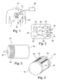
- the Figure 15 represents a second embodiment of a capsule according to the invention, in which the mobile element 42 'of actuation comprises a flat rigid surface 44 coupled to the body 40 of the capsule by an elastically deformable member 46 'of connection formed in the form of peripheral corrugations around the rigid surface 44.
- the Figure 16 represents a third embodiment, with a movable element 42 "of actuation consisting of a flexible stretch membrane 46" fixed to the body 40 of the capsule at its periphery and carrying at its center the rod 48 of connection to the transducer 50 of recovery energy.
Description
L'invention concerne, de façon générale, le domaine des "dispositifs médicaux actifs" tels que définis par la directive 93/42/CE du 14 juin 1993 du Conseil des communautés européennes, et notamment les "dispositifs médicaux implantables actifs" tels que définis par la directive du Conseil 90/385/CEE du 20 juin 1990.The invention relates generally to the field of "active medical devices" as defined by the Council of European Communities Directive 93/42 / EC of 14 June 1993, and in particular "active implantable medical devices" as defined by Council Directive 90/385 / EEC of 20 June 1990.
Cette définition inclut en particulier les appareils chargés de surveiller l'activité cardiaque et de générer des impulsions de stimulation, de resynchronisation et/ou de défibrillation en cas de trouble du rythme détecté par l'appareil. Elle inclut aussi les appareils neurologiques, les implants cochléaires, etc., ainsi que les dispositifs de mesure de pH ou encore d'impédance intracorporelle, telle que mesure d'impédance transpulmonaire ou d'impédance intracardiaque.This definition includes, in particular, devices for monitoring cardiac activity and generating pacing, resynchronization and / or defibrillation pulses in the event of a rhythm disorder detected by the device. It also includes neurological devices, cochlear implants, etc., as well as devices for measuring pH or intracorporeal impedance, such as measurement of transpulmonary impedance or intracardiac impedance.
L'invention concerne plus particulièrement ceux de ces dispositifs qui mettent en oeuvre des capsules autonomes implantées et dépourvues de toute liaison physique à un dispositif principal implanté, tel qu'un boîtier de générateur d'impulsions de stimulation.The invention relates more particularly to those devices which implement implanted autonomous capsules and devoid of any physical connection to an implanted main device, such as a stimulation pulse generator box.
Ces capsules autonomes sont dénommées pour cette raison "capsules leadless", pour les distinguer des électrodes ou des capteurs disposés à l'extrémité distale d'une sonde (lead), cette sonde étant parcourue sur toute sa longueur par un ou plusieurs conducteurs reliant par voie galvanique l'électrode ou le capteur à un générateur connecté à l'extrémité opposée, proximale, de la sonde.These autonomous capsules are named for this reason " leadless capsules ", to distinguish them from the electrodes or sensors arranged at the distal end of a probe ( lead ), this probe being traversed along its length by one or more connecting conductors by Galvanically route the electrode or sensor to a generator connected to the opposite, proximal end of the probe.
De telles capsules leadless sont par exemple décrites dans les
Ces capsules leadless peuvent être par exemple des capsules épicardiques, fixées à la paroi extérieure du coeur, ou bien des capsules endocavitaires, fixées à la paroi intérieure d'une cavité ventriculaire ou auriculaire au moyen d'une vis d'ancrage saillante, prolongeant axialement le corps de la capsule et destinée à pénétrer dans le tissu cardiaque par vissage au site d'implantation.These leadless capsules may for example be epicardial capsules, attached to the outer wall of the heart, or endocardial capsules, attached to the inner wall of a ventricular or atrial cavity by means of a projecting anchoring screw, extending axially. the body of the capsule and intended to penetrate into the heart tissue by screwing to the implantation site.
Une telle capsule comprend des circuits de détection/stimulation pour recueillir des potentiels de dépolarisation du myocarde et/ou pour appliquer des impulsions de stimulation au site où est implantée la capsule. La capsule porte alors une électrode appropriée qui peut être notamment constituée par une partie active de la vis d'ancrage.Such a capsule includes detection / stimulation circuits to collect myocardial depolarization potentials and / or to apply stimulation pulses to the site where the capsule is implanted. The capsule then carries a suitable electrode which may in particular be constituted by an active portion of the anchor screw.
Elle peut également incorporer, en variante ou en complément, un ou plusieurs capteurs permettant de mesurer localement la valeur d'un paramètre tel que le niveau d'oxygène dans le sang, la pression cardiaque endocavitaire, l'accélération de la paroi cardiaque, l'accélération du patient comme indicateur de l'activité, etc. Bien entendu, les capsules leadless incorporent également des moyens émetteurs/récepteurs de communication sans fil pour l'échange de données à distance.It may also incorporate, in a variant or in addition, one or more sensors making it possible to locally measure the value of a parameter such as the level of oxygen in the blood, the endocavitary cardiac pressure, the acceleration of the cardiac wall, the patient acceleration as an indicator of activity, etc. Of course, the leadless capsules also incorporate wireless communication transmitter / receiver means for remote data exchange.
L'invention n'est toutefois pas limitée à un type particulier de capsule, et elle est applicable indifféremment à tout type de capsule leadless, quelle que soit sa destination fonctionnelle.The invention is however not limited to a particular type of capsule, and it is applicable regardless of any type of leadless capsule , regardless of its functional purpose.
Quelle que soit la technique mise en oeuvre, le traitement des signaux au sein de la capsule et leur transmission à distance nécessite une énergie non négligeable par rapport aux ressources énergétiques que peut stocker cette capsule. Or, compte tenu de son caractère autonome, la capsule ne peut faire appel qu'à ses ressources propres telles qu'un circuit de récupération d'énergie du mouvement de la capsule, associé à une petite batterie tampon intégrée.Whatever the technique used, the processing of signals within the capsule and their remote transmission requires a significant energy compared to the energy resources that can store this capsule. However, given its autonomous nature, the capsule can only appeal to its own resources such as a capsule movement energy recovery circuit, associated with a small integrated buffer battery.
La gestion de l'énergie disponible est donc un point crucial pour le développement des techniques de capsules autonomes leadless, en particulier leur aptitude à disposer d'un système d'auto-alimentation intégré.The management of available energy is therefore a crucial point for the development of leadless autonomous capsule techniques, in particular their ability to have an integrated self-feeding system.
De nombreuses techniques de récupération d'énergie ont été proposées, adaptées à des implants autonomes de type leadless. Many energy recovery techniques have been proposed, adapted to leadless autonomous implants .
Un grand nombre de récupérateurs d'énergie actuels sont basés sur un dispositif inertiel, c'est-à-dire qui récupère l'accélération du milieu ambiant pour agir sur une masse, dite "masse sismique", dont le déplacement relatif génère de l'électricité par l'intermédiaire d'un transducteur piézoélectrique, électromagnétique, ou électrostatique. La puissance récupérée dépend principalement de la fréquence d'excitation, de son amplitude, et de la masse inertielle. Si le spectre de l'excitation est centré sur une fréquence spécifique fixe, le récupérateur peut être conçu pour résonner à la même fréquence et bénéficier ainsi d'une amplification mécanique pour récupérer un maximum de l'énergie inertielle, mais reste limité par la course de la masse. C'est pourquoi les récupérateurs inertiels habituels sont performants uniquement pour des applications à des fréquences élevées stables et à petites amplitudes, dans le domaine industriel par exemple.A large number of current energy recuperators are based on an inertial device, that is to say that recovers the acceleration of the ambient medium to act on a mass, called "seismic mass", the relative displacement of which generates electricity through a piezoelectric, electromagnetic, or electrostatic transducer. The recovered power depends mainly on the excitation frequency, its amplitude, and the inertial mass. If the spectrum of the excitation is centered on a fixed specific frequency, the recuperator can be designed to resonate at the same frequency and thus benefit from a mechanical amplification to recover a maximum of the inertial energy, but remains limited by the race of the mass. That's why the usual inertial recuperators are effective only for applications at stable high frequencies and small amplitudes, in the industrial field for example.
Dans le cas de l'environnement du corps humain, les excitations proviennent de l'accélération du corps ou des organes. Elles n'ont pas de fréquences spécifiques stables pour lesquelles le récupérateur d'énergie peut être optimisé de manière résonante, et ces fréquences sont très basses, inférieures à 10Hz, ce qui génère de grands déplacements et n'est pas adapté à la miniaturisation. Les générateurs existants miniaturisés adaptés au corps humain ne sont donc pas résonants, et ne peuvent générer une densité de puissance supérieure à celle des piles actuelles. Certains dispositifs non inertiels tentent de récupérer non pas l'accélération du corps ou des organes, mais leur déplacement. C'est le cas des systèmes de montres à remontage automatique qui, montés par exemple sur un implant cardiaque, restent trop volumineux et ne fournissent pas assez d'énergie, ou du cas spécifique des générateurs piézoélectriques montés sous les talons, fournissant une grande puissance mais aux dimensions macroscopiques.In the case of the environment of the human body, the excitations come from the acceleration of the body or organs. They have no stable specific frequencies for which the energy recuperator can be resonantly optimized, and these frequencies are very low, less than 10 Hz, which generates large displacements and is not suitable for miniaturization. The miniaturized existing generators adapted to the human body are therefore not resonant, and can not generate a higher power density than current batteries. Some non-inertial devices attempt to recover not the acceleration of the body or organs, but their displacement. This is the case of self-winding watch systems that, for example, mounted on a cardiac implant, remain too large and do not provide enough energy, or the specific case of piezoelectric generators mounted under the heels, providing great power but with macroscopic dimensions.
Une technique alternative de récupération d'énergie pour les implants en milieu fluidique et notamment en milieu sanguin consiste à récupérer les variations de pression du fluide par une membrane flexible dont la déformation ou le mouvement peut générer de l'électricité via un transducteur. Plusieurs méthodes de transduction ont été proposées comme l'entraînement d'un rotor, produisant de l'électricité électromagnétique à la manière d'un alternateur classique. La complexité de l'agencement des pièces nécessaires à un tel système en limite largement la miniaturisation. En outre, ce type de transducteur, de part de sa nature magnétique, n'est pas compatible avec les systèmes d'imagerie par résonance magnétique (IRM).An alternative energy recovery technique for implants in a fluid medium and in particular in the blood medium consists in recovering fluid pressure variations by a flexible membrane whose deformation or movement can generate electricity via a transducer. Several transduction methods have been proposed such as driving a rotor, producing electromagnetic electricity in the manner of a conventional alternator. The complexity of the arrangement of the parts necessary for such a system largely limits the miniaturization. In addition, this type of transducer, because of its magnetic nature, is not compatible with magnetic resonance imaging (MRI) systems.
Il a été également proposé, en plus d'un récupérateur inertiel classique basé sur le mouvement de la paroi cardiaque, un récupérateur des efforts de pression subis dans une cavité cardiaque, où la membrane flexible entraîne un générateur résonant à une plus grande fréquence que la fréquence d'excitation. Le fait que le générateur soit résonant à haute fréquence permet de récupérer une large partie de l'énergie mécanique apportée par la membrane, mais la conversion de fréquence pose des problèmes soit de fiabilité mécanique, soit de compatibilité IRM en cas de couplage par aimants. De plus, les vibrations à haute fréquence multiplient le nombre de cycles, ce qui peut s'avérer critique pour la fatigue mécanique des systèmes.It has also been proposed, in addition to a conventional inertial recuperator based on the movement of the cardiac wall, a recuperator of the pressure forces undergone in a heart chamber, where the flexible membrane drives a resonant generator at a greater frequency than the excitation frequency. The fact that the generator is resonant at high frequency makes it possible to recover a large part of the mechanical energy supplied. by the membrane, but the frequency conversion poses problems of mechanical reliability or MRI compatibility in the case of coupling by magnets. In addition, high frequency vibrations increase the number of cycles, which can be critical for mechanical fatigue of the systems.
Dans
Le
Le but de l'invention est de proposer un générateur d'alimentation électrique pour une capsule autonome implantable et entièrement immergeable dans un fluide corporel soumis à des variations régulières de pression, qui pallie les inconvénients ci-dessus et réponde aux impératifs de:
- récupération optimale de l'énergie induite par les variations de pression du fluide corporel ;
- miniaturisation : compatibilité avec le volume extrêmement réduit (quelques millimètres cubes) d'un implant leadless ;
- fiabilité : garantie de fonctionnement sur plusieurs années de durée de vie de l'implant ;
- insensibilité aux phénomènes magnétiques : notamment pour assurer la compatibilité IRM qui est aujourd'hui requise pour les dispositifs implantés ; et
- biocompatibilité : absence d'éléments extérieurs risquant de provoquer des réactions inflammatoires.
- optimal recovery of the energy induced by the variations of pressure of the body fluid;
- miniaturization: compatibility with the extremely small volume (a few cubic millimeters) of a leadless implant;
- reliability: guaranteed operation over several years of implant life;
- insensitivity to magnetic phenomena: in particular to ensure the MRI compatibility that is required for implanted devices today; and
- biocompatibility: absence of external elements that may cause inflammatory reactions.
Essentiellement, l'invention propose un système d'alimentation par récupération d'énergie incorporé à une capsule implantable dont le corps de boîtier possède un élément déformable sous l'effet des variations de pression du milieu environnant, typiquement les variations de pression du sang au cours du cycle cardiaque. La déformation de cet élément est transmise à un transducteur piézoélectrique convertissant directement l'énergie mécanique de déformation en énergie électrique qui est ensuite délivrée à un module de gestion électrique et de stockage alimentant la capsule en énergie.Essentially, the invention proposes an energy recovery power system incorporated in an implantable capsule whose housing body has a deformable element under the effect of pressure variations of the surrounding medium, typically the pressure variations of the blood at course of the cardiac cycle. The deformation of this element is transmitted to a piezoelectric transducer which directly converts the mechanical energy of deformation into electrical energy which is then delivered to an electrical management and storage module supplying the capsule with energy.
On notera que le système n'a besoin ni d'être résonant ni de contenir des éléments magnétiques.Note that the system does not need to be resonant or contain magnetic elements.
Plus précisément, la capsule intracorporelle autonome est d'un type général tel que celui divulgué par le
De façon caractéristique de l'invention, l'élément mobile d'actionnement comprend une surface rigide couplée au composant piézoélectrique et un soufflet élastiquement déformable de liaison de cette surface rigide au reste du corps.In a characteristic manner of the invention, the mobile actuating element comprises a rigid surface coupled to the piezoelectric component and an elastically deformable bellows for connecting this rigid surface to the rest of the body.
Ainsi, l'invention consiste en une capsule intracorporelle autonome comprenant un récupérateur d'énergie possédant un élément mobile d'actionnement susceptible de se déformer et/ou de se déplacer par rapport au corps rigide et fixe de la capsule. Lorsque que cette dernière est placée dans une cavité cardiaque ou en milieu sanguin, la pression sanguine va s'appliquer sur le corps et l'élément mobile : du fait des variations de pression au cours du cycle cardiaque, l'élément mobile de la capsule va être soumis à des forces variables au cours du temps, et, compte tenu de sa souplesse, va se déformer ou se déplacer suivant le cycle des variations de pression, emmagasinant ainsi de l'énergie mécanique.Thus, the invention consists of an autonomous intracorporeal capsule comprising an energy recuperator having a movable actuating element capable of deforming and / or moving relative to the rigid and fixed body of the capsule. When the latter is placed in a heart chamber or in a blood medium, the blood pressure will be applied to the body and the movable element: due to pressure variations during the cardiac cycle, the mobile element of the capsule will be subjected to variable forces over time, and, given its flexibility, will deform or move according to the cycle of pressure variations, thus storing mechanical energy.
Cette énergie mécanique est transformée en électricité par un transducteur piézoélectrique fixé d'une part à une partie fixe du corps, et d'autre part à l'élément mobile d'actionnement. Le transducteur est ainsi également assujetti à des déformations mécaniques qu'il convertit en énergie électrique par effet piézoélectrique direct. Ce composant piézoélectrique fonctionne donc en régime forcé non résonant à la même fréquence que les variations de pression externe, il n'est donc pas soumis aux contraintes de conversion de fréquence ou de présence de masse sismique, en plus de réduire le nombre de cycles de fonctionnement.This mechanical energy is converted into electricity by a piezoelectric transducer fixed on the one hand to a fixed part of the body, and on the other hand to the movable actuating element. The transducer is thus also subject to mechanical deformations that it converts into electrical energy by direct piezoelectric effect. This piezoelectric component therefore operates in non-resonant forced mode at the same frequency as the external pressure variations, it is therefore not subjected to frequency conversion or seismic mass presence constraints, in addition to reducing the number of cycles of operation.
Le composant piézoélectrique est avantageusement structuré en bandes afin de réduire sa raideur et augmenter sa déformation pour une meilleure récupération d'énergie. La structure de base est une bande longue et fine, formant une poutre encastrée à une extrémité et libre l'autre extrémité soumise à la sollicitation extérieure.The piezoelectric component is advantageously structured in strips to reduce its stiffness and increase its deformation for better energy recovery. The basic structure is a long strip and thin, forming a beam embedded at one end and free the other end subjected to external stress.
Outre la forme rectiligne, l'invention propose un certain nombre de dispositions avantageuses visant à augmenter la longueur de la structure en bandes du composant piézoélectrique tout en conservant une surface réduite.In addition to the rectilinear shape, the invention proposes a number of advantageous arrangements for increasing the length of the band structure of the piezoelectric component while maintaining a reduced surface area.
Il est prévu notamment que la bande piézoélectrique est enroulée en spirale ou formée de segments rectilignes repliés ou encore qu'elle a une structure annulaire.In particular, it is provided that the piezoelectric strip is spirally wound or formed of folded rectilinear segments or that it has an annular structure.
De même, au niveau de la structure du composant piézoélectrique lui-même et de manière à ajuster au mieux la raideur du système tout en gardant un système compact, le composant piézoélectrique comprend avantageusement deux bandes piézoélectriques en parallèle autour d'un point d'application commun. Le composant piézoélectrique peut également présenter une pluralité de structures de bandes disposées en parallèle. Enfin, la capsule selon l'invention peut comporter une pluralité de composants piézoélectriques disposés en série ou en parallèleSimilarly, at the level of the structure of the piezoelectric component itself and in order to adjust the stiffness of the system while keeping a compact system, the piezoelectric component advantageously comprises two piezoelectric strips in parallel around a point of application. common. The piezoelectric component may also have a plurality of band structures arranged in parallel. Finally, the capsule according to the invention may comprise a plurality of piezoelectric components arranged in series or in parallel
On va maintenant décrire divers exemples de mise en oeuvre de l'invention, en référence aux dessins annexés où les mêmes références numériques désignent d'une figure à l'autre des éléments identiques ou fonctionnellement semblables.
- La
Figure 1 est un schéma d'un ensemble de dispositifs médicaux comprenant des capsules leadless, implantées au sein du corps d'un patient. - La
Figure 2 est un schéma par blocs fonctionnels montrant les différents circuits électroniques d'une capsule leadless. - La
Figure 3 est une vue en perspective d'un premier mode de réalisation du corps d'une capsule implantable selon l'invention. - La
Figure 4 est une vue en perspective d'un deuxième mode de réalisation du corps d'une capsule implantable selon l'invention. - La
Figure 5a est une vue en coupe d'un transducteur piézoélectrique au repos d'une capsule implantable selon l'invention. - La
Figure 5b est une vue du transducteur de laFigure 5a en fonctionnement. - La
Figure 5c est une vue partielle en perspective du transducteur des Figures 5a et 5b. - Les
Figures 6a à 6c sont des vues de dessus de composants piézoélectriques formés de bandes rectilignes. - Les
Figures 7a et 7b sont des vues de dessus de composants piézoélectriques formés de bandes enroulées en spirale. - La
Figure 8 est une vue de dessus d'un composant piézoélectrique de structure annulaire. - Les
Figures 9a à 9c sont des vues en perspective de différentes structures de bandes piézoélectriques rectilignes. - Les
Figures 10a à 10c sont des vues en perspective de différentes structures d'électrodes pour des bandes piézoélectriques unimorphes. - Les
Figures 11a à 11c sont des vues en perspective de différentes structures d'électrodes pour des bandes piézoélectriques bimorphes. - Les
Figures 12a et 12b sont des vues en coupe montrant respectivement des configurations série et parallèle d'électrodes de la structure de la Figure 11a. - Les
Figures 13a et 13b sont des vues en perspective montrant des transducteurs piézoélectriques constitués respectivement de composants piézoélectriques rectilignes et spiralés en série. - Les
Figures 14a et 14b sont des vues en perspective montrant des transducteurs piézoélectriques constitués respectivement de composants piézoélectriques rectilignes et spiralés en parallèles. - La
Figure 15 est une vue en coupe d'une première variante du transducteur de laFigure 5a . - La
Figure 16 est une vue en coupe d'une deuxième variante du transducteur de laFigure 5a . - La
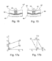
Figure 17a est un exemple de diagramme force F-déplacement u du cycle de fonctionnement d'une capsule implantable conforme à l'invention. - La
Figure 17b est un exemple de diagramme tension V-charge Q du cycle de fonctionnement d'une capsule implantable conforme à l'invention.
- The
Figure 1 is a diagram of a set of medical devices including leadless capsules , implanted within the body of a patient. - The
Figure 2 is a functional block diagram showing the different electronic circuits of a leadless capsule . - The
Figure 3 is a perspective view of a first embodiment of the body of an implantable capsule according to the invention. - The
Figure 4 is a perspective view of a second embodiment of the body of an implantable capsule according to the invention. - The
Figure 5a is a sectional view of a piezoelectric transducer at rest of an implantable capsule according to the invention. - The
Figure 5b is a view of the transducer from theFigure 5a Operating. - The
Figure 5c is a partial perspective view of the transducer of Figures 5a and 5b. - The
Figures 6a to 6c are top views of piezoelectric components formed of straight strips. - The
Figures 7a and 7b are top views of piezoelectric components formed of spirally wound strips. - The
Figure 8 is a top view of a piezoelectric component of annular structure. - The
Figures 9a to 9c are perspective views of different straight piezoelectric strip structures. - The
Figures 10a to 10c are perspective views of different electrode structures for unimorphous piezoelectric bands. - The
Figures 11a to 11c are perspective views of different electrode structures for bimorphous piezoelectric strips. - The
Figures 12a and 12b are sectional views respectively showing serial and parallel configurations of electrodes of the structure of Figure 11a. - The
Figures 13a and 13b are perspective views showing piezoelectric transducers consisting respectively of linear and spiral piezoelectric components in series. - The
Figures 14a and 14b are perspective views showing piezoelectric transducers consisting of straight and parallel spiral piezoelectric components, respectively. - The
Figure 15 is a sectional view of a first variant of the transducer of theFigure 5a . - The
Figure 16 is a sectional view of a second variant of the transducer of theFigure 5a . - The
Figure 17a is an example of a F-displacement force diagram u of the operating cycle of an implantable capsule according to the invention. - The
Figure 17b is an example of a voltage diagram V -load Q of the operating cycle of an implantable capsule according to the invention.
On va maintenant décrire divers exemples de réalisation du transducteur de récupération d'énergie selon l'invention.Various embodiments of the energy recovery transducer according to the invention will now be described.
Sur la
Celui-ci est équipé par exemple d'un implant 10 tel qu'un défibrillateur/ stimulateur/resynchroniseur implanté, un défibrillateur sous-cutané ou encore un enregistreur longue durée. Ce dispositif 10 est le dispositif maître d'un réseau comportant une pluralité de dispositifs esclaves 12 à 18, qui peuvent notamment inclure des capsules intracardiaques 12 ou épicardiques 14 implantées directement sur le coeur du patient, d'autres dispositifs 16 tels que capteurs de myopotentiels ou dispositifs de stimulation neurologique, et éventuellement un dispositif externe 18 disposé sur un brassard et pourvu d'électrodes en contact avec la peau. Le dispositif 10 peut également être utilisé en tant que passerelle avec le monde extérieur pour communiquer avec un périphérique externe 20 du type programmateur ou dispositif de télétransmission de données avec lequel il pourra communiquer par télémétrie.This is equipped for example with an
La
La capsule comporte par exemple un couple d'électrodes 22, 24 reliées à un circuit 26 générateur d'impulsions de stimulation (pour une capsule active incorporant cette fonction) et/ou à un circuit de détection 28 servant au recueil des potentiels de dépolarisation recueillis entre les électrodes 22 et 24. Un circuit central 30 inclut l'ensemble de l'électronique permettant de piloter les diverses fonctions de la capsule, la mémorisation des signaux recueillis, etc. Il comprend un microcontrôleur et un oscillateur générant les signaux d'horloge nécessaires au fonctionnement du microcontrôleur et à la communication. Il peut également contenir un convertisseur analogique/numérique et une mémoire de stockage numérique. La capsule peut également être pourvue d'un capteur 32 tel qu'un capteur d'accélération, de pression, un capteur hémodynamique, de température, de saturation en oxygène, etc. La capsule comprend un étage de récupération d'énergie 34 alimentant l'ensemble des circuits via un étage de gestion d'énergie 36. Les électrodes 22 et 24 sont également reliées à un circuit d'émission/réception d'impulsions 38 servant à la communication sans fil avec le dispositif maître ou les autres capsules.The capsule comprises, for example, a pair of
L'invention concerne plus particulièrement l'étage de récupération d'énergie 34 qui, de façon caractéristique, utilise les variations de pression du milieu environnant, notamment les variations cycliques de la pression sanguine, pour déformer un matériau piézoélectrique. La récupération d'énergie est obtenue grâce à la création de charges électriques résultant des contraintes mécaniques de déformation appliquées au matériau piézoélectrique sous l'effet des variations de pression sanguine.The invention more particularly relates to the
Pour pouvoir prendre en compte ces déformations, la capsule est réalisée sous forme d'un corps 40 pourvu, comme illustré
Dans l'exemple de la
Dans l'exemple de la
Dans l'un ou l'autre cas, le corps 40 avec son élément déformable 42 sont avantageusement réalisés sous forme monobloc, par exemple en titane évaporé ou électrodéposé sur un mandrin soluble.In either case, the
Sur l'exemple de réalisation des
D'une manière générale, l'énergie mécanique en entrée est due à la force de pression sanguine de faible intensité, à savoir quelques dizaines à quelques centaines de mN pour un grand déplacement, de l'ordre de quelques centaines de µm. Cela implique que la raideur du système doit être faible, typiquement quelques centaines à quelques milliers de mN/m. Or ce genre de raideur est très difficile à obtenir avec des éléments piézoélectriques standard tels que ceux décrits dans l'article de l'état de la technique précité.In general, the input mechanical energy is due to the low intensity blood pressure force, namely a few tens to a few hundreds of mN for a large displacement, of the order of a few hundred microns. This implies that the stiffness of the system must be low, typically a few hundred to a few thousand mN / m. However, this kind of stiffness is very difficult to obtain with standard piezoelectric elements such as those described in the article of the state of the art mentioned above.
Pour répondre à ces critères de souplesse et dimensions, tout en restant compatible avec l'exigence de miniaturisation, il est proposé que les composants piézoélectriques constituant les transducteurs d'énergie mis en oeuvre dans des capsules conformes à l'invention présentent une structure comprenant au moins une bande qui, à l'image de la bande 53 de la
Les couches piézoélectriques 82a, 82b peuvent être réalisées en un matériau comme la céramique PZT ou des monocristaux de type PMN-PT, titanate de baryum ou niobate de lithium présentant un fort couplage électromécanique.The
Sur la
Selon le mode de réalisation de la
Les
On va maintenant décrire en regard des
De la position ① à la position ②, le circuit est ouvert et la force appliquée F croît jusqu'à F0. Lors de cette phase, la charge Q reste nulle et la tension V passe de 0 à V2.From position ① to
De la position ② à la position ③, sous la force F0, on ferme le circuit en récupérant les charges accumulées. En ③, on a donc Q = Q3. Le circuit est ensuite réouvert.From the
De la position ③ à la position ④, la force F revient à 0 et la charge reste constante, à Q3. En ④, V4 = -V2.From
De la position ④ à la position ①, on ferme le circuit en récupérant une deuxième fois la charge.From
L'énergie récupérée par cycle est donc W = V2Q3.The energy recovered per cycle is therefore W = V 2 Q 3 .
D'autre cycles de conversion sont également possibles, comme par exemple un cycle à une seule extraction de charge (passant directement de l'étape ③ à l'étape ①), ou par exemple un cycle où la tension est imposée aux bornes de la couche piézoélectrique pour optimiser l'extraction de l'énergie.Other conversion cycles are also possible, such as for example a cycle with a single charge extraction (going directly from
La
Sur la
Les
Les bandes des composants 52', 52" des
Le composant piézoélectrique 52' de la
Le composant piézoélectrique 52" de la
Le composant piézoélectrique 62 de la
De même, le composant piézoélectrique 62' de la
En outre, il est critique dans le cas d'un récupérateur d'énergie piézoélectrique de limiter les contraintes mécaniques pour avoir un système fiable, sans fatigue sur un grand nombre de cycles, typiquement à moins de quelques dizaines de MPa pour un matériau de type PZT, et de limiter la tension aux bornes du composant piézoélectrique afin de la rendre compatible avec des systèmes électroniques classiques, c'est à dire moins de 15 ou 20 V.In addition, it is critical in the case of a piezoelectric energy recuperator to limit the mechanical stresses to have a reliable system, without fatigue over a large number of cycles, typically less than a few tens of MPa for a type of material. PZT, and limit the voltage across the piezoelectric component to make it compatible with conventional electronic systems, ie less than 15 or 20 V.
Dans ce but, il est proposé de réaliser les transducteurs de récupération en agençant en série et en parallèle plusieurs composants piézoélectriques, par exemple de type poutre ou spirale. En effet, pour une énergie mécanique en entrée donnée par une force et un déplacement, mettre des structures en série va réduire les déformations de chaque élément et ainsi réduire les contraintes mécaniques, et mettre des structures en parallèle permet de diminuer l'épaisseur des composants piézoélectriques pour abaisser la tension à champ électrique constant dans le matériau. Les
De même, les
La
La
Claims (15)
- An autonomous intracorporeal capsule, including a body (40) and, inside this body, electronic circuits (26-36) and electric supply means devoid of seismic mass, comprising:- an energy harvesting transducer (50), adapted to convert an external physical stress (F) applied to the capsule into an electrical quantity, this transducer comprising at least one piezoelectric component (52) coupled to a mobile operating element (42) receiving said external physical stress,
this piezoelectric component (52) having at least one structure with at least one piezoelectric band (521a, 521b) fixed to the body (40) of the capsule at one end (54) and adapted to be subjected to an external physical stress (F) at an application point (A) located at another end (56); and- an energy storage and management module (36), supplied by the energy harvesting transducer (50) under the effect of a deformation of the piezoelectric component (52) due to the external physical stress (F) transmitted by the mobile operating element (42),
characterized in that the mobile operating element (42) comprises a rigid surface (44) coupled to the piezoelectric component and an elastically deformable bellows (46) for the connection of this rigid surface to the remaining of the body (40). - The capsule of claim 1, wherein the piezoelectric band (521a, 521b) is rectilinear in shape.
- The capsule of claim 1, wherein the piezoelectric band (621a, 621b) is wound into a spiral.
- The capsule of claim 1, wherein the piezoelectric band (521'a, 521'b) is formed of folded rectilinear segments.
- The capsule of claim 1, wherein the piezoelectric band (721a, 721b) has an annular structure.
- The capsule of claim 1, wherein the piezoelectric component (52; 52'; 62) comprises two piezoelectric bands in parallel about a common point of application (A).
- The capsule of claim 6, wherein the piezoelectric component (52"; 62') has a plurality of band structures arranged in parallel.
- The capsule of claim 1, wherein the energy harvesting transducer (50'a; 50'b) includes a plurality of piezoelectric components (52; 62) arranged in series.
- The capsule of claim 1, wherein the energy harvesting transducer (50"a; 50"b) includes a plurality of piezoelectric components (52; 62) arranged in parallel.
- The capsule of claim 1, wherein the piezoelectric band (521a, 521b) is formed of a substrate (80), at least one layer (82a, 82b) of piezoelectric material deposited on a face of the substrate and at least one electrode (84a, 84b) covering at least partially the layer of piezoelectric material.
- The capsule of claim 10, wherein a layer (82) of piezoelectric material is deposited on one face of the substrate (80).
- The capsule of claim 10, wherein a layer (82a, 82b) of piezoelectric material is deposited on each face of the substrate (80).
- The capsule of claim 10, wherein the electrode (84; 84a, 84b) covers fully the layer (82; 82a, 82b) of piezoelectric material.
- The capsule of claim 10, wherein the at least one electrode (84'; 84'a, 84'b) covers partially the layer (82; 82a, 82b) of piezoelectric material.
- The capsule of claim 10, wherein the electrodes (84"; 84"a, 84"b) covering the layer (82; 82a, 82b) of piezoelectric material are interdigited.
Applications Claiming Priority (1)
| Application Number | Priority Date | Filing Date | Title |
|---|---|---|---|
| FR1252217 | 2012-03-12 |
Publications (2)
| Publication Number | Publication Date |
|---|---|
| EP2639845A1 EP2639845A1 (en) | 2013-09-18 |
| EP2639845B1 true EP2639845B1 (en) | 2014-11-19 |
Family
ID=47552925
Family Applications (1)
| Application Number | Title | Priority Date | Filing Date |
|---|---|---|---|
| EP13152208.8A Active EP2639845B1 (en) | 2012-03-12 | 2013-01-22 | Autonomous intracorporeal capsule with piezoelectric energy recovery |
Country Status (2)
| Country | Link |
|---|---|
| US (1) | US9364675B2 (en) |
| EP (1) | EP2639845B1 (en) |
Families Citing this family (102)
| Publication number | Priority date | Publication date | Assignee | Title |
|---|---|---|---|---|
| US9730790B2 (en) | 2009-09-29 | 2017-08-15 | Edwards Lifesciences Cardiaq Llc | Replacement valve and method |
| US9681951B2 (en) | 2013-03-14 | 2017-06-20 | Edwards Lifesciences Cardiaq Llc | Prosthesis with outer skirt and anchors |
| EP2857065B1 (en) * | 2013-10-01 | 2016-05-04 | Sorin CRM SAS | Autonomous intracorporeal capsule having energy recovery with frequency conversion |
| EP2857064B1 (en) | 2013-10-01 | 2015-10-14 | Sorin CRM SAS | Autonomous intracorporeal capsule with energy recovery by piezoelectric transducer |
| US20150162523A1 (en) * | 2013-12-06 | 2015-06-11 | Murata Manufacturing Co., Ltd. | Piezoelectric device |
| CN104740714B (en) * | 2013-12-26 | 2018-08-28 | 中国人民解放军第二军医大学 | Implanted self energizing insulin pump |
| CN106102830B (en) | 2014-01-10 | 2019-07-16 | 心脏起搏器股份公司 | For improving the method and system of the communication between medical device |
| WO2015106015A1 (en) | 2014-01-10 | 2015-07-16 | Cardiac Pacemakers, Inc. | Systems and methods for detecting cardiac arrhythmias |
| FR3022760A1 (en) | 2014-06-25 | 2016-01-01 | Sorin Crm Sas | HYBRID ASSEMBLY FORMING ACTIVE IMPLANTABLE MEDICAL DEVICE |
| CN106537755B (en) | 2014-06-27 | 2019-06-11 | 音力发电株式会社 | Power generator |
| US10674928B2 (en) | 2014-07-17 | 2020-06-09 | Medtronic, Inc. | Leadless pacing system including sensing extension |
| US9399140B2 (en) | 2014-07-25 | 2016-07-26 | Medtronic, Inc. | Atrial contraction detection by a ventricular leadless pacing device for atrio-synchronous ventricular pacing |
| WO2016033197A2 (en) | 2014-08-28 | 2016-03-03 | Cardiac Pacemakers, Inc. | Medical device with triggered blanking period |
| US9492668B2 (en) | 2014-11-11 | 2016-11-15 | Medtronic, Inc. | Mode switching by a ventricular leadless pacing device |
| US9724519B2 (en) | 2014-11-11 | 2017-08-08 | Medtronic, Inc. | Ventricular leadless pacing device mode switching |
| US9492669B2 (en) | 2014-11-11 | 2016-11-15 | Medtronic, Inc. | Mode switching by a ventricular leadless pacing device |
| US9623234B2 (en) | 2014-11-11 | 2017-04-18 | Medtronic, Inc. | Leadless pacing device implantation |
| US9289612B1 (en) | 2014-12-11 | 2016-03-22 | Medtronic Inc. | Coordination of ventricular pacing in a leadless pacing system |
| ES2713231T3 (en) | 2015-02-06 | 2019-05-20 | Cardiac Pacemakers Inc | Systems for the safe supply of electrical stimulation therapy |
| JP6510660B2 (en) | 2015-02-06 | 2019-05-08 | カーディアック ペースメイカーズ, インコーポレイテッド | System and method for treating cardiac arrhythmias |
| US10046167B2 (en) | 2015-02-09 | 2018-08-14 | Cardiac Pacemakers, Inc. | Implantable medical device with radiopaque ID tag |
| DE202015100719U1 (en) * | 2015-02-13 | 2016-05-17 | Günter Beckmann | Electrostatic microgenerator and probe |
| US11285326B2 (en) | 2015-03-04 | 2022-03-29 | Cardiac Pacemakers, Inc. | Systems and methods for treating cardiac arrhythmias |
| US10050700B2 (en) | 2015-03-18 | 2018-08-14 | Cardiac Pacemakers, Inc. | Communications in a medical device system with temporal optimization |
| FR3033705A1 (en) | 2015-03-18 | 2016-09-23 | Sorin Crm Sas | ACTIVE IMPLANTABLE MEDICAL DEVICE COMPRISING A CONNECTOR-FREE CAPSULE CONNECTED PERMANENTLY TO A MICROSONDE |
| WO2016149262A1 (en) | 2015-03-18 | 2016-09-22 | Cardiac Pacemakers, Inc. | Communications in a medical device system with link quality assessment |
| US10357159B2 (en) | 2015-08-20 | 2019-07-23 | Cardiac Pacemakers, Inc | Systems and methods for communication between medical devices |
| EP3337558A1 (en) | 2015-08-20 | 2018-06-27 | Cardiac Pacemakers, Inc. | Systems and methods for communication between medical devices |
| US9956414B2 (en) | 2015-08-27 | 2018-05-01 | Cardiac Pacemakers, Inc. | Temporal configuration of a motion sensor in an implantable medical device |
| US9968787B2 (en) | 2015-08-27 | 2018-05-15 | Cardiac Pacemakers, Inc. | Spatial configuration of a motion sensor in an implantable medical device |
| WO2017040115A1 (en) | 2015-08-28 | 2017-03-09 | Cardiac Pacemakers, Inc. | System for detecting tamponade |
| US10226631B2 (en) | 2015-08-28 | 2019-03-12 | Cardiac Pacemakers, Inc. | Systems and methods for infarct detection |
| CN108136189B (en) | 2015-08-28 | 2021-10-15 | 心脏起搏器股份公司 | System for behavioral response signal detection and therapy delivery |
| WO2017044389A1 (en) | 2015-09-11 | 2017-03-16 | Cardiac Pacemakers, Inc. | Arrhythmia detection and confirmation |
| EP3359251B1 (en) | 2015-10-08 | 2019-08-07 | Cardiac Pacemakers, Inc. | Adjusting pacing rates in an implantable medical device |
| US20200254249A1 (en) | 2015-11-17 | 2020-08-13 | Inspire Medical Systems, Inc. | Microstimulation sleep disordered breathing (sdb) therapy device |
| EP3389775B1 (en) | 2015-12-17 | 2019-09-25 | Cardiac Pacemakers, Inc. | Conducted communication in a medical device system |
| US10905886B2 (en) | 2015-12-28 | 2021-02-02 | Cardiac Pacemakers, Inc. | Implantable medical device for deployment across the atrioventricular septum |
| WO2017127548A1 (en) | 2016-01-19 | 2017-07-27 | Cardiac Pacemakers, Inc. | Devices for wirelessly recharging a rechargeable battery of an implantable medical device |
| WO2017136548A1 (en) | 2016-02-04 | 2017-08-10 | Cardiac Pacemakers, Inc. | Delivery system with force sensor for leadless cardiac device |
| WO2017173275A1 (en) | 2016-03-31 | 2017-10-05 | Cardiac Pacemakers, Inc. | Implantable medical device with rechargeable battery |
| US10328272B2 (en) | 2016-05-10 | 2019-06-25 | Cardiac Pacemakers, Inc. | Retrievability for implantable medical devices |
| US10668294B2 (en) | 2016-05-10 | 2020-06-02 | Cardiac Pacemakers, Inc. | Leadless cardiac pacemaker configured for over the wire delivery |
| US10512784B2 (en) | 2016-06-27 | 2019-12-24 | Cardiac Pacemakers, Inc. | Cardiac therapy system using subcutaneously sensed P-waves for resynchronization pacing management |
| WO2018009569A1 (en) | 2016-07-06 | 2018-01-11 | Cardiac Pacemakers, Inc. | Method and system for determining an atrial contraction timing fiducial in a leadless cardiac pacemaker system |
| US10426962B2 (en) | 2016-07-07 | 2019-10-01 | Cardiac Pacemakers, Inc. | Leadless pacemaker using pressure measurements for pacing capture verification |
| RU169922U1 (en) * | 2016-07-12 | 2017-04-06 | федеральное государственное автономное образовательное учреждение высшего образования "Санкт-Петербургский политехнический университет Петра Великого" (ФГАОУ ВО "СПбПУ") | ENERGY DEVICE FOR IMPLANTED MEDICAL DEVICES |
| WO2018017226A1 (en) | 2016-07-20 | 2018-01-25 | Cardiac Pacemakers, Inc. | System for utilizing an atrial contraction timing fiducial in a leadless cardiac pacemaker system |
| WO2018035343A1 (en) | 2016-08-19 | 2018-02-22 | Cardiac Pacemakers, Inc. | Trans septal implantable medical device |
| US10243136B2 (en) * | 2016-08-22 | 2019-03-26 | Masoud Ghanbari | Piezoelectric energy harvesting system from vehicle's tires |
| EP3503970B1 (en) | 2016-08-24 | 2023-01-04 | Cardiac Pacemakers, Inc. | Cardiac resynchronization using fusion promotion for timing management |
| CN109640809B (en) | 2016-08-24 | 2021-08-17 | 心脏起搏器股份公司 | Integrated multi-device cardiac resynchronization therapy using P-wave to pacing timing |
| WO2018057626A1 (en) | 2016-09-21 | 2018-03-29 | Cardiac Pacemakers, Inc. | Implantable cardiac monitor |
| US10758737B2 (en) | 2016-09-21 | 2020-09-01 | Cardiac Pacemakers, Inc. | Using sensor data from an intracardially implanted medical device to influence operation of an extracardially implantable cardioverter |
| US10905889B2 (en) | 2016-09-21 | 2021-02-02 | Cardiac Pacemakers, Inc. | Leadless stimulation device with a housing that houses internal components of the leadless stimulation device and functions as the battery case and a terminal of an internal battery |
| US10561330B2 (en) | 2016-10-27 | 2020-02-18 | Cardiac Pacemakers, Inc. | Implantable medical device having a sense channel with performance adjustment |
| US10413733B2 (en) | 2016-10-27 | 2019-09-17 | Cardiac Pacemakers, Inc. | Implantable medical device with gyroscope |
| US10765871B2 (en) | 2016-10-27 | 2020-09-08 | Cardiac Pacemakers, Inc. | Implantable medical device with pressure sensor |
| EP3532159B1 (en) | 2016-10-27 | 2021-12-22 | Cardiac Pacemakers, Inc. | Implantable medical device delivery system with integrated sensor |
| WO2018081237A1 (en) | 2016-10-27 | 2018-05-03 | Cardiac Pacemakers, Inc. | Use of a separate device in managing the pace pulse energy of a cardiac pacemaker |
| US10463305B2 (en) | 2016-10-27 | 2019-11-05 | Cardiac Pacemakers, Inc. | Multi-device cardiac resynchronization therapy with timing enhancements |
| CN109890456B (en) | 2016-10-31 | 2023-06-13 | 心脏起搏器股份公司 | System for activity level pacing |
| JP6843235B2 (en) | 2016-10-31 | 2021-03-17 | カーディアック ペースメイカーズ, インコーポレイテッド | Systems and methods for activity level pacing |
| WO2018089311A1 (en) | 2016-11-08 | 2018-05-17 | Cardiac Pacemakers, Inc | Implantable medical device for atrial deployment |
| US10632313B2 (en) | 2016-11-09 | 2020-04-28 | Cardiac Pacemakers, Inc. | Systems, devices, and methods for setting cardiac pacing pulse parameters for a cardiac pacing device |
| US10894163B2 (en) | 2016-11-21 | 2021-01-19 | Cardiac Pacemakers, Inc. | LCP based predictive timing for cardiac resynchronization |
| US10639486B2 (en) | 2016-11-21 | 2020-05-05 | Cardiac Pacemakers, Inc. | Implantable medical device with recharge coil |
| CN109996585B (en) | 2016-11-21 | 2023-06-13 | 心脏起搏器股份公司 | Implantable medical device with magnetically permeable housing and induction coil disposed around the housing |
| US10881863B2 (en) | 2016-11-21 | 2021-01-05 | Cardiac Pacemakers, Inc. | Leadless cardiac pacemaker with multimode communication |
| US10881869B2 (en) | 2016-11-21 | 2021-01-05 | Cardiac Pacemakers, Inc. | Wireless re-charge of an implantable medical device |
| US11389657B2 (en) | 2016-12-30 | 2022-07-19 | Sorin Crm Sas | Autonomous implantable capsule for heart stimulation |
| US11207532B2 (en) | 2017-01-04 | 2021-12-28 | Cardiac Pacemakers, Inc. | Dynamic sensing updates using postural input in a multiple device cardiac rhythm management system |
| CN110234392B (en) | 2017-01-26 | 2023-08-11 | 心脏起搏器股份公司 | Leadless device with overmolded component |
| EP3573708B1 (en) | 2017-01-26 | 2021-03-10 | Cardiac Pacemakers, Inc. | Leadless implantable device with detachable fixation |
| JP7000438B2 (en) | 2017-01-26 | 2022-01-19 | カーディアック ペースメイカーズ, インコーポレイテッド | Human device communication with redundant message transmission |
| US10905872B2 (en) | 2017-04-03 | 2021-02-02 | Cardiac Pacemakers, Inc. | Implantable medical device with a movable electrode biased toward an extended position |
| AU2018248361B2 (en) | 2017-04-03 | 2020-08-27 | Cardiac Pacemakers, Inc. | Cardiac pacemaker with pacing pulse energy adjustment based on sensed heart rate |
| US11065459B2 (en) | 2017-08-18 | 2021-07-20 | Cardiac Pacemakers, Inc. | Implantable medical device with pressure sensor |
| US10918875B2 (en) | 2017-08-18 | 2021-02-16 | Cardiac Pacemakers, Inc. | Implantable medical device with a flux concentrator and a receiving coil disposed about the flux concentrator |
| CN111107899B (en) | 2017-09-20 | 2024-04-02 | 心脏起搏器股份公司 | Implantable medical device with multiple modes of operation |
| US11185703B2 (en) | 2017-11-07 | 2021-11-30 | Cardiac Pacemakers, Inc. | Leadless cardiac pacemaker for bundle of his pacing |
| WO2019108830A1 (en) | 2017-12-01 | 2019-06-06 | Cardiac Pacemakers, Inc. | Leadless cardiac pacemaker with reversionary behavior |
| EP3717059A1 (en) | 2017-12-01 | 2020-10-07 | Cardiac Pacemakers, Inc. | Methods and systems for detecting atrial contraction timing fiducials within a search window from a ventricularly implanted leadless cardiac pacemaker |
| WO2019108482A1 (en) | 2017-12-01 | 2019-06-06 | Cardiac Pacemakers, Inc. | Methods and systems for detecting atrial contraction timing fiducials and determining a cardiac interval from a ventricularly implanted leadless cardiac pacemaker |
| CN111417433A (en) | 2017-12-01 | 2020-07-14 | 心脏起搏器股份公司 | Method and system for detecting atrial contraction timing reference during ventricular filling from a ventricular implanted leadless cardiac pacemaker |
| US10874861B2 (en) | 2018-01-04 | 2020-12-29 | Cardiac Pacemakers, Inc. | Dual chamber pacing without beat-to-beat communication |
| US11529523B2 (en) | 2018-01-04 | 2022-12-20 | Cardiac Pacemakers, Inc. | Handheld bridge device for providing a communication bridge between an implanted medical device and a smartphone |
| CN108310649B (en) * | 2018-01-24 | 2022-07-05 | 张海军 | Self-powered wireless pacemaker with charging management technology |
| CN111886046A (en) | 2018-03-23 | 2020-11-03 | 美敦力公司 | AV-synchronized VFA cardiac therapy |
| CN111902187A (en) | 2018-03-23 | 2020-11-06 | 美敦力公司 | VFA cardiac resynchronization therapy |
| US11058880B2 (en) | 2018-03-23 | 2021-07-13 | Medtronic, Inc. | VFA cardiac therapy for tachycardia |
| CN112770807A (en) | 2018-09-26 | 2021-05-07 | 美敦力公司 | Capture in atrial-to-ventricular cardiac therapy |
| US11679265B2 (en) | 2019-02-14 | 2023-06-20 | Medtronic, Inc. | Lead-in-lead systems and methods for cardiac therapy |
| US11697025B2 (en) | 2019-03-29 | 2023-07-11 | Medtronic, Inc. | Cardiac conduction system capture |
| US11213676B2 (en) | 2019-04-01 | 2022-01-04 | Medtronic, Inc. | Delivery systems for VfA cardiac therapy |
| US11712188B2 (en) | 2019-05-07 | 2023-08-01 | Medtronic, Inc. | Posterior left bundle branch engagement |
| US11305127B2 (en) | 2019-08-26 | 2022-04-19 | Medtronic Inc. | VfA delivery and implant region detection |
| US11508900B2 (en) | 2019-11-26 | 2022-11-22 | The Chinese University Of Hong Kong | Human joint energy harvesting apparatus and wearable electronic device comprising the same |
| US11813466B2 (en) | 2020-01-27 | 2023-11-14 | Medtronic, Inc. | Atrioventricular nodal stimulation |
| US11911168B2 (en) | 2020-04-03 | 2024-02-27 | Medtronic, Inc. | Cardiac conduction system therapy benefit determination |
| US11813464B2 (en) | 2020-07-31 | 2023-11-14 | Medtronic, Inc. | Cardiac conduction system evaluation |
| US11918377B2 (en) | 2021-01-19 | 2024-03-05 | Medtronic, Inc. | Dry electrodes in a wearable garment |
Family Cites Families (9)
| Publication number | Priority date | Publication date | Assignee | Title |
|---|---|---|---|---|
| US3943936A (en) * | 1970-09-21 | 1976-03-16 | Rasor Associates, Inc. | Self powered pacers and stimulators |
| WO2003079461A1 (en) * | 2002-03-15 | 2003-09-25 | United States Of America As Represented By The Administrator Of The National Aeronautics And Space Administration | Electro-active device using radial electric field piezo-diaphragm for sonic applications |
| WO2006069215A2 (en) | 2004-12-21 | 2006-06-29 | Ebr Systems, Inc. | Leadless cardiac system for pacing and arrhythmia treatment |
| US7729768B2 (en) * | 2005-03-25 | 2010-06-01 | Proteus Biomedical, Inc. | Implantable cardiac motion powered piezoelectric energy source |
| EP2471452B1 (en) | 2005-10-14 | 2014-12-10 | Pacesetter, Inc. | Cardiac pacing system and method of conveying information therein |
| US20070293904A1 (en) * | 2006-06-20 | 2007-12-20 | Daniel Gelbart | Self-powered resonant leadless pacemaker |
| US20110275947A1 (en) * | 2007-01-04 | 2011-11-10 | Board Of Regents, The University Of Texas System | Cardiovascular power source for automatic implantable cardioverter defibrillators |
| EP2249922A4 (en) | 2008-02-25 | 2011-12-14 | Autonomic Technologies Inc | Devices, methods, and systems for harvesting energy in the body |
| US20100317978A1 (en) * | 2009-06-10 | 2010-12-16 | Maile Keith R | Implantable medical device housing modified for piezoelectric energy harvesting |
-
2013
- 2013-01-22 EP EP13152208.8A patent/EP2639845B1/en active Active
- 2013-03-12 US US13/797,018 patent/US9364675B2/en active Active
Also Published As
| Publication number | Publication date |
|---|---|
| US20130238072A1 (en) | 2013-09-12 |
| US9364675B2 (en) | 2016-06-14 |
| EP2639845A1 (en) | 2013-09-18 |
Similar Documents
| Publication | Publication Date | Title |
|---|---|---|
| EP2639845B1 (en) | Autonomous intracorporeal capsule with piezoelectric energy recovery | |
| EP2857065B1 (en) | Autonomous intracorporeal capsule having energy recovery with frequency conversion | |
| EP2857064B1 (en) | Autonomous intracorporeal capsule with energy recovery by piezoelectric transducer | |
| EP2638930A1 (en) | Autonomous intracorporeal capsule with dual energy recovery | |
| EP3592420B1 (en) | Leadless capsule type autonomous cardiac implant comprising an energy recovery providing information on the physiology or activity of the patient | |
| EP3173126B1 (en) | Implantable capsule, in particular an autonomous cardiac stimulation capsule, and its method of assembly | |
| US9014818B2 (en) | Energy harvester device for autonomous intracorporeal capsule | |
| FR3082434A1 (en) | AUTONOMOUS HEART IMPLANT TYPE "CAPSULE LEADLESS", COMPRISING AN ENERGY RECOVERY WITH A PIEZOELECTRIC BLADE | |
| EP2441491B1 (en) | Standalone active medical implant, with a circuit for awakening the input on receiving pulses transmitted via the interstitial tissue of the body | |
| FR3071414A1 (en) | AUTONOMOUS CARDIAC IMPLANT OF AUTONOMOUS CAPSULE TYPE WITH ENERGY RECOVERY AND ENERGY RECOVERED ENERGY STORAGE BUFFER. | |
| CN106915722B (en) | MEMS piezoelectric device and corresponding manufacturing method | |
| FR3073743A1 (en) | INDEPENDENT CARDIAC IMPLANT OF "CAPSULE LEADLESS" TYPE, WITH DETECTION OF THE EARLY ACTIVITY BY ANALYSIS OF THE RECHARGEABLE ELECTRICAL SIGNAL DELIVERED BY AN ENERGY RECOVERY MODULE | |
| FR2791774A1 (en) | Structure for mounting accelerometers particularly in medical equipment, comprises connection brackets which have external connections to printed card and internal connections to accelerometer | |
| EP3892325A1 (en) | Leadless capsule type autonomous cardiac implant, comprising an energy recovery device with piezoelectric blade | |
| US10112047B2 (en) | Cochlear implant | |
| FR2982163A1 (en) | MUSCULAR STIMULATION DEVICE, ESPECIALLY CARDIAC STIMULATOR, COMPRISING ELECTRODES OPERATING BY PIEZOELECTRIC EFFECT | |
| EP2931363B1 (en) | Hermetic housing for encapsulating an implantable medical device | |
| EP4015036B1 (en) | Leadless capsule autonomous cardiac implant, comprising an interface for battery recharging and external communication during transport and storage | |
| EP4140535A1 (en) | Energy recovery module with a double cantilever piezoelectric transducer, in particular for the power supply of a leadless autonomous cardiac capsule | |
| EP4140536A1 (en) | Energy recovery module with a compact-construction piezoelectric transducer, in particular for the power supply of a leadless autonomous cardiac capsule | |
| EP3930014B1 (en) | Module for energy recovery with piezoelectric transducer, in particular for optimised recharging of the battery of an implantable medical device such as a leadless autonomous cardiac capsule | |
| EP4346082A1 (en) | Pendulum assembly with inertial mass mounted on a piezoelectric blade, in particular for a leasure autonomous cardiac capsule energy harvester | |
| EP4336990A1 (en) | Pendular assembly with monolithic inertial mass mounted on a piezoelectric beam, in particular for an energy harvester of a leadless autonomous cardiac capsule | |
| EP4276923B1 (en) | Piezoelectric energy harvester with controlled beam displacement, in particular for power supply of a leadless autonomous cardiac capsule | |
| EP4068402B1 (en) | Module with optimised extraction of the energy from a piezoelectric transducer, in particular for recharging the battery of an implantable medical device such as a leadless autonomous cardiac capsule |
Legal Events
| Date | Code | Title | Description |
|---|---|---|---|
| PUAI | Public reference made under article 153(3) epc to a published international application that has entered the european phase |
Free format text: ORIGINAL CODE: 0009012 |
|
| AK | Designated contracting states |
Kind code of ref document: A1 Designated state(s): AL AT BE BG CH CY CZ DE DK EE ES FI FR GB GR HR HU IE IS IT LI LT LU LV MC MK MT NL NO PL PT RO RS SE SI SK SM TR |
|
| AX | Request for extension of the european patent |
Extension state: BA ME |
|
| 17P | Request for examination filed |
Effective date: 20130924 |
|
| RBV | Designated contracting states (corrected) |
Designated state(s): AL AT BE BG CH CY CZ DE DK EE ES FI FR GB GR HR HU IE IS IT LI LT LU LV MC MK MT NL NO PL PT RO RS SE SI SK SM TR |
|
| GRAP | Despatch of communication of intention to grant a patent |
Free format text: ORIGINAL CODE: EPIDOSNIGR1 |
|
| RIC1 | Information provided on ipc code assigned before grant |
Ipc: H01L 41/113 20060101AFI20140521BHEP Ipc: A61N 1/378 20060101ALI20140521BHEP Ipc: A61N 1/36 20060101ALN20140521BHEP |
|
| INTG | Intention to grant announced |
Effective date: 20140606 |
|
| GRAS | Grant fee paid |
Free format text: ORIGINAL CODE: EPIDOSNIGR3 |
|
| GRAA | (expected) grant |
Free format text: ORIGINAL CODE: 0009210 |
|
| AK | Designated contracting states |
Kind code of ref document: B1 Designated state(s): AL AT BE BG CH CY CZ DE DK EE ES FI FR GB GR HR HU IE IS IT LI LT LU LV MC MK MT NL NO PL PT RO RS SE SI SK SM TR |
|
| REG | Reference to a national code |
Ref country code: GB Ref legal event code: FG4D Free format text: NOT ENGLISH |
|
| REG | Reference to a national code |
Ref country code: CH Ref legal event code: EP |
|
| REG | Reference to a national code |
Ref country code: AT Ref legal event code: REF Ref document number: 697471 Country of ref document: AT Kind code of ref document: T Effective date: 20141215 |
|
| REG | Reference to a national code |
Ref country code: IE Ref legal event code: FG4D Free format text: LANGUAGE OF EP DOCUMENT: FRENCH |
|
| REG | Reference to a national code |
Ref country code: DE Ref legal event code: R096 Ref document number: 602013000469 Country of ref document: DE Effective date: 20141231 |
|
| REG | Reference to a national code |
Ref country code: NL Ref legal event code: VDEP Effective date: 20141119 |
|
| REG | Reference to a national code |
Ref country code: AT Ref legal event code: MK05 Ref document number: 697471 Country of ref document: AT Kind code of ref document: T Effective date: 20141119 |
|
| REG | Reference to a national code |
Ref country code: LT Ref legal event code: MG4D |
|
| PG25 | Lapsed in a contracting state [announced via postgrant information from national office to epo] |
Ref country code: LT Free format text: LAPSE BECAUSE OF FAILURE TO SUBMIT A TRANSLATION OF THE DESCRIPTION OR TO PAY THE FEE WITHIN THE PRESCRIBED TIME-LIMIT Effective date: 20141119 Ref country code: NO Free format text: LAPSE BECAUSE OF FAILURE TO SUBMIT A TRANSLATION OF THE DESCRIPTION OR TO PAY THE FEE WITHIN THE PRESCRIBED TIME-LIMIT Effective date: 20150219 Ref country code: PT Free format text: LAPSE BECAUSE OF FAILURE TO SUBMIT A TRANSLATION OF THE DESCRIPTION OR TO PAY THE FEE WITHIN THE PRESCRIBED TIME-LIMIT Effective date: 20150319 Ref country code: IS Free format text: LAPSE BECAUSE OF FAILURE TO SUBMIT A TRANSLATION OF THE DESCRIPTION OR TO PAY THE FEE WITHIN THE PRESCRIBED TIME-LIMIT Effective date: 20150319 Ref country code: ES Free format text: LAPSE BECAUSE OF FAILURE TO SUBMIT A TRANSLATION OF THE DESCRIPTION OR TO PAY THE FEE WITHIN THE PRESCRIBED TIME-LIMIT Effective date: 20141119 Ref country code: FI Free format text: LAPSE BECAUSE OF FAILURE TO SUBMIT A TRANSLATION OF THE DESCRIPTION OR TO PAY THE FEE WITHIN THE PRESCRIBED TIME-LIMIT Effective date: 20141119 Ref country code: NL Free format text: LAPSE BECAUSE OF FAILURE TO SUBMIT A TRANSLATION OF THE DESCRIPTION OR TO PAY THE FEE WITHIN THE PRESCRIBED TIME-LIMIT Effective date: 20141119 |
|
| PG25 | Lapsed in a contracting state [announced via postgrant information from national office to epo] |
Ref country code: GR Free format text: LAPSE BECAUSE OF FAILURE TO SUBMIT A TRANSLATION OF THE DESCRIPTION OR TO PAY THE FEE WITHIN THE PRESCRIBED TIME-LIMIT Effective date: 20150220 Ref country code: RS Free format text: LAPSE BECAUSE OF FAILURE TO SUBMIT A TRANSLATION OF THE DESCRIPTION OR TO PAY THE FEE WITHIN THE PRESCRIBED TIME-LIMIT Effective date: 20141119 Ref country code: HR Free format text: LAPSE BECAUSE OF FAILURE TO SUBMIT A TRANSLATION OF THE DESCRIPTION OR TO PAY THE FEE WITHIN THE PRESCRIBED TIME-LIMIT Effective date: 20141119 Ref country code: LV Free format text: LAPSE BECAUSE OF FAILURE TO SUBMIT A TRANSLATION OF THE DESCRIPTION OR TO PAY THE FEE WITHIN THE PRESCRIBED TIME-LIMIT Effective date: 20141119 Ref country code: SE Free format text: LAPSE BECAUSE OF FAILURE TO SUBMIT A TRANSLATION OF THE DESCRIPTION OR TO PAY THE FEE WITHIN THE PRESCRIBED TIME-LIMIT Effective date: 20141119 Ref country code: CY Free format text: LAPSE BECAUSE OF FAILURE TO SUBMIT A TRANSLATION OF THE DESCRIPTION OR TO PAY THE FEE WITHIN THE PRESCRIBED TIME-LIMIT Effective date: 20141119 Ref country code: AT Free format text: LAPSE BECAUSE OF FAILURE TO SUBMIT A TRANSLATION OF THE DESCRIPTION OR TO PAY THE FEE WITHIN THE PRESCRIBED TIME-LIMIT Effective date: 20141119 Ref country code: PL Free format text: LAPSE BECAUSE OF FAILURE TO SUBMIT A TRANSLATION OF THE DESCRIPTION OR TO PAY THE FEE WITHIN THE PRESCRIBED TIME-LIMIT Effective date: 20141119 |
|
| PG25 | Lapsed in a contracting state [announced via postgrant information from national office to epo] |
Ref country code: DK Free format text: LAPSE BECAUSE OF FAILURE TO SUBMIT A TRANSLATION OF THE DESCRIPTION OR TO PAY THE FEE WITHIN THE PRESCRIBED TIME-LIMIT Effective date: 20141119 Ref country code: CZ Free format text: LAPSE BECAUSE OF FAILURE TO SUBMIT A TRANSLATION OF THE DESCRIPTION OR TO PAY THE FEE WITHIN THE PRESCRIBED TIME-LIMIT Effective date: 20141119 Ref country code: EE Free format text: LAPSE BECAUSE OF FAILURE TO SUBMIT A TRANSLATION OF THE DESCRIPTION OR TO PAY THE FEE WITHIN THE PRESCRIBED TIME-LIMIT Effective date: 20141119 Ref country code: SK Free format text: LAPSE BECAUSE OF FAILURE TO SUBMIT A TRANSLATION OF THE DESCRIPTION OR TO PAY THE FEE WITHIN THE PRESCRIBED TIME-LIMIT Effective date: 20141119 Ref country code: RO Free format text: LAPSE BECAUSE OF FAILURE TO SUBMIT A TRANSLATION OF THE DESCRIPTION OR TO PAY THE FEE WITHIN THE PRESCRIBED TIME-LIMIT Effective date: 20141119 |
|
| REG | Reference to a national code |
Ref country code: DE Ref legal event code: R097 Ref document number: 602013000469 Country of ref document: DE |
|
| PG25 | Lapsed in a contracting state [announced via postgrant information from national office to epo] |
Ref country code: LU Free format text: LAPSE BECAUSE OF FAILURE TO SUBMIT A TRANSLATION OF THE DESCRIPTION OR TO PAY THE FEE WITHIN THE PRESCRIBED TIME-LIMIT Effective date: 20150122 |
|
| PLBE | No opposition filed within time limit |
Free format text: ORIGINAL CODE: 0009261 |
|
| STAA | Information on the status of an ep patent application or granted ep patent |
Free format text: STATUS: NO OPPOSITION FILED WITHIN TIME LIMIT |
|
| PG25 | Lapsed in a contracting state [announced via postgrant information from national office to epo] |
Ref country code: MC Free format text: LAPSE BECAUSE OF FAILURE TO SUBMIT A TRANSLATION OF THE DESCRIPTION OR TO PAY THE FEE WITHIN THE PRESCRIBED TIME-LIMIT Effective date: 20141119 |
|
| 26N | No opposition filed |
Effective date: 20150820 |
|
| REG | Reference to a national code |
Ref country code: IE Ref legal event code: MM4A |
|
| REG | Reference to a national code |
Ref country code: FR Ref legal event code: PLFP Year of fee payment: 4 |
|
| PG25 | Lapsed in a contracting state [announced via postgrant information from national office to epo] |
Ref country code: IE Free format text: LAPSE BECAUSE OF NON-PAYMENT OF DUE FEES Effective date: 20150122 |
|
| PG25 | Lapsed in a contracting state [announced via postgrant information from national office to epo] |
Ref country code: SI Free format text: LAPSE BECAUSE OF FAILURE TO SUBMIT A TRANSLATION OF THE DESCRIPTION OR TO PAY THE FEE WITHIN THE PRESCRIBED TIME-LIMIT Effective date: 20141119 |
|
| REG | Reference to a national code |
Ref country code: CH Ref legal event code: PL |
|
| PG25 | Lapsed in a contracting state [announced via postgrant information from national office to epo] |
Ref country code: LI Free format text: LAPSE BECAUSE OF NON-PAYMENT OF DUE FEES Effective date: 20160131 Ref country code: CH Free format text: LAPSE BECAUSE OF NON-PAYMENT OF DUE FEES Effective date: 20160131 |
|
| REG | Reference to a national code |
Ref country code: FR Ref legal event code: PLFP Year of fee payment: 5 |
|
| PG25 | Lapsed in a contracting state [announced via postgrant information from national office to epo] |
Ref country code: MT Free format text: LAPSE BECAUSE OF FAILURE TO SUBMIT A TRANSLATION OF THE DESCRIPTION OR TO PAY THE FEE WITHIN THE PRESCRIBED TIME-LIMIT Effective date: 20141119 |
|
| PG25 | Lapsed in a contracting state [announced via postgrant information from national office to epo] |
Ref country code: HU Free format text: LAPSE BECAUSE OF FAILURE TO SUBMIT A TRANSLATION OF THE DESCRIPTION OR TO PAY THE FEE WITHIN THE PRESCRIBED TIME-LIMIT; INVALID AB INITIO Effective date: 20130122 Ref country code: BG Free format text: LAPSE BECAUSE OF FAILURE TO SUBMIT A TRANSLATION OF THE DESCRIPTION OR TO PAY THE FEE WITHIN THE PRESCRIBED TIME-LIMIT Effective date: 20141119 |
|
| PG25 | Lapsed in a contracting state [announced via postgrant information from national office to epo] |
Ref country code: BE Free format text: LAPSE BECAUSE OF NON-PAYMENT OF DUE FEES Effective date: 20150131 |
|
| PG25 | Lapsed in a contracting state [announced via postgrant information from national office to epo] |
Ref country code: TR Free format text: LAPSE BECAUSE OF FAILURE TO SUBMIT A TRANSLATION OF THE DESCRIPTION OR TO PAY THE FEE WITHIN THE PRESCRIBED TIME-LIMIT Effective date: 20141119 |
|
| REG | Reference to a national code |
Ref country code: FR Ref legal event code: PLFP Year of fee payment: 6 |
|
| PG25 | Lapsed in a contracting state [announced via postgrant information from national office to epo] |
Ref country code: SM Free format text: LAPSE BECAUSE OF FAILURE TO SUBMIT A TRANSLATION OF THE DESCRIPTION OR TO PAY THE FEE WITHIN THE PRESCRIBED TIME-LIMIT Effective date: 20141119 |
|
| PG25 | Lapsed in a contracting state [announced via postgrant information from national office to epo] |
Ref country code: MK Free format text: LAPSE BECAUSE OF FAILURE TO SUBMIT A TRANSLATION OF THE DESCRIPTION OR TO PAY THE FEE WITHIN THE PRESCRIBED TIME-LIMIT Effective date: 20141119 |
|
| PG25 | Lapsed in a contracting state [announced via postgrant information from national office to epo] |
Ref country code: AL Free format text: LAPSE BECAUSE OF FAILURE TO SUBMIT A TRANSLATION OF THE DESCRIPTION OR TO PAY THE FEE WITHIN THE PRESCRIBED TIME-LIMIT Effective date: 20141119 |
|
| REG | Reference to a national code |
Ref country code: DE Ref legal event code: R079 Ref document number: 602013000469 Country of ref document: DE Free format text: PREVIOUS MAIN CLASS: H01L0041113000 Ipc: H10N0030300000 |
|
| PGFP | Annual fee paid to national office [announced via postgrant information from national office to epo] |
Ref country code: FR Payment date: 20230125 Year of fee payment: 11 |
|
| PGFP | Annual fee paid to national office [announced via postgrant information from national office to epo] |
Ref country code: IT Payment date: 20230110 Year of fee payment: 11 Ref country code: GB Payment date: 20230123 Year of fee payment: 11 Ref country code: DE Payment date: 20230112 Year of fee payment: 11 |
|
| P01 | Opt-out of the competence of the unified patent court (upc) registered |
Effective date: 20230714 |