EP3531388B1 - Babyüberwachungsanordnung - Google Patents
Babyüberwachungsanordnung Download PDFInfo
- Publication number
- EP3531388B1 EP3531388B1 EP18461521.9A EP18461521A EP3531388B1 EP 3531388 B1 EP3531388 B1 EP 3531388B1 EP 18461521 A EP18461521 A EP 18461521A EP 3531388 B1 EP3531388 B1 EP 3531388B1
- Authority
- EP
- European Patent Office
- Prior art keywords
- unit
- light
- baby
- receiver unit
- emitter unit
- Prior art date
- Legal status (The legal status is an assumption and is not a legal conclusion. Google has not performed a legal analysis and makes no representation as to the accuracy of the status listed.)
- Not-in-force
Links
Images


Classifications
-
- G—PHYSICS
- G08—SIGNALLING
- G08B—SIGNALLING SYSTEMS, e.g. PERSONAL CALLING SYSTEMS; ORDER TELEGRAPHS; ALARM SYSTEMS
- G08B21/00—Alarms responsive to a single specified undesired or abnormal condition and not otherwise provided for
- G08B21/02—Alarms for ensuring the safety of persons
- G08B21/0202—Child monitoring systems using a transmitter-receiver system carried by the parent and the child
- G08B21/0205—Specific application combined with child monitoring using a transmitter-receiver system
-
- F—MECHANICAL ENGINEERING; LIGHTING; HEATING; WEAPONS; BLASTING
- F21—LIGHTING
- F21S—NON-PORTABLE LIGHTING DEVICES; SYSTEMS THEREOF; VEHICLE LIGHTING DEVICES SPECIALLY ADAPTED FOR VEHICLE EXTERIORS
- F21S10/00—Lighting devices or systems producing a varying lighting effect
- F21S10/02—Lighting devices or systems producing a varying lighting effect changing colors
- F21S10/023—Lighting devices or systems producing a varying lighting effect changing colors by selectively switching fixed light sources
-
- F—MECHANICAL ENGINEERING; LIGHTING; HEATING; WEAPONS; BLASTING
- F21—LIGHTING
- F21V—FUNCTIONAL FEATURES OR DETAILS OF LIGHTING DEVICES OR SYSTEMS THEREOF; STRUCTURAL COMBINATIONS OF LIGHTING DEVICES WITH OTHER ARTICLES, NOT OTHERWISE PROVIDED FOR
- F21V23/00—Arrangement of electric circuit elements in or on lighting devices
- F21V23/04—Arrangement of electric circuit elements in or on lighting devices the elements being switches
- F21V23/0442—Arrangement of electric circuit elements in or on lighting devices the elements being switches activated by means of a sensor, e.g. motion or photodetectors
-
- F—MECHANICAL ENGINEERING; LIGHTING; HEATING; WEAPONS; BLASTING
- F21—LIGHTING
- F21V—FUNCTIONAL FEATURES OR DETAILS OF LIGHTING DEVICES OR SYSTEMS THEREOF; STRUCTURAL COMBINATIONS OF LIGHTING DEVICES WITH OTHER ARTICLES, NOT OTHERWISE PROVIDED FOR
- F21V33/00—Structural combinations of lighting devices with other articles, not otherwise provided for
- F21V33/0004—Personal or domestic articles
- F21V33/0052—Audio or video equipment, e.g. televisions, telephones, cameras or computers; Remote control devices therefor
-
- F—MECHANICAL ENGINEERING; LIGHTING; HEATING; WEAPONS; BLASTING
- F21—LIGHTING
- F21V—FUNCTIONAL FEATURES OR DETAILS OF LIGHTING DEVICES OR SYSTEMS THEREOF; STRUCTURAL COMBINATIONS OF LIGHTING DEVICES WITH OTHER ARTICLES, NOT OTHERWISE PROVIDED FOR
- F21V33/00—Structural combinations of lighting devices with other articles, not otherwise provided for
- F21V33/0064—Health, life-saving or fire-fighting equipment
- F21V33/0076—Safety or security signalisation, e.g. smoke or burglar alarms, earthquake detectors; Self-defence devices
-
- F—MECHANICAL ENGINEERING; LIGHTING; HEATING; WEAPONS; BLASTING
- F21—LIGHTING
- F21V—FUNCTIONAL FEATURES OR DETAILS OF LIGHTING DEVICES OR SYSTEMS THEREOF; STRUCTURAL COMBINATIONS OF LIGHTING DEVICES WITH OTHER ARTICLES, NOT OTHERWISE PROVIDED FOR
- F21V9/00—Elements for modifying spectral properties, polarisation or intensity of the light emitted, e.g. filters
-
- G—PHYSICS
- G08—SIGNALLING
- G08B—SIGNALLING SYSTEMS, e.g. PERSONAL CALLING SYSTEMS; ORDER TELEGRAPHS; ALARM SYSTEMS
- G08B21/00—Alarms responsive to a single specified undesired or abnormal condition and not otherwise provided for
- G08B21/02—Alarms for ensuring the safety of persons
- G08B21/0202—Child monitoring systems using a transmitter-receiver system carried by the parent and the child
- G08B21/0277—Communication between units on a local network, e.g. Bluetooth®, piconet, Zigbee®, Wireless Personal Area Networks [WPAN]
-
- G—PHYSICS
- G08—SIGNALLING
- G08B—SIGNALLING SYSTEMS, e.g. PERSONAL CALLING SYSTEMS; ORDER TELEGRAPHS; ALARM SYSTEMS
- G08B7/00—Signalling systems according to two or more of groups G08B3/00 - G08B6/00
- G08B7/06—Signalling systems according to two or more of groups G08B3/00 - G08B6/00 using electric transmission, e.g. involving audible and visible signalling through the use of sound and light sources
-
- F—MECHANICAL ENGINEERING; LIGHTING; HEATING; WEAPONS; BLASTING
- F21—LIGHTING
- F21Y—INDEXING SCHEME ASSOCIATED WITH SUBCLASSES F21K, F21L, F21S and F21V, RELATING TO THE FORM OR THE KIND OF THE LIGHT SOURCES OR OF THE COLOUR OF THE LIGHT EMITTED
- F21Y2113/00—Combination of light sources
- F21Y2113/10—Combination of light sources of different colours
- F21Y2113/13—Combination of light sources of different colours comprising an assembly of point-like light sources
-
- F—MECHANICAL ENGINEERING; LIGHTING; HEATING; WEAPONS; BLASTING
- F21—LIGHTING
- F21Y—INDEXING SCHEME ASSOCIATED WITH SUBCLASSES F21K, F21L, F21S and F21V, RELATING TO THE FORM OR THE KIND OF THE LIGHT SOURCES OR OF THE COLOUR OF THE LIGHT EMITTED
- F21Y2115/00—Light-generating elements of semiconductor light sources
- F21Y2115/10—Light-emitting diodes [LED]
Definitions
- the invention is related to baby monitor systems that help parents complete daily chores in their home while keeping an eye on the baby.
- the first is the type that is concentrated on sounds. Its role is to detect noise generated by the baby - its cry, cough, movement etc. and notify parent (the user) about the noise, usually with the option of transmitting the exact sounds from around the baby, so that the parent can listen and decide whether the baby needs attention
- the example of such device may be VTech Safe & Sound baby monitor.
- Such devices are relatively simple in construction, but beside transmitting sounds from the baby and optional talking back via the device to the baby, its features are limited.
- the parent still has to come to the baby's room to check on the baby, and if it is during nighttime - the parent needs a source of light so as not to step on toys etc., that may be lying on the floor. This is very inconvenient, because too much light may wake up a sleepy baby, which will bring the need of putting the baby to sleep again.
- Baby monitors of this type can record and transmit video of what is happening in the baby's room. For use in the night they usually have built-in lamps/diodes.
- Chinese document CN201417493Y describes such a device, that has both audio and video recording means.
- Such baby monitor is either using infrared lights and camera, and therefore is expensive, or normal lights and normal camera, which is very risky, as too much light might easily wake up the baby.
- any of the known baby monitors equipped with light sources have these light sources for only one reason: to enlight the baby's room for the sake of video transmission from the emitting station (emitter unit, baby nanny), placed in the baby room to the receiving station (receiver unit, parent nanny), placed in the parents' room.
- These devices are therefore never intended for placing them below a baby's bed and even if they fit there - no one would contemplate placing them in such a location, because of the assumed video transmission.
- US2005078481 there is also known a device that softly illuminates objects at night, that are located at or near the device. It is provided with movement detection means and light sensors. When e.g. a person is trying to find glasses at night, the device will detect the approaching hand and start illuminating, to act as a beacon. The device also detects light intensity in its vicinity, so that it only will illuminate when it is dark. Such a device can help a lot with finding everyday objects during nighttime, but it may still shine directly into user's eyes, and it is not suitable for use as a baby monitor.
- lamps which are activated by various sensors, such as sound sensor, light intensity sensor, motion detector etc., but they are missing the functionality of a baby monitor.
- EP 2 976 998 A1 discloses a baby monitoring assembly according to the preamble of claim 1.
- the present invention solves this problem, by providing a device that can be placed under the baby's bed/crib so as not to be obstructive in everyday life and can serve both as a baby monitor and a night light, that will only illuminate the objects lying on the floor and will minimize the amount of light that can access the user's or the baby's eyes.
- a baby monitor assembly comprising an emitter unit and a receiver unit, wherein the emitter unit comprises:
- the baby monitor assembly is configured so that the emitter unit powers up upon first detection of a predetermined type of noise and waits for the second detection of the predetermined type of noise within a predetermined time interval from the first detection, and only upon such second detection within the predetermined time interval from first detection - the emitter unit sends information to the receiver unit to notify the parent and starts generating light through the slit.
- the emitter unit is provided with a filter of light to filter out spectrum of a blue light from the light it emits, preferably to filter out the light of wavelength between 450 and 500 nm.
- the emitter unit further comprises attaching means for attaching the emitter unit to the underside of the bed/crib.
- the emitter unit is configured to gradually rise or reduce light intensity, according to user's preferences.
- the emitter unit there is a set of colorful light sources, preferably LEDs of different colors, that can be programmed to emit light of a preferred color and/or with a preferred sequence.
- a set of colorful light sources preferably LEDs of different colors, that can be programmed to emit light of a preferred color and/or with a preferred sequence.
- the received unit has a speaker and the emitter unit is configured for transmitting sounds detected by the microphone to the receiver unit to be played by the receiver unit to the user, preferably via said speaker.
- the receiver unit is further provided with sound recording means, preferably a microphone, and the receiver unit is suitable and configured for transmitting sounds recorded by the receiver unit's sound recording means to the emitter unit, and the emitter unit is further provided with a speaker and is suitable and configured for emitting sounds received from the receiver unit.
- sound recording means preferably a microphone
- the receiver unit is suitable and configured for transmitting sounds recorded by the receiver unit's sound recording means to the emitter unit
- the emitter unit is further provided with a speaker and is suitable and configured for emitting sounds received from the receiver unit.
- the receiver unit is configured such that transmission of sound from the receiver unit to the emitter unit occurs only upon user direct interaction with the receiver unit, preferably using a button, switch or with a voice command.
- the emitter unit further comprises a motion sensor and/or a light intensity sensor.
- the emitter unit and/or the receiver unit are provided with internal power source, preferably a battery or with socket for connecting to an external power source, or more preferably with both the internal power source and socket for connecting to the external power source.
- internal power source preferably a battery or with socket for connecting to an external power source, or more preferably with both the internal power source and socket for connecting to the external power source.
- the housing of the emitter unit and/or of the receiver unit has a disk-like shape, with substantially flat top and bottom surfaces.
- a single lens or a set of lenses is located in the housing, preferably near the slit, for shaping the light beam.
- the emitter unit and the receiver unit are identical devices.
- the receiver unit is a smartphone or a tablet.
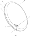
- Housing 10 of the units has a disc-like shape, that comprises generally two similar halves 11, 12, that are separated from each other and thus forming a small slit 13.
- the two halves 11, 12 of the housing 10 are made of material that doesn't allow for the passage of light, e.g. metal, plastic, wood etc., or material like glass or transparent plastic that allows for the passage of light, but is covered with coating that doesn't allow for the passage of light.
- a cylindrical wall 14 that allows for the passage of light, preferably made of a transparent or a perforated material, e.g. glass, plastic etc.
- the small slit 13 serves as a guide, that directs the light in parallel to the floor and prevents the light from shining directly or after reflecting from the floor into the user's eyes.
- the surface of the two halves 11, 12 of the housing 10, that is between the cylindrical wall 14 inside the slit 13 and the external edge 15 of the two halves 11, 12 is covered with a coating that absorbs the light preventing unintended reflections, e.g. black paint, powdered graphite etc.
- buttons 17 for operating the unit for example a power button, a light-intensity button, a volume button, a light intensity sensor button, a light-color button, buttons for configuring specific type of operation (e.g. setting the device as the emitter unit or the receiver unit) etc.
- buttons 17 might be also realized as sliders, touch-pads etc. or some or all of the interactive parts might be realized as a single touch-pad or touch-screen.
- means for sound detection Inside the housing 10 there are located means for sound detection, means for wireless communication, source(s) of light, optionally also any of the following: means for generating sound, means for generating vibrations, means for motion detection, means for heat detection, means for shaping beam of emitted light, means for providing power like a battery or a connection port and electrical means for configuring and managing the unit, for example a programmable logical system, e.g. a microcomputer, integrated circuit or PCB-based controller.
- a programmable logical system e.g. a microcomputer, integrated circuit or PCB-based controller.
- the housing 10 can be described with following dimensions:
- the emitter unit and the receiver unit has housing 10 that has outer diameter of 20 cm, height of 2,1 cm and its slit is 5 mm wide, with its upper and lower edge rounded.
- FIG. 3 , 4 and 5 there is presented another embodiment of the construction of the units of the baby monitor assembly.
- the housing 30 is again generally flat and disc-like shaped, however in this embodiment the emitted light doesn't pass via the small slit, but through either a partly or fully transparent part of the housing.
- the unit comprises a flat, generally circular bottom cover 31.
- the bottom cover 31 can be provided with an opening 32, that can serve e.g. as an opening for accessing internals of the unit (e.g. to manually change setting of the unit) or even just as an opening for changing the batteries.
- the opening 32 has two straight and two arched edges, but it should be understood that practically any shape of the opening is possible (circular, rectangular or polygonal), as long as it doesn't compromise the structural strength of the bottom cover 31.
- the bottom cover 31, from the side that is in contact with the floor, can be provided with gripping means, e.g. rubber protrusions, so that it doesn't slide easily on the floor.
- gripping means e.g. rubber protrusions
- an internal housing 33 which has generally the same outer dimension as the bottom cover 31.
- Internal housing 33 has a disc-like shape, with generally flat surface that comes in contact with the bottom cover 31 around the units' periphery and rises above the bottom cover 31.
- the upper external edge of the internal housing 33 can be rounded.
- the internal housing can have a lower cylindrical portion near its' center (central recess), so that it can provide a space suitable for inserting means for emitting light, e.g. a LED module 34 with several LED diodes.
- the unit In the ring-like part of the internal housing that is elevated above the bottom cover there is provided space for inserting internal components of the unit, such as power means (e.g. batteries), microphone, speaker, logic system etc.
- power means e.g. batteries
- microphone e.g. microphone
- speaker e.g. speaker
- logic system e.g. logic system
- the internal housing can be attached to the bottom cover by any known means, e.g. screws, clasps, glue.
- sealing means for protecting internal components from water, e.g. rubber seals, waterproof glue etc.
- the bottom cover and central recess of the internal housing should be also provided with sealing means.
- the LED module 34 that fits within the central recess is preferably securely attached to the internal housing 33, so that it doesn't move around while the device is moved or carried - it can be assured by any known means, e.g. screws or clasps.
- the LED module 34 is provided with several diodes and these diodes are preferably equally spaced from the center and from each other.
- the number of diodes in the module can vary, but a single diode might not emit enough light or emit the light ununiformly, so that preferably there are several diodes in the module, e.g. three, four, five, six, seven, eight, nine etc.
- an external housing 35 that has a dome-like shape with funnel-like recessed center. It is preferably made of partly or fully transparent material, e.g. transparent plastic.
- the upper part 36 of the external housing 35 (upper being the part that is above the internal housing 33 in the unit) and the funnel-like recess are preferably covered with a reflective coating, e.g. metalized. Such coating provides a mirror-effect for the light generated by the LED module 34 and thus guides the beams so that they leave the external housing 35 in parallel to the floor.
- a dark coating e.g. black mat or graphite etc.
- the shape of the funnel-like recess can be that of a focusing mirror, e.g. of an inclined arch revolved around the axis.
- a sensor 37 preferably a motion sensor, e.g. a microwave motion sensor, that triggers the unit upon detecting movement.
- a motion sensor e.g. a microwave motion sensor
- the upper cover 38 that limits the field of view of the sensor 37, so that the sensor 37 can detect movement around the unit but not above it.
- the upper cover 38 therefore needs to be impervious or reflective for the signals that the sensor operates with, e.g. made of metal such as steel.
- the upper covers' legs rest on the top surface of the external housing 35 and can be connected thereto by any known means of screws, clasps, glue, a tight fit with complementary holes in the external cover, etc.
- Parts of the unit of the baby monitor assemble such as bottom cover 31, internal housing 33, external housing 35 and base of the LED module 34 can be made of glass or plastic or, speaking about the parts that don't need to be transparent, also out of wood or metal. Parts can be made out of non-transparent materials or out of transparent materials covered with a type of coating, e.g. painted or metalized. In case the parts are made of plastic, they can be injection molded thus reducing costs of production.
- the second embodiment presents no slit around its' periphery similar to the small slit 13 from the first embodiment, it should be noted that while comparing Fig. 3 and Fig. 5 it is easily visible, that there is a space between the upper part of the internal housing 33 and upper part 36 of external housing, that creates a slit which in assembled state is covered by the transparent part of external housing 35. Thus, one could say that a slit doesn't need to be visible/accessible from the outside, as long as it is present within the unit so that it can take part in guiding the emitted light.
- the above-described unit can also be mounted to the bottom side of the baby's bed, hence can be equipped with conventional attaching means, such as grips, screws, bolts, adhesive tape etc.
- the housing can be flat so that in case of accidental stepping onto the unit the person won't get hurt by an edge or spike etc.
- the housing can be also dome-like shaped, or even can have a shape of a full or of a half of a polyhedron, preferably with rounded edges.
- the above described shapes of the units' housing are disc-like, cylindrical and close to being axisymmetric. It should be understood, that the shape of the housing, as seen from above, can differ from axisymmetric, e.g. can be a polygon like a hexagon, an octagon, a decagon etc., or even a triangle.
- the shape of the unit is that it has means, e.g. a small slit around its' periphery, so that it can emit light in parallel to the floor without shining it directly or by reflection from the floor into the users' eyes.
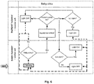
- FIG. 6 there is presented an exemplary block diagram of how the baby monitor assembly reacts when triggered by sounds emitted by the baby.
- the emitter unit which is located near the baby, is provided with means for sound detection, such as a microphone. While the emitter unit is turned on, the microphone is preferably always 'listening'. When the microphone detects the sound, the emitter's logic system examines it according to predetermined set of rules, e.g. checks its frequency and/or amplitude, to determine if the sound originated from the baby or from any other source. If the emitter's logic determines, that the sound originated from the baby, the emitter powers up and proceeds along the path 'Yes', otherwise, the emitter returns to 'listening' mode, also called 'stand-by' mode throughout this application.
- predetermined set of rules e.g. checks its frequency and/or amplitude
- the logic system can compare the detected sound with a database of known sounds, to determine the source of the sound. If the sound is found to originate e.g. from a bus passing by, the door being locked or a dog barking in the street etc., namely - not from within the baby's room and especially was not generated by the baby - the emitter unit doesn't power up any further and returns to listening mode.
- the logic system can comprise an algorithm that mathematically checks if the detected sound fulfills requirements of predetermined mathematical equations, that describe most or even all of the possible sounds that can be generated by the baby, which can comprise sounds like the baby's cry, coughing, baby-chatter, baby's movements in the bed, sounds of baby's arms/legs/head impacting sides of the baby's bed etc.
- the units of the baby monitor assembly can comprise means for distinguishing sources of the detected sound, this is only a preferable option.
- the units only check the volume of the detected sound, regardless of its' origin, and activate when the measured volume exceeds the predetermined value, which preferably can be adjusted to match different conditions of different flats and homes.
- the emitter determines, that the sound originates/could originate from the baby
- the emitter powers up and begins transmitting sounds to the receiver unit, located near the parent.
- the receiver unit powers up, plays the sound received from the emitter unit and waits for the parent's reaction. If the receiver unit detects, that the parent is not going to go and check on the baby (e.g. by detecting movement near the floor), the receiver unit does nothing more. If the receiver unit detects, that the parent is going to check on the baby, the receiver unit checks the light intensity within its vicinity. If it detects that it is dark, e.g. by using the light intensity sensor and comparing it with the predetermined value that is considered to be 'dark', the receiver unit starts emitting light, especially in parallel to the floor. This helps the parent to find the path across the floor and go around any obstacles present on the floor.
- Similar movement detection and powering up to emit light is carried out by the emitter unit.
- the emitter unit After transmitting sounds from the baby's room to the receiver unit, if the receiver unit started emitting light, the emitter unit also checks the intensity of light within its vicinity. If it detects, that it is not dark enough in the room (e.g. because the parents left the light on), it does not start emitting light, if it detects that it is dark - it starts emitting light. It can begin this action either after receiving information from the receiver unit, that the receiver unit started emitting light, or it can wait unit it detects movement in the baby's room (e.g. of the door opening or the parent walking into the room) and thus preserve energy.
- the process of triggering the baby monitor assembly can be regulated by a predetermined set of rules that organizes how long certain actions/processes can last. They can also determine the time intervals between the assembly can be triggered again etc. For example, if the emitter unit detects the first sound/noise in the baby's room, it powers up and awaits the next sound/noise for a predetermined time, e.g. 30 seconds, preferably 10 seconds or less. If the emitter unit detects the next sound/noise within this time frame and that sound/noise fulfills predetermined requirements, the baby monitor assembly becomes triggered, otherwise it goes back to stand-by mode.
- a predetermined set of rules that organizes how long certain actions/processes can last. They can also determine the time intervals between the assembly can be triggered again etc. For example, if the emitter unit detects the first sound/noise in the baby's room, it powers up and awaits the next sound/noise for a predetermined time, e.g. 30
- the sound transmission to the receiver unit without parent's reaction can last a predetermined amount of time, e.g. 5 minutes, preferably 2 minutes or less. If within that time the parent doesn't react, it is a signal for the baby monitor assembly that emitting light will not be necessary and after the said time is over the baby monitor assembly stops transmitting sounds and goes into 'listening' mode.
- powering down and going into stand-by mode can be initiated by the user (the parent), e.g. by pressing a button or even by a voice command.
- both the emitter unit and the receiver unit of the baby monitor assembly are provided with means for wireless communication, use cases in which the communication means do not have to be used are also foreseen.
- the emitter unit and the receiver unit can serve as stand-alone devices, that do not communicate directly with each other. Example of such mode of operation is described below.
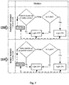
- Fig. 7 it presents a block diagram similar to the one shown in Fig. 6 , but simpler.
- the baby monitor assembly works in a way that uses less types of sensors per device (emitter unit, receiver unit) than the previously described embodiments and this mode of operation doesn't include interaction between the devices.
- the emitter unit and receiver unit are in normal operation in a stand-by mode, and can be triggered by detecting that the parent or the baby is approaching. It can be realized preferably by using motion sensors, heat sensors or optionally sound sensors that could detect the sounds generated by a walking person or a moving baby. If the device is triggered, it checks if it is dark in its vicinity, e.g. by using light intensity sensor and comparing measured value with the predetermined value. If the device determines, that it is 'dark', it starts emitting light, otherwise - it does nothing and goes back to stand-by mode.
- the process of triggering the baby monitor assembly can be regulated by the predetermined set of rules that organizes how long certain actions/processes can last. These rules can determine for how long the device will be emitting light after being triggered, e.g. for 60 seconds, preferably 30 seconds or less. It can also determine if and how often the device, after being triggered, will check if emitting light is needed. For example, in a scenario when the parent has to change the baby's diaper, the parent might turn on the main light in the room and so - the light from the baby monitor assembly won't be needed for the time being. Therefore, both the emitter and the receiver unit can be set to, after being triggered, emit light for e.g.
- Mentioned time intervals can be set according to the need, but set values should generally include energy efficiency (so that the devices won't emit light when it is not needed) and personal safety (so that the device won't stop emitting light while a person is still walking near it).
- the baby monitor assembly can go back to stand-by mode as a result of the parent's action, e.g. pressing a button, gesture, voice command etc.
- the device can be further provided with means for recognizing whether the detected movement is that of a baby/parent, or of an animal, so that if there is a cat, a dog, within the house or even just a bug flies near the device, it won't trigger.
- means for recognizing whether the detected movement is that of a baby/parent, or of an animal so that if there is a cat, a dog, within the house or even just a bug flies near the device, it won't trigger.
- Such distinction can be realized by combining and/or programming motion and/or heat sensors, that will distinguish between the situation when the device should be triggered and when it shouldn't.
- the two units might not emit enough light to illuminate all possible obstacles along the way.
- additional units might be added. These additional units might be configurable, to connect with the receiver unit, so that when the receiver unit would emit light, they would also activate to emit light. Such configuration could be chosen by the user, e.g. by pressing a button.
- the receiver unit might be provided with a microphone and the emitter unit might be provided with a speaker.
- the baby monitor assembly might use it's means for wireless communication to transmit voice of the parent to the baby to calm it down. This could be triggered by the parent's action, for example pressing a button, making a gesture, giving a voice command etc.
- Such embodiment could be especially helpful in cases when the baby is awakening and hearing the parent's voice will be enough for the baby to return to sleep, whereas going to the baby personally could lead to fully waking up the baby.
- the emitter unit and the receiver unit of the baby monitor assembly can be identical in their construction and/or in their functionality.
- the user would be able to configure which device would serve as the emitter unit and as the receiver unit.
- the emitter unit is of the type described in the present application (generally flat, disc-like shape, that can emit light etc.), while the receiver unit is the user's electronic device, e.g. smartphone, computer, tablet etc.
- the user's electronic device e.g. smartphone, computer, tablet etc.
- Such electronic devices provide even more possibilities to configure and personalize type of notifying the parent about detected noise and/or movement in the baby's room, e.g. by using complex sound alarms, vibrations etc.
- these complex electronic devices might emit too much light and therefore be less convenient for the use at night.
- the baby monitor assembly can establish another way of communication between the parent and the child, besides sounds.
- Both the emitter unit and the receiver units can be set to emit light upon being triggered without initializing transfer of sounds.
- One such configuration could be realized by detecting a predetermined action, e.g. sound or gesture, and upon detecting such action from the baby by the emitter unit, e.g. emitting light by the receiver unit near the parent. After that, if the receiver unit detects a predetermined action from the parent, e.g. a gesture, the emitter unit near the baby would notify the baby, e.g. by means of vibration or emitting light. This would mean for the baby, that the parent is nearby and alert, without further awakening the baby.
- a predetermined action e.g. sound or gesture
Landscapes
- Engineering & Computer Science (AREA)
- General Engineering & Computer Science (AREA)
- Physics & Mathematics (AREA)
- Child & Adolescent Psychology (AREA)
- General Physics & Mathematics (AREA)
- General Health & Medical Sciences (AREA)
- Health & Medical Sciences (AREA)
- Business, Economics & Management (AREA)
- Emergency Management (AREA)
- Spectroscopy & Molecular Physics (AREA)
- Computer Networks & Wireless Communication (AREA)
- Multimedia (AREA)
- Computer Security & Cryptography (AREA)
- Environmental & Geological Engineering (AREA)
- Alarm Systems (AREA)
- Accommodation For Nursing Or Treatment Tables (AREA)
- Emergency Alarm Devices (AREA)
Claims (15)
- Eine Babyphone-Einheit, die eine Sendereinheit und eine Empfängereinheit umfasst, wobei die Sendereinheit die Folgenden umfasst:- Mittel zur Tonerkennung, vorzugsweise ein Mikrofon,- Mittel zur Kommunikation mit der Empfängereinheit, vorzugsweise Mittel zur drahtlosen Kommunikation, insbesondere über WiFi, Bluetooth oder Radio,- ein im Allgemeinen flaches Gehäuse (10, 30) mit einem Schlitz (13) in der Nähe seiner Peripherie,- eine Lichtquelle, vorzugsweise LED-Dioden,wobei die Empfängereinheit die Folgenden umfasst:- Mittel zur Kommunikation mit der Sendereinheit, vorzugsweise Mittel zur drahtlosen Kommunikation, insbesondere über WiFi, Bluetooth oder Radio,- Mittel zur Signalisierung, vorzugsweise geeignet zum Aussenden von Licht-, Schall- oder Vibrationssignalenwobei die Sendereinheit so konfiguriert ist, dass sie Geräusche, die von dem Baby erzeugt werden, durch die Mittel zur Tonerkennung erkennt und bei Erkennung eines vorbestimmten Geräuschtyps Informationen über die Mittel zur Kommunikation mit der Empfängereinheit an die Empfängereinheit sendet,
wobei die Empfängereinheit zum Empfangen von Informationen von der Sendereinheit geeignet und konfiguriert ist; durch die genannten Mittel zur Kommunikation mit der Sendereinheit und zur Benachrichtigung des Elternteils durch die genannten Signalisierungsmittel, vorzugsweise unter Verwendung von Licht-, Schall- oder Vibrationssignalen, beim Empfang von Informationen von der Sendereinheit,
dadurch gekennzeichnet, dass die Sendereinheit geeignet und konfiguriert ist, um unter dem Kinderbettchen, Bettchen oder dergleichen eines Babys angeordnet zu werden, und dass der Schlitz (13) im Gehäuse (10, 30) der Sendereinheit den Durchgang von Licht von der im Gehäuse (10, 30) angeordneten Lichtquelle ermöglicht und konfiguriert ist, um den Lichtstrahl selektiv im Wesentlichen parallel zum Boden auszusenden, so dass der Lichtstrahl weder direkt scheint noch in die Augen des Babys und des Benutzers reflektiert wird. - Die Babyphone-Einheit nach Anspruch 1, dadurch gekennzeichnet, dass sie so konfiguriert ist, dass die Sendereinheit bei der ersten Erfassung einer vorbestimmten Art des Geräusches eingeschaltet wird und auf die zweite Erfassung der vorbestimmten Art des Geräusches innerhalb eines vorbestimmten Zeitintervalls von der ersten Erfassung an wartet, und nur bei einer solchen zweiten Erfassung innerhalb des vorbestimmten Zeitintervalls von der ersten Erfassung an - die Sendereinheit Informationen an die Empfängereinheit sendet, um die Eltern zu benachrichtigen, und mit der Erzeugung von Licht durch den Schlitz (13) beginnt.
- Die Babyphone-Einheit nach Anspruch 1 oder 2, dadurch gekennzeichnet, dass die Sendereinheit mit einem Lichtfilter versehen ist, um das Spektrum eines blauen Lichts aus dem von ihr emittierten Licht herauszufiltern, vorzugsweise um das Licht einer Wellenlänge zwischen 450 und 500 nm herauszufiltern.
- Die Babyphone-Einheit nach Anspruch 1, 2 oder 3, dadurch gekennzeichnet, dass die Sendereinheit ferner Befestigungsmittel zum Befestigen der Sendereinheit an der Unterseite des Bettes/Krippe umfasst.
- Die Babyphone-Einheit nach Anspruch 1, 2, 3 oder 4, dadurch gekennzeichnet, dass die Sendereinheit so konfiguriert ist, dass sie die Lichtintensität je nach den Präferenzen des Benutzers allmählich erhöht oder verringert.
- Die Babyphone-Einheit nach Anspruch 1, 2, 3, 4 oder 5, dadurch gekennzeichnet, dass im Inneren der Sendereinheit ein Satz von farbigen Lichtquellen, vorzugsweise LEDs verschiedener Farben, vorhanden ist, die so programmiert werden können, dass sie Licht einer bevorzugten Farbe und/oder mit einer bevorzugten Sequenz emittieren.
- Die Babyphone-Einheit nach einem der vorhergehenden Ansprüche von 1 bis 6, dadurch gekennzeichnet, dass die Empfängereinheit einen Lautsprecher aufweist und die Sendeeinheit zum Übertragen von durch das Mikrofon erfassten Schall an die Empfängereinheit konfiguriert ist, um von der Empfängereinheit an den Benutzer wiedergegeben zu werden, vorzugsweise über den Lautsprecher.
- Die Babyphone-Einheit nach einem der vorhergehenden Ansprüche von 1 bis 7, dadurch gekennzeichnet, dass die Empfängereinheit ferner mit einer Schallaufzeichnungseinrichtung, vorzugsweise einem Mikrofon, versehen ist und die Empfängereinheit geeignet und konfiguriert ist, von der Schallaufzeichnungseinrichtung der Empfängereinheit aufgezeichnete Schall an die Sendeeinheit zu übertragen, und die Sendeeinheit ferner mit einem Lautsprecher versehen ist und geeignet und konfiguriert ist, von der Empfängereinheit empfangene Schall zu emittieren.
- Die Babyphone-Einheit nach Anspruch 8, dadurch gekennzeichnet, dass die Empfängereinheit so konfiguriert ist, dass die Übertragung von Schall von der Empfängereinheit zur Sendeeinheit nur bei direkter Interaktion des Benutzers mit der Empfängereinheit, vorzugsweise unter Verwendung einer Taste, eines Schalters oder mit einem Sprachbefehl, erfolgt.
- Die Babyphone-Einheit nach einem der vorhergehenden Ansprüche von 1 bis 9, dadurch gekennzeichnet, dass die Sendereinheit ferner einen Bewegungssensor (37) und/oder einen Lichtintensitätssensor umfasst.
- Die Babyphone-Einheit nach einem der vorhergehenden Ansprüche von 1 bis 10, dadurch gekennzeichnet, dass die Sendereinheit und/oder die Empfängereinheit mit einer internen Stromquelle, vorzugsweise einer Batterie oder mit einem Anschluss an eine externe Stromquelle, oder noch bevorzugter mit sowohl der internen Stromquelle als auch dem Anschluss an die externe Stromquelle versehen sind.
- Die Babyphone-Einheit nach einem der vorhergehenden Ansprüche, dadurch gekennzeichnet, dass das Gehäuse (10, 30) der Sendereinheit und/oder der Empfängereinheit eine scheibenartige Form mit im Wesentlichen flachen Ober- und Unterseiten aufweist.
- Die Babyphone-Einheit nach einem der vorhergehenden Ansprüche, dadurch gekennzeichnet, dass eine einzelne Linse oder ein Satz von Linsen in dem Gehäuse (10, 30), vorzugsweise in der Nähe den Schlitz (13), zur Formung des Lichtstrahls angeordnet ist.
- Die Babyphone-Einheit nach einem der vorhergehenden Ansprüche, dadurch gekennzeichnet, dass die Sendereinheit und die Empfängereinheit identische Vorrichtungen sind.
- Die Babyphone-Einheit nach einem der vorhergehenden Ansprüche von 1 bis 13, dadurch gekennzeichnet, dass die Empfängereinheit ein Smartphone oder ein Tablet ist.
Priority Applications (9)
| Application Number | Priority Date | Filing Date | Title |
|---|---|---|---|
| PL18461521T PL3531388T3 (pl) | 2018-02-23 | 2018-02-23 | Zespół do monitorowania dziecka |
| EP18461521.9A EP3531388B1 (de) | 2018-02-23 | 2018-02-23 | Babyüberwachungsanordnung |
| DK18461521.9T DK3531388T3 (da) | 2018-02-23 | 2018-02-23 | Babyovervågningsenhed |
| ES18461521T ES2860528T3 (es) | 2018-02-23 | 2018-02-23 | Conjunto de monitor para bebés |
| US16/975,180 US11232691B2 (en) | 2018-02-23 | 2019-02-08 | Baby monitor assembly |
| CA3091293A CA3091293A1 (en) | 2018-02-23 | 2019-02-08 | Baby monitor assembly |
| PCT/EP2019/053198 WO2019162113A1 (en) | 2018-02-23 | 2019-02-08 | Baby monitor assembly |
| AU2019225882A AU2019225882B2 (en) | 2018-02-23 | 2019-02-08 | Baby monitor assembly |
| ZA2020/05191A ZA202005191B (en) | 2018-02-23 | 2020-08-20 | Baby monitor assembly |
Applications Claiming Priority (1)
| Application Number | Priority Date | Filing Date | Title |
|---|---|---|---|
| EP18461521.9A EP3531388B1 (de) | 2018-02-23 | 2018-02-23 | Babyüberwachungsanordnung |
Publications (2)
| Publication Number | Publication Date |
|---|---|
| EP3531388A1 EP3531388A1 (de) | 2019-08-28 |
| EP3531388B1 true EP3531388B1 (de) | 2020-12-02 |
Family
ID=61283151
Family Applications (1)
| Application Number | Title | Priority Date | Filing Date |
|---|---|---|---|
| EP18461521.9A Not-in-force EP3531388B1 (de) | 2018-02-23 | 2018-02-23 | Babyüberwachungsanordnung |
Country Status (9)
| Country | Link |
|---|---|
| US (1) | US11232691B2 (de) |
| EP (1) | EP3531388B1 (de) |
| AU (1) | AU2019225882B2 (de) |
| CA (1) | CA3091293A1 (de) |
| DK (1) | DK3531388T3 (de) |
| ES (1) | ES2860528T3 (de) |
| PL (1) | PL3531388T3 (de) |
| WO (1) | WO2019162113A1 (de) |
| ZA (1) | ZA202005191B (de) |
Families Citing this family (3)
| Publication number | Priority date | Publication date | Assignee | Title |
|---|---|---|---|---|
| EP4006861A1 (de) * | 2020-11-30 | 2022-06-01 | Koninklijke Philips N.V. | Überwachungssystem |
| US20230083251A1 (en) * | 2021-09-13 | 2023-03-16 | MAE Holdings LLC | System and method for a wearable monitoring device |
| US20230265980A1 (en) * | 2022-01-29 | 2023-08-24 | James Ogbonna Ugwuogo | Convenient Courtesy Lighting (A.K.A Courtesy) |
Family Cites Families (10)
| Publication number | Priority date | Publication date | Assignee | Title |
|---|---|---|---|---|
| US6476724B1 (en) * | 1999-08-25 | 2002-11-05 | Cynthia J. Slomowitz | Crib gate position indicator |
| US20040061607A1 (en) * | 2002-09-27 | 2004-04-01 | Steve Pargman | Signal device |
| US7204614B2 (en) | 2003-10-09 | 2007-04-17 | Beacons, Llc | Portable, automated illumination device |
| US20110144455A1 (en) * | 2007-08-31 | 2011-06-16 | Bam Labs, Inc. | Systems and methods for monitoring a subject at rest |
| CN201417493Y (zh) | 2009-04-10 | 2010-03-03 | 深圳市捷美安防技术有限公司 | 带有动静报警的数字无线可视婴儿监护器 |
| CN102568155A (zh) * | 2010-12-31 | 2012-07-11 | 富泰华工业(深圳)有限公司 | 婴儿睡醒报警装置 |
| US20150157224A1 (en) * | 2013-12-05 | 2015-06-11 | Samsung Electronics Co., Ltd. | System and Method for Remotely Identifying and Characterizing Life Physiological Signs |
| FR3023699B1 (fr) * | 2014-07-21 | 2016-09-02 | Withings | Procede et dispositif de surveillance d'un bebe et d'interaction |
| BR112017004020A2 (pt) * | 2014-09-04 | 2018-01-23 | Koninklijke Philips Nv | sistema e método de monitoramento de seres vivos, dispositivo de monitoramento para uso no sistema, método para iniciar remotamente um protocolo de teste em uma conexão de internet entre uma unidade de monitoramento para monitorar seres vivos e um dispositivo de usuário, e produto de programa de software |
| US9629475B2 (en) * | 2014-12-30 | 2017-04-25 | Google Inc. | Crib with embedded smart sensors |
-
2018
- 2018-02-23 EP EP18461521.9A patent/EP3531388B1/de not_active Not-in-force
- 2018-02-23 PL PL18461521T patent/PL3531388T3/pl unknown
- 2018-02-23 ES ES18461521T patent/ES2860528T3/es active Active
- 2018-02-23 DK DK18461521.9T patent/DK3531388T3/da active
-
2019
- 2019-02-08 US US16/975,180 patent/US11232691B2/en not_active Expired - Fee Related
- 2019-02-08 AU AU2019225882A patent/AU2019225882B2/en not_active Ceased
- 2019-02-08 CA CA3091293A patent/CA3091293A1/en not_active Abandoned
- 2019-02-08 WO PCT/EP2019/053198 patent/WO2019162113A1/en not_active Ceased
-
2020
- 2020-08-20 ZA ZA2020/05191A patent/ZA202005191B/en unknown
Non-Patent Citations (1)
| Title |
|---|
| None * |
Also Published As
| Publication number | Publication date |
|---|---|
| PL3531388T3 (pl) | 2021-06-14 |
| AU2019225882B2 (en) | 2021-10-21 |
| DK3531388T3 (da) | 2021-03-01 |
| AU2019225882A1 (en) | 2020-09-10 |
| CA3091293A1 (en) | 2019-08-29 |
| ZA202005191B (en) | 2022-08-31 |
| WO2019162113A1 (en) | 2019-08-29 |
| US20210118277A1 (en) | 2021-04-22 |
| EP3531388A1 (de) | 2019-08-28 |
| US11232691B2 (en) | 2022-01-25 |
| ES2860528T3 (es) | 2021-10-05 |
Similar Documents
| Publication | Publication Date | Title |
|---|---|---|
| US11232691B2 (en) | Baby monitor assembly | |
| CN108605394B (zh) | 用于控制建筑物中的装置的内置机电设备 | |
| US5600305A (en) | Portable patient monitoring system | |
| US20160073479A1 (en) | Modular illumination device and associated systems and methods | |
| US9533235B2 (en) | Acousto-optical baby toy with a remote control monitoring function | |
| US11236896B1 (en) | Closed-door night light | |
| TW201740056A (zh) | 模組化的智慧家居照顧的照明裝置 | |
| ES2976732T3 (es) | Un dispositivo de monitoreo para detectar una presencia en un espacio y un procedimiento asociado | |
| WO2018006837A1 (zh) | 一种坐姿及照度集成监测设备及照明设备 | |
| CA3130774C (en) | Internet of things lock module | |
| US8567993B2 (en) | Emergency illumination device and method of operating an emergency illumination device | |
| US5933091A (en) | Remotely-actuated infrared-sensitive switch | |
| KR101893877B1 (ko) | 스마트폰 연동형 무드등 | |
| CN206207070U (zh) | 红外遥控灯 | |
| GB2189634A (en) | Fire protection device | |
| KR20200017990A (ko) | 무드 조명램프 | |
| KR20190100812A (ko) | 동작인식센서를 갖는 침대용 조명등 | |
| CN214580807U (zh) | 一种可以识别婴儿哭声的语音控制小夜灯电路及其小夜灯 | |
| CN206712087U (zh) | 一种插座防误触装置 | |
| CN221332347U (zh) | 控制盒及智能监护装置 | |
| US11959621B2 (en) | Illumination system with a plurality of motion detectors | |
| CN216253472U (zh) | 一种可与86盒共用的烟雾报警器 | |
| CN222108319U (zh) | 一种报警器 | |
| CN216496624U (zh) | 一种感应式紧凑型智能杀菌uv小夜灯 | |
| JP3605275B2 (ja) | 点灯用送信機 |
Legal Events
| Date | Code | Title | Description |
|---|---|---|---|
| PUAI | Public reference made under article 153(3) epc to a published international application that has entered the european phase |
Free format text: ORIGINAL CODE: 0009012 |
|
| STAA | Information on the status of an ep patent application or granted ep patent |
Free format text: STATUS: THE APPLICATION HAS BEEN PUBLISHED |
|
| AK | Designated contracting states |
Kind code of ref document: A1 Designated state(s): AL AT BE BG CH CY CZ DE DK EE ES FI FR GB GR HR HU IE IS IT LI LT LU LV MC MK MT NL NO PL PT RO RS SE SI SK SM TR |
|
| AX | Request for extension of the european patent |
Extension state: BA ME |
|
| STAA | Information on the status of an ep patent application or granted ep patent |
Free format text: STATUS: REQUEST FOR EXAMINATION WAS MADE |
|
| 17P | Request for examination filed |
Effective date: 20200227 |
|
| RBV | Designated contracting states (corrected) |
Designated state(s): AL AT BE BG CH CY CZ DE DK EE ES FI FR GB GR HR HU IE IS IT LI LT LU LV MC MK MT NL NO PL PT RO RS SE SI SK SM TR |
|
| GRAP | Despatch of communication of intention to grant a patent |
Free format text: ORIGINAL CODE: EPIDOSNIGR1 |
|
| STAA | Information on the status of an ep patent application or granted ep patent |
Free format text: STATUS: GRANT OF PATENT IS INTENDED |
|
| INTG | Intention to grant announced |
Effective date: 20200707 |
|
| GRAS | Grant fee paid |
Free format text: ORIGINAL CODE: EPIDOSNIGR3 |
|
| GRAA | (expected) grant |
Free format text: ORIGINAL CODE: 0009210 |
|
| STAA | Information on the status of an ep patent application or granted ep patent |
Free format text: STATUS: THE PATENT HAS BEEN GRANTED |
|
| AK | Designated contracting states |
Kind code of ref document: B1 Designated state(s): AL AT BE BG CH CY CZ DE DK EE ES FI FR GB GR HR HU IE IS IT LI LT LU LV MC MK MT NL NO PL PT RO RS SE SI SK SM TR |
|
| REG | Reference to a national code |
Ref country code: GB Ref legal event code: FG4D |
|
| REG | Reference to a national code |
Ref country code: AT Ref legal event code: REF Ref document number: 1341776 Country of ref document: AT Kind code of ref document: T Effective date: 20201215 Ref country code: CH Ref legal event code: EP |
|
| REG | Reference to a national code |
Ref country code: DE Ref legal event code: R096 Ref document number: 602018010401 Country of ref document: DE |
|
| REG | Reference to a national code |
Ref country code: IE Ref legal event code: FG4D |
|
| REG | Reference to a national code |
Ref country code: DK Ref legal event code: T3 Effective date: 20210225 |
|
| REG | Reference to a national code |
Ref country code: SE Ref legal event code: TRGR |
|
| REG | Reference to a national code |
Ref country code: NL Ref legal event code: FP |
|
| PG25 | Lapsed in a contracting state [announced via postgrant information from national office to epo] |
Ref country code: RS Free format text: LAPSE BECAUSE OF FAILURE TO SUBMIT A TRANSLATION OF THE DESCRIPTION OR TO PAY THE FEE WITHIN THE PRESCRIBED TIME-LIMIT Effective date: 20201202 Ref country code: FI Free format text: LAPSE BECAUSE OF FAILURE TO SUBMIT A TRANSLATION OF THE DESCRIPTION OR TO PAY THE FEE WITHIN THE PRESCRIBED TIME-LIMIT Effective date: 20201202 Ref country code: GR Free format text: LAPSE BECAUSE OF FAILURE TO SUBMIT A TRANSLATION OF THE DESCRIPTION OR TO PAY THE FEE WITHIN THE PRESCRIBED TIME-LIMIT Effective date: 20210303 Ref country code: NO Free format text: LAPSE BECAUSE OF FAILURE TO SUBMIT A TRANSLATION OF THE DESCRIPTION OR TO PAY THE FEE WITHIN THE PRESCRIBED TIME-LIMIT Effective date: 20210302 |
|
| PGFP | Annual fee paid to national office [announced via postgrant information from national office to epo] |
Ref country code: CH Payment date: 20210224 Year of fee payment: 4 Ref country code: IE Payment date: 20210223 Year of fee payment: 4 Ref country code: FR Payment date: 20210219 Year of fee payment: 4 Ref country code: IT Payment date: 20210228 Year of fee payment: 4 Ref country code: NL Payment date: 20210222 Year of fee payment: 4 |
|
| REG | Reference to a national code |
Ref country code: AT Ref legal event code: MK05 Ref document number: 1341776 Country of ref document: AT Kind code of ref document: T Effective date: 20201202 |
|
| PG25 | Lapsed in a contracting state [announced via postgrant information from national office to epo] |
Ref country code: LV Free format text: LAPSE BECAUSE OF FAILURE TO SUBMIT A TRANSLATION OF THE DESCRIPTION OR TO PAY THE FEE WITHIN THE PRESCRIBED TIME-LIMIT Effective date: 20201202 Ref country code: BG Free format text: LAPSE BECAUSE OF FAILURE TO SUBMIT A TRANSLATION OF THE DESCRIPTION OR TO PAY THE FEE WITHIN THE PRESCRIBED TIME-LIMIT Effective date: 20210302 |
|
| PGFP | Annual fee paid to national office [announced via postgrant information from national office to epo] |
Ref country code: ES Payment date: 20210303 Year of fee payment: 4 Ref country code: DK Payment date: 20210223 Year of fee payment: 4 Ref country code: DE Payment date: 20210222 Year of fee payment: 4 Ref country code: SE Payment date: 20210223 Year of fee payment: 4 Ref country code: BE Payment date: 20210222 Year of fee payment: 4 |
|
| PG25 | Lapsed in a contracting state [announced via postgrant information from national office to epo] |
Ref country code: HR Free format text: LAPSE BECAUSE OF FAILURE TO SUBMIT A TRANSLATION OF THE DESCRIPTION OR TO PAY THE FEE WITHIN THE PRESCRIBED TIME-LIMIT Effective date: 20201202 |
|
| REG | Reference to a national code |
Ref country code: LT Ref legal event code: MG9D |
|
| PG25 | Lapsed in a contracting state [announced via postgrant information from national office to epo] |
Ref country code: SK Free format text: LAPSE BECAUSE OF FAILURE TO SUBMIT A TRANSLATION OF THE DESCRIPTION OR TO PAY THE FEE WITHIN THE PRESCRIBED TIME-LIMIT Effective date: 20201202 Ref country code: SM Free format text: LAPSE BECAUSE OF FAILURE TO SUBMIT A TRANSLATION OF THE DESCRIPTION OR TO PAY THE FEE WITHIN THE PRESCRIBED TIME-LIMIT Effective date: 20201202 Ref country code: CZ Free format text: LAPSE BECAUSE OF FAILURE TO SUBMIT A TRANSLATION OF THE DESCRIPTION OR TO PAY THE FEE WITHIN THE PRESCRIBED TIME-LIMIT Effective date: 20201202 Ref country code: EE Free format text: LAPSE BECAUSE OF FAILURE TO SUBMIT A TRANSLATION OF THE DESCRIPTION OR TO PAY THE FEE WITHIN THE PRESCRIBED TIME-LIMIT Effective date: 20201202 Ref country code: PT Free format text: LAPSE BECAUSE OF FAILURE TO SUBMIT A TRANSLATION OF THE DESCRIPTION OR TO PAY THE FEE WITHIN THE PRESCRIBED TIME-LIMIT Effective date: 20210405 Ref country code: RO Free format text: LAPSE BECAUSE OF FAILURE TO SUBMIT A TRANSLATION OF THE DESCRIPTION OR TO PAY THE FEE WITHIN THE PRESCRIBED TIME-LIMIT Effective date: 20201202 Ref country code: LT Free format text: LAPSE BECAUSE OF FAILURE TO SUBMIT A TRANSLATION OF THE DESCRIPTION OR TO PAY THE FEE WITHIN THE PRESCRIBED TIME-LIMIT Effective date: 20201202 |
|
| PG25 | Lapsed in a contracting state [announced via postgrant information from national office to epo] |
Ref country code: AT Free format text: LAPSE BECAUSE OF FAILURE TO SUBMIT A TRANSLATION OF THE DESCRIPTION OR TO PAY THE FEE WITHIN THE PRESCRIBED TIME-LIMIT Effective date: 20201202 |
|
| PGFP | Annual fee paid to national office [announced via postgrant information from national office to epo] |
Ref country code: PL Payment date: 20210219 Year of fee payment: 4 |
|
| REG | Reference to a national code |
Ref country code: DE Ref legal event code: R097 Ref document number: 602018010401 Country of ref document: DE |
|
| PG25 | Lapsed in a contracting state [announced via postgrant information from national office to epo] |
Ref country code: IS Free format text: LAPSE BECAUSE OF FAILURE TO SUBMIT A TRANSLATION OF THE DESCRIPTION OR TO PAY THE FEE WITHIN THE PRESCRIBED TIME-LIMIT Effective date: 20210402 Ref country code: MC Free format text: LAPSE BECAUSE OF FAILURE TO SUBMIT A TRANSLATION OF THE DESCRIPTION OR TO PAY THE FEE WITHIN THE PRESCRIBED TIME-LIMIT Effective date: 20201202 |
|
| PLBE | No opposition filed within time limit |
Free format text: ORIGINAL CODE: 0009261 |
|
| STAA | Information on the status of an ep patent application or granted ep patent |
Free format text: STATUS: NO OPPOSITION FILED WITHIN TIME LIMIT |
|
| PG25 | Lapsed in a contracting state [announced via postgrant information from national office to epo] |
Ref country code: AL Free format text: LAPSE BECAUSE OF FAILURE TO SUBMIT A TRANSLATION OF THE DESCRIPTION OR TO PAY THE FEE WITHIN THE PRESCRIBED TIME-LIMIT Effective date: 20201202 Ref country code: LU Free format text: LAPSE BECAUSE OF NON-PAYMENT OF DUE FEES Effective date: 20210223 |
|
| 26N | No opposition filed |
Effective date: 20210903 |
|
| PG25 | Lapsed in a contracting state [announced via postgrant information from national office to epo] |
Ref country code: SI Free format text: LAPSE BECAUSE OF FAILURE TO SUBMIT A TRANSLATION OF THE DESCRIPTION OR TO PAY THE FEE WITHIN THE PRESCRIBED TIME-LIMIT Effective date: 20201202 |
|
| PG25 | Lapsed in a contracting state [announced via postgrant information from national office to epo] |
Ref country code: IS Free format text: LAPSE BECAUSE OF FAILURE TO SUBMIT A TRANSLATION OF THE DESCRIPTION OR TO PAY THE FEE WITHIN THE PRESCRIBED TIME-LIMIT Effective date: 20210402 |
|
| REG | Reference to a national code |
Ref country code: DE Ref legal event code: R119 Ref document number: 602018010401 Country of ref document: DE |
|
| REG | Reference to a national code |
Ref country code: DK Ref legal event code: EBP Effective date: 20220228 |
|
| REG | Reference to a national code |
Ref country code: SE Ref legal event code: EUG |
|
| REG | Reference to a national code |
Ref country code: NL Ref legal event code: MM Effective date: 20220301 |
|
| REG | Reference to a national code |
Ref country code: CH Ref legal event code: PL |
|
| REG | Reference to a national code |
Ref country code: BE Ref legal event code: MM Effective date: 20220228 |
|
| GBPC | Gb: european patent ceased through non-payment of renewal fee |
Effective date: 20220223 |
|
| PG25 | Lapsed in a contracting state [announced via postgrant information from national office to epo] |
Ref country code: SE Free format text: LAPSE BECAUSE OF NON-PAYMENT OF DUE FEES Effective date: 20220224 |
|
| PG25 | Lapsed in a contracting state [announced via postgrant information from national office to epo] |
Ref country code: NL Free format text: LAPSE BECAUSE OF NON-PAYMENT OF DUE FEES Effective date: 20220301 Ref country code: FR Free format text: LAPSE BECAUSE OF NON-PAYMENT OF DUE FEES Effective date: 20220228 |
|
| PG25 | Lapsed in a contracting state [announced via postgrant information from national office to epo] |
Ref country code: LI Free format text: LAPSE BECAUSE OF NON-PAYMENT OF DUE FEES Effective date: 20220228 Ref country code: IE Free format text: LAPSE BECAUSE OF NON-PAYMENT OF DUE FEES Effective date: 20220223 Ref country code: GB Free format text: LAPSE BECAUSE OF NON-PAYMENT OF DUE FEES Effective date: 20220223 Ref country code: DK Free format text: LAPSE BECAUSE OF NON-PAYMENT OF DUE FEES Effective date: 20220228 Ref country code: DE Free format text: LAPSE BECAUSE OF NON-PAYMENT OF DUE FEES Effective date: 20220901 Ref country code: CH Free format text: LAPSE BECAUSE OF NON-PAYMENT OF DUE FEES Effective date: 20220228 |
|
| PG25 | Lapsed in a contracting state [announced via postgrant information from national office to epo] |
Ref country code: BE Free format text: LAPSE BECAUSE OF NON-PAYMENT OF DUE FEES Effective date: 20220228 |
|
| REG | Reference to a national code |
Ref country code: ES Ref legal event code: FD2A Effective date: 20230329 |
|
| PG25 | Lapsed in a contracting state [announced via postgrant information from national office to epo] |
Ref country code: ES Free format text: LAPSE BECAUSE OF NON-PAYMENT OF DUE FEES Effective date: 20220224 |
|
| PG25 | Lapsed in a contracting state [announced via postgrant information from national office to epo] |
Ref country code: IT Free format text: LAPSE BECAUSE OF NON-PAYMENT OF DUE FEES Effective date: 20220223 |
|
| PG25 | Lapsed in a contracting state [announced via postgrant information from national office to epo] |
Ref country code: CY Free format text: LAPSE BECAUSE OF FAILURE TO SUBMIT A TRANSLATION OF THE DESCRIPTION OR TO PAY THE FEE WITHIN THE PRESCRIBED TIME-LIMIT Effective date: 20201202 |
|
| PG25 | Lapsed in a contracting state [announced via postgrant information from national office to epo] |
Ref country code: HU Free format text: LAPSE BECAUSE OF FAILURE TO SUBMIT A TRANSLATION OF THE DESCRIPTION OR TO PAY THE FEE WITHIN THE PRESCRIBED TIME-LIMIT; INVALID AB INITIO Effective date: 20180223 |
|
| PG25 | Lapsed in a contracting state [announced via postgrant information from national office to epo] |
Ref country code: MK Free format text: LAPSE BECAUSE OF FAILURE TO SUBMIT A TRANSLATION OF THE DESCRIPTION OR TO PAY THE FEE WITHIN THE PRESCRIBED TIME-LIMIT Effective date: 20201202 |
|
| PG25 | Lapsed in a contracting state [announced via postgrant information from national office to epo] |
Ref country code: PL Free format text: LAPSE BECAUSE OF NON-PAYMENT OF DUE FEES Effective date: 20220223 |
|
| PG25 | Lapsed in a contracting state [announced via postgrant information from national office to epo] |
Ref country code: TR Free format text: LAPSE BECAUSE OF FAILURE TO SUBMIT A TRANSLATION OF THE DESCRIPTION OR TO PAY THE FEE WITHIN THE PRESCRIBED TIME-LIMIT Effective date: 20201202 |
|
| PG25 | Lapsed in a contracting state [announced via postgrant information from national office to epo] |
Ref country code: MT Free format text: LAPSE BECAUSE OF FAILURE TO SUBMIT A TRANSLATION OF THE DESCRIPTION OR TO PAY THE FEE WITHIN THE PRESCRIBED TIME-LIMIT Effective date: 20201202 |