EP3531010A1 - Leuchtvorrichtung für kraftfahrzeug und beleuchtungs- und/oder signalisierungseinheit, die mit einer solchen vorrichtung ausgestattet ist - Google Patents
Leuchtvorrichtung für kraftfahrzeug und beleuchtungs- und/oder signalisierungseinheit, die mit einer solchen vorrichtung ausgestattet ist Download PDFInfo
- Publication number
- EP3531010A1 EP3531010A1 EP19158960.5A EP19158960A EP3531010A1 EP 3531010 A1 EP3531010 A1 EP 3531010A1 EP 19158960 A EP19158960 A EP 19158960A EP 3531010 A1 EP3531010 A1 EP 3531010A1
- Authority
- EP
- European Patent Office
- Prior art keywords
- unitary
- light
- additional
- upper portion
- beams
- Prior art date
- Legal status (The legal status is an assumption and is not a legal conclusion. Google has not performed a legal analysis and makes no representation as to the accuracy of the status listed.)
- Granted
Links
Images



Classifications
-
- F—MECHANICAL ENGINEERING; LIGHTING; HEATING; WEAPONS; BLASTING
- F21—LIGHTING
- F21S—NON-PORTABLE LIGHTING DEVICES; SYSTEMS THEREOF; VEHICLE LIGHTING DEVICES SPECIALLY ADAPTED FOR VEHICLE EXTERIORS
- F21S41/00—Illuminating devices specially adapted for vehicle exteriors, e.g. headlamps
- F21S41/20—Illuminating devices specially adapted for vehicle exteriors, e.g. headlamps characterised by refractors, transparent cover plates, light guides or filters
- F21S41/285—Refractors, transparent cover plates, light guides or filters not provided in groups F21S41/24 - F21S41/2805
-
- F—MECHANICAL ENGINEERING; LIGHTING; HEATING; WEAPONS; BLASTING
- F21—LIGHTING
- F21S—NON-PORTABLE LIGHTING DEVICES; SYSTEMS THEREOF; VEHICLE LIGHTING DEVICES SPECIALLY ADAPTED FOR VEHICLE EXTERIORS
- F21S41/00—Illuminating devices specially adapted for vehicle exteriors, e.g. headlamps
- F21S41/10—Illuminating devices specially adapted for vehicle exteriors, e.g. headlamps characterised by the light source
- F21S41/14—Illuminating devices specially adapted for vehicle exteriors, e.g. headlamps characterised by the light source characterised by the type of light source
- F21S41/141—Light emitting diodes [LED]
-
- F—MECHANICAL ENGINEERING; LIGHTING; HEATING; WEAPONS; BLASTING
- F21—LIGHTING
- F21S—NON-PORTABLE LIGHTING DEVICES; SYSTEMS THEREOF; VEHICLE LIGHTING DEVICES SPECIALLY ADAPTED FOR VEHICLE EXTERIORS
- F21S41/00—Illuminating devices specially adapted for vehicle exteriors, e.g. headlamps
- F21S41/10—Illuminating devices specially adapted for vehicle exteriors, e.g. headlamps characterised by the light source
- F21S41/14—Illuminating devices specially adapted for vehicle exteriors, e.g. headlamps characterised by the light source characterised by the type of light source
- F21S41/141—Light emitting diodes [LED]
- F21S41/143—Light emitting diodes [LED] the main emission direction of the LED being parallel to the optical axis of the illuminating device
-
- F—MECHANICAL ENGINEERING; LIGHTING; HEATING; WEAPONS; BLASTING
- F21—LIGHTING
- F21S—NON-PORTABLE LIGHTING DEVICES; SYSTEMS THEREOF; VEHICLE LIGHTING DEVICES SPECIALLY ADAPTED FOR VEHICLE EXTERIORS
- F21S41/00—Illuminating devices specially adapted for vehicle exteriors, e.g. headlamps
- F21S41/10—Illuminating devices specially adapted for vehicle exteriors, e.g. headlamps characterised by the light source
- F21S41/14—Illuminating devices specially adapted for vehicle exteriors, e.g. headlamps characterised by the light source characterised by the type of light source
- F21S41/141—Light emitting diodes [LED]
- F21S41/151—Light emitting diodes [LED] arranged in one or more lines
- F21S41/153—Light emitting diodes [LED] arranged in one or more lines arranged in a matrix
-
- F—MECHANICAL ENGINEERING; LIGHTING; HEATING; WEAPONS; BLASTING
- F21—LIGHTING
- F21S—NON-PORTABLE LIGHTING DEVICES; SYSTEMS THEREOF; VEHICLE LIGHTING DEVICES SPECIALLY ADAPTED FOR VEHICLE EXTERIORS
- F21S41/00—Illuminating devices specially adapted for vehicle exteriors, e.g. headlamps
- F21S41/20—Illuminating devices specially adapted for vehicle exteriors, e.g. headlamps characterised by refractors, transparent cover plates, light guides or filters
- F21S41/24—Light guides
-
- F—MECHANICAL ENGINEERING; LIGHTING; HEATING; WEAPONS; BLASTING
- F21—LIGHTING
- F21S—NON-PORTABLE LIGHTING DEVICES; SYSTEMS THEREOF; VEHICLE LIGHTING DEVICES SPECIALLY ADAPTED FOR VEHICLE EXTERIORS
- F21S41/00—Illuminating devices specially adapted for vehicle exteriors, e.g. headlamps
- F21S41/20—Illuminating devices specially adapted for vehicle exteriors, e.g. headlamps characterised by refractors, transparent cover plates, light guides or filters
- F21S41/25—Projection lenses
-
- F—MECHANICAL ENGINEERING; LIGHTING; HEATING; WEAPONS; BLASTING
- F21—LIGHTING
- F21S—NON-PORTABLE LIGHTING DEVICES; SYSTEMS THEREOF; VEHICLE LIGHTING DEVICES SPECIALLY ADAPTED FOR VEHICLE EXTERIORS
- F21S41/00—Illuminating devices specially adapted for vehicle exteriors, e.g. headlamps
- F21S41/20—Illuminating devices specially adapted for vehicle exteriors, e.g. headlamps characterised by refractors, transparent cover plates, light guides or filters
- F21S41/25—Projection lenses
- F21S41/265—Composite lenses; Lenses with a patch-like shape
-
- F—MECHANICAL ENGINEERING; LIGHTING; HEATING; WEAPONS; BLASTING
- F21—LIGHTING
- F21S—NON-PORTABLE LIGHTING DEVICES; SYSTEMS THEREOF; VEHICLE LIGHTING DEVICES SPECIALLY ADAPTED FOR VEHICLE EXTERIORS
- F21S41/00—Illuminating devices specially adapted for vehicle exteriors, e.g. headlamps
- F21S41/60—Illuminating devices specially adapted for vehicle exteriors, e.g. headlamps characterised by a variable light distribution
- F21S41/65—Illuminating devices specially adapted for vehicle exteriors, e.g. headlamps characterised by a variable light distribution by acting on light sources
- F21S41/663—Illuminating devices specially adapted for vehicle exteriors, e.g. headlamps characterised by a variable light distribution by acting on light sources by switching light sources
-
- F—MECHANICAL ENGINEERING; LIGHTING; HEATING; WEAPONS; BLASTING
- F21—LIGHTING
- F21W—INDEXING SCHEME ASSOCIATED WITH SUBCLASSES F21K, F21L, F21S and F21V, RELATING TO USES OR APPLICATIONS OF LIGHTING DEVICES OR SYSTEMS
- F21W2102/00—Exterior vehicle lighting devices for illuminating purposes
- F21W2102/10—Arrangement or contour of the emitted light
- F21W2102/13—Arrangement or contour of the emitted light for high-beam region or low-beam region
- F21W2102/135—Arrangement or contour of the emitted light for high-beam region or low-beam region the light having cut-off lines, i.e. clear borderlines between emitted regions and dark regions
-
- F—MECHANICAL ENGINEERING; LIGHTING; HEATING; WEAPONS; BLASTING
- F21—LIGHTING
- F21W—INDEXING SCHEME ASSOCIATED WITH SUBCLASSES F21K, F21L, F21S and F21V, RELATING TO USES OR APPLICATIONS OF LIGHTING DEVICES OR SYSTEMS
- F21W2102/00—Exterior vehicle lighting devices for illuminating purposes
- F21W2102/10—Arrangement or contour of the emitted light
- F21W2102/13—Arrangement or contour of the emitted light for high-beam region or low-beam region
- F21W2102/135—Arrangement or contour of the emitted light for high-beam region or low-beam region the light having cut-off lines, i.e. clear borderlines between emitted regions and dark regions
- F21W2102/14—Arrangement or contour of the emitted light for high-beam region or low-beam region the light having cut-off lines, i.e. clear borderlines between emitted regions and dark regions having vertical cut-off lines; specially adapted for adaptive high beams, i.e. wherein the beam is broader but avoids glaring other road users
-
- F—MECHANICAL ENGINEERING; LIGHTING; HEATING; WEAPONS; BLASTING
- F21—LIGHTING
- F21W—INDEXING SCHEME ASSOCIATED WITH SUBCLASSES F21K, F21L, F21S and F21V, RELATING TO USES OR APPLICATIONS OF LIGHTING DEVICES OR SYSTEMS
- F21W2102/00—Exterior vehicle lighting devices for illuminating purposes
- F21W2102/10—Arrangement or contour of the emitted light
- F21W2102/13—Arrangement or contour of the emitted light for high-beam region or low-beam region
- F21W2102/135—Arrangement or contour of the emitted light for high-beam region or low-beam region the light having cut-off lines, i.e. clear borderlines between emitted regions and dark regions
- F21W2102/155—Arrangement or contour of the emitted light for high-beam region or low-beam region the light having cut-off lines, i.e. clear borderlines between emitted regions and dark regions having inclined and horizontal cutoff lines
-
- F—MECHANICAL ENGINEERING; LIGHTING; HEATING; WEAPONS; BLASTING
- F21—LIGHTING
- F21W—INDEXING SCHEME ASSOCIATED WITH SUBCLASSES F21K, F21L, F21S and F21V, RELATING TO USES OR APPLICATIONS OF LIGHTING DEVICES OR SYSTEMS
- F21W2107/00—Use or application of lighting devices on or in particular types of vehicles
- F21W2107/10—Use or application of lighting devices on or in particular types of vehicles for land vehicles
-
- F—MECHANICAL ENGINEERING; LIGHTING; HEATING; WEAPONS; BLASTING
- F21—LIGHTING
- F21Y—INDEXING SCHEME ASSOCIATED WITH SUBCLASSES F21K, F21L, F21S and F21V, RELATING TO THE FORM OR THE KIND OF THE LIGHT SOURCES OR OF THE COLOUR OF THE LIGHT EMITTED
- F21Y2115/00—Light-generating elements of semiconductor light sources
- F21Y2115/10—Light-emitting diodes [LED]
Definitions
- the present invention relates in particular to a light device for a motor vehicle, and to a lighting and / or signaling unit provided with such a device.
- a preferred application relates to the automotive industry, for the equipment of vehicles, in particular for the production of devices capable of emitting light beams, also called lighting and / or signaling functions, generally meeting regulations.
- the invention can allow the production of a light beam at the front of the vehicle.
- a light beam emitted by front headlights has a first lighting zone 4 extending to the ground of the track 2 on which the vehicle 1 is traveling, and a second lighting zone 5 extending to the ground of the track 3 .
- the second lighting zone 5 has a cutoff 6 so that the area of the second lighting zone 5 is smaller than the area of the first zone
- the cut-off 6 makes it possible not to dazzle a driver of a vehicle traveling on track 3.
- a light beam emitting device having a plurality of light emitting diodes arranged in the form of a matrix with lines and columns of diodes, each diode being associated with a complex optical element for projecting a unitary part of the global beam.
- the individual and selective control of the diodes makes it possible to shape a resulting beam with great freedom of shape definition.
- the present invention aims to remedy at least in part the disadvantages of current techniques.
- the sloping form gives the resulting projection an inclined cutoff which corresponds to a more progressive shape than that produced by the current pixel arrays for which the cuts are vertical.
- the remainder of the upper portion of the resulting beam extends laterally from the slope in a homogeneous manner by virtue of the rectangular shape, which may be square, of at least a second beam from the first beam.
- the device still benefits from the discretization enabled by the LED arrays, to adapt the projection to the desired lighting and / or signaling functions.
- the present invention also relates to a lighting and / or signaling unit of a motor vehicle equipped with at least one light device.
- This unit may comprise at least one additional device configured to produce a passing beam base beam.
- the additional device may allow to illuminate homogeneously substantially below the horizon line.
- the device of the invention can in turn allow at least to define the cutoff zone of a dipped beam.
- Another aspect of the invention is a method of controlling a light device.
- the present invention also relates to a vehicle equipped with at least one device and / or unit according to the present invention.
- the device is such that the upper portion of the unitary first beam shape is a trapezoid defined by the first lateral edge, a second lateral edge opposite the first lateral edge and comprising a slope, a first base located at the top and a second base, of greater width than the first base and opposite the first base.
- This provides a shape with two slopes ensuring the possibility of a beam cut right or left.
- the first unitary beam shape comprises a rectangular lower portion in the continuity of the second base.
- the first unitary beam downwards, for example just below the horizon line, preferably so as to operate a smooth connection with another beam, for example a base portion of a dipped beam. projected in a majority or all of the way below the horizon.
- the trapezoid is isosceles.
- the width of the first base is equal to that of the upper portion of the second unitary beam.
- the second unitary beam is part of the strict continuity of the first base, between the two slopes; the overlap zone of the two unit beams is then very weak and does not affect the slopes.
- the height of the upper portion of the first beam is equal to the height of the upper portion of the second unitary beam.
- the shape adaptation between the two unitary beams is increased accordingly.
- the largest width of the upper portion of the first unitary beam is twice as large as the largest width of the shape of the second unitary beam.
- the pitch of the pixels corresponding to the row of second unitary beams is thus half, offering a greater resolution of this part of the definition of the resulting road beam.
- the number of light sources assigned to the second unit beams is therefore greater than that of the light sources assigned to the first unit beams, and preferably of the order of two times greater.
- each first illumination unit preferably comprises for each first illumination unit a first light source belonging to the plurality of light sources, and a first optical element associated with said first light source and configured to receive light from said first associated light source. and to transmit one of the first unitary beams.
- each second illumination unit comprises a second light source belonging to the plurality of light sources, and a second optical element, associated with said second light source and configured to receive light from said associated second light source and to transmit a light source.
- second unitary beams are also included in each second illumination unit.
- the first light module is configured to produce, for each first unitary beam, a first additional unit beam.
- the first additional unitary beams are each located in the continuity and above a first unitary beam.
- the first light module comprises at least one additional row of additional first light sources belonging to the plurality of light sources, and at least one additional row of additional first optical elements each associated with one, different , first additional light sources, each first additional light source and the first additional additional optical element being configured to produce a first additional unit beam.
- the combination of the additional row of additional first light sources and the additional row of additional first optical elements is configured to produce an output beam projection predominantly or even entirely above the horizon line, to achieve or participate in realizing part of a driving beam.
- the second light module comprises at least one additional row of additional second light sources belonging to the plurality of light sources, and at least one additional row of additional second optical elements each associated with a different one of the second additional light sources.
- each second additional light source and the second associated additional optical element being configured to produce a second additional unit beam.
- the combination of the additional row of additional second light sources and the additional row of additional second optical elements is configured to produce an output beam projection, mostly all over the horizon line, to achieve or participate in realizing part of a driving beam.
- the second additional unitary beams are each located in the continuity and above a second unitary beam.
- a third light module comprises a row of third light sources belonging to the plurality of light sources, and third optical elements, individually associated with one different from the third light sources and configured to receive light from said third source. associated and to each transmit a unitary beam sloping formed by a third unitary beam, according to a third unitary beam shape determined by a shape of third optical elements, the unitary third beam form having an upper portion having a first side edge including a slope extending to a vertex of the third unitary beam shape such that a width dimension of the portion upper tends to decrease towards the summit; and wherein each of the third unit beams is associated with one of the second unit beams such that an upper corner of the upper portion of the second unit beam of said one of the second optical elements coincides with the vertex of the third unit beam of the second unit beam.
- third associated optical element and so that the upper portion extends laterally opposite the slope of the third unit beam of the third associated optical element; and wherein the first unitary beam and the third unitary beam associated with the same second unitary beam are
- the third module there is an additional element for generating unit beams on a slope.
- the provision of these additional slopes increases the definition resolution of the resulting beam envelope border; when it comes to the cut of a dipped beam, there is then a greater number of potential cutoff edges according to the width of the total beam possible.
- the shape of the first unitary beam and the shape of the third unitary beam are identical.
- the light modules each comprise an optical field element.
- an optical projection element is common to the light modules.
- control means comprise a dipped beam control configuration in which the control means is configured to turn on only one light source assigned to a unitary beam with a slope and to light a series of at least a light source assigned to a second unitary beam so as to form a resultant beam portion in the lateral continuity of said unitary slope beam.
- the row of first sources and possibly the row of third sources serves only to generate a single unitary beam at a time, whereas the row of second sources serves to generate the remainder of the beam width to be formed ( in particular the low beam beam area including the cutoff).
- the passing beam portion generated by the unitary slope beam and the second unit beams may form the low beam portion located around the horizon line (the high portion of the dipped beam); the remainder of the passing beam may be formed by a complementary beam, such as a "flat" beam, that is to say straight and homogeneous, essentially below the horizon line.
- one of the light modules and particularly advantageously the second light module, comprises a row of marking light sources each source of which is associated with an optical marking element.
- This assembly enables the generation of a plurality of unit marking beams that can be used to have a discrete projection element below the horizon line, either as a base portion of a dipped beam or as a base portion of a dipped beam. as over-illumination of the base portion of a dipped beam generated elsewhere.
- a "marking line" function to over-illuminate an area at the front of the vehicle can be achieved by this means.
- lighting can be controlled only from a series of at least one marker light source to produce a highlighted band in the lower portion of the dipped beam.
- the sources of the plurality of sources each comprise at least one light emitting diode.
- At least one of the row of first optical elements, the row of second optical elements, the row of third optical elements and possible rows of additional optical elements are made from a single piece of a material, in particular an optical material such as PMMA (polymethylmethacrylate), the optical elements of a row considered being juxtaposed edge to edge in the width direction of the beam to be produced.
- a material in particular an optical material such as PMMA (polymethylmethacrylate)
- the invention also relates to a lighting and / or signaling unit of a motor vehicle equipped with at least one device as described above.
- the terms relating to verticality, horizontality and transversality, or their equivalents refer to the position in which the lighting module is intended to be mounted in a vehicle.
- the terms “vertical” and “horizontal” are used in the present description to designate directions, in an orientation perpendicular to the horizon plane for the term “vertical”, and in an orientation parallel to the horizon plane for the term “horizontal”. They are to be considered in the operating conditions of the device in a vehicle.
- the term “width” refers to a dimension oriented in the horizontal direction and the term “height” means a dimension oriented along the vertical.
- the word “lateral” means a position of one element relative to another according to the dimension in width. The use of these different words does not mean that slight variations around the vertical and horizontal directions are excluded from the invention. For example, an inclination relative to these directions of the order of + or - 10 ° is here considered as a minor variation around the two preferred directions.
- the term "passing beam” means a beam used during the presence of crossed and / or tracked vehicles and / or other elements (individuals, obstacles, etc.) on or near the roadway. .
- This beam has a mean downward direction. It may be optionally characterized by a lack of light above a 1% downward incline on the traffic side in the other direction, and another inclined plane of 15 degrees with respect to the previous one. side of the traffic in the same direction, these two plans defining a break in accordance with European regulations. This upper descending cut is intended to avoid dazzling other users present in the road scene extending in front of the vehicle or on the sides of the road.
- the passing beam formerly derived from a single headlamp, has evolved, the crossing function being able to be coupled with other lighting characteristics which are still considered as dipped beam functions in the sense of the present invention. .
- a basic road beam has the function of illuminating a wide area of the scene facing the vehicle, but also a substantial distance, typically about 200 meters.
- This light beam by virtue of its lighting function, is located mainly above the horizon line. It may have a slightly ascending optical axis of illumination for example.
- the device can also be used to form other lighting functions via or outside of those previously described.
- light sources are used.
- the present invention can use light sources of the type LEDs still commonly called LEDs. It can possibly be organic LED (s).
- these LEDs can be provided with at least one chip using semiconductor technology and able to emit a light intensity advantageously adjustable depending on the lighting function and / or signaling to achieve.
- the term light source means here a set of at least one elementary source such as an LED capable of producing a flow leading to generating at the output of the module of the invention at least one light beam.
- the output face of the source is of rectangular section, which is typical for LED chips.
- the invention comprises a plurality of modules each making it possible to transmit at least one type of unitary beams. They are preferably juxtaposed, that is to say arranged in a horizontal alignment direction.
- the term module does not mean that the modules are necessarily completely separate organs; they simply mean that they are separate beamformers; they can share common parts, such as a support, a projection optics or electronic elements, control for example.
- a unitary beam here means an elementary beam that can be generated alone or in combination with other unit beams of the same type (that is to say advantageously of the same shape) and possibly with one or more unitary beams. at least one other type.
- these unitary beams activatable at will to achieve, at the desired location at the front of the vehicle, a cut-off beam by association of a unitary beam slope (offering the shape of a sloping cut) and at least one rectangular unitary beam; the desired location can be modified, in particular according to the curves of the traffic lane, by modifying the unit beams activated during the displacement of the vehicle.
- the slope unitary beam is a beam of which at least part of the lateral edge is inclined, preferably in a straight line, relative to the horizon line, this inclination being such that the slope beam forms at this point an acute angle with the skyline.
- An example of the invention will be given later in which the slope unit beams are produced by two modules, the first and the third modules, but a single module may be sufficient.
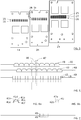
- the figure 2 gives an example of device 7 according to the invention with three modules.
- the first module 10 is intended, particularly in this case, to produce first unit beams. It comprises a support on which are reported lenses 12 forming optical elements for light sources. The lenses 12 are organized in rows, as well as the corresponding sources, as detailed below.
- an optical field element 13 which may be a biconvex lens.
- the figure 2 also gives a representation of components which may be similar for a second module 20: support 21, lenses 22 and optical field element 23.
- the third module 30 support 31, lenses 32 and optical field element 33.
- the three modules 10, 20, 30 share one and the same optical element (typically a projection lens).
- the modules in question are also visible from above in figure 3 .
- the light produced by a light source of a module is first shaped by a lens of the module, then by the field lens and is finally projected by the element 8.
- the light sources are therefore each associated with an optical element (a lens 12, 22, 32) so as to form in combination an illumination unit producing a unitary beam of a shape defined by the optical element.
- FIGs 4, 4a and 5 The organization of lenses and light sources is apparent Figures 4, 4a and 5 especially.
- FIG 4 the front face of the lenses 12, 22, 32 is shown. These lenses are located downstream of light sources (masked in figure 4 ) but carried by the electronic cards 14, 24, 34 which are visible.
- For the first module 10 two rows of lenses 12 are visible, in superposition. Similar rows are formed for the third module.
- the second module 20 comprises three rows of lenses 32 superimposed.
- each optical element comprises or is a lens, and preferably a microlens.
- the microlens preferably have dimensions of substantially the same order of magnitude as those of an LED.
- the lens is a spherical lens, a focus of which is disposed behind the LED array. This advantageously makes it possible to generate an enlarged virtual image behind the LED matrix and which is projected by an infinite projection element.
- the projection element at infinity can image the exit surface of the lens.
- the figure 4a gives an example of the shape of these lenses or more generally of these optical elements.
- a row of first optical elements 17 is organized with a shape conferring the cutoff slopes.
- a further row of additional optical elements is also present, to provide additional beams, especially for a portion of a driving beam, in a matrix beam function called "matrix beam" in English.
- the elements 17 and 18 are of the same number and are associated in pairs so as to be aligned vertically; each pair of elements 17, 18 having a rectangular envelope and the element 18 constituting the counter-shape of the element 17 here trapezoidal portion. They are preferably made in one piece, from a single material, such as PMMA.
- the lenses forming the second optical elements of the figure 4 are generally simpler form because the beam shapes are here preferably rectangular (which includes square shapes).
- their width is half that of the lenses of the other modules (for the less the lenses 22 of the second unitary beams are half as wide as the lenses 12 and 32). We will see that this choice of dimensions ensures a particular distribution of projected beams.
- the figure 5 shows the organization of the light sources of the three modules 10, 20, 30.
- the first module 10 comprises a row of first sources 15 in the form of LEDs aligned laterally.
- a row of additional LEDs 16 is in correspondence with the row of elements 18.
- the third module 30 comprises a row of third sources 35 and a row of additional sources 36, respectively in association with the row of third optical elements. 37 and with the third row of additional optical elements 38.
- the second module 20 comprising three rows of optical elements in this embodiment, it comprises in correspondence three rows of light sources. Row 25 makes it possible to produce the second unitary beams.
- the second row 26 produces unit beams of "matrix beam" as in the case of the rows 16 and 36.
- the row 27 produces unit beams, in association with the third row of optical elements of the second module, for a function of additional lighting, for example a marking line function.
- the row 27 is located above the row 25, opposite the row 26.
- At least the row 25 of the second module 20 has a double resolution (a step in half between the sources) of the sources forming the sloping beams.
- the Figures 6 to 11 illustrate the illuminations that can be produced by the invention.
- the figure 6 presents the result of a projection on the assumption that all the first, second and third unitary beams are projected simultaneously in addition to all the marking beams.
- the first line illustrates the first unit beams each forming a first beam pixel 41 from the first module 10.
- This pixel 41 comprises a trapezoidal upper portion forming the slope portion of the unitary beam.
- the trapezium is isosceles and / or the slope of at least one lateral side is 45 ° relative to the horizon line.
- the upper portion is preferably at least partly and possibly totally projected above the horizon line 40.
- Another pixel portion 41 is generated at the base of the trapezoid in the form of a rectangle forming part of the continuity from the large base of the trapeze.
- the row of pixels 41 may be symmetrical around a central pixel 41 by the middle of which passes a vertical axis 46 of average projection.
- the second line shows pixels 43 of unit beams of identical shape to that of the pixels 41. These beams are third beams generated by the third module 30.
- the pixels 43 are nonetheless laterally offset relative to the pixels 41, with a shift pitch 47 corresponding advantageously to the length of the small base, upper base, of the trapezoidal portion of the unitary beams.
- the third line has pixels 42, 44 produced by the second module 20.
- the pixels 42 correspond to the second unit beams previously described and the pixels 44 to marking line function pixels. These are preferably rectangles in the continuity down of the pixels of second unitary beams.
- the figure 6 further shows that one pixel out of two is advantageously aligned on the small base of a trapezium with respect to one of the rows of pixels 41, 43 (the pixel line 41 in the figure 6 and preferably the small base of the trapeziums coincides with the upper side of the pixel 42 corresponding to this alignment.
- the other pixels 42 are preferably aligned on the small base of a pixel trapezoid 43.
- the height of the portion of the pixels 42 located above the horizon line 40 is identical to the height of the portion
- the pixel line 42 is advantageously symmetrical about the line 46. There may be nine pixels 41, 43 and nineteen pixels 42.
- the shape of a pixel 41 (advantageously identical to that of the pixels 43) is given in detail in FIG. figure 6a .
- the upper portion 41a is a trapezium whose lateral edges 41b and 41c are symmetrical.
- the inclination is here at 45 ° so that the width of the first base 41d, small base, is half that of the second base 41e, large base.
- the first base 41d forms the vertex of the shape of the first unitary beam.
- the pixel 41 here comprises a rectangular lower portion whose second base 41e forms an upper edge.
- the 41st base is here located on the horizon line. It is not absolutely necessary according to the invention that the pixel 41 has a lower portion; in particular, the pixel 41 may consist of the upper portion only.
- the lower portion may however soften the transition between the pixel 41 and another portion of the beam, in particular the edge of a so-called "flat" or flat beam, complementary to the pixels 41, 42, 43 activated to form a full beam of passing beam.
- the trapezoidal shape is not limiting and other shapes with at least one slope could be used on a lateral edge, for example a triangle, possibly isosceles.
- the figure 6b gives an example of second pixel 42.
- This is a square of sides 42a, 42b of identical length to the width of the first base 41d. This dimension is preferably also equal to the height of the first pixel 41.
- This shape defines an upper edge which may coincide with the first base of the trapezium. In general, it is arranged for a corner of the rectangular shape fits on one of the ends of the top of the sloping form (preferably the trapezium).
- the low beam function only a portion of the pixels 41, 42, 43 are illuminated so as to produce a high beam portion of the crossing light beam. This is one of the pixels 41, 43 that will define the break; the other pixels 41, 43 are preferably then extinguished.
- a pixel 42 coinciding with the first base of the two active pixels 41, 43 is also activated.
- at least one other pixel 42, in the continuity of the pixel 42 in question is also activated, to form a set of pixels 42 active in the continuity of the cutoff slope defined by the pixel 41, 43 active.
- the cutoff 48 is given by one of the trapezoidal edges of the pixel 41, 43 active.
- the remainder of the resulting beam is given by pixels 42; there is some overlap between active pixels 42 and pixel 41, 43.
- the lighting device also comprises means for controlling the illumination of the LED matrix with a sensor of a trajectory parameter of a motor vehicle.
- the sensor advantageously provides an angle of rotation of a steering wheel of the motor vehicle, the trajectory parameter indicating a deviation of a road on which the vehicle travels relative to a straight line, such as, in particular, a turn.
- the present invention has the advantage of being able to generate a light beam for dipped beam whose cutoff follows the path of the vehicle on a sinuous road, because of a discretization of the beam in portions of the type of successive isosceles trapezes.
- the discretization according to the present invention also allows adaptation to a right-hand drive vehicle as well as a left-hand drive vehicle, and even allows a right or left drive change for a given vehicle.
- the discretization in sloping shapes, and particularly in trapezes, also makes it possible to adapt to a non glaring high beam for another vehicle.
- the present invention makes it possible to perform various functions, such as: directional low beam, left and right steering, and non-glare high beam.
- figure 8 An example of placement of the cut-off beam zone permitted by the invention is given in figure 8 .
- the figure 9 gives an example of a complete beam of dipped beam, resulting from the combination of the portion obtained in figure 8 by the modules 10, 20, 30 with a complementary low beam of the "flat" type.
- the modules 10, 20, 30 can also be used to generate other beams, in a matrix of beams.
- the figure 10 schematizes the definition of additional additional unit beams with pixels 51, 52, 53. These latter make it possible to generate an upper part of a complete beam, for example to produce a high beam by simultaneously lighting the pixels 41, 42, 43 51, 52, 53 are respectively in continuity and above a pixel 41, 42, 43 figure 10 also presents the marking line function with the pixels 44 this time directed below the horizon line 40.
- the figure 11 presents the shape of a driving beam resulting from the illumination of pixels 41, 42, 43, 51, 52, 53.
- not all pixels may be simultaneously activated to isolate a section of the light in the form of a vertical strip , for example for an anti-glare vignetting function.
- two adjacent pixels 41, two adjacent pixels 43 and two adjacent pixels 42 can be deactivated so as not to illuminate an area of width corresponding to two pixels 42.
- the illumination extends 5 degrees above the line d 'horizon.
- the lateral angular sector is 41 degrees with 23 degrees on the unlit side up (here left side) and 18 degrees on the right side.
Landscapes
- Engineering & Computer Science (AREA)
- General Engineering & Computer Science (AREA)
- Physics & Mathematics (AREA)
- Microelectronics & Electronic Packaging (AREA)
- Optics & Photonics (AREA)
- Mathematical Physics (AREA)
- Non-Portable Lighting Devices Or Systems Thereof (AREA)
- Lighting Device Outwards From Vehicle And Optical Signal (AREA)
Applications Claiming Priority (1)
| Application Number | Priority Date | Filing Date | Title |
|---|---|---|---|
| FR1851731A FR3078381B1 (fr) | 2018-02-27 | 2018-02-27 | Dispositif lumineux pour vehicule automobile, et unite d'eclairage et/ou de signalisation muni d'un tel dispositif |
Publications (2)
| Publication Number | Publication Date |
|---|---|
| EP3531010A1 true EP3531010A1 (de) | 2019-08-28 |
| EP3531010B1 EP3531010B1 (de) | 2021-03-10 |
Family
ID=62222936
Family Applications (1)
| Application Number | Title | Priority Date | Filing Date |
|---|---|---|---|
| EP19158960.5A Active EP3531010B1 (de) | 2018-02-27 | 2019-02-22 | Leuchtvorrichtung für kraftfahrzeug und beleuchtungs- und/oder signalisierungseinheit, die mit einer solchen vorrichtung ausgestattet ist |
Country Status (4)
| Country | Link |
|---|---|
| US (1) | US10605425B2 (de) |
| EP (1) | EP3531010B1 (de) |
| CN (1) | CN110195845B (de) |
| FR (1) | FR3078381B1 (de) |
Cited By (1)
| Publication number | Priority date | Publication date | Assignee | Title |
|---|---|---|---|---|
| EP3550204B1 (de) * | 2018-04-03 | 2023-05-17 | Valeo Vision | Leuchtvorrichtung für kraftfahrzeug, die eine schreibfunktion auf dem boden ausführt |
Families Citing this family (2)
| Publication number | Priority date | Publication date | Assignee | Title |
|---|---|---|---|---|
| KR20210144483A (ko) * | 2020-05-22 | 2021-11-30 | 삼성전자주식회사 | 발광 장치 및 운송 수단용 헤드램프 |
| CN113639248A (zh) * | 2021-08-19 | 2021-11-12 | 深圳市希尔光学技术有限公司 | 一种德规自行车光学透镜 |
Citations (6)
| Publication number | Priority date | Publication date | Assignee | Title |
|---|---|---|---|---|
| EP2306075A2 (de) * | 2009-10-05 | 2011-04-06 | Automotive Lighting Reutlingen GmbH | Zur Erzeugung verschiedener Lichtverteilungen eingerichteter Kraftfahrzeugscheinwerfer mit Halbleiterlichtquellen |
| DE102013113148A1 (de) * | 2013-11-28 | 2015-05-28 | Hella Kgaa Hueck & Co. | Beleuchtungsvorrichtung für Fahrzeuge |
| DE102014110282A1 (de) * | 2014-07-22 | 2016-01-28 | Hella Kgaa Hueck & Co. | Beleuchtungsvorrichtung für Fahrzeuge |
| JP2016212962A (ja) * | 2015-04-30 | 2016-12-15 | 日亜化学工業株式会社 | 照明装置 |
| JP2017174830A (ja) * | 2017-06-27 | 2017-09-28 | 株式会社小糸製作所 | 灯具ユニット |
| JP2017224468A (ja) * | 2016-06-15 | 2017-12-21 | 株式会社小糸製作所 | 車両用灯具 |
Family Cites Families (16)
| Publication number | Priority date | Publication date | Assignee | Title |
|---|---|---|---|---|
| JP4024628B2 (ja) * | 2002-09-03 | 2007-12-19 | 株式会社小糸製作所 | 車両用前照灯 |
| JP4428223B2 (ja) * | 2004-12-07 | 2010-03-10 | 市光工業株式会社 | 車両用灯具および車両用前照灯装置 |
| FR2936458B1 (fr) * | 2008-09-26 | 2011-08-05 | Valeo Vision Sas | Systeme d'eclairage pour vehicule automobile apte a modifier l'emission d'un faisceau lumineux de type code |
| JP5352263B2 (ja) * | 2009-02-06 | 2013-11-27 | 株式会社小糸製作所 | 車両用灯具 |
| DE102010029176A1 (de) * | 2009-10-05 | 2012-12-27 | Automotive Lighting Reutlingen Gmbh | Kraftfahrzeugscheinwerfer mit einem Halbleiterlichtquellen, eine Primäroptik und eine Sekundäroptik aufweisenden Lichtmodul |
| JP5582865B2 (ja) * | 2010-05-12 | 2014-09-03 | 株式会社小糸製作所 | 灯具 |
| CN102330948B (zh) * | 2011-08-31 | 2014-09-10 | 华南理工大学 | Led汽车照明用反射器及组合式前照灯 |
| FR3002303B1 (fr) * | 2013-02-21 | 2015-03-20 | Valeo Vision | Unite d'eclairage et/ou de signalisation notamment de vehicule automobile |
| US9222637B2 (en) * | 2013-03-14 | 2015-12-29 | Valeo North America, Inc. | Lightguide with horizontal cutoff and horizontal spread |
| KR102004686B1 (ko) * | 2013-04-08 | 2019-07-29 | 현대모비스 주식회사 | 컷오프 라인을 구현하는 멀티 어레이 엘이디 칩 및 이를 구비하는 헤드 램프 |
| JP2015015104A (ja) * | 2013-07-03 | 2015-01-22 | スタンレー電気株式会社 | 光源装置、車両用前照灯、車両用前照灯システム |
| JP6271181B2 (ja) * | 2013-08-06 | 2018-01-31 | 株式会社小糸製作所 | 車両用灯具 |
| US9873372B2 (en) * | 2014-12-19 | 2018-01-23 | Sl Corporation | Adaptive driving beam headlamp for vehicle |
| CN105485597B (zh) * | 2015-11-05 | 2019-01-11 | 格瑞电子(厦门)有限公司 | 一种基于led的前照灯及远近光斑的形成方法 |
| CN206268978U (zh) * | 2016-09-30 | 2017-06-20 | 马瑞利汽车零部件(芜湖)有限公司 | 使用透镜实现近光的汽车前照灯光学系统 |
| CN107062123B (zh) * | 2017-03-01 | 2023-04-14 | 华域视觉科技(上海)有限公司 | 一种用于汽车车灯的投射式光学照明系统 |
-
2018
- 2018-02-27 FR FR1851731A patent/FR3078381B1/fr not_active Expired - Fee Related
-
2019
- 2019-02-22 EP EP19158960.5A patent/EP3531010B1/de active Active
- 2019-02-27 US US16/287,230 patent/US10605425B2/en active Active
- 2019-02-27 CN CN201910148451.2A patent/CN110195845B/zh active Active
Patent Citations (6)
| Publication number | Priority date | Publication date | Assignee | Title |
|---|---|---|---|---|
| EP2306075A2 (de) * | 2009-10-05 | 2011-04-06 | Automotive Lighting Reutlingen GmbH | Zur Erzeugung verschiedener Lichtverteilungen eingerichteter Kraftfahrzeugscheinwerfer mit Halbleiterlichtquellen |
| DE102013113148A1 (de) * | 2013-11-28 | 2015-05-28 | Hella Kgaa Hueck & Co. | Beleuchtungsvorrichtung für Fahrzeuge |
| DE102014110282A1 (de) * | 2014-07-22 | 2016-01-28 | Hella Kgaa Hueck & Co. | Beleuchtungsvorrichtung für Fahrzeuge |
| JP2016212962A (ja) * | 2015-04-30 | 2016-12-15 | 日亜化学工業株式会社 | 照明装置 |
| JP2017224468A (ja) * | 2016-06-15 | 2017-12-21 | 株式会社小糸製作所 | 車両用灯具 |
| JP2017174830A (ja) * | 2017-06-27 | 2017-09-28 | 株式会社小糸製作所 | 灯具ユニット |
Cited By (1)
| Publication number | Priority date | Publication date | Assignee | Title |
|---|---|---|---|---|
| EP3550204B1 (de) * | 2018-04-03 | 2023-05-17 | Valeo Vision | Leuchtvorrichtung für kraftfahrzeug, die eine schreibfunktion auf dem boden ausführt |
Also Published As
| Publication number | Publication date |
|---|---|
| US20190264884A1 (en) | 2019-08-29 |
| FR3078381A1 (fr) | 2019-08-30 |
| US10605425B2 (en) | 2020-03-31 |
| CN110195845B (zh) | 2022-09-27 |
| CN110195845A (zh) | 2019-09-03 |
| FR3078381B1 (fr) | 2020-08-14 |
| EP3531010B1 (de) | 2021-03-10 |
Similar Documents
| Publication | Publication Date | Title |
|---|---|---|
| EP3521691B1 (de) | Leuchtmodul für kraftfahrzeug, und beleuchtungs- und/oder signalisierungsvorrichtung, die mit einem solchen modul ausgestattet ist | |
| EP3350019B1 (de) | Beleuchtungssystem für kraftfahrzeuge | |
| EP2690352B1 (de) | Adaptives Beleuchtungssystem für Kraftfahrzeug | |
| EP2278217B1 (de) | Beleuchtungsmodul für Fahrzeugscheinwerfer, und mit wenigstens einem solchen Modul ausgerüsteter Scheinwerfer | |
| EP3115256A1 (de) | Kontrollverfahren eines lichtbündels, und entsprechendes beleuchtungs- und/oder signalisierungsmodul | |
| FR2995967B1 (fr) | Module d'eclairage, notamment pour vehicule automobile | |
| EP3027961B1 (de) | Beleuchtungssystem für ein kraftfahrzeug | |
| EP2813395A1 (de) | Kraftfahrzeug-Scheinwerfer, der eine Laser-Lichtquelle umfasst und Verfahren zur Erzeugung eines Lichtbündel | |
| EP3531010B1 (de) | Leuchtvorrichtung für kraftfahrzeug und beleuchtungs- und/oder signalisierungseinheit, die mit einer solchen vorrichtung ausgestattet ist | |
| FR2963589A1 (fr) | Systeme d'eclairage pour vehicule | |
| EP3267096A1 (de) | Vorrichtung zur beleuchtung und/oder signalisierung für kraftfahrzeuge | |
| EP3350507B1 (de) | Beleuchtungsvorrichtung für kraftfahrzeuge | |
| EP3030830B1 (de) | Signalisierungs- und/oder beleuchtungsvorrichtung für kraftfahrzeuge | |
| EP2068071A1 (de) | Verfahren zur automatischen Anpassung des Lichtstrahls eines optischen Moduls an die Bedingungen des Straßenverkehrs, und entsprechender Fahrzeugscheinwerfer | |
| FR3006421A1 (fr) | Module d'eclairage pour projecteur de vehicule automobile, projecteur equipe de tels modules, et ensemble de projecteurs | |
| EP3453946A1 (de) | Leuchtmodul für kraftfahrzeug, und beleuchtungs- und/oder signalisierungsvorrichtung, die mit einem solchen modul ausgestattet ist | |
| FR2916036A1 (fr) | Projecteur de vehicule | |
| EP3455102B1 (de) | Beleuchtungssystem und verfahren für ein kraftfahrzeug | |
| FR3042844A1 (fr) | Systeme d'eclairage pour vehicules automobiles | |
| EP3436307B1 (de) | Fahrzeugscheinwerfer | |
| WO2026057748A1 (fr) | Module lumineux d'un dispositif d'éclairage d'un véhicule automobile | |
| FR3144247A1 (fr) | Dispositif lumineux comprenant une pluralité de modules | |
| EP1953039A2 (de) | Multifunktionsbeleuchtungsvorrichtung für Kraftfahrzeug |
Legal Events
| Date | Code | Title | Description |
|---|---|---|---|
| PUAI | Public reference made under article 153(3) epc to a published international application that has entered the european phase |
Free format text: ORIGINAL CODE: 0009012 |
|
| STAA | Information on the status of an ep patent application or granted ep patent |
Free format text: STATUS: REQUEST FOR EXAMINATION WAS MADE |
|
| 17P | Request for examination filed |
Effective date: 20190222 |
|
| AK | Designated contracting states |
Kind code of ref document: A1 Designated state(s): AL AT BE BG CH CY CZ DE DK EE ES FI FR GB GR HR HU IE IS IT LI LT LU LV MC MK MT NL NO PL PT RO RS SE SI SK SM TR |
|
| AX | Request for extension of the european patent |
Extension state: BA ME |
|
| GRAP | Despatch of communication of intention to grant a patent |
Free format text: ORIGINAL CODE: EPIDOSNIGR1 |
|
| STAA | Information on the status of an ep patent application or granted ep patent |
Free format text: STATUS: GRANT OF PATENT IS INTENDED |
|
| INTG | Intention to grant announced |
Effective date: 20201002 |
|
| RIN1 | Information on inventor provided before grant (corrected) |
Inventor name: GROMFELD, YVES |
|
| GRAS | Grant fee paid |
Free format text: ORIGINAL CODE: EPIDOSNIGR3 |
|
| GRAA | (expected) grant |
Free format text: ORIGINAL CODE: 0009210 |
|
| STAA | Information on the status of an ep patent application or granted ep patent |
Free format text: STATUS: THE PATENT HAS BEEN GRANTED |
|
| AK | Designated contracting states |
Kind code of ref document: B1 Designated state(s): AL AT BE BG CH CY CZ DE DK EE ES FI FR GB GR HR HU IE IS IT LI LT LU LV MC MK MT NL NO PL PT RO RS SE SI SK SM TR |
|
| REG | Reference to a national code |
Ref country code: GB Ref legal event code: FG4D Free format text: NOT ENGLISH |
|
| REG | Reference to a national code |
Ref country code: CH Ref legal event code: EP Ref country code: AT Ref legal event code: REF Ref document number: 1370192 Country of ref document: AT Kind code of ref document: T Effective date: 20210315 |
|
| REG | Reference to a national code |
Ref country code: IE Ref legal event code: FG4D Free format text: LANGUAGE OF EP DOCUMENT: FRENCH |
|
| REG | Reference to a national code |
Ref country code: DE Ref legal event code: R096 Ref document number: 602019003003 Country of ref document: DE |
|
| REG | Reference to a national code |
Ref country code: LT Ref legal event code: MG9D |
|
| PG25 | Lapsed in a contracting state [announced via postgrant information from national office to epo] |
Ref country code: NO Free format text: LAPSE BECAUSE OF FAILURE TO SUBMIT A TRANSLATION OF THE DESCRIPTION OR TO PAY THE FEE WITHIN THE PRESCRIBED TIME-LIMIT Effective date: 20210610 Ref country code: LT Free format text: LAPSE BECAUSE OF FAILURE TO SUBMIT A TRANSLATION OF THE DESCRIPTION OR TO PAY THE FEE WITHIN THE PRESCRIBED TIME-LIMIT Effective date: 20210310 Ref country code: BG Free format text: LAPSE BECAUSE OF FAILURE TO SUBMIT A TRANSLATION OF THE DESCRIPTION OR TO PAY THE FEE WITHIN THE PRESCRIBED TIME-LIMIT Effective date: 20210610 Ref country code: HR Free format text: LAPSE BECAUSE OF FAILURE TO SUBMIT A TRANSLATION OF THE DESCRIPTION OR TO PAY THE FEE WITHIN THE PRESCRIBED TIME-LIMIT Effective date: 20210310 Ref country code: FI Free format text: LAPSE BECAUSE OF FAILURE TO SUBMIT A TRANSLATION OF THE DESCRIPTION OR TO PAY THE FEE WITHIN THE PRESCRIBED TIME-LIMIT Effective date: 20210310 Ref country code: GR Free format text: LAPSE BECAUSE OF FAILURE TO SUBMIT A TRANSLATION OF THE DESCRIPTION OR TO PAY THE FEE WITHIN THE PRESCRIBED TIME-LIMIT Effective date: 20210611 |
|
| REG | Reference to a national code |
Ref country code: AT Ref legal event code: MK05 Ref document number: 1370192 Country of ref document: AT Kind code of ref document: T Effective date: 20210310 |
|
| REG | Reference to a national code |
Ref country code: NL Ref legal event code: MP Effective date: 20210310 |
|
| PG25 | Lapsed in a contracting state [announced via postgrant information from national office to epo] |
Ref country code: LV Free format text: LAPSE BECAUSE OF FAILURE TO SUBMIT A TRANSLATION OF THE DESCRIPTION OR TO PAY THE FEE WITHIN THE PRESCRIBED TIME-LIMIT Effective date: 20210310 Ref country code: RS Free format text: LAPSE BECAUSE OF FAILURE TO SUBMIT A TRANSLATION OF THE DESCRIPTION OR TO PAY THE FEE WITHIN THE PRESCRIBED TIME-LIMIT Effective date: 20210310 Ref country code: SE Free format text: LAPSE BECAUSE OF FAILURE TO SUBMIT A TRANSLATION OF THE DESCRIPTION OR TO PAY THE FEE WITHIN THE PRESCRIBED TIME-LIMIT Effective date: 20210310 |
|
| PG25 | Lapsed in a contracting state [announced via postgrant information from national office to epo] |
Ref country code: NL Free format text: LAPSE BECAUSE OF FAILURE TO SUBMIT A TRANSLATION OF THE DESCRIPTION OR TO PAY THE FEE WITHIN THE PRESCRIBED TIME-LIMIT Effective date: 20210310 |
|
| PG25 | Lapsed in a contracting state [announced via postgrant information from national office to epo] |
Ref country code: EE Free format text: LAPSE BECAUSE OF FAILURE TO SUBMIT A TRANSLATION OF THE DESCRIPTION OR TO PAY THE FEE WITHIN THE PRESCRIBED TIME-LIMIT Effective date: 20210310 Ref country code: CZ Free format text: LAPSE BECAUSE OF FAILURE TO SUBMIT A TRANSLATION OF THE DESCRIPTION OR TO PAY THE FEE WITHIN THE PRESCRIBED TIME-LIMIT Effective date: 20210310 Ref country code: AT Free format text: LAPSE BECAUSE OF FAILURE TO SUBMIT A TRANSLATION OF THE DESCRIPTION OR TO PAY THE FEE WITHIN THE PRESCRIBED TIME-LIMIT Effective date: 20210310 Ref country code: SM Free format text: LAPSE BECAUSE OF FAILURE TO SUBMIT A TRANSLATION OF THE DESCRIPTION OR TO PAY THE FEE WITHIN THE PRESCRIBED TIME-LIMIT Effective date: 20210310 |
|
| PG25 | Lapsed in a contracting state [announced via postgrant information from national office to epo] |
Ref country code: IS Free format text: LAPSE BECAUSE OF FAILURE TO SUBMIT A TRANSLATION OF THE DESCRIPTION OR TO PAY THE FEE WITHIN THE PRESCRIBED TIME-LIMIT Effective date: 20210710 Ref country code: PL Free format text: LAPSE BECAUSE OF FAILURE TO SUBMIT A TRANSLATION OF THE DESCRIPTION OR TO PAY THE FEE WITHIN THE PRESCRIBED TIME-LIMIT Effective date: 20210310 Ref country code: SK Free format text: LAPSE BECAUSE OF FAILURE TO SUBMIT A TRANSLATION OF THE DESCRIPTION OR TO PAY THE FEE WITHIN THE PRESCRIBED TIME-LIMIT Effective date: 20210310 Ref country code: PT Free format text: LAPSE BECAUSE OF FAILURE TO SUBMIT A TRANSLATION OF THE DESCRIPTION OR TO PAY THE FEE WITHIN THE PRESCRIBED TIME-LIMIT Effective date: 20210712 Ref country code: RO Free format text: LAPSE BECAUSE OF FAILURE TO SUBMIT A TRANSLATION OF THE DESCRIPTION OR TO PAY THE FEE WITHIN THE PRESCRIBED TIME-LIMIT Effective date: 20210310 |
|
| REG | Reference to a national code |
Ref country code: DE Ref legal event code: R097 Ref document number: 602019003003 Country of ref document: DE |
|
| PLBE | No opposition filed within time limit |
Free format text: ORIGINAL CODE: 0009261 |
|
| STAA | Information on the status of an ep patent application or granted ep patent |
Free format text: STATUS: NO OPPOSITION FILED WITHIN TIME LIMIT |
|
| PG25 | Lapsed in a contracting state [announced via postgrant information from national office to epo] |
Ref country code: ES Free format text: LAPSE BECAUSE OF FAILURE TO SUBMIT A TRANSLATION OF THE DESCRIPTION OR TO PAY THE FEE WITHIN THE PRESCRIBED TIME-LIMIT Effective date: 20210310 Ref country code: DK Free format text: LAPSE BECAUSE OF FAILURE TO SUBMIT A TRANSLATION OF THE DESCRIPTION OR TO PAY THE FEE WITHIN THE PRESCRIBED TIME-LIMIT Effective date: 20210310 Ref country code: AL Free format text: LAPSE BECAUSE OF FAILURE TO SUBMIT A TRANSLATION OF THE DESCRIPTION OR TO PAY THE FEE WITHIN THE PRESCRIBED TIME-LIMIT Effective date: 20210310 |
|
| 26N | No opposition filed |
Effective date: 20211213 |
|
| PG25 | Lapsed in a contracting state [announced via postgrant information from national office to epo] |
Ref country code: SI Free format text: LAPSE BECAUSE OF FAILURE TO SUBMIT A TRANSLATION OF THE DESCRIPTION OR TO PAY THE FEE WITHIN THE PRESCRIBED TIME-LIMIT Effective date: 20210310 |
|
| PG25 | Lapsed in a contracting state [announced via postgrant information from national office to epo] |
Ref country code: IT Free format text: LAPSE BECAUSE OF FAILURE TO SUBMIT A TRANSLATION OF THE DESCRIPTION OR TO PAY THE FEE WITHIN THE PRESCRIBED TIME-LIMIT Effective date: 20210310 |
|
| PG25 | Lapsed in a contracting state [announced via postgrant information from national office to epo] |
Ref country code: IS Free format text: LAPSE BECAUSE OF FAILURE TO SUBMIT A TRANSLATION OF THE DESCRIPTION OR TO PAY THE FEE WITHIN THE PRESCRIBED TIME-LIMIT Effective date: 20210710 |
|
| PG25 | Lapsed in a contracting state [announced via postgrant information from national office to epo] |
Ref country code: MC Free format text: LAPSE BECAUSE OF FAILURE TO SUBMIT A TRANSLATION OF THE DESCRIPTION OR TO PAY THE FEE WITHIN THE PRESCRIBED TIME-LIMIT Effective date: 20210310 |
|
| REG | Reference to a national code |
Ref country code: CH Ref legal event code: PL |
|
| REG | Reference to a national code |
Ref country code: BE Ref legal event code: MM Effective date: 20220228 |
|
| PG25 | Lapsed in a contracting state [announced via postgrant information from national office to epo] |
Ref country code: LU Free format text: LAPSE BECAUSE OF NON-PAYMENT OF DUE FEES Effective date: 20220222 |
|
| PG25 | Lapsed in a contracting state [announced via postgrant information from national office to epo] |
Ref country code: LI Free format text: LAPSE BECAUSE OF NON-PAYMENT OF DUE FEES Effective date: 20220228 Ref country code: IE Free format text: LAPSE BECAUSE OF NON-PAYMENT OF DUE FEES Effective date: 20220222 Ref country code: CH Free format text: LAPSE BECAUSE OF NON-PAYMENT OF DUE FEES Effective date: 20220228 |
|
| PG25 | Lapsed in a contracting state [announced via postgrant information from national office to epo] |
Ref country code: BE Free format text: LAPSE BECAUSE OF NON-PAYMENT OF DUE FEES Effective date: 20220228 |
|
| P01 | Opt-out of the competence of the unified patent court (upc) registered |
Effective date: 20230528 |
|
| GBPC | Gb: european patent ceased through non-payment of renewal fee |
Effective date: 20230222 |
|
| PG25 | Lapsed in a contracting state [announced via postgrant information from national office to epo] |
Ref country code: GB Free format text: LAPSE BECAUSE OF NON-PAYMENT OF DUE FEES Effective date: 20230222 |
|
| PG25 | Lapsed in a contracting state [announced via postgrant information from national office to epo] |
Ref country code: GB Free format text: LAPSE BECAUSE OF NON-PAYMENT OF DUE FEES Effective date: 20230222 |
|
| PG25 | Lapsed in a contracting state [announced via postgrant information from national office to epo] |
Ref country code: MK Free format text: LAPSE BECAUSE OF FAILURE TO SUBMIT A TRANSLATION OF THE DESCRIPTION OR TO PAY THE FEE WITHIN THE PRESCRIBED TIME-LIMIT Effective date: 20210310 Ref country code: CY Free format text: LAPSE BECAUSE OF FAILURE TO SUBMIT A TRANSLATION OF THE DESCRIPTION OR TO PAY THE FEE WITHIN THE PRESCRIBED TIME-LIMIT Effective date: 20210310 |
|
| PG25 | Lapsed in a contracting state [announced via postgrant information from national office to epo] |
Ref country code: HU Free format text: LAPSE BECAUSE OF FAILURE TO SUBMIT A TRANSLATION OF THE DESCRIPTION OR TO PAY THE FEE WITHIN THE PRESCRIBED TIME-LIMIT; INVALID AB INITIO Effective date: 20190222 |
|
| PG25 | Lapsed in a contracting state [announced via postgrant information from national office to epo] |
Ref country code: MT Free format text: LAPSE BECAUSE OF FAILURE TO SUBMIT A TRANSLATION OF THE DESCRIPTION OR TO PAY THE FEE WITHIN THE PRESCRIBED TIME-LIMIT Effective date: 20210310 |
|
| PG25 | Lapsed in a contracting state [announced via postgrant information from national office to epo] |
Ref country code: TR Free format text: LAPSE BECAUSE OF FAILURE TO SUBMIT A TRANSLATION OF THE DESCRIPTION OR TO PAY THE FEE WITHIN THE PRESCRIBED TIME-LIMIT Effective date: 20210310 |
|
| PGFP | Annual fee paid to national office [announced via postgrant information from national office to epo] |
Ref country code: DE Payment date: 20260206 Year of fee payment: 8 |
|
| PGFP | Annual fee paid to national office [announced via postgrant information from national office to epo] |
Ref country code: FR Payment date: 20260227 Year of fee payment: 8 |