EP3530809B1 - Verbindungsstruktur für eine meeresinstallation - Google Patents
Verbindungsstruktur für eine meeresinstallation Download PDFInfo
- Publication number
- EP3530809B1 EP3530809B1 EP18157798.2A EP18157798A EP3530809B1 EP 3530809 B1 EP3530809 B1 EP 3530809B1 EP 18157798 A EP18157798 A EP 18157798A EP 3530809 B1 EP3530809 B1 EP 3530809B1
- Authority
- EP
- European Patent Office
- Prior art keywords
- connection structure
- connection
- seabed
- spatial region
- superstructure
- Prior art date
- Legal status (The legal status is an assumption and is not a legal conclusion. Google has not performed a legal analysis and makes no representation as to the accuracy of the status listed.)
- Active
Links
Images


Classifications
-
- E—FIXED CONSTRUCTIONS
- E02—HYDRAULIC ENGINEERING; FOUNDATIONS; SOIL SHIFTING
- E02B—HYDRAULIC ENGINEERING
- E02B17/00—Artificial islands mounted on piles or like supports, e.g. platforms on raisable legs or offshore constructions; Construction methods therefor
-
- E—FIXED CONSTRUCTIONS
- E02—HYDRAULIC ENGINEERING; FOUNDATIONS; SOIL SHIFTING
- E02B—HYDRAULIC ENGINEERING
- E02B17/00—Artificial islands mounted on piles or like supports, e.g. platforms on raisable legs or offshore constructions; Construction methods therefor
- E02B17/0004—Nodal points
-
- E—FIXED CONSTRUCTIONS
- E02—HYDRAULIC ENGINEERING; FOUNDATIONS; SOIL SHIFTING
- E02B—HYDRAULIC ENGINEERING
- E02B17/00—Artificial islands mounted on piles or like supports, e.g. platforms on raisable legs or offshore constructions; Construction methods therefor
- E02B17/02—Artificial islands mounted on piles or like supports, e.g. platforms on raisable legs or offshore constructions; Construction methods therefor placed by lowering the supporting construction to the bottom, e.g. with subsequent fixing thereto
- E02B17/027—Artificial islands mounted on piles or like supports, e.g. platforms on raisable legs or offshore constructions; Construction methods therefor placed by lowering the supporting construction to the bottom, e.g. with subsequent fixing thereto steel structures
-
- E—FIXED CONSTRUCTIONS
- E02—HYDRAULIC ENGINEERING; FOUNDATIONS; SOIL SHIFTING
- E02D—FOUNDATIONS; EXCAVATIONS; EMBANKMENTS; UNDERGROUND OR UNDERWATER STRUCTURES
- E02D27/00—Foundations as substructures
- E02D27/10—Deep foundations
- E02D27/12—Pile foundations
- E02D27/16—Foundations formed of separate piles
-
- E—FIXED CONSTRUCTIONS
- E02—HYDRAULIC ENGINEERING; FOUNDATIONS; SOIL SHIFTING
- E02D—FOUNDATIONS; EXCAVATIONS; EMBANKMENTS; UNDERGROUND OR UNDERWATER STRUCTURES
- E02D27/00—Foundations as substructures
- E02D27/32—Foundations for special purposes
- E02D27/52—Submerged foundations, i.e. submerged in open water
- E02D27/525—Submerged foundations, i.e. submerged in open water using elements penetrating the underwater ground
-
- F—MECHANICAL ENGINEERING; LIGHTING; HEATING; WEAPONS; BLASTING
- F03—MACHINES OR ENGINES FOR LIQUIDS; WIND, SPRING, OR WEIGHT MOTORS; PRODUCING MECHANICAL POWER OR A REACTIVE PROPULSIVE THRUST, NOT OTHERWISE PROVIDED FOR
- F03D—WIND MOTORS
- F03D80/00—Details, components or accessories not provided for in groups F03D1/00 - F03D17/00
-
- H—ELECTRICITY
- H02—GENERATION; CONVERSION OR DISTRIBUTION OF ELECTRIC POWER
- H02G—INSTALLATION OF ELECTRIC CABLES OR LINES, OR OF COMBINED OPTICAL AND ELECTRIC CABLES OR LINES
- H02G3/00—Installations of electric cables or lines or protective tubing therefor in or on buildings, equivalent structures or vehicles
- H02G3/22—Installations of cables or lines through walls, floors or ceilings, e.g. into buildings
-
- H—ELECTRICITY
- H02—GENERATION; CONVERSION OR DISTRIBUTION OF ELECTRIC POWER
- H02G—INSTALLATION OF ELECTRIC CABLES OR LINES, OR OF COMBINED OPTICAL AND ELECTRIC CABLES OR LINES
- H02G9/00—Installations of electric cables or lines in or on the ground or water
-
- E—FIXED CONSTRUCTIONS
- E02—HYDRAULIC ENGINEERING; FOUNDATIONS; SOIL SHIFTING
- E02B—HYDRAULIC ENGINEERING
- E02B17/00—Artificial islands mounted on piles or like supports, e.g. platforms on raisable legs or offshore constructions; Construction methods therefor
- E02B2017/0039—Methods for placing the offshore structure
- E02B2017/0043—Placing the offshore structure on a pre-installed foundation structure
-
- E—FIXED CONSTRUCTIONS
- E02—HYDRAULIC ENGINEERING; FOUNDATIONS; SOIL SHIFTING
- E02B—HYDRAULIC ENGINEERING
- E02B17/00—Artificial islands mounted on piles or like supports, e.g. platforms on raisable legs or offshore constructions; Construction methods therefor
- E02B2017/0056—Platforms with supporting legs
- E02B2017/0065—Monopile structures
-
- E—FIXED CONSTRUCTIONS
- E02—HYDRAULIC ENGINEERING; FOUNDATIONS; SOIL SHIFTING
- E02B—HYDRAULIC ENGINEERING
- E02B17/00—Artificial islands mounted on piles or like supports, e.g. platforms on raisable legs or offshore constructions; Construction methods therefor
- E02B2017/0056—Platforms with supporting legs
- E02B2017/0073—Details of sea bottom engaging footing
- E02B2017/0078—Suction piles, suction cans
-
- E—FIXED CONSTRUCTIONS
- E02—HYDRAULIC ENGINEERING; FOUNDATIONS; SOIL SHIFTING
- E02B—HYDRAULIC ENGINEERING
- E02B17/00—Artificial islands mounted on piles or like supports, e.g. platforms on raisable legs or offshore constructions; Construction methods therefor
- E02B2017/0091—Offshore structures for wind turbines
-
- E—FIXED CONSTRUCTIONS
- E02—HYDRAULIC ENGINEERING; FOUNDATIONS; SOIL SHIFTING
- E02B—HYDRAULIC ENGINEERING
- E02B17/00—Artificial islands mounted on piles or like supports, e.g. platforms on raisable legs or offshore constructions; Construction methods therefor
- E02B2017/0095—Connections of subsea risers, piping or wiring with the offshore structure
-
- E—FIXED CONSTRUCTIONS
- E02—HYDRAULIC ENGINEERING; FOUNDATIONS; SOIL SHIFTING
- E02D—FOUNDATIONS; EXCAVATIONS; EMBANKMENTS; UNDERGROUND OR UNDERWATER STRUCTURES
- E02D2600/00—Miscellaneous
- E02D2600/30—Miscellaneous comprising anchoring details
-
- F—MECHANICAL ENGINEERING; LIGHTING; HEATING; WEAPONS; BLASTING
- F03—MACHINES OR ENGINES FOR LIQUIDS; WIND, SPRING, OR WEIGHT MOTORS; PRODUCING MECHANICAL POWER OR A REACTIVE PROPULSIVE THRUST, NOT OTHERWISE PROVIDED FOR
- F03D—WIND MOTORS
- F03D13/00—Assembly, mounting or commissioning of wind motors; Arrangements specially adapted for transporting wind motor components
- F03D13/20—Arrangements for mounting or supporting wind motors; Masts or towers for wind motors
- F03D13/25—Arrangements for mounting or supporting wind motors; Masts or towers for wind motors specially adapted for offshore installation
-
- F—MECHANICAL ENGINEERING; LIGHTING; HEATING; WEAPONS; BLASTING
- F03—MACHINES OR ENGINES FOR LIQUIDS; WIND, SPRING, OR WEIGHT MOTORS; PRODUCING MECHANICAL POWER OR A REACTIVE PROPULSIVE THRUST, NOT OTHERWISE PROVIDED FOR
- F03D—WIND MOTORS
- F03D9/00—Adaptations of wind motors for special use; Combinations of wind motors with apparatus driven thereby; Wind motors specially adapted for installation in particular locations
- F03D9/20—Wind motors characterised by the driven apparatus
- F03D9/25—Wind motors characterised by the driven apparatus the apparatus being an electrical generator
- F03D9/255—Wind motors characterised by the driven apparatus the apparatus being an electrical generator connected to electrical distribution networks; Arrangements therefor
-
- F—MECHANICAL ENGINEERING; LIGHTING; HEATING; WEAPONS; BLASTING
- F05—INDEXING SCHEMES RELATING TO ENGINES OR PUMPS IN VARIOUS SUBCLASSES OF CLASSES F01-F04
- F05B—INDEXING SCHEME RELATING TO WIND, SPRING, WEIGHT, INERTIA OR LIKE MOTORS, TO MACHINES OR ENGINES FOR LIQUIDS COVERED BY SUBCLASSES F03B, F03D AND F03G
- F05B2240/00—Components
- F05B2240/90—Mounting on supporting structures or systems
- F05B2240/95—Mounting on supporting structures or systems offshore
-
- F—MECHANICAL ENGINEERING; LIGHTING; HEATING; WEAPONS; BLASTING
- F05—INDEXING SCHEMES RELATING TO ENGINES OR PUMPS IN VARIOUS SUBCLASSES OF CLASSES F01-F04
- F05B—INDEXING SCHEME RELATING TO WIND, SPRING, WEIGHT, INERTIA OR LIKE MOTORS, TO MACHINES OR ENGINES FOR LIQUIDS COVERED BY SUBCLASSES F03B, F03D AND F03G
- F05B2240/00—Components
- F05B2240/90—Mounting on supporting structures or systems
- F05B2240/96—Mounting on supporting structures or systems as part of a wind turbine farm
-
- H—ELECTRICITY
- H02—GENERATION; CONVERSION OR DISTRIBUTION OF ELECTRIC POWER
- H02G—INSTALLATION OF ELECTRIC CABLES OR LINES, OR OF COMBINED OPTICAL AND ELECTRIC CABLES OR LINES
- H02G3/00—Installations of electric cables or lines or protective tubing therefor in or on buildings, equivalent structures or vehicles
- H02G3/30—Installations of cables or lines on walls, floors or ceilings
-
- Y—GENERAL TAGGING OF NEW TECHNOLOGICAL DEVELOPMENTS; GENERAL TAGGING OF CROSS-SECTIONAL TECHNOLOGIES SPANNING OVER SEVERAL SECTIONS OF THE IPC; TECHNICAL SUBJECTS COVERED BY FORMER USPC CROSS-REFERENCE ART COLLECTIONS [XRACs] AND DIGESTS
- Y02—TECHNOLOGIES OR APPLICATIONS FOR MITIGATION OR ADAPTATION AGAINST CLIMATE CHANGE
- Y02E—REDUCTION OF GREENHOUSE GAS [GHG] EMISSIONS, RELATED TO ENERGY GENERATION, TRANSMISSION OR DISTRIBUTION
- Y02E10/00—Energy generation through renewable energy sources
- Y02E10/70—Wind energy
- Y02E10/72—Wind turbines with rotation axis in wind direction
-
- Y—GENERAL TAGGING OF NEW TECHNOLOGICAL DEVELOPMENTS; GENERAL TAGGING OF CROSS-SECTIONAL TECHNOLOGIES SPANNING OVER SEVERAL SECTIONS OF THE IPC; TECHNICAL SUBJECTS COVERED BY FORMER USPC CROSS-REFERENCE ART COLLECTIONS [XRACs] AND DIGESTS
- Y02—TECHNOLOGIES OR APPLICATIONS FOR MITIGATION OR ADAPTATION AGAINST CLIMATE CHANGE
- Y02E—REDUCTION OF GREENHOUSE GAS [GHG] EMISSIONS, RELATED TO ENERGY GENERATION, TRANSMISSION OR DISTRIBUTION
- Y02E10/00—Energy generation through renewable energy sources
- Y02E10/70—Wind energy
- Y02E10/727—Offshore wind turbines
Definitions
- the present invention relates to a marine installation with a connection structure for connecting a seabed anchorage with a structure for electrical power engineering, a seabed anchorage, a connection structure arrangement, and also relates to a method for erecting a marine installation.
- An offshore wind farm comprises a plurality of wind turbines which are installed in the sea and anchored on the sea bed.
- the wind turbines typically supply an energy flow as alternating voltage (AC).
- AC alternating voltage
- a high-voltage direct current transmission or also a high-voltage alternating current transmission can be used.
- a so-called HVDC substation can be used for high-voltage direct current transmission, in which the electrical power or the electrical energy flow is collected by a number of wind turbines and transformed to another voltage level for transmission to the land grids and from alternating voltage to direct current is transformed.
- such an HVDC substation is supported by a foundation that consists of a large number of individual elements (e.g. steel pipes and pipe nodes) that are dimensioned according to the structural load and welded together to form an individual object weighing 2000 t to over 5000 t, depending on the water depth.
- a foundation that consists of a large number of individual elements (e.g. steel pipes and pipe nodes) that are dimensioned according to the structural load and welded together to form an individual object weighing 2000 t to over 5000 t, depending on the water depth.
- the costs per ton of steel installed are comparatively higher compared to the foundations for wind turbines built in large numbers.
- a separate, more powerful crane ship is required for installation necessary than to install the wind turbines in the wind farm, which makes the installation more expensive.
- Known pillars for supporting wind turbines are for example in the WO 2010/103114 A1 , the EP 2 597 227 A1 and the US 2014/0147272 A1 described.
- a connecting structure for connecting a seabed anchorage to an electrical power engineering structure comprising: a horizontally circumferential (e.g. annular closed) vertically extending (e.g. metallic) wall defining a spatial area; a first (e.g., upper) connecting portion adapted to be connected to the structure; a second (e.g., lower) connection section configured to connect to the seabed anchor.
- a horizontally circumferential (e.g. annular closed) vertically extending (e.g. metallic) wall defining a spatial area
- a first (e.g., upper) connecting portion adapted to be connected to the structure
- a second (e.g., lower) connection section configured to connect to the seabed anchor.
- the seabed anchoring can be a structure anchored on and / or in the seabed, which extends from the seabed to above the sea surface.
- the sea anchorage can be designed, for example, as a pile, for example a substantially cylindrical tube or a conically tapering tube, or as a suction bucket.
- a connection to the sea floor can be achieved, for example, by ramming part of a substantially cylindrical tube into the sea floor.
- the pressure of the water column is used to fix a suction bucket to the ocean floor.
- the structure for electrical energy technology can include electrical and electronic components for converting or transforming electrical energy.
- the structure can e.g. have one or more transformers, one or more converters (e.g. AC-DC converters) and corresponding controls for them.
- the structure can include a generator and other components such as switchgear.
- the wall extending in the vertical direction can e.g. be made of steel and can be essentially closed in a ring shape, thus forming a sleeve, the cross-sectional shape of which, however, can be different from a circular shape or an oval shape.
- a cross-sectional shape of the horizontally circumferential wall can e.g. be substantially rectangular or square, especially with rounded corners.
- the wall can thus have flat and thus straight sections which extend e.g. can extend in two mutually perpendicular lateral directions and vertically. Due to the straight wall sections, e.g. a structure can be effectively supported, e.g. load-bearing walls or at least one load-bearing wall of the structure are arranged above straight wall sections of the horizontally circumferential wall (after complete installation or establishment of a marine installation).
- connection section is also referred to as the upper connection section and is used to connect the connection structure to the structure.
- the second connection section is also referred to as the lower connection section, which serves to connect the connection structure to the seabed anchorage. Both the sea anchorage and the structure can be connected to the connecting structure with the aid of screws, with the aid of welding or grouting mortar.
- the first connection section and / or the second connection section can be formed as part of the horizontally circumferential wall.
- the first and / or the second connection section can be formed by further separate components which are connected to parts of the horizontally circumferential wall.
- the connection structure furthermore has a floor which is connected to the wall and at least partially closes the space area downwards.
- the floor can be flat and, when fully installed, can be oriented essentially horizontally.
- the bottom may have an opening to an interior space of the seabed anchorage through which opening e.g. a submarine cable can be run.
- the floor can have a correspondingly dimensioned opening for each of a plurality of submarine cables.
- a submarine cable can advantageously be pulled upwards from the depths either inside a hollow seabed anchorage or outside the seabed anchorage, in order then to be electrically connected to connections or cables of the structure, in particular within the spatial area.
- the second connecting section has a shape transition from a cross-sectional shape of the space region / wall to a cross-sectional shape of an upper end of the seabed anchorage.
- the cross-sectional shape can change along the vertical direction.
- the shape transition can in particular run from essentially square or rectangular to circular.
- a seabed anchor that has a substantially circular cross-section can have a relatively high stability and can thus provide stable anchoring.
- a rectangular or square cross-sectional shape of the horizontally circumferential wall can advantageously take up a load of the structure if the structure typically has straight load-bearing walls. Due to the shape transition, a stable support or foundation of the structure can be guaranteed.
- connection structure furthermore has at least one cable connector and / or cable plug within the spatial area in order to electrically connect a submarine cable to a cable of the structure.
- the space area can be dimensioned sufficiently large to accommodate a submarine cable or a cable of the structure within the space area in the bent state of e.g. 180 ° to accommodate.
- a submarine cable or a cable of the structure can thus be aligned and bent within the spatial area in such a way as to be electrically connected to the desired cable connectors and / or cable plugs.
- the structure can be reduced in height or in its entire structure in size, since an intermediate deck area or a connection area for connecting cables within the structure can be avoided.
- connection structure also has at least one, in particular self-priming, pump within the spatial area in order to supply and / or discharge sea water as a coolant to the structure.
- the pump can e.g. be designed as a centrifugal pump.
- cooling water pumps have been placed below the sea surface in conventional foundations. This made them very difficult to access and maintenance was very time-consuming and costly.
- pumps arranged in the room area according to the embodiment are easily accessible by operating personnel and thus easy to maintain.
- connection structure also has a horizontal surface (e.g. in the form of a balcony) attached to the wall and arranged outside the room area and an in particular reversibly closable opening (e.g. designed as a door) in the wall to provide access from to allow the space area to the horizontal surface.
- a cable winch can be temporarily set up or installed on the horizontal surface in order to enable a submarine cable to be pulled up through a J-tube either along an outer surface of the seabed anchorage or within a hollow seabed anchorage.
- the horizontal area can be limited by a railing in an outside area.
- a suitable place for installation A cable winch can be provided so that a corresponding space on the structure (e.g. for energy technology) can be saved.
- connection structure arrangement which has at least two connection structures according to one of the embodiments described above, which can be connected in such a way that respective flanges (or generally upper edges of the upper connection section) of the first connection structures are essentially in a horizontal plane lie.
- the connection structure arrangement can then advantageously first be placed on several seabed anchors and connected in order to then place the structure thereon in order to compensate for installation tolerances of the seabed anchors and to ensure that any vertical differences in the upper ends of the seabed anchors are compensated for by the uniformly vertically aligned connection structures.
- the horizontal plane of the two connected connection structures can be brought to a desired height (above sea level) and the connection structures located at this height can be connected to the respective seabed anchors. This can ensure that the structure has a predetermined desired distance from the sea surface after it has been connected to the connecting structures via the upper connecting sections of the connecting structures.
- a marine installation comprising: a structure for power engineering; a seabed anchor; and at least one connection structure according to one of the preceding embodiments and / or or at least one connection structure arrangement according to the preceding Embodiment, wherein the at least one connection structure is connected to the structure via the first connection section and is connected to the seabed anchorage (for example at an upper end thereof) via the second connection section.
- connection structure is essentially below a 100-year wave level and above a lowest tidal range.
- the 100-year wave level can be understood as that level which, with a high degree of probability, marks the height that can be reached by the highest water wave only once in 100 years.
- the lowest tidal range can be that level of the sea surface which is not fallen below.
- the structure can lie completely above the 100-year wave level in order to protect the structure even in the unlikely event that a 100-year wave occurs.
- a normal (or average) sea level can be between the 100-year wave level and the lowest tidal range.
- the sea anchorage comprises a hollow pile that can be rammed or rammed into a sea bed and in particular has a smaller cross-sectional size than the spatial area; or (in one embodiment) a suction bucket with which the seabed can be anchored or anchored and in particular has a larger cross-sectional size than the spatial area.
- the pile can, for example, be driven into the sea bed between 30 m and 70 m.
- the suction bucket can have a significantly larger cross-sectional area than the spatial area, for example a cross-sectional size 2-10 times as large.
- the pile can, for example, a have a cross-sectional size between 0.2 and 0.8 times as large as the spatial area.
- the structure comprises an HVDC station, comprising an AC-DC converter system, in order to enable DC energy transmission of AC energy, in particular supplied by wind turbines, to a land station.
- At least one load-bearing wall of the structure is arranged vertically essentially in line with a section of the vertical wall of the connecting structure. In this way, the load of the structure can advantageously be transferred to the circumferential wall of the connecting structure and thus be supported in a reliable manner.
- the marine installation also has a marine cooling system with supply pipes and / or discharge pipes which are at least partially arranged within the seabed anchorage and / or the spatial area of the connection structure.
- a marine cooling system with supply pipes and / or discharge pipes which are at least partially arranged within the seabed anchorage and / or the spatial area of the connection structure.
- connection structure with a connection structure arrangement or a marine installation can also, individually or in any combination, be used for a method for building a marine installation and vice versa according to embodiments of the present invention.
- a method for building a marine installation comprising: anchoring a seabed anchor in the seabed; Connect at least one connection structure to the seabed anchorage a second connection section of the connection structure, in particular in a predefined vertical position; Connecting the structure to the connecting structure via a first connecting section of the connecting structure, the connecting structure between the first and the second connecting section having a horizontally circumferential (annular closed) vertically extending (metallic) wall that delimits a spatial area.
- the method can further include, within the spatial area, electrical connection of a submarine cable to a cable of the body. Furthermore, the method can have an end of a submarine cable being pulled up into the spatial area.
- Fig. 1 schematically illustrates, in a plan view along a vertical direction 103, a connection structure 100 according to an embodiment of the present invention, the connection structure being designed for connecting a seabed anchorage to a structure for electrical energy engineering.
- the connection structure 100 has a first, upper connection section 107, which is designed for connection to a structure for power engineering.
- the connection structure 100 has a second, lower connection section 109, which is used for connecting to a Seabed anchorage is formed, which in Fig. 4 is partially shown and denoted by reference numeral 111.
- the shape of the circumferential wall 101 is essentially square with flat sections 113 and with rounded edges or rounded corners 115.
- the first connection area 107 has a circumferentially completely circumferential flange 117 which comprises through holes 119 through the screws for connection can be guided with a structure.
- the surface formed by the flange 117 forms a plane which defines the position of a lower portion of a structure.
- the connecting structure 100 furthermore has a floor 121, which is connected to the wall 101 and closes off the spatial area 105 towards (vertically) below, at least partially.
- the floor has a central opening 123 through which, for example, a submarine cable can be drawn into the spatial area 105 from below the connection structure 100.
- Several cable connectors and / or cable plugs 125 are arranged and mounted within the space area 105 (for example on the wall 101) in order to electrically connect a submarine cable 127 to a cable 129 of the structure.
- the submarine cables 127 are guided through separate cable openings 131 in the floor 121.
- the submarine cables 127 can also be guided through further cable openings 132 in an upper region of the seabed anchorages 111 into an interior 133 of the seabed anchorage 111, as shown in particular in FIG Figs. 3 and 4th can be seen.
- centrifugal pump 135 is also arranged within the space area 105 in order to supply and / or discharge seawater as a coolant to the structure.
- inlets and outlets for the coolant are partially within the Area provided, which for simplification in Figs. 1 to 4 are not shown.
- the connecting structure also has a horizontal surface 137 attached to the wall 101 and arranged outside the space area 105 and an in particular reversibly closable opening 139 in the wall 101 in order to enable access from the space area to the horizontal area 137.
- a railing 141 delimits the surface 137 in an area not bounded by the wall 101.
- the opening 139 can be reversibly closed by a door, not illustrated. Additional equipment, such as e.g. a winch, can be arranged to pull up a submarine cable from below.
- connection structures can be connected to form a connection structure arrangement according to an embodiment of the present invention in such a way that respective flanges 117 of the respective connection structures lie essentially in a horizontal plane. This horizontal plane will be brought to a desired predetermined height above sea level and will define an underside of the structure to be placed on the connection structure.
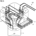
- Fig. 5 illustrates a foundation for an electrical power engineering structure according to an embodiment of the present invention.
- the foundation 150 which in Fig. 5 is illustrated in a perspective view, a connection structure 100 according to an embodiment of the present invention (as shown in FIG Figs. 1 to 4 is illustrated) and a seabed anchor 111, which is anchored in a seabed 153.
- the seabed anchor 111 is in the in Fig. 5
- the illustrated embodiment is designed as a hollow driven pile which is rammed into the sea bed 153 and has a circular cross-sectional shape, the diameter d of which is smaller as a side length 1 of the cross section of the spatial region 105 or the circumferential wall 101.
- the seabed anchor 101 is connected at an upper end to the lower connecting section 109 of the connecting structure 100, for example by means of grouting mortar, welding, screws, etc.
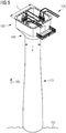
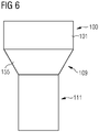
- the connecting structure 100 has a shape transition 155 (see FIG Fig. 6 ) a cross-sectional shape of the space region 105 or the wall 101 to a cross-sectional shape of an upper end of the seabed anchorage 111.
- the shape transition 155 runs essentially from square to circular, as in FIG Figs. 5 and 6th can be seen.
- Fig. 5 Illustrates in a schematic perspective representation a foundation 150 according to an embodiment of the present invention, which has a single connection structure 100 according to an embodiment of the present invention, as well as a single seabed anchor 111. According to other embodiments, a foundation comprises four seabed anchors each with connected connection structures 100.
- Fig. 7 illustrates in a schematic perspective representation a marine installation 160 according to an embodiment of the present invention, which has a structure 157 for power engineering and a foundation 250, which is for example formed by four foundations 150 as shown in FIG Fig. 5 illustrated is formed.
- the structure 157 is on the flanges 117 (see Fig. 2 ) of the respective connection structures 100 attached.
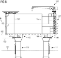
- Fig. 8 illustrates in a schematic side view or side sectional view the installation 160 which is shown in FIG Fig. 7 is illustrated in a perspective view.
- the structure 157 comprises a load-bearing wall 163 (or 164) which vertically (ie in the vertical direction 103) is essentially in line with a section 165 (or 164). 166) of the vertical wall 101 of the connecting structure 100 is arranged. An improved support of the structure 157 is thus achieved.
- a cable deck level 180 is below a lowest level 182 of the structure 157.
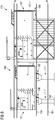
- Fig. 9 shows a schematic side view of a marine installation 160 in comparison to a conventional marine installation 170.
- the line 161 illustrates a lowest tidal range and a line 159 illustrates a 100-year wave level. How out Fig. 9 As can be seen, the connection structure 100 is arranged substantially below the 100-year wave level 159, but substantially above the lowest tidal range level 161.
- the conventional marine installation comprises, in the conventional structure 167, a lower deck 169 which is used for connecting and pulling up cables.
- connection deck 169 of the structure can be saved, whereby a total height h1 of the marine installation 160 according to an embodiment of the present invention can be achieved, which total height h1 is less (for example by 3 to 6 m) than a total height h2 of the conventional marine installation 170.
- the heights h1, h2 are each measured in relation to the lowest tidal level 161.
- connection structure 100 is guided along the walls in order to ensure sufficient space for the connection within the spatial area of the connection structure 100.
- the foundation piles shown here can serve as a cable guide for up to 16 AC cables (33kV, 66kV) and two DC cables.
- the fourth foundation pile can be specifically designed to accommodate the cooling water pumps of an HVDC system.
- an open sea cooling water system can be implemented.
- the submersible pumps had to be pulled out of the water and dismantled into several parts, which was time-consuming, in order to reach the actual pump head at the inlet of the riser pipe.
- connection structure 100 can also be viewed as an expansion of the cylindrical structure to a square structure.
- This expansion can have several advantages: on the one hand, the flow of force and the introduction of force from the structure into the connection structure can be optimized. This can lead to reduced deflection and material savings in the area of the raised floor of the structure.
- cable pulling and cable connections can be carried out in a closed room (the room area 105) and are therefore independent of external weather influences.
- An additional cable deck for the construction can thus be superfluous. This can save volume inside or below the structure.
- the space area can be used as a cable connection space and can be in the area of the zone of influence of a century wave. This can lead to a possible reduction in the height of the structure.
- the dimensions of the expansion of the connection structure and the upper flange can enable an optimal flow of forces in the transverse and longitudinal walls of the raised floor of the structure, despite installation tolerances.
- the dimensions of the connecting structure can be chosen so that the (load-bearing) walls of the structure are an extension of the main walls or the load-bearing walls of the structure.
- connection between the connection structure and the structure should be designed as a screw connection via an internal or external flange.
- a form-fitting connection can be made using grouting mortar or equivalent.
- the combination of four foundation piles can be used as a foundation for a superstructure of approximately 10,000 tons. Up to 16 AC cables plus two DC cables can be routed inside three of the four foundation piles.
- the fourth foundation pile can provide enough space to accommodate the pipes and pumps for the cooling water circuit.
- the upper part of the connection structures can preferably be designed in such a way that it serves to position directly adjacent connection structures on the foundation piles before the grouting process.
- the cable coming from the clusters of the wind farm can vertically up to below the foundation piles via deflection pulleys Ceiling of the transition structure to be drawn.
- the tensile force can be exerted on the cable by means of a temporarily installed cable winch located outside the interior area via pulleys.
- the cable hang-off can be carried out directly below the connection structure, in the parallel part of the foundation pile on an intermediate deck.
- the outer sheathing of the cables is removed and the steel reinforcement is fixed by means of a flange in order to provide strain relief for the submarine cables.
- a circular opening e.g. 123 shown in FIG Fig. 1 ) intended.
- the cables are lowered again, run on the intermediate deck (hang-off deck) in the outer diameter of the deck and the entire outer insulation is removed. From there, the individual wires of the cables are guided along the conical wall of the connection structure and guided vertically through openings in the cable deck in the transition or connection structure. There the cables can be connected to the platform internals and passed through the platform.
- Pipes and pumps of a cooling water circuit can be installed inside a foundation pile.
- the suction pumps previously used could be replaced by centrifugal pumps.
- the pumps arranged above the water level can therefore be easily serviced through access in the room area.
- a steel cable routing in the form of a J-tube can be dispensed with according to the state of the art, with the exception of the two export cables, and. a flexible cable duct with flexible cable protection can be used.
- a foundation structure with one or more, e.g. three suction buckets can be used instead of a driven pile 111.
- This can result in further advantages, such as Avoidance of the ramming process during installation, no underwater grouting operation offshore, reduction of crane ship lifting capacity compared to a jacket installation or even abandonment of crane ship operations for foundation installation, offshore through self-floating transport.
- Another advantage of this design is that the complete system can be equipped with all add-on parts without the components being exposed to the high acceleration forces and fatigue during the pile-driving process.
- the connection structure can be extended downwards according to the water depth and the installation location and at the lower end it can be disembarked as a complete unit as a foundation structure with the suction cans.
Landscapes
- Engineering & Computer Science (AREA)
- General Engineering & Computer Science (AREA)
- Civil Engineering (AREA)
- Structural Engineering (AREA)
- Mechanical Engineering (AREA)
- Life Sciences & Earth Sciences (AREA)
- Paleontology (AREA)
- Mining & Mineral Resources (AREA)
- General Life Sciences & Earth Sciences (AREA)
- Architecture (AREA)
- Sustainable Development (AREA)
- Sustainable Energy (AREA)
- Chemical & Material Sciences (AREA)
- Combustion & Propulsion (AREA)
- Laying Of Electric Cables Or Lines Outside (AREA)
- Foundations (AREA)
Priority Applications (4)
| Application Number | Priority Date | Filing Date | Title |
|---|---|---|---|
| PL18157798T PL3530809T3 (pl) | 2018-02-21 | 2018-02-21 | Struktura łącząca do instalacji morskiej |
| EP18157798.2A EP3530809B1 (de) | 2018-02-21 | 2018-02-21 | Verbindungsstruktur für eine meeresinstallation |
| DK18157798.2T DK3530809T3 (da) | 2018-02-21 | 2018-02-21 | Forbindelsesstruktur til en havinstallation |
| US16/281,340 US10738431B2 (en) | 2018-02-21 | 2019-02-21 | Connection structure for a marine installation, marine installation and method of erecting a marine installation |
Applications Claiming Priority (1)
| Application Number | Priority Date | Filing Date | Title |
|---|---|---|---|
| EP18157798.2A EP3530809B1 (de) | 2018-02-21 | 2018-02-21 | Verbindungsstruktur für eine meeresinstallation |
Publications (2)
| Publication Number | Publication Date |
|---|---|
| EP3530809A1 EP3530809A1 (de) | 2019-08-28 |
| EP3530809B1 true EP3530809B1 (de) | 2020-12-16 |
Family
ID=61256649
Family Applications (1)
| Application Number | Title | Priority Date | Filing Date |
|---|---|---|---|
| EP18157798.2A Active EP3530809B1 (de) | 2018-02-21 | 2018-02-21 | Verbindungsstruktur für eine meeresinstallation |
Country Status (4)
| Country | Link |
|---|---|
| US (1) | US10738431B2 (pl) |
| EP (1) | EP3530809B1 (pl) |
| DK (1) | DK3530809T3 (pl) |
| PL (1) | PL3530809T3 (pl) |
Families Citing this family (5)
| Publication number | Priority date | Publication date | Assignee | Title |
|---|---|---|---|---|
| US10767632B2 (en) * | 2016-09-09 | 2020-09-08 | Siemens Gamesa Renewable Energy A/S | Transition piece for a wind turbine |
| DK3875754T3 (en) * | 2020-03-03 | 2025-11-10 | Siemens Gamesa Renewable Energy As | Wind turbine |
| EP4150726A4 (en) * | 2020-05-13 | 2024-06-19 | Gaf Energy LLC | Electrical cable passthrough |
| EP4141257A1 (en) * | 2021-08-24 | 2023-03-01 | Siemens Gamesa Renewable Energy A/S | Wind turbine with direct grid connection |
| CN117895411B (zh) * | 2023-11-28 | 2026-02-17 | 广东中远海运重工有限公司 | 海缆贯穿结构 |
Citations (1)
| Publication number | Priority date | Publication date | Assignee | Title |
|---|---|---|---|---|
| WO2015019664A1 (ja) * | 2013-08-06 | 2015-02-12 | 株式会社日立産機システム | 風力発電システム及びその変圧器搬入、搬出方法 |
Family Cites Families (19)
| Publication number | Priority date | Publication date | Assignee | Title |
|---|---|---|---|---|
| US3916632A (en) * | 1974-05-06 | 1975-11-04 | Interseas Associates | Telescopic caisson with intermediately positioned wellhead |
| JPS57500521A (pl) * | 1980-05-02 | 1982-03-25 | ||
| NO850517L (no) * | 1985-02-12 | 1986-08-13 | Saga Petroleum | Konstruksjonsgeometri og -form for offshore betongplattform. |
| NO850836L (no) * | 1985-03-01 | 1986-09-02 | Norske Stats Oljeselskap | System for utvikling og utbygging av olje- og/eller gassfelter til havs. |
| US6371695B1 (en) * | 1998-11-06 | 2002-04-16 | Exxonmobil Upstream Research Company | Offshore caisson having upper and lower sections separated by a structural diaphragm and method of installing the same |
| ATE441030T1 (de) * | 2002-03-08 | 2009-09-15 | Ocean Wind Energy Systems | Offshore-windenergieanlage |
| ITTO20070666A1 (it) * | 2007-09-24 | 2009-03-25 | Blue H Intellectual Properties | Sistema di conversione di energia eolica offshore per acque profonde |
| US8613569B2 (en) * | 2008-11-19 | 2013-12-24 | Efficient Engineering, Llc | Stationary positioned offshore windpower plant (OWP) and the methods and means for its assembling, transportation, installation and servicing |
| EP2406491A1 (en) * | 2009-03-13 | 2012-01-18 | XEMC Darwind B.V. | Method of constructing a wind turbine and bottom tower section of wind turbine |
| GB2473058A (en) * | 2009-08-29 | 2011-03-02 | Slp Engineering Ltd | Transition piece with conduit located around the pile of an offshore installation |
| US8240955B2 (en) * | 2010-06-29 | 2012-08-14 | General Electric Company | Tower segments and method for off-shore wind turbines |
| US8573891B2 (en) * | 2010-10-04 | 2013-11-05 | Horton Wison Deepwater, Inc. | Tension buoyant tower |
| FR2966175B1 (fr) * | 2010-10-18 | 2012-12-21 | Doris Engineering | Dispositif de support d'une eolienne de production d'energie electrique en mer, installation de production d'energie electrique en mer correspondante. |
| EP2691650B1 (en) * | 2011-03-30 | 2018-05-16 | Vestas Wind Systems A/S | Methods and apparatus for servicing wind turbine components through a lower portion of a tower |
| US20120049532A1 (en) * | 2011-08-23 | 2012-03-01 | Scholte-Wassink Hartmut Andreas | Wind turbine |
| ES2415058B2 (es) * | 2011-10-18 | 2015-10-06 | Esteyco Energía S.L. | Mejoras en el procedimiento de instalación de torre para uso aguas adentro. |
| FR2983225B1 (fr) * | 2011-11-25 | 2013-12-20 | Stx France Sa | Piece de transition pour une structure de fondation |
| US9599254B2 (en) * | 2013-01-22 | 2017-03-21 | Seatower As | Apparatus and method for installation and protection of sub sea cables |
| KR20150145978A (ko) * | 2014-06-20 | 2015-12-31 | 삼성중공업 주식회사 | 해상 풍력발전기의 박스형 하부 구조물 |
-
2018
- 2018-02-21 DK DK18157798.2T patent/DK3530809T3/da active
- 2018-02-21 EP EP18157798.2A patent/EP3530809B1/de active Active
- 2018-02-21 PL PL18157798T patent/PL3530809T3/pl unknown
-
2019
- 2019-02-21 US US16/281,340 patent/US10738431B2/en active Active
Patent Citations (1)
| Publication number | Priority date | Publication date | Assignee | Title |
|---|---|---|---|---|
| WO2015019664A1 (ja) * | 2013-08-06 | 2015-02-12 | 株式会社日立産機システム | 風力発電システム及びその変圧器搬入、搬出方法 |
Also Published As
| Publication number | Publication date |
|---|---|
| US20190257051A1 (en) | 2019-08-22 |
| DK3530809T3 (da) | 2021-02-22 |
| PL3530809T3 (pl) | 2021-08-02 |
| EP3530809A1 (de) | 2019-08-28 |
| US10738431B2 (en) | 2020-08-11 |
Similar Documents
| Publication | Publication Date | Title |
|---|---|---|
| EP3530809B1 (de) | Verbindungsstruktur für eine meeresinstallation | |
| EP2909476B1 (de) | Versorgungsgerüst für einen turm, turm mit einem versorgungsgerüst sowie verfahren zum errichten eines versorgungsgerüsts im inneren eines turms | |
| EP1288122B1 (de) | Schwimmfundament für ein über die Wasseroberfläche aufragendes Bauwerk | |
| EP1145397B1 (de) | Verfahren zum verlegen von elektrischen kabeln von einer ersten offshore-windenergieanlage zu einer zweiten offshore-windenergieanlage | |
| EP2229313B1 (de) | Schwimmendes gründungstragwerk mit auftriebskomponenten, in aufgelöster bauweise | |
| DE102011052024A1 (de) | Serienbaufähiges schwimmfundament | |
| DE10349109A1 (de) | Gründung für eine Offshore-Windenergieanlage | |
| DE102012003572A1 (de) | Offshore-Plattform-Konstruktion sowie Verfahren zur Errichtung einer Offshore-Windturbinenstation | |
| EP1985845A1 (de) | Gründung für eine Offshore-Windenergieanlage mit mindestens einer Seekabeldurchführung | |
| DE102008028476A1 (de) | Offshore-Umspannwerk mit Kabelbogen | |
| WO2022089915A2 (de) | Windkraftanlagengründungsstruktur | |
| EP2796620B1 (de) | Verfahren zur Herstellung eines Gründungspfahls für Offshore-Bauwerke sowie Gründungspfahl für Offshore-Bauwerke | |
| EP3064648B1 (de) | Bootsanleger für eine offshore-anlage, offshore-anlage mit einem solchen bootsanleger und verfahren zum montieren des bootsanlegers | |
| EP4237625A1 (de) | Offshore-windenergiesystem | |
| DE102012008120A1 (de) | Verfahren zum Errichten eines Turmeinbaus in einem Windenergieanlagenturm | |
| DE102010015761A1 (de) | Standstruktur | |
| EP2725223B1 (de) | Windkraftanlagengruppe | |
| EP2586917A2 (de) | Offshore-Plattform-Konstruktion | |
| DE102011109251A1 (de) | Katamaran-Ponton | |
| EP3597829A1 (de) | Gründungsverstärkung für offshore-bauwerke | |
| EP3530814A1 (de) | Verfahren zur gründung einer umspannplattform und umspannfplattform mit wenigstens vier pfählen | |
| EP2351885A1 (de) | Offshore-Bauwerk | |
| WO2023285068A1 (de) | Gründungstruktur eines offshore-bauwerks | |
| EP3950487B1 (de) | Ankersystem zum verankern eines offshore-bauwerks | |
| EP4621132A1 (de) | Eine auf mehreren miteinander verbundenen einzel-grundpfählen gegründete plattform |
Legal Events
| Date | Code | Title | Description |
|---|---|---|---|
| PUAI | Public reference made under article 153(3) epc to a published international application that has entered the european phase |
Free format text: ORIGINAL CODE: 0009012 |
|
| STAA | Information on the status of an ep patent application or granted ep patent |
Free format text: STATUS: THE APPLICATION HAS BEEN PUBLISHED |
|
| AK | Designated contracting states |
Kind code of ref document: A1 Designated state(s): AL AT BE BG CH CY CZ DE DK EE ES FI FR GB GR HR HU IE IS IT LI LT LU LV MC MK MT NL NO PL PT RO RS SE SI SK SM TR |
|
| AX | Request for extension of the european patent |
Extension state: BA ME |
|
| STAA | Information on the status of an ep patent application or granted ep patent |
Free format text: STATUS: REQUEST FOR EXAMINATION WAS MADE |
|
| 17P | Request for examination filed |
Effective date: 20190919 |
|
| RBV | Designated contracting states (corrected) |
Designated state(s): AL AT BE BG CH CY CZ DE DK EE ES FI FR GB GR HR HU IE IS IT LI LT LU LV MC MK MT NL NO PL PT RO RS SE SI SK SM TR |
|
| STAA | Information on the status of an ep patent application or granted ep patent |
Free format text: STATUS: EXAMINATION IS IN PROGRESS |
|
| 17Q | First examination report despatched |
Effective date: 20200304 |
|
| GRAP | Despatch of communication of intention to grant a patent |
Free format text: ORIGINAL CODE: EPIDOSNIGR1 |
|
| STAA | Information on the status of an ep patent application or granted ep patent |
Free format text: STATUS: GRANT OF PATENT IS INTENDED |
|
| INTG | Intention to grant announced |
Effective date: 20200730 |
|
| GRAS | Grant fee paid |
Free format text: ORIGINAL CODE: EPIDOSNIGR3 |
|
| GRAA | (expected) grant |
Free format text: ORIGINAL CODE: 0009210 |
|
| STAA | Information on the status of an ep patent application or granted ep patent |
Free format text: STATUS: THE PATENT HAS BEEN GRANTED |
|
| AK | Designated contracting states |
Kind code of ref document: B1 Designated state(s): AL AT BE BG CH CY CZ DE DK EE ES FI FR GB GR HR HU IE IS IT LI LT LU LV MC MK MT NL NO PL PT RO RS SE SI SK SM TR |
|
| REG | Reference to a national code |
Ref country code: GB Ref legal event code: FG4D Free format text: NOT ENGLISH |
|
| REG | Reference to a national code |
Ref country code: DE Ref legal event code: R096 Ref document number: 502018003288 Country of ref document: DE |
|
| REG | Reference to a national code |
Ref country code: IE Ref legal event code: FG4D Free format text: LANGUAGE OF EP DOCUMENT: GERMAN |
|
| REG | Reference to a national code |
Ref country code: AT Ref legal event code: REF Ref document number: 1345720 Country of ref document: AT Kind code of ref document: T Effective date: 20210115 |
|
| RAP2 | Party data changed (patent owner data changed or rights of a patent transferred) |
Owner name: SIEMENS ENERGY GLOBAL GMBH & CO. KG |
|
| REG | Reference to a national code |
Ref country code: DK Ref legal event code: T3 Effective date: 20210217 |
|
| REG | Reference to a national code |
Ref country code: NL Ref legal event code: FP |
|
| PG25 | Lapsed in a contracting state [announced via postgrant information from national office to epo] |
Ref country code: FI Free format text: LAPSE BECAUSE OF FAILURE TO SUBMIT A TRANSLATION OF THE DESCRIPTION OR TO PAY THE FEE WITHIN THE PRESCRIBED TIME-LIMIT Effective date: 20201216 Ref country code: RS Free format text: LAPSE BECAUSE OF FAILURE TO SUBMIT A TRANSLATION OF THE DESCRIPTION OR TO PAY THE FEE WITHIN THE PRESCRIBED TIME-LIMIT Effective date: 20201216 Ref country code: NO Free format text: LAPSE BECAUSE OF FAILURE TO SUBMIT A TRANSLATION OF THE DESCRIPTION OR TO PAY THE FEE WITHIN THE PRESCRIBED TIME-LIMIT Effective date: 20210316 Ref country code: GR Free format text: LAPSE BECAUSE OF FAILURE TO SUBMIT A TRANSLATION OF THE DESCRIPTION OR TO PAY THE FEE WITHIN THE PRESCRIBED TIME-LIMIT Effective date: 20210317 |
|
| PG25 | Lapsed in a contracting state [announced via postgrant information from national office to epo] |
Ref country code: BG Free format text: LAPSE BECAUSE OF FAILURE TO SUBMIT A TRANSLATION OF THE DESCRIPTION OR TO PAY THE FEE WITHIN THE PRESCRIBED TIME-LIMIT Effective date: 20210316 Ref country code: LV Free format text: LAPSE BECAUSE OF FAILURE TO SUBMIT A TRANSLATION OF THE DESCRIPTION OR TO PAY THE FEE WITHIN THE PRESCRIBED TIME-LIMIT Effective date: 20201216 Ref country code: SE Free format text: LAPSE BECAUSE OF FAILURE TO SUBMIT A TRANSLATION OF THE DESCRIPTION OR TO PAY THE FEE WITHIN THE PRESCRIBED TIME-LIMIT Effective date: 20201216 |
|
| PG25 | Lapsed in a contracting state [announced via postgrant information from national office to epo] |
Ref country code: HR Free format text: LAPSE BECAUSE OF FAILURE TO SUBMIT A TRANSLATION OF THE DESCRIPTION OR TO PAY THE FEE WITHIN THE PRESCRIBED TIME-LIMIT Effective date: 20201216 |
|
| REG | Reference to a national code |
Ref country code: LT Ref legal event code: MG9D |
|
| PG25 | Lapsed in a contracting state [announced via postgrant information from national office to epo] |
Ref country code: CZ Free format text: LAPSE BECAUSE OF FAILURE TO SUBMIT A TRANSLATION OF THE DESCRIPTION OR TO PAY THE FEE WITHIN THE PRESCRIBED TIME-LIMIT Effective date: 20201216 Ref country code: EE Free format text: LAPSE BECAUSE OF FAILURE TO SUBMIT A TRANSLATION OF THE DESCRIPTION OR TO PAY THE FEE WITHIN THE PRESCRIBED TIME-LIMIT Effective date: 20201216 Ref country code: LT Free format text: LAPSE BECAUSE OF FAILURE TO SUBMIT A TRANSLATION OF THE DESCRIPTION OR TO PAY THE FEE WITHIN THE PRESCRIBED TIME-LIMIT Effective date: 20201216 Ref country code: SM Free format text: LAPSE BECAUSE OF FAILURE TO SUBMIT A TRANSLATION OF THE DESCRIPTION OR TO PAY THE FEE WITHIN THE PRESCRIBED TIME-LIMIT Effective date: 20201216 Ref country code: PT Free format text: LAPSE BECAUSE OF FAILURE TO SUBMIT A TRANSLATION OF THE DESCRIPTION OR TO PAY THE FEE WITHIN THE PRESCRIBED TIME-LIMIT Effective date: 20210416 Ref country code: RO Free format text: LAPSE BECAUSE OF FAILURE TO SUBMIT A TRANSLATION OF THE DESCRIPTION OR TO PAY THE FEE WITHIN THE PRESCRIBED TIME-LIMIT Effective date: 20201216 Ref country code: SK Free format text: LAPSE BECAUSE OF FAILURE TO SUBMIT A TRANSLATION OF THE DESCRIPTION OR TO PAY THE FEE WITHIN THE PRESCRIBED TIME-LIMIT Effective date: 20201216 |
|
| REG | Reference to a national code |
Ref country code: DE Ref legal event code: R097 Ref document number: 502018003288 Country of ref document: DE |
|
| PG25 | Lapsed in a contracting state [announced via postgrant information from national office to epo] |
Ref country code: MC Free format text: LAPSE BECAUSE OF FAILURE TO SUBMIT A TRANSLATION OF THE DESCRIPTION OR TO PAY THE FEE WITHIN THE PRESCRIBED TIME-LIMIT Effective date: 20201216 Ref country code: IS Free format text: LAPSE BECAUSE OF FAILURE TO SUBMIT A TRANSLATION OF THE DESCRIPTION OR TO PAY THE FEE WITHIN THE PRESCRIBED TIME-LIMIT Effective date: 20210416 |
|
| PLBE | No opposition filed within time limit |
Free format text: ORIGINAL CODE: 0009261 |
|
| STAA | Information on the status of an ep patent application or granted ep patent |
Free format text: STATUS: NO OPPOSITION FILED WITHIN TIME LIMIT |
|
| REG | Reference to a national code |
Ref country code: BE Ref legal event code: MM Effective date: 20210228 |
|
| PG25 | Lapsed in a contracting state [announced via postgrant information from national office to epo] |
Ref country code: CH Free format text: LAPSE BECAUSE OF NON-PAYMENT OF DUE FEES Effective date: 20210228 Ref country code: AL Free format text: LAPSE BECAUSE OF FAILURE TO SUBMIT A TRANSLATION OF THE DESCRIPTION OR TO PAY THE FEE WITHIN THE PRESCRIBED TIME-LIMIT Effective date: 20201216 Ref country code: LI Free format text: LAPSE BECAUSE OF NON-PAYMENT OF DUE FEES Effective date: 20210228 Ref country code: LU Free format text: LAPSE BECAUSE OF NON-PAYMENT OF DUE FEES Effective date: 20210221 Ref country code: IT Free format text: LAPSE BECAUSE OF FAILURE TO SUBMIT A TRANSLATION OF THE DESCRIPTION OR TO PAY THE FEE WITHIN THE PRESCRIBED TIME-LIMIT Effective date: 20201216 |
|
| 26N | No opposition filed |
Effective date: 20210917 |
|
| REG | Reference to a national code |
Ref country code: GB Ref legal event code: 732E Free format text: REGISTERED BETWEEN 20211202 AND 20211209 |
|
| PG25 | Lapsed in a contracting state [announced via postgrant information from national office to epo] |
Ref country code: ES Free format text: LAPSE BECAUSE OF FAILURE TO SUBMIT A TRANSLATION OF THE DESCRIPTION OR TO PAY THE FEE WITHIN THE PRESCRIBED TIME-LIMIT Effective date: 20201216 Ref country code: FR Free format text: LAPSE BECAUSE OF NON-PAYMENT OF DUE FEES Effective date: 20210228 Ref country code: IE Free format text: LAPSE BECAUSE OF NON-PAYMENT OF DUE FEES Effective date: 20210221 |
|
| PG25 | Lapsed in a contracting state [announced via postgrant information from national office to epo] |
Ref country code: SI Free format text: LAPSE BECAUSE OF FAILURE TO SUBMIT A TRANSLATION OF THE DESCRIPTION OR TO PAY THE FEE WITHIN THE PRESCRIBED TIME-LIMIT Effective date: 20201216 |
|
| PG25 | Lapsed in a contracting state [announced via postgrant information from national office to epo] |
Ref country code: BE Free format text: LAPSE BECAUSE OF NON-PAYMENT OF DUE FEES Effective date: 20210228 |
|
| PG25 | Lapsed in a contracting state [announced via postgrant information from national office to epo] |
Ref country code: CY Free format text: LAPSE BECAUSE OF FAILURE TO SUBMIT A TRANSLATION OF THE DESCRIPTION OR TO PAY THE FEE WITHIN THE PRESCRIBED TIME-LIMIT Effective date: 20201216 |
|
| PG25 | Lapsed in a contracting state [announced via postgrant information from national office to epo] |
Ref country code: HU Free format text: LAPSE BECAUSE OF FAILURE TO SUBMIT A TRANSLATION OF THE DESCRIPTION OR TO PAY THE FEE WITHIN THE PRESCRIBED TIME-LIMIT; INVALID AB INITIO Effective date: 20180221 |
|
| REG | Reference to a national code |
Ref country code: AT Ref legal event code: MM01 Ref document number: 1345720 Country of ref document: AT Kind code of ref document: T Effective date: 20230221 |
|
| PG25 | Lapsed in a contracting state [announced via postgrant information from national office to epo] |
Ref country code: AT Free format text: LAPSE BECAUSE OF NON-PAYMENT OF DUE FEES Effective date: 20230221 |
|
| PG25 | Lapsed in a contracting state [announced via postgrant information from national office to epo] |
Ref country code: MK Free format text: LAPSE BECAUSE OF FAILURE TO SUBMIT A TRANSLATION OF THE DESCRIPTION OR TO PAY THE FEE WITHIN THE PRESCRIBED TIME-LIMIT Effective date: 20201216 Ref country code: AT Free format text: LAPSE BECAUSE OF NON-PAYMENT OF DUE FEES Effective date: 20230221 |
|
| PG25 | Lapsed in a contracting state [announced via postgrant information from national office to epo] |
Ref country code: MT Free format text: LAPSE BECAUSE OF FAILURE TO SUBMIT A TRANSLATION OF THE DESCRIPTION OR TO PAY THE FEE WITHIN THE PRESCRIBED TIME-LIMIT Effective date: 20201216 |
|
| PGFP | Annual fee paid to national office [announced via postgrant information from national office to epo] |
Ref country code: DE Payment date: 20250226 Year of fee payment: 8 |
|
| PGFP | Annual fee paid to national office [announced via postgrant information from national office to epo] |
Ref country code: DK Payment date: 20250224 Year of fee payment: 8 |
|
| PGFP | Annual fee paid to national office [announced via postgrant information from national office to epo] |
Ref country code: PL Payment date: 20250205 Year of fee payment: 8 |
|
| PGFP | Annual fee paid to national office [announced via postgrant information from national office to epo] |
Ref country code: GB Payment date: 20250218 Year of fee payment: 8 |
|
| PG25 | Lapsed in a contracting state [announced via postgrant information from national office to epo] |
Ref country code: TR Free format text: LAPSE BECAUSE OF FAILURE TO SUBMIT A TRANSLATION OF THE DESCRIPTION OR TO PAY THE FEE WITHIN THE PRESCRIBED TIME-LIMIT Effective date: 20201216 |
|
| PGFP | Annual fee paid to national office [announced via postgrant information from national office to epo] |
Ref country code: NL Payment date: 20260220 Year of fee payment: 9 |