US3916632A - Telescopic caisson with intermediately positioned wellhead - Google Patents
Telescopic caisson with intermediately positioned wellhead Download PDFInfo
- Publication number
- US3916632A US3916632A US467236A US46723674A US3916632A US 3916632 A US3916632 A US 3916632A US 467236 A US467236 A US 467236A US 46723674 A US46723674 A US 46723674A US 3916632 A US3916632 A US 3916632A
- Authority
- US
- United States
- Prior art keywords
- caisson
- fixed
- telescopic
- wellhead
- telescoping
- Prior art date
- Legal status (The legal status is an assumption and is not a legal conclusion. Google has not performed a legal analysis and makes no representation as to the accuracy of the status listed.)
- Expired - Lifetime
Links
- XLYOFNOQVPJJNP-UHFFFAOYSA-N water Substances O XLYOFNOQVPJJNP-UHFFFAOYSA-N 0.000 claims abstract description 42
- 238000004519 manufacturing process Methods 0.000 claims description 21
- 238000012546 transfer Methods 0.000 claims description 18
- 241000282472 Canis lupus familiaris Species 0.000 claims description 14
- 238000007789 sealing Methods 0.000 claims description 11
- 238000005553 drilling Methods 0.000 claims description 7
- 238000000034 method Methods 0.000 claims description 6
- 238000009434 installation Methods 0.000 description 11
- 238000010276 construction Methods 0.000 description 5
- 239000000463 material Substances 0.000 description 5
- 239000004020 conductor Substances 0.000 description 4
- 239000007789 gas Substances 0.000 description 3
- 238000005452 bending Methods 0.000 description 2
- 230000015572 biosynthetic process Effects 0.000 description 2
- 239000002775 capsule Substances 0.000 description 2
- 230000002706 hydrostatic effect Effects 0.000 description 2
- 108010061309 E021 Proteins 0.000 description 1
- 230000003213 activating effect Effects 0.000 description 1
- 230000004075 alteration Effects 0.000 description 1
- 238000013459 approach Methods 0.000 description 1
- 239000003795 chemical substances by application Substances 0.000 description 1
- 238000004891 communication Methods 0.000 description 1
- 230000003750 conditioning effect Effects 0.000 description 1
- 238000011161 development Methods 0.000 description 1
- 238000009826 distribution Methods 0.000 description 1
- 230000009977 dual effect Effects 0.000 description 1
- 239000012530 fluid Substances 0.000 description 1
- 239000003112 inhibitor Substances 0.000 description 1
- 238000007689 inspection Methods 0.000 description 1
- 230000002452 interceptive effect Effects 0.000 description 1
- 230000007246 mechanism Effects 0.000 description 1
- 239000000203 mixture Substances 0.000 description 1
- 238000012544 monitoring process Methods 0.000 description 1
- 238000011017 operating method Methods 0.000 description 1
- 238000002360 preparation method Methods 0.000 description 1
- 238000003825 pressing Methods 0.000 description 1
- 239000003381 stabilizer Substances 0.000 description 1
- 238000003860 storage Methods 0.000 description 1
- 239000000126 substance Substances 0.000 description 1
Images


Classifications
-
- E—FIXED CONSTRUCTIONS
- E21—EARTH OR ROCK DRILLING; MINING
- E21B—EARTH OR ROCK DRILLING; OBTAINING OIL, GAS, WATER, SOLUBLE OR MELTABLE MATERIALS OR A SLURRY OF MINERALS FROM WELLS
- E21B7/00—Special methods or apparatus for drilling
- E21B7/12—Underwater drilling
- E21B7/136—Underwater drilling from non-buoyant support
-
- E—FIXED CONSTRUCTIONS
- E02—HYDRAULIC ENGINEERING; FOUNDATIONS; SOIL SHIFTING
- E02B—HYDRAULIC ENGINEERING
- E02B17/00—Artificial islands mounted on piles or like supports, e.g. platforms on raisable legs or offshore constructions; Construction methods therefor
- E02B17/02—Artificial islands mounted on piles or like supports, e.g. platforms on raisable legs or offshore constructions; Construction methods therefor placed by lowering the supporting construction to the bottom, e.g. with subsequent fixing thereto
- E02B17/021—Artificial islands mounted on piles or like supports, e.g. platforms on raisable legs or offshore constructions; Construction methods therefor placed by lowering the supporting construction to the bottom, e.g. with subsequent fixing thereto with relative movement between supporting construction and platform
-
- E—FIXED CONSTRUCTIONS
- E21—EARTH OR ROCK DRILLING; MINING
- E21B—EARTH OR ROCK DRILLING; OBTAINING OIL, GAS, WATER, SOLUBLE OR MELTABLE MATERIALS OR A SLURRY OF MINERALS FROM WELLS
- E21B33/00—Sealing or packing boreholes or wells
- E21B33/02—Surface sealing or packing
- E21B33/03—Well heads; Setting-up thereof
- E21B33/035—Well heads; Setting-up thereof specially adapted for underwater installations
- E21B33/037—Protective housings therefor
-
- E—FIXED CONSTRUCTIONS
- E21—EARTH OR ROCK DRILLING; MINING
- E21B—EARTH OR ROCK DRILLING; OBTAINING OIL, GAS, WATER, SOLUBLE OR MELTABLE MATERIALS OR A SLURRY OF MINERALS FROM WELLS
- E21B41/00—Equipment or details not covered by groups E21B15/00 - E21B40/00
- E21B41/08—Underwater guide bases, e.g. drilling templates; Levelling thereof
-
- E—FIXED CONSTRUCTIONS
- E21—EARTH OR ROCK DRILLING; MINING
- E21B—EARTH OR ROCK DRILLING; OBTAINING OIL, GAS, WATER, SOLUBLE OR MELTABLE MATERIALS OR A SLURRY OF MINERALS FROM WELLS
- E21B43/00—Methods or apparatus for obtaining oil, gas, water, soluble or meltable materials or a slurry of minerals from wells
- E21B43/01—Methods or apparatus for obtaining oil, gas, water, soluble or meltable materials or a slurry of minerals from wells specially adapted for obtaining from underwater installations
-
- E—FIXED CONSTRUCTIONS
- E02—HYDRAULIC ENGINEERING; FOUNDATIONS; SOIL SHIFTING
- E02B—HYDRAULIC ENGINEERING
- E02B17/00—Artificial islands mounted on piles or like supports, e.g. platforms on raisable legs or offshore constructions; Construction methods therefor
- E02B2017/0056—Platforms with supporting legs
-
- E—FIXED CONSTRUCTIONS
- E02—HYDRAULIC ENGINEERING; FOUNDATIONS; SOIL SHIFTING
- E02B—HYDRAULIC ENGINEERING
- E02B17/00—Artificial islands mounted on piles or like supports, e.g. platforms on raisable legs or offshore constructions; Construction methods therefor
- E02B2017/0095—Connections of subsea risers, piping or wiring with the offshore structure
Definitions
- telescoping caisson systems include US. Pat. No. 3,372,745, issued to B. G. Holmes, and U.S. Pat. No. 3,450,201, issued to K. A. Blenkam.
- a caisson assembly comprising a fixed lower section and an upper, telescopic section which fits over the lower section.
- the upper, telescopic section of Blenkam is necessarily larger in diameter than the lower section thereby causing the structure to be subjected to greater forces from waves thereby imparting more motion to the caisson.
- the smaller diameter of the lower, fixed section in Blenkam produces greater stresses at the mud line.
- Blenkam is further characterized by requiring that operations be conducted at atmospheric conditions, and the described operation of Blenkam requires that the wellhead be in a flooded state when the upper, telescopic caisson section is retracted, thereby limiting service on the system to the extended position of the telescoping caisson.
- the structure described therein is characterized by the use of the conductor pipe as the support for the upper telescopic section. This arrangement is undesirable since it does impart large bending loads and stresses to the conductor pipe especially when the caisson is in an extended position.
- the telescopic section is substantially larger in diameter than the conductor thereby exposing a much greater surface area to wind and wave forces.
- Holmes Because oof the general arrangement of the Holmes system as described, a subsea support structure is required to reduce bending of the conductor. The assembly and installation of such support structure presents basically all of the construction and fabrication problems which are associated with templates. Holmes also discloses that his system is operated under atmospheric conditions when the upper section is extended and the hatch opened to the atmosphere at the surface, there being no mention in Holmes of work operations on the wellhead when the telescoping section is retracted below the water surface.
- a principal object of the present invention is to provide a telescoping caisson comprising a fixed lower section embedded in the sea floor and a telescopic upper section which fits within the lower section and which can be'extended and retracted;
- the wellhead structure are housed within the lower caisson at a position intermediate the surface of the water and the sea floor, at a height to permit work operations on the wellhead when the telescopic section is retracted.
- the access to the wellheads can be achieved by lowering a transfer capsule to the upper surface of the telescoping section, after which a dry transfer can be effected for servicing the wellhead in the upper section of the fixed caisson.
- a further, important object of the invention is to provide'a telescoping caisson system in which the pressure inside the fixed and telescoping caissons can be either ambient or atmospheric.
- the upper end of the telescopic section is provided with a separate isolated transfer chamber in order to facilitate entry to the caisson.
- the maintaining of the system at ambient pressures permits access to the wellhead through the telescopic section when extended to be readily accomplished since no watertight seal is required between the two sections due to the increased internal pressure which prevents water from entering the caisson. lf ambient conditions are maintained, satisfactory mixtures of breathable gases can be maintained in the caisson. If
- suitable sealing means must be provided between the fixed and telescoping caissons in order to prevent the ingress of water into the system due to the hydrostatic pressure.
- a further object of the invention is to provide a caisson of the type described in which the construction is relatively simple and in which the installation can be easily effected.
- the fixed caisson can be jetted in the sea floor and grouted into position, preferably in accordance with the techniques disclosed and claimed in my earlier co-pending application Ser. No. 354,949 filed Apr. 27, 1973, entitled Production and Flare Caisson System, which is incorporated by reference herein.
- the lower and telescoping caissons can be towed to location due to their inherent buoyancy and low drag coefficient, and the lower caisson can be easily uprighted and lowered into position by controlled flooding of the structure.
- the telescoping caisson is thereafter operatively connected to the lower caisson, and production equipment installed as necessary.
- a further object of the present invention is to provide novel sealing and locking means for sealing and locking sitions.
- Hydraulic or pneumatic control systems are provided for actuating the seals and locks, and stop means are installed on the fixed and telescopic caisson for limiting the upward and downward movement of the caisson.
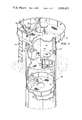
- FIG. 1 is a fragmentary perspective view of the telescoping caisson, with parts broken away to more clearly illustrate the interior construction thereof;
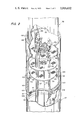
- FIG. 2 is a fragmentary perspective view illustrating the inner locking of the telescoping and fixed caissons, with sections of the caissons being broken away to expose the details of the locking arrangement and the interior of the caissons at the area of connection;
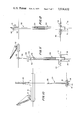
- FIG. 3 is a fragmentary perspective view showing the installation of the fixed caisson at the mud line
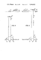
- FIG. 4 is a side elevational view showing the telescoping caisson in a retracted position
- FIG. 5 is a view similar to FIG. 4, showing the telescoping caisson in an extended position partially above the water line;
- FIGS. 612 are generally schematic figures showing the installation sequence of the fixed and telescoping caissons.
- FIGS. 6-12 a work vessl 10 having a crane 12 mounted thereon is located at the site and initially lowers a mudline template structure 14 to the mudline ML.
- FIG. 7 after positioning the template 14 at the mudline, supporting piles l6 and 18 are drilled into the sea floor through openings provided in the template, with the piles serving to rigidly support the fixed caisson.
- Conventional drilling equipment is employed, schematically illustrated at 20 in FIG. 7.
- the piles 16 after being installed are rigidly locked to the template and grouted so as to form a rigid assembly mounted at the mudline.
- a spud member 22 is similarly rigidly connected to the template 14 and forms a guide receptacle for the fixed caisson which is generally indicated at 24 in FIG. 10.
- the fixed caisson 24 can be lowered by the crane l2 and is rigidly locked to the template, with the lower end of the caisson extending into the spud member 22 and being grouted thereto.
- the piles I6 and 18 are essentially rigid support members rather than performing a dual function of supporting the caisson and permitting drilling and production through the supporting piles as disclosed in my earilier application.
- the drilling is effected through the fixed caisson 24 after the same has been installed in place, and before the telescoping caisson is operatively conne cted to the fixed caisson, as will be hereinafter described.
- FIG. 9 there is schematically illustrated therein the further step in the installation sequence comprising the drilling of the well through the fixed caisson 24 from the drilling equipment schematically shown at 20 on the deck of the vessel.
- a riser 26 is schematically shown extending through the fixed caisson, and the drill pipe extends through the riser in conventional manner for operation from the drilling equipment on the vessel.
- wellheads 28 are installed on the production casing and tubing 30, with the casing and tubing subsequent to the installation of the wellheads being removed above such point.
- the wellheads are positioned relative adjacent the top of the fixed caisson and intermediate the water level and sea floor to facilitate servicing of the wellheads when the telescoping caisson is either retracted or extended, as will be hereinafter explained in detail.
- the telescoping caisson illustrated generally at 32 in FIG. 11, is installed telescopically within the fixed caisson 24, with FIG. 11 showing the telescoping caisson 32 in a retracted position.
- the telescoping caisson 32 terminates at its upper end in a work deck 34, and an umbilicle line 36 extends upwardly therefrom, carrying at its upper end a buoy 38 which serves the usual function to visibly mark the location of the caisson assembly.
- the umbilicle line 36 carries the necessary equipment for operating the system, including electrical, hydraulic, air and water lines required to operate the system in the desired manner.
- the buoy 38 can be provided with radar reflectors, horns, lights, or the like to facilitate location of the same.
- the work platform 34 can have mounted thereon a sonar beacon (not shown) which can be used to transmit signals in the event the buoy 38 is lost, thereby permitting the location of the caisson assembly to be ascertained by equipment located in the area.
- a sonar beacon (not shown) which can be used to transmit signals in the event the buoy 38 is lost, thereby permitting the location of the caisson assembly to be ascertained by equipment located in the area.
- the various energy lines stored in the umbilicle line 36 can be operatively connected to sources of energy located on the work boat.
- FIG. 12 shows the telescoping caisson 32 in an extended position, with the work deck 34 extending above water level and supporting a crane 40 by means of which men, equipment and materials can be raised and lowered through the telescoping caisson section to the wellheads.
- a transfer chamber 42 is located between the platform 34 and the telescoping caisson itself for providing the desired environment for transferring the men from the deck when exposed to the interior of the telescoping caisson, which may be in accordance with the invention at substantially different pressures.
- the present invention can advantageously operate with the interior of the telescoping caisson at ambient pressures in order to alleviate sealing problems and permitting a substantial reduction in the materials employed in the caisson walls.
- the transfer chamber 42 is necessary in order to maintain such pressure within the telescoping chamber when men and materials are admitted thereto.
- the operating sequence to raise and lower the telescoping caisson 32 will be hereinafter described in detail.
- the production line 44 is shown operatively connected to the production caisson just below the wellheads 28, and a flow line 46is operatively connected to the production line for conveying the oil to a suitable storage or handling facility, the details of which are not essential nor do they form part of the present invention.
- a second production control line 47 is also provided for alternatively providing control from a central station.
- the telescoping caisson 32 is illustrated therein, with the caisson being partially broken away to expose the interior construction thereof.
- the work deck 34 has mounted thereon a winch 50 by means of which a work line 52 can be lowered through the hatch 54 for lowering equipment and materials downwardly through the telescoping caisson.
- the umbilicle line 36 extends upwardly from the work deck as does chain 56 for the buoy 38.
- a guard rail 58 extends upwardly from the floor of the work deck for safety reasons.
- a second deck 60 is mounted within the telescoping caisson and serves as a transfer chamber 42 so that ambient pressure conditions can be achieved prior to entry of the servicemen into the interior of the telescoping caisson below the deck 60.
- a sealing hatch 62 is provided for closing the top hatch 54
- a sealing hatch 64 is provided for closing hatchway 66 formed in the deck 60 through which men and materials may enter the telescoping caisson below such deck.
- both sealing hatches are closed and the pressure within the transfer chamber elevated to the desired pressure through pressure lines provided in the umbilicle line 36, with the sealing hatch 64 thereafter being opened to permit entry into the lower portions of the telescoping caisson which are at the same pressure.
- Any additional supporting equipment can be mounted on the deck 60, for example, a control console 68 for monitoring and controlling operating conditions within the telescoping caisson.
- a ladder 69 extends downwardly from the work deck for gaining access thereto from the work boat.
- An elevator platform 70 is mounted within the telescoping caisson for perfomiing further operations within the caisson.
- An additional winch unit 72 is mounted on the platform 70 for raising and lowering the platform to the wellhead area, with the winch being operatively connected to a cable and clutch (not shown) for guiding and controlling the movement of the elevator.
- a ladder 74 extends vertically along the inside wall of the telescoping caisson and provides alternative access to the wellhead area. The latter also serves to stabilize and guide the platform 70, which is formed with a slot 75 for accommodating the ladder.
- a stop ring 79 is installed on the interior of the caisson 32 for limiting downward movement of the elevator 70.
- a walkway 76 and a further ladder 78 provide communication to and from the hatch 66 and the ladder 74.
- hatch opening 77 is formed centrally in the elevator platform 70.
- FIG. 2 this fragmentary perspective view is taken through the region of interlock of the fixed and telescoping caisson sections 24 and 32, respectively, and it will be noted that the telescoping caisson is of smaller diameter and fits within the fixed caisson 24.
- two wellheads are illustrated, generally designated at 80 and 82, although it will be understood that only one wellhead or more than two wellheads could be provided as well in accordance with the invention.
- Production casing commonly desig? nated at 84 operatively connect the wellheads to the oil formation through suitable valving well known to those in the art, and the outflow from the wellheads is delivered to production lines 44 for delivery to flow line.
- the wellhead structure and related equipment are of the type normally employed in surface production facilities and can be employed without significant alteration as contrasted, for example, with mudline completion system that require rather sophisticated structures.
- Work decks 86, 88 and 90 are provided rigidly secured to the production casing 84 to permit servicing of the equipment at several levels, with a ladder 92 permitting movement between such levels.
- the telescoping caisson is locked and sealed with respect to the fixed caisson at both its extended and retracted positions.
- the fixed caisson 24 has mounted thereon inflatable o-rings and .102 and a locking member 104 having a channel 106 formed therein. These members are secured to the inside wall of the fixed caisson 24, with the o-rings being operatively connected to hydraulic or pneumatic control lines for supplying fluid to inflate the same and thus seal the connection between the fixed and telescoping caissons.
- a locking ring 110 is mounted on the telescoping caisson 32 and carries a plurality of locking dogs 112 which are adapted to extend into the channel 106 formed in the locking member 104.
- the locking dogs 112 are likewise pneumatically or hydraulically actuated through suitable control lines, with the locking dogs in a non-actuating position not interfering with the movement of the telescoping caisson relative to the fixed caisson.
- the locking dogs 112 When the telescoping caisson has been properly vertically aligned following raising or lowering thereof, the locking dogs 112 are actuated for engagement in the channel 106 to secure the respective caisson numbers in "their vertically adjusted positions.
- Openings 114 are formed in the walls of the telescoping caisson 32 to permit actuation of the locking members 112 for entry into the locking channel 106.
- FIG. 3 there is shown therein in some what greater detail the construction of the mudline template 14 in the manner in which the fixed caisson is rigidly secured therein.
- the template 14 is mounted at the mudline and the piles 16 and 18 extend from the template near the periphery thereof through the sea floor as above described. Extending downwardly through an opening formed therefor in the template is the spud member 22 which extends substantially below the surface. Ribs commonly designated at 120 are rigidly connected to the top surface of the template and the spud member for rigidifying the assembly. Both the piles 16 and 18 and the spud member 22 are grouted in place after installation, with the grouting for the spud member being shown at 122. The template 14 is therefore rigidly installed on the sea floor.
- annular support member 122 can be provided outwardly of the spud member 22 for further rigidifying the latter and thus the entire support structure.
- the fixed caisson 24 extends downwardly within the spud member 22 and can also be grouted in following installation thereof to permanently secure the mounting thereof.
- a concrete plug 123 embeds the casings 84 and defines with the wall of the fixed caisson 24 a sump area, with sump line 124 being provided for draining the sump area by means of pump 125.
- a ladder 125 is provided for access to the mudline area.
- FIGS. 4 and 5 there is illustrated therein the telescoping caisson in its retracted and extended positions, respectively.
- the buoy 38 When retracted as shown in FIG. 4, the buoy 38 is visible at the surface and a work boat can readily identify the location of the caisson assembly.
- the umbilicle line 36 is hooked up to the energy sources and controls therefor on the work boat 10 and the telescoping caisson raised to its extended position shown in FIG. 5.
- men and equipment can be lowered through the hatchways of the telescoping caisson as previously described for access to the wellheads for performing the necessary surface operations.
- Suitable stabilizer and guide means are preferably provided for guiding the vertical movement of the telescoping caisson during extension and retraction thereof relative to the fixed caisson.
- a stop flange 130 is installed on the inner surface of the fixed caisson at the top thereof after the telescopic section has been set in place.
- the flange 130 limits the vertical upward movement of telescoping section 32 since it is positioned in the plane of the locking ring 140.
- Flange 130 is preferably formed with openings 132 through which water or air can pass to the annulus between the caissons to facilitate telescopic operations.
- an upper stop ring 134 is installed on the telescoping caisson 32 just below the work deck, with the ring 134 engaging the top annular surface of the fixed caisson to limit the descending movement of the telescoping caisson when retracted.
- the seals 100, 102 are inflated by applying pressure thereto thereby water sealing the connection between the fixed caisson and the telescoping caisson. Water or air is thereafter directed into the caisson from equipment stored on the work boat. Air is preferably used so that the wellheads can be maintained entirely dry regardless of whether the caisson is retracted or extended.
- the water within the telescopic caisson below the wellheads is forced through the annulus between the caissons and through the openings 132 in the stop flange 130.
- the locking dogs are re leased and when positive buoyancy has been achieved, the caisson 32 ascends, with the stop flange 130 limiting such ascent.
- the locking dogs 112 When caisson 32 is in the extended position, the locking dogs 112 are actuated to extend into the locking grooves 106 in the locking ring 104 at the upper level thereby locking the telescoping caisson to the fixed caisson.
- the seals and 102 are thereafter deflated by releasing the pneumatic or hydraulic pressure in the lines extending to said seals.
- air is supplied to the telescoping caisson to displace the water at least to the level of the wellheads, only if water flooding has been used to raise the caisson, with the seals being thereafter inflated.
- the air pressure is thereafter released through suitable valving mechanisms, preferably down to ambient pressures existing at the depth of the wellhead.
- suitable valving mechanisms preferably down to ambient pressures existing at the depth of the wellhead.
- the present invention is capable of operation either at ambient or atmospheric pressures, although ambient pressures are preferred for the reasons indicated.
- the hatch 62 is opened to permit access to the transfer section 42 after which preliminary inspection is made of the telescopic section before opening the lower hatch 64. Opening of the hatch 64 permits access to the interior of the telescopic caisson and the wellheads for servicing the same.
- the men and equipment are withdrawn from the telescoping section and preparations made to leave the transverse section 42.
- the hatch 64 is then closed and the seals 100 and 102 are deflated and the locking dogs 112 released thereby conditioning the caisson for descent.
- the air within the telescopic caisson is then released thereby permitting the caisson due to the weight thereof to descend, thereby keeping the wellhead dry since the pressure at the wellhead is always at ambient or above.
- the air is released from the caisson around the deflated seals in a controlled manner to avoid abrupt dropping of the telescopic section within the fixed section before descent.
- the stop ring 134 limits downward movement of the caisson. Air at ambient pressure or above always remains in the top portion of the caisson 32 thereby maintaining the wellheads in a dry condition.
- Atmospheric conditions within the telescoping caisson can be achieved by activating the seal between the two caissons in order to prevent water from entering the caisson due to the hydrostatic pressure at the area of interlock of the caissons beneath the water surface.
- the advantages of the present invention should be readily apparent from the foregoing description.
- the telescopic section is normally in the retracted position and the wave forces on the structure are thereby greatly reduced. Since the telescopic caisson is normally retracted, both caisson sections can be formed with thinner walls thereby substantially reducing fabricating costs.
- the diameter of the telescoping caisson is considerably less than the diameter of the fixed caisson thereby still further reducing the way forces on the caisson when in an extended position.
- the distribution of forces imparted to the overall structure can be further enhanced by designing the lower caisson with a larger diameter at the base then at its upper section thereby reducing the diameter of the caisson to compensate for the greater wave forces as you approach the water surface.
- helical spoilers can be formed on the upper section of the telescopic section in order to reduce dynamic forces resulting from waves, wind and current when the caisson is exposed above the water surface. As well known to those in the art, helical spoilers aid in changing the period and characteristics of vortex shedding whether caused by wind, waves or current.
- the present invention has the further advantage of tures are closed, and the caissons can be easily uprights and lowered into position by controlled flooding techniques.
- TFL wellheads can also be installed for servicing by pump down tools.
- the raising of the caisson can be accomplished by either releasing compressed gas from tanks stored within the caisson or by supplying gas from compressors on the surface support vessel via the umbilical line.
- the telescoping section can be raised mechanically by a suitably size crane on the support vessel.
- Apparatus for offshore oil production comprising:
- e. means for maintaining ambient pressure in said telescoping caisson when the same is in its extended and retracted position.
- said telescopic caisson includes a transfer section at the top thereof, and hatch means for separating said transfer section from the area of said telescopic caisson below said hatch means to facilitate transfer of service personnel from the surface to the exterior of said telescopic caisson.
- said locking means comprises a plurality of locking dogs carried by said telescopic caisson, and a locking ring carried by said fixed caisson, said locking ring being formed with a channel for receiving said locking dogs, and means for actuating said locking dogs for engagement in said channel for locking said telescopic caisson to said fixed caisson.
- the apparatus of claim 1 further including inflatable seal means in the annulus between said fixed and telescopic caissons, and means for inflating said seal means for water sealing the annulus between said caissons.
- said fixed caisson is permanently mounted on the sea floor by means of a mudline template, pipe means extending through said template and firmly embedded in the sea floor, and a spud member extending centrally through said template and receiving the lower end of said telescopic caisson, and means for rigidly connecting said fixed caisson to said spud member.
- the apparatus of claim 1 further including stop means carried respectively by said fixed and telescopic caissons for limiting the vertical upward and downward movement of said telescoping caisson relative to said fixed caisson.
- the apparatus of claim 1 further including an elevator platform within said telescopic caisson for vertical movement down to the wellhead area.
- Apparatus for offshore oil production comprising:
Landscapes
- Engineering & Computer Science (AREA)
- Geology (AREA)
- Life Sciences & Earth Sciences (AREA)
- Mining & Mineral Resources (AREA)
- Environmental & Geological Engineering (AREA)
- Fluid Mechanics (AREA)
- Physics & Mathematics (AREA)
- General Life Sciences & Earth Sciences (AREA)
- Geochemistry & Mineralogy (AREA)
- General Engineering & Computer Science (AREA)
- Mechanical Engineering (AREA)
- Civil Engineering (AREA)
- Structural Engineering (AREA)
- Earth Drilling (AREA)
Abstract
A fixed caisson is installed in the ocean floor and a telescopic caisson is movably mounted within the fixed caisson for movement between a retracted position well below the water surface and an extended position above the surface. At least one wellhead is positioned within the fixed caisson relatively adjacent the top thereof and is accessible to service by divers when the telescopic caisson is retracted. Ambient or atmospheric pressure can be maintained within the telescopic caisson, and the wellhead is maintained in a dry condition in both the extended and retracted positions of the caisson.
Description
United States Patent Thomas Nov. 4, 1975 [5 TELESCOPIC CAISSON WITH 3,450,201 6/1969 Blenkarn 166/.5 INTERMEDIATELY POSITIONED 3,643,736 2/1972 Talley, Jr. 166/.5 WELLHEAD 3,709,307 1/1973 Clark 175/8 [75] Inventor: John P. Thomas, New York, NY. Primary Examiner Jacob Shapiro [73] Assignee: inter-seas Associates, New York, Attorney, Agent, FirmD0nald Jeffery 22 Filed: May 6, 1974 ABSTRACT [21] APPL No; 467,236 A fixed caisson is installed in the ocean floor and a telescopic caisson is movably mounted within the fixed caisson for movement between a retracted posi- U-S- Cl. tion well below the water urface and an extended p0- 175/7 sition above the surface. At least one wellhead is posi- Int. CL? ..E02B 17/04; E021) tioned within the fixed caisson relatively adjacent the E21B 15/02 top thereof and is accessible to service by divers when [58] Field of Search 61/46, 46.5, 81, 82, 83, the telescopic caisson is retracted. Ambient or atmo- 61/69; 166/5, .6; 175/7, 8, 9 spheric pressure can be maintained within the telescopic caisson, and the wellhead is maintained in a dry [56] References Cit d condition in both the extended and retracted positions UNITED STATES PATENTS of the caissonl,9l6,684 7/1933 Powell 61/83 2,171,672 9/1939 Plummer 3,202,217 8/1965 Watts et al 166/.6 10 Clam, 12 Drawmg F'gures US. Patent Nov.4, 1975 Sheet 1 of7 3,916,632
US. Patent Nov. 4, 1975 Sheet 2 of7 3,916,632
FIG. 2
US. Patent Nov. 4, 1975 Sheet 3 of7 3,916,632
US. Patent Nov. 4, 1975 Sheet 5 of7 3,916,632
U.S. Patent Nov. 4, 1975 Sheet 7 of7 3,916,632
TELESCOPIC CAISSON WITH INTERMEDIATELY POSITIONED WELLHEAD BACKGROUND OF THE INVENTION Standard truss type templates of the type presently in common use in offshore productiongextend from the ocean floor to above the water surface where the wellheads are located. The cost of these structures rises exponentially beyond water depths of 150 feet, and with the recent exploration and development of oil at increasing water depths, the cost of this type of structure is exceedingly high, primarily due to the necessary disproportionate variation in the dimensions and area of the base required to resist overturning moments of the templates due to wave, current and wind forces. Surface templates suffer the further disadvantage of being exposed to shipping in the area thereby presenting a navigational hazard. In order to overcome the cost and other noted disadvantages in surface templates of the type described, attempts have been made to provide a telescoping or extensible caisson the upper, movable section of which can be extended above the surface of the water for effecting the necessary work operations. When access tothe wellhead or wellheads or other equipment mounted within the caisson assembly is not required, the telescopic section of the caisson can'be lowered and retracted to a point sufficiently beneath the surface of the water so that it is not exposed to wind and wave forces and does not present a hazard to navigation.
Representative of prior art telescoping caisson systems include US. Pat. No. 3,372,745, issued to B. G. Holmes, and U.S. Pat. No. 3,450,201, issued to K. A. Blenkam. Referring to the latter patent, there isdisclosed therein a caisson assembly comprising a fixed lower section and an upper, telescopic section which fits over the lower section. The upper, telescopic section of Blenkam is necessarily larger in diameter than the lower section thereby causing the structure to be subjected to greater forces from waves thereby imparting more motion to the caisson. At the same time, the smaller diameter of the lower, fixed section in Blenkam produces greater stresses at the mud line. Blenkam is further characterized by requiring that operations be conducted at atmospheric conditions, and the described operation of Blenkam requires that the wellhead be in a flooded state when the upper, telescopic caisson section is retracted, thereby limiting service on the system to the extended position of the telescoping caisson.
With respect to Holmes, the structure described therein is characterized by the use of the conductor pipe as the support for the upper telescopic section. This arrangement is undesirable since it does impart large bending loads and stresses to the conductor pipe especially when the caisson is in an extended position. The telescopic section is substantially larger in diameter than the conductor thereby exposing a much greater surface area to wind and wave forces.
Because oof the general arrangement of the Holmes system as described, a subsea support structure is required to reduce bending of the conductor. The assembly and installation of such support structure presents basically all of the construction and fabrication problems which are associated with templates. Holmes also discloses that his system is operated under atmospheric conditions when the upper section is extended and the hatch opened to the atmosphere at the surface, there being no mention in Holmes of work operations on the wellhead when the telescoping section is retracted below the water surface.
SUMMARY OF THE INVENTION I A principal object of the present invention is to provide a telescoping caisson comprising a fixed lower section embedded in the sea floor and a telescopic upper section which fits within the lower section and which can be'extended and retracted; In accordance with the invention, the wellhead structure are housed within the lower caisson at a position intermediate the surface of the water and the sea floor, at a height to permit work operations on the wellhead when the telescopic section is retracted. In such event, the access to the wellheads can be achieved by lowering a transfer capsule to the upper surface of the telescoping section, after which a dry transfer can be effected for servicing the wellhead in the upper section of the fixed caisson.
A further, important object of the invention is to provide'a telescoping caisson system in which the pressure inside the fixed and telescoping caissons can be either ambient or atmospheric. When the system is maintained at ambient pressures, the upper end of the telescopic section is provided with a separate isolated transfer chamber in order to facilitate entry to the caisson. The maintaining of the system at ambient pressures permits access to the wellhead through the telescopic section when extended to be readily accomplished since no watertight seal is required between the two sections due to the increased internal pressure which prevents water from entering the caisson. lf ambient conditions are maintained, satisfactory mixtures of breathable gases can be maintained in the caisson. If
' atmospheric pressureis maintained, suitable sealing means must be provided between the fixed and telescoping caissons in order to prevent the ingress of water into the system due to the hydrostatic pressure.
A further object of the invention is to provide a caisson of the type described in which the construction is relatively simple and in which the installation can be easily effected. In accordance with the invention, the fixed caisson can be jetted in the sea floor and grouted into position, preferably in accordance with the techniques disclosed and claimed in my earlier co-pending application Ser. No. 354,949 filed Apr. 27, 1973, entitled Production and Flare Caisson System, which is incorporated by reference herein. The lower and telescoping caissons can be towed to location due to their inherent buoyancy and low drag coefficient, and the lower caisson can be easily uprighted and lowered into position by controlled flooding of the structure. The telescoping caisson is thereafter operatively connected to the lower caisson, and production equipment installed as necessary.
A further object of the present invention is to provide novel sealing and locking means for sealing and locking sitions. Hydraulic or pneumatic control systems are provided for actuating the seals and locks, and stop means are installed on the fixed and telescopic caisson for limiting the upward and downward movement of the caisson.
These and other objects of the invention will become apparent as the following description proceeds in particular reference to the application drawings.
BRIEF DESCRIPTION OF THE APPLICATION DRAWINGS In the application drawings, FIG. 1 is a fragmentary perspective view of the telescoping caisson, with parts broken away to more clearly illustrate the interior construction thereof;
FIG. 2 is a fragmentary perspective view illustrating the inner locking of the telescoping and fixed caissons, with sections of the caissons being broken away to expose the details of the locking arrangement and the interior of the caissons at the area of connection;
FIG. 3 is a fragmentary perspective view showing the installation of the fixed caisson at the mud line;
FIG. 4 is a side elevational view showing the telescoping caisson in a retracted position;
FIG. 5 is a view similar to FIG. 4, showing the telescoping caisson in an extended position partially above the water line;
FIGS. 612 are generally schematic figures showing the installation sequence of the fixed and telescoping caissons.
DETAILED DESCRIPTION OF THE PREFERRED EMBODIMENTS Referring now in detail to the application drawings, wherein like parts are indicated by like reference numerals, it is believed that the invention can be more clearly understood by initial reference to the installation and operating procedures of the ciasson system, as shown schematically in FIGS. 6-12. Referring to FIG. 6, a work vessl 10 having a crane 12 mounted thereon is located at the site and initially lowers a mudline template structure 14 to the mudline ML. Referring to FIG. 7, after positioning the template 14 at the mudline, supporting piles l6 and 18 are drilled into the sea floor through openings provided in the template, with the piles serving to rigidly support the fixed caisson. Conventional drilling equipment is employed, schematically illustrated at 20 in FIG. 7.
Referring to FIG. 8, the piles 16 after being installed are rigidly locked to the template and grouted so as to form a rigid assembly mounted at the mudline. A spud member 22 is similarly rigidly connected to the template 14 and forms a guide receptacle for the fixed caisson which is generally indicated at 24 in FIG. 10. The fixed caisson 24 can be lowered by the crane l2 and is rigidly locked to the template, with the lower end of the caisson extending into the spud member 22 and being grouted thereto.
The invention thus far described is disclosed in detail in my above-identified application, and reference is directed thereto for a more complete understanding of the structure and method of installation of the mudline template 14, the piles 16 and 18, and the spud member 22. In my earlier application, the caisson structure rigidly locked to the mudline template varies significantly in structural detail from the fixed caisson 24 to be hereinafter described in detail, but the fixed caisson can be installed in the same manner which is preferred. It will be noted, however, that other, conventional installation procedures can be followed for installing the fixed caisson 24 rigidly on the sea floor. In the present invention, the piles I6 and 18 are essentially rigid support members rather than performing a dual function of supporting the caisson and permitting drilling and production through the supporting piles as disclosed in my earilier application. In the present invention, the drilling is effected through the fixed caisson 24 after the same has been installed in place, and before the telescoping caisson is operatively conne cted to the fixed caisson, as will be hereinafter described.
Referring now to FIG. 9, there is schematically illustrated therein the further step in the installation sequence comprising the drilling of the well through the fixed caisson 24 from the drilling equipment schematically shown at 20 on the deck of the vessel. A riser 26 is schematically shown extending through the fixed caisson, and the drill pipe extends through the riser in conventional manner for operation from the drilling equipment on the vessel.
Referring to FIG. 10, when the oil bearing formation has been reached wellheads 28 are installed on the production casing and tubing 30, with the casing and tubing subsequent to the installation of the wellheads being removed above such point. In the form shown, which is preferred, the wellheads are positioned relative adjacent the top of the fixed caisson and intermediate the water level and sea floor to facilitate servicing of the wellheads when the telescoping caisson is either retracted or extended, as will be hereinafter explained in detail.
Following completion of the wellheads, the telescoping caisson, illustrated generally at 32 in FIG. 11, is installed telescopically within the fixed caisson 24, with FIG. 11 showing the telescoping caisson 32 in a retracted position. The telescoping caisson 32 terminates at its upper end in a work deck 34, and an umbilicle line 36 extends upwardly therefrom, carrying at its upper end a buoy 38 which serves the usual function to visibly mark the location of the caisson assembly. The umbilicle line 36 carries the necessary equipment for operating the system, including electrical, hydraulic, air and water lines required to operate the system in the desired manner. The buoy 38 can be provided with radar reflectors, horns, lights, or the like to facilitate location of the same. In addition, the work platform 34 can have mounted thereon a sonar beacon (not shown) which can be used to transmit signals in the event the buoy 38 is lost, thereby permitting the location of the caisson assembly to be ascertained by equipment located in the area. Although not shown, it will be understood that the various energy lines stored in the umbilicle line 36 can be operatively connected to sources of energy located on the work boat.
FIG. 12 shows the telescoping caisson 32 in an extended position, with the work deck 34 extending above water level and supporting a crane 40 by means of which men, equipment and materials can be raised and lowered through the telescoping caisson section to the wellheads. A transfer chamber 42 is located between the platform 34 and the telescoping caisson itself for providing the desired environment for transferring the men from the deck when exposed to the interior of the telescoping caisson, which may be in accordance with the invention at substantially different pressures. As noted above, the present invention can advantageously operate with the interior of the telescoping caisson at ambient pressures in order to alleviate sealing problems and permitting a substantial reduction in the materials employed in the caisson walls. When ambient pressures are maintained within the telescoping caisson, the transfer chamber 42 is necessary in order to maintain such pressure within the telescoping chamber when men and materials are admitted thereto. The operating sequence to raise and lower the telescoping caisson 32 will be hereinafter described in detail. In FIGS. 1 1 and 12, the production line 44 is shown operatively connected to the production caisson just below the wellheads 28, and a flow line 46is operatively connected to the production line for conveying the oil to a suitable storage or handling facility, the details of which are not essential nor do they form part of the present invention. A second production control line 47 is also provided for alternatively providing control from a central station.
Referring now to the details of the invention, and initially to FIG. 1, the telescoping caisson 32 is illustrated therein, with the caisson being partially broken away to expose the interior construction thereof. The work deck 34 has mounted thereon a winch 50 by means of which a work line 52 can be lowered through the hatch 54 for lowering equipment and materials downwardly through the telescoping caisson. The umbilicle line 36 extends upwardly from the work deck as does chain 56 for the buoy 38. A guard rail 58 extends upwardly from the floor of the work deck for safety reasons. A second deck 60 is mounted within the telescoping caisson and serves as a transfer chamber 42 so that ambient pressure conditions can be achieved prior to entry of the servicemen into the interior of the telescoping caisson below the deck 60. In this regard, a sealing hatch 62 is provided for closing the top hatch 54, and a sealing hatch 64 is provided for closing hatchway 66 formed in the deck 60 through which men and materials may enter the telescoping caisson below such deck. As well understood by those in the art, to raise the pressure within the transfer chamber 42 to ambient, both sealing hatches are closed and the pressure within the transfer chamber elevated to the desired pressure through pressure lines provided in the umbilicle line 36, with the sealing hatch 64 thereafter being opened to permit entry into the lower portions of the telescoping caisson which are at the same pressure.
Any additional supporting equipment can be mounted on the deck 60, for example, a control console 68 for monitoring and controlling operating conditions within the telescoping caisson. A ladder 69 extends downwardly from the work deck for gaining access thereto from the work boat.
An elevator platform 70 is mounted within the telescoping caisson for perfomiing further operations within the caisson. An additional winch unit 72 is mounted on the platform 70 for raising and lowering the platform to the wellhead area, with the winch being operatively connected to a cable and clutch (not shown) for guiding and controlling the movement of the elevator. A ladder 74 extends vertically along the inside wall of the telescoping caisson and provides alternative access to the wellhead area. The latter also serves to stabilize and guide the platform 70, which is formed with a slot 75 for accommodating the ladder. A stop ring 79 is installed on the interior of the caisson 32 for limiting downward movement of the elevator 70. A walkway 76 and a further ladder 78 provide communication to and from the hatch 66 and the ladder 74. A
hatch opening 77 is formed centrally in the elevator platform 70.
Referring now to FIG. 2, this fragmentary perspective view is taken through the region of interlock of the fixed and telescoping caisson sections 24 and 32, respectively, and it will be noted that the telescoping caisson is of smaller diameter and fits within the fixed caisson 24. In the form shown, two wellheads are illustrated, generally designated at 80 and 82, although it will be understood that only one wellhead or more than two wellheads could be provided as well in accordance with the invention. Production casing commonly desig? nated at 84 operatively connect the wellheads to the oil formation through suitable valving well known to those in the art, and the outflow from the wellheads is delivered to production lines 44 for delivery to flow line. The wellhead structure and related equipment are of the type normally employed in surface production facilities and can be employed without significant alteration as contrasted, for example, with mudline completion system that require rather sophisticated structures. Work decks 86, 88 and 90 are provided rigidly secured to the production casing 84 to permit servicing of the equipment at several levels, with a ladder 92 permitting movement between such levels.
As above noted, the telescoping caisson is locked and sealed with respect to the fixed caisson at both its extended and retracted positions. Again referring to FIG. 2, the fixed caisson 24 has mounted thereon inflatable o-rings and .102 and a locking member 104 having a channel 106 formed therein. These members are secured to the inside wall of the fixed caisson 24, with the o-rings being operatively connected to hydraulic or pneumatic control lines for supplying fluid to inflate the same and thus seal the connection between the fixed and telescoping caissons.
A locking ring 110 is mounted on the telescoping caisson 32 and carries a plurality of locking dogs 112 which are adapted to extend into the channel 106 formed in the locking member 104. The locking dogs 112 are likewise pneumatically or hydraulically actuated through suitable control lines, with the locking dogs in a non-actuating position not interfering with the movement of the telescoping caisson relative to the fixed caisson. When the telescoping caisson has been properly vertically aligned following raising or lowering thereof, the locking dogs 112 are actuated for engagement in the channel 106 to secure the respective caisson numbers in "their vertically adjusted positions. Openings 114 are formed in the walls of the telescoping caisson 32 to permit actuation of the locking members 112 for entry into the locking channel 106.
It will be noted that two vertically spaced sets of locking members are employed as shown in FIG. 2, and it will be understood that additional units may also desirably be provided :to insure safety of operation and reduce wear.
It will be understood that other forms of locks and seals could be provided. For example, the locking dogs disclosed in the above mentioned Blenkam patent could also be provided to lock the telescoping caisson in its vertically adjusted position relative to the fixed caisson. It will be understood that some locking is required in view of the dynamic forces involved which exert various directional forces on the telescoping caisson tending to raise or lower the same without locking restraint.
Referring to FIG. 3, there is shown therein in some what greater detail the construction of the mudline template 14 in the manner in which the fixed caisson is rigidly secured therein. The template 14 is mounted at the mudline and the piles 16 and 18 extend from the template near the periphery thereof through the sea floor as above described. Extending downwardly through an opening formed therefor in the template is the spud member 22 which extends substantially below the surface. Ribs commonly designated at 120 are rigidly connected to the top surface of the template and the spud member for rigidifying the assembly. Both the piles 16 and 18 and the spud member 22 are grouted in place after installation, with the grouting for the spud member being shown at 122. The template 14 is therefore rigidly installed on the sea floor.
To even further rigidify the supporting structure at the mudline, an additional annular support member 122 can be provided outwardly of the spud member 22 for further rigidifying the latter and thus the entire support structure. As clearly seen in FIG. 3, the fixed caisson 24 extends downwardly within the spud member 22 and can also be grouted in following installation thereof to permanently secure the mounting thereof.
Disposed interiorly of the fixed caisson are the production casings 84, the production line 44 and auxiliary control line 47, with the lines 44 and 47 extending laterally from the fixed caisson in any suitable location and manner, for example, as shown in FIG. 3. A concrete plug 123 embeds the casings 84 and defines with the wall of the fixed caisson 24 a sump area, with sump line 124 being provided for draining the sump area by means of pump 125. A ladder 125 is provided for access to the mudline area.
Referring now to FIGS. 4 and 5, there is illustrated therein the telescoping caisson in its retracted and extended positions, respectively. When retracted as shown in FIG. 4, the buoy 38 is visible at the surface and a work boat can readily identify the location of the caisson assembly. Once located, the umbilicle line 36 is hooked up to the energy sources and controls therefor on the work boat 10 and the telescoping caisson raised to its extended position shown in FIG. 5. When extended, men and equipment can be lowered through the hatchways of the telescoping caisson as previously described for access to the wellheads for performing the necessary surface operations. When such operations are completed, the men return with the equipment to the work deck for transfer to the work boat, the crane 40 is removed from the work deck by helicopter or the like, and the telescopic caisson 32 lowered. The detailed operating sequence for raising and lowering the telescopic caisson will be presently described.
Suitable stabilizer and guide means (not shown) are preferably provided for guiding the vertical movement of the telescoping caisson during extension and retraction thereof relative to the fixed caisson.
As shown in FIG. 2, a stop flange 130 is installed on the inner surface of the fixed caisson at the top thereof after the telescopic section has been set in place. The flange 130 limits the vertical upward movement of telescoping section 32 since it is positioned in the plane of the locking ring 140. Flange 130 is preferably formed with openings 132 through which water or air can pass to the annulus between the caissons to facilitate telescopic operations.
Referring to FIG. 1, an upper stop ring 134 is installed on the telescoping caisson 32 just below the work deck, with the ring 134 engaging the top annular surface of the fixed caisson to limit the descending movement of the telescoping caisson when retracted.
Referring now to the operating sequence for raising and lowering the telescoping caisson, and assuming initially that the caisson is in a retracted, down position, after the location of the caisson is established by the marking buoy and connection with the umbilical line made on the work boat, the seals 100, 102 are inflated by applying pressure thereto thereby water sealing the connection between the fixed caisson and the telescoping caisson. Water or air is thereafter directed into the caisson from equipment stored on the work boat. Air is preferably used so that the wellheads can be maintained entirely dry regardless of whether the caisson is retracted or extended. The water within the telescopic caisson below the wellheads is forced through the annulus between the caissons and through the openings 132 in the stop flange 130. The locking dogs are re leased and when positive buoyancy has been achieved, the caisson 32 ascends, with the stop flange 130 limiting such ascent.
When caisson 32 is in the extended position, the locking dogs 112 are actuated to extend into the locking grooves 106 in the locking ring 104 at the upper level thereby locking the telescoping caisson to the fixed caisson. The seals and 102 are thereafter deflated by releasing the pneumatic or hydraulic pressure in the lines extending to said seals.
After the telescoping caisson has been raised and locked, air is supplied to the telescoping caisson to displace the water at least to the level of the wellheads, only if water flooding has been used to raise the caisson, with the seals being thereafter inflated. The air pressure is thereafter released through suitable valving mechanisms, preferably down to ambient pressures existing at the depth of the wellhead. As above noted, the present invention is capable of operation either at ambient or atmospheric pressures, although ambient pressures are preferred for the reasons indicated.
Once ambient pressure has been established in the telescoping caisson, the hatch 62 is opened to permit access to the transfer section 42 after which preliminary inspection is made of the telescopic section before opening the lower hatch 64. Opening of the hatch 64 permits access to the interior of the telescopic caisson and the wellheads for servicing the same.
After the necessary service has been performed, the men and equipment are withdrawn from the telescoping section and preparations made to leave the transverse section 42. The hatch 64 is then closed and the seals 100 and 102 are deflated and the locking dogs 112 released thereby conditioning the caisson for descent.
The air within the telescopic caisson is then released thereby permitting the caisson due to the weight thereof to descend, thereby keeping the wellhead dry since the pressure at the wellhead is always at ambient or above. The air is released from the caisson around the deflated seals in a controlled manner to avoid abrupt dropping of the telescopic section within the fixed section before descent. As above described, the stop ring 134 limits downward movement of the caisson. Air at ambient pressure or above always remains in the top portion of the caisson 32 thereby maintaining the wellheads in a dry condition.
It will be seen that under ambient conditions" access to the wellhead through the telescopic caisson when extended is readily accomplished since no watertight seal is required between the. two caissonsdue to the increased pressure on the insideof the caisson which pre vents water from entering the same. It should further be noted that access tothe wellheads can be achieived without raising the caisson by lowering a transfer capsule adapted to meet with the top work deck of thetelescoping caisson to permit a dry transfer to be effected for servicing-the wellhead in the upper section of the caisson. In either event, a dry environment is provided for servicing the wellheads and other equipment in the fixed caisson.
Atmospheric conditions within the telescoping caisson can be achieved by activating the seal between the two caissons in order to prevent water from entering the caisson due to the hydrostatic pressure at the area of interlock of the caissons beneath the water surface.
The advantages of the present invention should be readily apparent from the foregoing description. The telescopic section is normally in the retracted position and the wave forces on the structure are thereby greatly reduced. Since the telescopic caisson is normally retracted, both caisson sections can be formed with thinner walls thereby substantially reducing fabricating costs. The diameter of the telescoping caisson is considerably less than the diameter of the fixed caisson thereby still further reducing the way forces on the caisson when in an extended position. The distribution of forces imparted to the overall structure can be further enhanced by designing the lower caisson with a larger diameter at the base then at its upper section thereby reducing the diameter of the caisson to compensate for the greater wave forces as you approach the water surface. To avoid resonance, helical spoilers can be formed on the upper section of the telescopic section in order to reduce dynamic forces resulting from waves, wind and current when the caisson is exposed above the water surface. As well known to those in the art, helical spoilers aid in changing the period and characteristics of vortex shedding whether caused by wind, waves or current.
The present invention has the further advantage of tures are closed, and the caissons can be easily uprights and lowered into position by controlled flooding techniques.
Additional production equipment can be installed in the caisson assembly, such as separators, pig traps and launchers, chemical or inhibitor injectors and other equipment required to facilitate operations. TFL wellheads can also be installed for servicing by pump down tools.
The raising of the caisson can be accomplished by either releasing compressed gas from tanks stored within the caisson or by supplying gas from compressors on the surface support vessel via the umbilical line. Alternatively, the telescoping section can be raised mechanically by a suitably size crane on the support vessel.
I claim:
1. Apparatus for offshore oil production comprising:
a. a fixed caisson permanently mounted on the sea floor;
b. a telescopic caisson of lesser diameter than said fixed caisson and adapted to move vertically within and relative to said fixed caisson from a retracted position substantially below the water surface to an extended position above the water surface,
c. at'leastone wellhead mounted within said fixed caisson at a position intermediate "the height thereof, the height being such as to permit diver service of said wellhead, I r
d. means for locking said telescoping retracted or extended position, and
e. means for maintaining ambient pressure in said telescoping caisson when the same is in its extended and retracted position.
2. The apparatus of claim 1 'wherein said telescopic caisson includes a transfer section at the top thereof, and hatch means for separating said transfer section from the area of said telescopic caisson below said hatch means to facilitate transfer of service personnel from the surface to the exterior of said telescopic caisson.
3. The apparatus of claim 1 wherein said locking means comprises a plurality of locking dogs carried by said telescopic caisson, and a locking ring carried by said fixed caisson, said locking ring being formed with a channel for receiving said locking dogs, and means for actuating said locking dogs for engagement in said channel for locking said telescopic caisson to said fixed caisson.
4. The apparatus of claim 1 further including inflatable seal means in the annulus between said fixed and telescopic caissons, and means for inflating said seal means for water sealing the annulus between said caissons.
5. The apparatus of claim 1 wherein said fixed caisson is permanently mounted on the sea floor by means of a mudline template, pipe means extending through said template and firmly embedded in the sea floor, and a spud member extending centrally through said template and receiving the lower end of said telescopic caisson, and means for rigidly connecting said fixed caisson to said spud member.
6. The apparatus of claim 1 further including stop means carried respectively by said fixed and telescopic caissons for limiting the vertical upward and downward movement of said telescoping caisson relative to said fixed caisson.
7. The apparatus of claim 1 further including an elevator platform within said telescopic caisson for vertical movement down to the wellhead area.
8. Apparatus for offshore oil production comprising:
a. a fixed caisson permanently mounted on the sea floor,
b. a telescopic caisson of lesser diameter than said fixed caisson and adapted to move vertically within and relative to said fixed ciasson from a retracted position substantially below the water surface to an extended position above the water surface,
c. at least one wellhead mounted within said fixed caisson at a position intermediate the height thereof, the height being such as to permit diver service of said wellhead,
(1. means for locking said telescoping caisson in said retracted or extended position, and
caisson in said 12 tially below the water surface and an extended position above the water surface, and
d. maintaining the interior of said telescopic and fixed caisson in a dry atmosphere at least at the wellhead area and above thereby permitted servicing of the wellhead when the caisson is retracted or extended.
10. The method of claim 9 wherein the interior of said caissons are maintained at ambient pressure, and upward movement of the telescopic caisson is effected by the directing of air to the interior of the caissons thereby displacing the water therein until positive buoyancy is achieved.
Claims (10)
1. Apparatus for offshore oil production comprising: a. a fixed caisson permanently mounted on the sea floor, b. a telescopic caisson of lesser diameter than said fixed caisson and adapted to move vertically within and relative to said fixed caisson from a retracted position substantially below the water surface to an extended position above the water surface, c. at least one wellhead mounted within said fixed caisson at a position intermediate the height thereof, the height being such as to permit diver service of said wellhead, d. means for locking said telescoping caisson in said retracted or extended position, and e. means for maintaining ambient pressure in said telescoping caisson when the same is in its extended and retracted position.
2. The apparatus of claim 1 wherein said telescopic caisson includes a transfer section at the top thereof, and hatch means for separating said transfer section from the area of said telescopic caisson below said hatch means to facilitate transfer of service personnel from the surface to the exterior of said telescopic caisson.
3. The apparatus of claim 1 wherein said locking means comprises a plurality of locking dogs carried by said telescopic caisson, and a locking ring carried by said fixed caisson, said locking ring being formed with a channel for receiving said locking dogs, and means for actuating said locking dogs for engagement in said channel for locking said telescopic caisson to said fixed caisson.
4. The apparatus of claim 1 further including inflatable seal means in the annulus between said fixed and telescopic caissons, and means for inflating said seal means for water sealing the annulus between said caissons.
5. The apparatus of claim 1 wherein said fixed caisson is permanently mounted on the sea floor by means of a mudline template, pipe means extending through said template and firmly embedded in the sea floor, and a spud member extending centrally through said template and receiving the lower end of said telescopic caisson, and means for rigidly connecting said fixed caisson to said spud member.
6. The apparatus of claim 1 further including stop means carried respectively by said fixed and telescopic caissons for limiting the vertical upward and downward movement of said telescoping caisson relative to said fixed caisson.
7. The apparatus of claim 1 further including an elevator platform within said telescopic caisson for vertical movement down to the wellhead area.
8. Apparatus for offshore oil production comprising: a. a fixed caisson permanently mounted on the sea floor, b. a telescopic caisson of lesser diameter than said fixed caisson and adapted to move vertically within and relative to said fixed ciasson from a retracted position substantially below the water surface to an extended position above the water surface, c. at least one wellhead mounted within said fixed caisson at a position intermediate the height thereof, the height being such as to permit diver service of said wellhead, d. means for locking said telescoping caisson in said retracted or extended position, and e. means for maintaining said wellhead in a dry environment when said telescopic caisson is in both its extended and retracted positions.
9. A method of offshore oil production comprising the steps of: a. permanently installing a fixed caisson on the sea floor, b. conducting drilling operations through said fixed caisson and positioning at least one wellhead relatively adjacent thE upper end of said fixed ciasson, c. installing a telescopic caisson movable within said fixed caisson between a retracted position substantially below the water surface and an extended position above the water surface, and d. maintaining the interior of said telescopic and fixed caisson in a dry atmosphere at least at the wellhead area and above thereby permitted servicing of the wellhead when the caisson is retracted or extended.
10. The method of claim 9 wherein the interior of said caissons are maintained at ambient pressure, and upward movement of the telescopic caisson is effected by the directing of air to the interior of the caissons thereby displacing the water therein until positive buoyancy is achieved.
Priority Applications (1)
| Application Number | Priority Date | Filing Date | Title |
|---|---|---|---|
| US467236A US3916632A (en) | 1974-05-06 | 1974-05-06 | Telescopic caisson with intermediately positioned wellhead |
Applications Claiming Priority (1)
| Application Number | Priority Date | Filing Date | Title |
|---|---|---|---|
| US467236A US3916632A (en) | 1974-05-06 | 1974-05-06 | Telescopic caisson with intermediately positioned wellhead |
Publications (1)
| Publication Number | Publication Date |
|---|---|
| US3916632A true US3916632A (en) | 1975-11-04 |
Family
ID=23854916
Family Applications (1)
| Application Number | Title | Priority Date | Filing Date |
|---|---|---|---|
| US467236A Expired - Lifetime US3916632A (en) | 1974-05-06 | 1974-05-06 | Telescopic caisson with intermediately positioned wellhead |
Country Status (1)
| Country | Link |
|---|---|
| US (1) | US3916632A (en) |
Cited By (11)
| Publication number | Priority date | Publication date | Assignee | Title |
|---|---|---|---|---|
| US4305466A (en) * | 1980-05-05 | 1981-12-15 | Conoco Inc. | Offshore platform having three decks |
| EP0234874A3 (en) * | 1986-02-24 | 1987-11-04 | British Gas plc | Offshore platforms |
| US4861196A (en) * | 1988-05-06 | 1989-08-29 | Conoco Inc. | Offshore drilling/production platform with a retractable work deck |
| NL9301002A (en) * | 1993-06-10 | 1995-01-02 | Volker Stevin Offshore B V | Offshore production unit, and method for starting production of an offshore extraction field |
| WO1998039550A1 (en) * | 1997-03-05 | 1998-09-11 | Norsk Hydro Asa | Structure for the production of oil and/or gas at sea |
| US20050152749A1 (en) * | 2002-06-19 | 2005-07-14 | Stephane Anres | Telescopic guide pipe for offshore drilling |
| WO2009147449A1 (en) * | 2008-06-07 | 2009-12-10 | Concrete Marine Structures Limited | Tower structure and method of raising and lowering said structure |
| US20100243069A1 (en) * | 2007-09-07 | 2010-09-30 | Framo Engineering As | Subsea valve |
| US8096226B1 (en) * | 2008-08-28 | 2012-01-17 | Kendrick Cook | Assault vehicle |
| US20140308080A1 (en) * | 2013-04-10 | 2014-10-16 | Adel H. Younan | Arctic Telescoping Mobile Offshore Drilling Unit |
| US20190257051A1 (en) * | 2018-02-21 | 2019-08-22 | Siemens Aktiengesellschaft | Connection structure for a marine installation, marine installation, and method of erecting a marine installation |
Citations (6)
| Publication number | Priority date | Publication date | Assignee | Title |
|---|---|---|---|---|
| US1916684A (en) * | 1931-10-03 | 1933-07-04 | Caisson Contracting Company | Air lock for pneumatic caissons |
| US2171672A (en) * | 1937-09-30 | 1939-09-05 | Standard Oil Co | Underwater drilling |
| US3202217A (en) * | 1961-09-15 | 1965-08-24 | Gray Tool Co | Submarine cellar for deep water drilling operations |
| US3450201A (en) * | 1967-08-03 | 1969-06-17 | Pan American Petroleum Corp | Extensible caisson for underwater well |
| US3643736A (en) * | 1968-06-27 | 1972-02-22 | Mobil Oil Corp | Subsea production station |
| US3709307A (en) * | 1970-10-05 | 1973-01-09 | Phillips Petroleum Co | Underwater drilling and production vessel |
-
1974
- 1974-05-06 US US467236A patent/US3916632A/en not_active Expired - Lifetime
Patent Citations (6)
| Publication number | Priority date | Publication date | Assignee | Title |
|---|---|---|---|---|
| US1916684A (en) * | 1931-10-03 | 1933-07-04 | Caisson Contracting Company | Air lock for pneumatic caissons |
| US2171672A (en) * | 1937-09-30 | 1939-09-05 | Standard Oil Co | Underwater drilling |
| US3202217A (en) * | 1961-09-15 | 1965-08-24 | Gray Tool Co | Submarine cellar for deep water drilling operations |
| US3450201A (en) * | 1967-08-03 | 1969-06-17 | Pan American Petroleum Corp | Extensible caisson for underwater well |
| US3643736A (en) * | 1968-06-27 | 1972-02-22 | Mobil Oil Corp | Subsea production station |
| US3709307A (en) * | 1970-10-05 | 1973-01-09 | Phillips Petroleum Co | Underwater drilling and production vessel |
Cited By (16)
| Publication number | Priority date | Publication date | Assignee | Title |
|---|---|---|---|---|
| US4305466A (en) * | 1980-05-05 | 1981-12-15 | Conoco Inc. | Offshore platform having three decks |
| EP0234874A3 (en) * | 1986-02-24 | 1987-11-04 | British Gas plc | Offshore platforms |
| US4969776A (en) * | 1986-02-24 | 1990-11-13 | British Gas Plc | Offshore platforms |
| EP0518709A1 (en) * | 1986-02-24 | 1992-12-16 | British Gas plc | Method for installing a marine structure |
| US4861196A (en) * | 1988-05-06 | 1989-08-29 | Conoco Inc. | Offshore drilling/production platform with a retractable work deck |
| NL9301002A (en) * | 1993-06-10 | 1995-01-02 | Volker Stevin Offshore B V | Offshore production unit, and method for starting production of an offshore extraction field |
| WO1998039550A1 (en) * | 1997-03-05 | 1998-09-11 | Norsk Hydro Asa | Structure for the production of oil and/or gas at sea |
| US20050152749A1 (en) * | 2002-06-19 | 2005-07-14 | Stephane Anres | Telescopic guide pipe for offshore drilling |
| US8485211B2 (en) | 2007-09-07 | 2013-07-16 | Framo Engineering As | Subsea valve |
| US20100243069A1 (en) * | 2007-09-07 | 2010-09-30 | Framo Engineering As | Subsea valve |
| WO2009147449A1 (en) * | 2008-06-07 | 2009-12-10 | Concrete Marine Structures Limited | Tower structure and method of raising and lowering said structure |
| US8096226B1 (en) * | 2008-08-28 | 2012-01-17 | Kendrick Cook | Assault vehicle |
| US20140308080A1 (en) * | 2013-04-10 | 2014-10-16 | Adel H. Younan | Arctic Telescoping Mobile Offshore Drilling Unit |
| US9243377B2 (en) * | 2013-04-10 | 2016-01-26 | Exxonmobil Upstream Research Company | Arctic telescoping mobile offshore drilling unit |
| US20190257051A1 (en) * | 2018-02-21 | 2019-08-22 | Siemens Aktiengesellschaft | Connection structure for a marine installation, marine installation, and method of erecting a marine installation |
| US10738431B2 (en) * | 2018-02-21 | 2020-08-11 | Siemens Aktiengesellschaft | Connection structure for a marine installation, marine installation and method of erecting a marine installation |
Similar Documents
| Publication | Publication Date | Title |
|---|---|---|
| US3525388A (en) | Subsea drilling apparatus | |
| US2783027A (en) | Method and apparatus for submerged well drilling | |
| US2691272A (en) | Submersible oil well drilling rig | |
| US3987638A (en) | Subsea structure and method for installing the structure and recovering the structure from the sea floor | |
| US4421436A (en) | Tension leg platform system | |
| US3196958A (en) | Offshore drilling method and apparatus | |
| US2854215A (en) | Offshore oil well installation | |
| US3919957A (en) | Floating structure and method of recovering anchors therefor | |
| US2503516A (en) | Method of and apparatus for exploiting oil or other mineral deposits underlying submerged areas | |
| US4906139A (en) | Offshore well test platform system | |
| US2940266A (en) | Method of constructing an offshore well drilling island | |
| US3916632A (en) | Telescopic caisson with intermediately positioned wellhead | |
| US4258794A (en) | Underwater completion habitat | |
| US4039025A (en) | Apparatus for anchoring an offshore structure | |
| US3612177A (en) | Deep water production system | |
| US3638720A (en) | Method and apparatus for producing oil from underwater wells | |
| US3552903A (en) | Subsea production satellite | |
| US3211224A (en) | Underwater well drilling apparatus | |
| US3783626A (en) | Structure, and method and apparatus for founding a structure | |
| US2946566A (en) | Subaqueous drilling apparatus | |
| GB2186901A (en) | Marine structure | |
| US4658903A (en) | Method for handling wellhead assembly | |
| CN1174584A (en) | Offshore platform with buoyant rig auxiliary supports | |
| US3330339A (en) | Method of removing a wellhead assembly from the ocean floor | |
| US3665721A (en) | Submerged well platform |