EP3530786B1 - Soft twist terry article - Google Patents
Soft twist terry article Download PDFInfo
- Publication number
- EP3530786B1 EP3530786B1 EP19158393.9A EP19158393A EP3530786B1 EP 3530786 B1 EP3530786 B1 EP 3530786B1 EP 19158393 A EP19158393 A EP 19158393A EP 3530786 B1 EP3530786 B1 EP 3530786B1
- Authority
- EP
- European Patent Office
- Prior art keywords
- yarn
- yarns
- pile
- ground
- fibers
- Prior art date
- Legal status (The legal status is an assumption and is not a legal conclusion. Google has not performed a legal analysis and makes no representation as to the accuracy of the status listed.)
- Active
Links
Images

Classifications
-
- D—TEXTILES; PAPER
- D03—WEAVING
- D03D—WOVEN FABRICS; METHODS OF WEAVING; LOOMS
- D03D27/00—Woven pile fabrics
- D03D27/02—Woven pile fabrics wherein the pile is formed by warp or weft
- D03D27/06—Warp pile fabrics
- D03D27/08—Terry fabrics
-
- D—TEXTILES; PAPER
- D02—YARNS; MECHANICAL FINISHING OF YARNS OR ROPES; WARPING OR BEAMING
- D02G—CRIMPING OR CURLING FIBRES, FILAMENTS, THREADS, OR YARNS; YARNS OR THREADS
- D02G3/00—Yarns or threads, e.g. fancy yarns; Processes or apparatus for the production thereof, not otherwise provided for
- D02G3/22—Yarns or threads characterised by constructional features, e.g. blending, filament/fibre
- D02G3/26—Yarns or threads characterised by constructional features, e.g. blending, filament/fibre with characteristics dependent on the amount or direction of twist
- D02G3/28—Doubled, plied, or cabled threads
-
- D—TEXTILES; PAPER
- D10—INDEXING SCHEME ASSOCIATED WITH SUBLASSES OF SECTION D, RELATING TO TEXTILES
- D10B—INDEXING SCHEME ASSOCIATED WITH SUBLASSES OF SECTION D, RELATING TO TEXTILES
- D10B2201/00—Cellulose-based fibres, e.g. vegetable fibres
- D10B2201/01—Natural vegetable fibres
- D10B2201/02—Cotton
-
- D—TEXTILES; PAPER
- D10—INDEXING SCHEME ASSOCIATED WITH SUBLASSES OF SECTION D, RELATING TO TEXTILES
- D10B—INDEXING SCHEME ASSOCIATED WITH SUBLASSES OF SECTION D, RELATING TO TEXTILES
- D10B2201/00—Cellulose-based fibres, e.g. vegetable fibres
- D10B2201/20—Cellulose-derived artificial fibres
-
- D—TEXTILES; PAPER
- D10—INDEXING SCHEME ASSOCIATED WITH SUBLASSES OF SECTION D, RELATING TO TEXTILES
- D10B—INDEXING SCHEME ASSOCIATED WITH SUBLASSES OF SECTION D, RELATING TO TEXTILES
- D10B2201/00—Cellulose-based fibres, e.g. vegetable fibres
- D10B2201/20—Cellulose-derived artificial fibres
- D10B2201/22—Cellulose-derived artificial fibres made from cellulose solutions
- D10B2201/24—Viscose
Definitions
- the ground weft yarns 42 can be formed from a number of fiber types that have a variety of different yarn structures.
- the ground weft yarns 42 can be natural fiber yarns, synthetic yarns, or natural and synthetic blended yarns.
- the ground weft yarns 42 can be ring spun yarns, open end yarns, rotor spun yarns, or filaments.
- the ground weft yarns 42 can also be Hygrocotton® brand yarns marketed by Welspun India Limited.
- the ground weft yarns 42 can be formed as disclosed in the '075 patent.
- the ground weft yarns 42 can have a count in a range between about 98.33 Tex (6 Ne) to about 9.84 Tex (60 Ne).
- the ground weft yarns 42 can be similar to the ground warp yarns 40 described above.
- first yarn 62a may be preshrunk.
- first yarn 62a can a hygro yarn formed as disclosed in the '075 patent.
- the '075 patent is incorporated by reference into the present disclosure.
- the hygro yarns may comprise cotton fibers with an internal void or hollow core, and/or a porous structure.
- the ground warp yarns 40 may be formed from any number of fiber types.
- the ground warp yarns 40 can be formed primarily with natural fibers, natural and synthetic blended fibers, and synthetic fibers or yarns with good moisture absorbency and/or retention properties.
- the ground warp yarns 40 are formed primarily from natural fibers, such as cotton.
- the ground warp preparation step 220 includes one or more ground warping steps, whereby the ground yarn ends are removed from their respective yarn packages, arranged in a parallel form, and wound onto a ground warp beam.
- the ground warp preparation step 220 also includes a sizing step where a typical sizing agent is applied to each ground warp yarn to aid in fabric formation.
- the ground warp preparation step 220 results in a warp beam of ground warp yarns 40 prepared for weaving.
- the ground warp beam can be positioned on a mounting arm of a weaving loom so that the ground warp yarns can be drawn through the loom components, as further described below.
- fabric formation 240 includes forming the ground component 30 and the upper pile component 60 and/or lower pile component 160 using a weaving loom designed for terry weaving. More specifically, in fabric formation 240, each ground warp yarn 40 and pile warp yarn from the respective warp beams are drawn-in (not shown) through various components of a weaving loom, such as drop wires, heddle eyes attached to a respective harness, reed and reed dents, in a designated order as is known in the art.
- the pile component phase of the fabric formation steps 240 include interweaving the pile yarns 75 (via the first warp) with the ground warp and weft yarns 40 and 42 to create a pile fabric having a first set of piles 152a that extend away from the ground component 30 along the vertical direction 6. Because plied yarns 80 are used to create the piles 152a, the piles 152a may have a spiral shape.
- the fabric formation can also include forming a second set of piles 152b that extend away from the ground component 30 along the vertical direction 6.
- the fabric formation steps 240 can be used to form pile fabrics having any number of different fabric constructions.
- the pile fabric is formed to result in a 3-pick up to 7-pick (or more) terry weave pattern.
- the pile fabric can have a 1:1 warp order where each ground warp end is followed by a pile warp end across the width of the pile fabric.
- the pile fabric can have a 2:2 warp order where a pair of ground warp ends are followed by a pair of pile warp ends across the width of the pile fabric.
- the pile fabric can be formed to include between about 15 to about 45 ends/cm, preferably between about 20 and 30 ends/cm.
- the weft or pick density can range between about 10 picks/cm to about 30 picks/cm.
- the pick density is between about 15 picks/cm to about 25 picks/cm.
- the post-formation processing step 250 may also include a finishing phase where various functional finishes or agents are added to the pile fabric to improve or augment performance characteristics of the terry article 10.
- the pile fabric can be treated with a hydrophilic agent, such as silicones.
- the finishing step includes application of one or more softeners to the fabric, such as cationic softeners, non-ionic softeners, and silicones.
- the finishing step includes application of an antimicrobial agent to the pile fabric.
- the finishing step could also include the thermal treatment that causes shrinkage of the piles 85.
- a drying step is used to remove moisture from the pile fabric.
- the first yarn includes natural fibers.
- the first yarn includes cotton fibers.
- the first yarn includes synthetic fibers.
- the first yarn includes a blend of natural and synthetic fibers.
- the second yarn is primarily regenerated cellulose fibers.
- the second yarn includes a blend of the regenerated cellulose fibers and one or more of synthetic fibers and natural fibers.
- Example A includes a 45.39 Tex (1/13 Ne) combed cotton yarn as the first yarn 62a in the piles and a 9.84 Tex (60 Ne) regenerated cellulose yarns as the second yarn 62b in piles.
- Example B includes a 45.39 Tex (1/13 Ne) combed cotton yarn as the first yarn 62a in the piles and a 9.84 Tex (60 Ne) cotton yarn as the second yarn 62b.
- the yarns summarized below were used to manufacture pile fabrics as disclosed herein.
Landscapes
- Engineering & Computer Science (AREA)
- Textile Engineering (AREA)
- Mechanical Engineering (AREA)
- Woven Fabrics (AREA)
- Knitting Of Fabric (AREA)
Description
- The present disclosure relates to articles formed from terry fabrics with soft twisted pile yarns and methods of making same.
- Terry fabrics have a wide range of end uses. More common examples are towels, bath robes, rugs, top of the bed fabrics, bath mats, and seat covers. Terry fabrics include ground warp yarns, ground weft yarns interwoven with the ground warp yarns, and pile yarns that define piles on one or both sides of the fabric. Terry fabrics are cut to size, and hems or selvedges formed along the edges define the shape of the article. Terry fabric design takes into consideration end-use performance requirements and aesthetics. Design features that impact fabric properties and therefore contribute to performance of the fabric during use include fiber type, yarn type, yarn count, pile height, pile density, ground fabric structure, and fabric weight. Optimizing fabric structure for the end-use requirements is difficult and is not always a predictable endeavor. Certain terry articles are so called "low twist" towels and are bulky, soft and absorbent. Generally low twist towels are being made by using PVA yarn along with cotton yarn in pile during weaving and then dissolving the PVA fiber during processing to get a low twist yarn towel that achieves softness and bulkiness. In recent years, towels are being made by using 100% cotton in both thick and thin yarns to make a low twist yarn as for example described in
U.S. Patent No. 7,810,308 . In particular,U.S. Patent No. 7,810,308 describes a method for producing a towel that includes: Z twisting a thick yarn and separately Z twisting a fine count yarn, unevenly S twisting the Z-twisted yarns to make the volume of the thick yarn more than that of the fine count, weaving the yarn to produce a fabric, and processing the fabric with hot water to reduce inner tension in the yarn and make the fabric become fluffy. - According to aspects of the present disclosure, there is provided a terry article comprising: a ground component including a plurality of ground warp yarns and a plurality of ground weft yarns interwoven with the plurality of ground warp yarns, the ground component including a first side and a second side opposite to the first side along a vertical direction, perpendicular to longitudinal and lateral directions of the terry article; and a pile component extending away from the ground component along the vertical direction, the pile component having a plurality of plied yarns, each of the plied yarns including 1) a first yarn that has a first yarn count, and 2) a second yarn that has a second yarn count that is finer than the first yarn count, wherein the second yarn includes regenerated cellulose fibers.
- The first yarn may comprise natural fibers.
- The first yarn may comprise cotton fibers.
- The first yarn may comprise synthetic fibers.
- The first yarn may comprise a blend of natural and synthetic fibers.
- The second yarn may be primarily (mostly) regenerated cellulose fibers.
- The second yarn may comprise a blend of the regenerated cellulose fibers and one or more of synthetic fibers and natural fibers.
- The first yarn may have a count between 59.00 Tex (10 Ne) and 7.38 Tex (80 Ne) and/or the second yarn may have a count between 98.33 Tex (6 Ne) and 6.56 Tex (90 Ne).
- In the pile yarn, each of the first yarn and the second yarn may be twisted in one of an S direction and a Z direction while the plied yarn may be twisted together in the other of the S direction and Z direction.
- The pile component may be an upper pile component disposed on the first side, wherein the terry article may further comprise a lower pile component extending away from the second side of the ground component along the vertical direction.
- An embodiment of the disclosure is a terry article that includes a ground component that includes a plurality of ground warp yarns and a plurality of ground weft yarns interwoven with the plurality of ground warp yarns. The ground component includes a second side and an first side opposed to the second side along a vertical direction. The terry article further includes a pile component extending away from the ground component along the vertical direction. The pile component includes a plurality of plied yarns, where each of the plied yarn includes a first yarn that has a first yarn count and a second yarn that has a second yarn count that is greater than the first yarn count. The second yarn includes regenerated cellulose fibers.
- Another embodiment of the disclosure is a method of making a terry article. The method includes spinning a first yarn to have a first yarn count and spinning a second yarn to have a second yarn count, where the second yarn includes regenerated cellulosic fibers. The method also includes plying the first yarn and the second yarn together to form a plied yarn. The method further includes weaving a pile fabric including a ground component and a pile component disposed on at least one of an first side and a second side of the ground component. The pile component includes a plurality of piles formed with the plied yarn such that each pile includes a first yarn having the first yarn count, and a second yarn having the second yarn count that is greater than the first yarn count.
- The foregoing summary, as well as the following detailed description, will be better understood when read in conjunction with the appended drawings. The drawings show illustrative embodiments of the invention. It should be understood, however, that the application is not limited to the precise arrangements and instrumentalities shown.
-
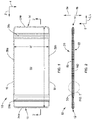
Figure 1 is a top view of a terry article according to an embodiment of the present disclosure; -
Figure 2 is a schematic cross-sectional view of the terry article shown inFigure 1 , shown along line 2-2; -
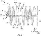
Figure 3 is a cross-sectional view of an encircled portion of the terry article shown inFigure 2 ; -
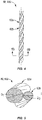
Figure 4 is a schematic side view of a two-ply yarn used to form the terry article shown inFigures 1-3 ; -
Figure 5 is a cross-sectional view of the two-ply yarn taken along line 5-5 inFigure 4 ; and -
Figure 6 is a process flow diagram illustrating process steps in the manufacture of the terry article shown inFigures 1-5 . - As shown in
Figures 1-3 , theterry article 10 includes aground component 30 and anupper pile component 60 and/or alower pile component 160. The upper andlower pile components piles first yarn 62a and asecond yarn 62b that are twisted together. Thefirst yarn 62a may have a first yarn count (or be a coarse yarn). Thesecond yarn 62b is primarily made of regenerated cellulose fibers and may have a second count that is less than (or finer) the first count. In other words, thefirst yarn 62a may be a coarse yarn and thesecond yarn 62b may be finer yarn made of regenerated cellulose fibers. The first yarn is typically made of cotton fibers but other fibers and fiber blends can be used as further explained below. The yarn configuration in the piles can yield aterry article 10 that is strong and absorbent, while also being soft and having sheen. The inventive terry articles and methods are surprisingly superior to existing so-called low-twist towels. In particular, there are challenges of weaving production and quality in 100% cotton low twist towels. The low yarn strength and elongation of the cotton yarns cannot withstand tension during weaving process. Apart from production problems, the softness of the 100% cotton low twist towels is inferior to the new inventive articles and methods as described herein. - The description and figures illustrate a towel article formed from a terry fabric as one example. However, terry articles—products made with or including terry fabrics—can include, but are not limited to, towels, bath robes, rugs, top of the bed fabrics, bath mats, and seat covers. The terry articles as described herein are suitable for home-uses, e.g. for products in bath or kitchen uses, commercial uses, such as towels designed for hotels, hospitality business, healthcare, and restaurants, and/or industrial uses.
- Referring to
Figure 1 , theterry article 10 includes afirst end 12 and asecond end 14 spaced from thefirst end 12 along alongitudinal direction 2, as well as afirst side 16 and asecond side 18. Both the first andsecond sides first end 12 to thesecond end 14 along thelongitudinal direction 2. Thelongitudinal direction 2 can also be referred to as the machine direction or the warp direction. The first andsecond sides longitudinal direction 2. The first and second ends 12 and 14 and first andsecond sides terry article 10. Theterry article 10 also includes anfirst side 20 and asecond side 22 opposed to thefirst side 20 along avertical direction 6 that is perpendicular to the longitudinal andlateral directions 2 and 4, respectively. Theterry article 10 has a length L that extends from thefirst end 12 to thesecond end 14 along thelongitudinal direction 2 and a width W that extends from thefirst side 16 to thesecond side 18 along the lateral direction 4. As illustrated, the length L of theterry article 10 is greater than the width W, so as to define the shape of a bath towel or hand towel. The dimensions of theterry article 10 can be defined during manufacturing to be any particular size. For instance, theterry article 10 can be sized as a hand towel, or theterry article 10 can be sized as a bath towel. - Continuing with
Figures 1-3 , theterry article 10 includes aground component 30 and at least one pile component. In the illustrated embodiment, theterry article 10 has anupper pile component 60 along thefirst side 20 of theterry article 10 and alower pile component 160 along thesecond side 22 of theterry article 10. In some instances, theterry article 10 includes only one pile component on either thefirst side 20 or thesecond side 22. The ground component;6 30 includes anfirst side 32 and asecond side 34 spaced from thefirst side 32 along thevertical direction 6. Theupper pile component 60 can project away from thefirst side 32 of theground component 30 along thevertical direction 6 in afirst direction 8a. Thelower pile component 160 can project from thesecond side 34 of theground component 30 along thevertical direction 6 in asecond direction 8b, which is opposite to thefirst direction 8a. Theupper pile component 60 may be referred to as a first pile component and thelower pile component 160 may be referred to as a second pile component. The first and second ends 12 and 14 of theterry article 10;6 includehems second sides selvages terry article 10 may also include one or more optional borders 28 that extend from thefirst side 16 to thesecond side 18, or from thefirst end 12 to thesecond end 14 of theterry article 10. For example, theterry article 10 shown inFigure 1 includes an optionalfirst border 28a and an optionalsecond border 28b. - As illustrated in
Figures 1-3 , theupper pile component 60 can extend across a majority (up to all) of thefirst side 20 of theterry article 10. Specifically, theupper pile component 60 may extend from thefirst end 12 to thesecond end 14. Theupper pile component 60 may also extend from onehem 26a at thefirst side 16 to the opposinghem 26b at thesecond side 18 along the lateral direction 4. Theupper pile component 60 therefore may define a substantial portion of thefirst side 20 of theterry article 10. Accordingly, theupper pile component 60 includes a plurality ofpiles 152a (up to all of the piles) located on thefirst side 32 of theground component 30. In addition, thelower pile component 160 may extend along one or both of longitudinal andlateral directions 2 and 4 on thesecond side 34 of theground component 30. As shown, thelower pile component 160 corresponds to theupper pile component 60 such thatlower pile component 160 defines a substantial portion of thesecond side 22 of theterry article 10. Accordingly, thelower pile component 160 includes a plurality ofpiles 152b (up to all of the piles) on thesecond side 34 of theground component 30. However, thelower pile component 160 may define any portion of thesecond side 22 of theterry article 10 as desired. - The
ground component 30 includes a plurality ofground warp yarns 40 and a plurality ofground weft yarns 42 interwoven with the plurality ofground warp yarns 40. As shown, theground warp yarns 40 may extend along a warp direction 5a, and theground weft yarns 42 may extend along a weft direction 5b. The warp direction 5a is parallel to thelongitudinal direction 2, while the weft direction 5b is parallel to the lateral direction 4. Theground component 30 may be defined by a number of woven structures. Exemplary woven structures for theground component 30 include, but are not limited to, 1×1 plain weave, 2×1 rib weave, 2×2 rib weave, or 3×1 rib weave. As further explained below, theground warp yarns 40 and theground weft yarns 42 may each comprise one or more of natural fiber and a synthetic fiber. For instance, each of theground warp yarns 40 may comprise natural fiber yarns, synthetic fiber yarns, or blended natural and synthetic fiber yarns. - The
ground warp yarns 40 can be formed from any number of fiber types. For instance, theground warp yarns 40 can be natural fiber yarns, synthetic fiber yarns, or natural and synthetic blended yarns. Synthetic yarns that have good moisture absorbency and/or moisture retention properties may in some instances be used to form theground warp yarns 40. The natural fiber yarns that may be used to form theground warp yarns 40 may include cotton fibers, flax, bamboo, hemp, or other natural fibers. Natural and synthetic blended yarns that may be used to form theground warp yarns 40 can include blends of cotton and polyethylene terephthalate (PET) staple fibers, cotton and polylactic acid (PLA) staple fibers, and cotton and polypropylene (PP) staple fibers. However, the present disclosure is not limited to cotton blends. Other natural and synthetic blends that can be utilized include cotton and staple microfibers, or cotton and staple fibers with complex cross-sectional shapes. In another example, the natural and synthetic blended yarns can include cotton fibers in a core-spun construction with a synthetic filament comprising the core. The synthetic yarns may include rayon fibers (e.g. Modal, Lyocell), microfiber staple fibers, or blends of PET and polyamide microfibers. - The
ground warp yarns 40 can be any type of spun yarn structure. For example theground warp yarns 40 can be ring spun yarns, open end yarns, rotor spun yarns, or filaments. In one embodiment, theground warp yarns 40 can be Hygrocotton® brand yarns marketed by Welspun India Limited. Furthermore, theground warp yarns 40 can be formed as disclosed inU.S. Patent No. 8,833,075 , entitled "Hygro Materials for Use In Making Yarns And Fabrics," (the '075 patent). The '075 patent is incorporated by reference into the present disclosure. The hygro yarns may comprise cotton fibers with an internal void or hollow core, and/or a porous structure. Theground warp yarns 40 may have a count in a range between about 98.33 Tex (6 Ne) to about 9.84 Tex (60 Ne). In one example, theground warp yarns 40 have a count of about 36.88 Tex (16 Ne). In another example, theground warp yarns 40 have a count of about 29.50 Tex (20 Ne). In another example, theground warp yarns 40 have a count of about 24.58 Tex (24 Ne). In another example, theground warp yarns 40 have a count of about 19.68 Tex (30 Ne). In another example, theground warp yarns 40 have a count of about 17.36 Tex (34 Ne). In another example, theground warp yarns 40 have a count of about 14.76 Tex (40 Ne). In another example, theground warp yarns 40 have a count of about 11.80 Tex (50 Ne). In addition, theground warp yarns 40 can be plied yarns. In one example, theground warp yarns 40 can include a 2-ply natural fiber yarn. In another example, theground warp yarns 40 can include a 3-ply yarn. - The
ground weft yarns 42 can be formed from a number of fiber types that have a variety of different yarn structures. For instance, theground weft yarns 42 can be natural fiber yarns, synthetic yarns, or natural and synthetic blended yarns. Theground weft yarns 42 can be ring spun yarns, open end yarns, rotor spun yarns, or filaments. Theground weft yarns 42 can also be Hygrocotton® brand yarns marketed by Welspun India Limited. Further, theground weft yarns 42 can be formed as disclosed in the '075 patent. Theground weft yarns 42 can have a count in a range between about 98.33 Tex (6 Ne) to about 9.84 Tex (60 Ne). In accordance with the illustrated embodiment, theground weft yarns 42 can be similar to theground warp yarns 40 described above. - Referring to
Figure 3-5 , the terry fabric include at least one pile component. As shown, the terry article includes upper andlower pile components lower piles ground component 30. Thepiles pile yarns ground component 30. Theupper pile yarn 154a and includes a pliedyarns 80. Thelower pile yarns 154b include plied yarns180. The pliedyarns lower pile components first side 20 and thesecond side 22 of theterry article 10. Thepiles lower pile components ground component 30 to the terminal ends of the piles. The pile height H can range from 2 up to 12 millimeters (or more). Though the pile heights H of the upper andlower pile components lower pile components - Referring to
Figures 4-5 , theupper pile component 60 and/or thelower pile component 160 may include a plied yarn made of a plurality of separate, packaged yarns twisted together into a plied yarn configuration. In one embodiment, the pliedyarn 80 comprises afirst yarn 62a and asecond yarn 62b twisted together into a plied yarn configuration. - The
first yarn 62a may be comprised of staple fibers. In one example, the staple fibers may be natural fibers, such as cotton fibers. Alternatively, and merely for example, in place of cotton, thefirst yarn 62a may contain viscose fibers, modal fibers, silk fibers, and acrylic fibers. In another example, the staple fibers may be synthetic fibers, such as acrylic fibers. Alternatively, and merely for example, in place of acrylic fibers, thefirst yarn 62a may contain polyethylene terephthalate (PET) fibers or polyamide fibers. In a further example, thefirst yarn 62a may include staple fibers that comprise a fiber blend, such as a blend of natural and synthetic fibers. The fiber blends that may be used in thefirst yarn 62a may include, for example: blends of cotton and bamboo; blends of cotton and sea weed fibers; blends of cotton and silver fibers; blends of cotton and charcoal fibers; blends of PET fibers and cotton; blends of PET and regenerated cellulose fibers; blends of cotton and modal; blends of cotton; silk and modal; and any combinations thereof. The blends of natural and synthetic fibers that may be used in thefirst yarn 62a can define a ratio of natural fibers to synthetic fibers that ranges from about 90:10 to about 10:90. Thefirst yarn 62a may also, for example, be 100% cotton or a combination of any of the foregoing blends. Additionally, thefirst yarn 62a may be preshrunk. Furthermore, thefirst yarn 62a can a hygro yarn formed as disclosed in the '075 patent. The '075 patent is incorporated by reference into the present disclosure. The hygro yarns may comprise cotton fibers with an internal void or hollow core, and/or a porous structure. - The
second yarn 62b may be comprised primarily of regenerated cellulosic fibers. Regenerated cellulose fibers may include viscose rayon fibers, modal, bamboo fibers, and like. In some instances, thesecond yarn 62b may comprise a blend that is predominantly regenerated cellulosic fibers and other fibers, including natural fibers or synthetic fibers. In such an example, thesecond yarn 62b can be at least 50% regenerated cellulosic fibers and the balance being one or more other fibers. Alternatively, thesecond yarn 62b can be from about 5 % to about 95% regenerated cellulosic fibers and 5% to about 95% of one or more other fibers. Further, thesecond yarn 62b may be preshrunk. - As shown in
Figure 5 , thefirst yarn 62a has a first yarn count, and thesecond yarn 62b has a second yarn count that is finer that the first yarn count. It should be appreciated that thefirst yarn 62a can define a first diameter D1 that is perpendicular to a central axis of theyarn 62a and thesecond yarn 62b defines a second diameter D2 perpendicular to a central axis of theyarn 62b. In the depicted embodiment, the second diameter D2 is smaller than the first diameter D1. As such, the second yarn count of thesecond yarn 62b is lower (i.e. finer) than the first yarn count of thefirst yarn 62a. The first and second yarn counts may be between 59.00 Tex (10 Ne) and 6.56 Tex (90 Ne). In one embodiment, the second yarn count can be between 9.84 Tex (60 Ne) and 6.56 Tex (90 Ne). In one embodiment, thefirst yarn 62a has a first yarn count less than 29.50 Tex (20 Ne), and thesecond yarn 62b has a second yarn count greater than 29.50 Tex (20 Ne). In another embodiment, thefirst yarn 62a has a first yarn count less than 19.68 Tex (30 Ne), and thesecond yarn 62b has a second yarn count greater than 19.68 Tex (30 Ne). In a further embodiment, thefirst yarn 62a has a first yarn count less than 14.76 Tex (40 Ne), and thesecond yarn 62b has a second yarn count greater than 14.76 Tex (40 Ne). In another embodiment, thefirst yarn 62a has a first yarn count less than 11.80 Tex (50 Ne), and thesecond yarn 62b has a second yarn count greater than 11.80 Tex (50 Ne). - The first and
second yarns second yarns second yarns second yarns first yarn 62a may be greater than the second twist multiplier of thesecond yarn 62b. In another embodiment, the second twist multiplier may be greater than the first twist multiplier. - As illustrated, the plied
yarn 80 is a two-ply yarn that includes afirst yarn 62a and asecond yarn 62b twisted together with thefirst yarn 62a. However, the pliedyarn 80 can have a number of alternative configurations compared to what is illustrated in the drawings and described further below. For instance, the pliedyarn 80 can have more than two separate packaged yarns. In one embodiment, the pliedyarn 80 can be 3-ply yarn that has three separate packaged dyed yarns. In another example, the pliedyarn 80 is a 4-ply yarn that has four separate packaged dyed yarns. In other example, the pliedyarn 80 is a 5-ply yarn that has five separate packaged dyed yarns. - Further examples of the plied
yarn 80 are described next. In one example, the pliedyarn 80 may include two yarns twisted together, where one of the two yarns comprises regenerated cellulosic fibers and the other of the two yarns is a staple yarn or a continuous filament yarn. In another example, the pliedyarn 80 has three yarns twisted together, where at least one of the three yarns comprises regenerated cellulosic fibers and the other yarns are staple yarns or continuous filament yarns. In yet another example, the pliedyarn 80 has four yarns twisted together, where at least one of the four yarns comprises regenerated cellulosic fibers and the other yarns are staple yarns or continuous filament yarns. In another example, the pliedyarn 80 has five yarns twisted together, wherein at least one of the five yarns comprises regenerated cellulosic fibers and the other yarns are staple yarns or continuous filament yarns. While the various configurations of the pliedyarn 80 are described above to illustrate different implementations, for ease of illustration the pliedyarn 80 is described herein and illustrated as a two-ply yarn having first andsecond yarns - A method of making a terry article according to an embodiment of the disclosure is illustrated in
Figure 6 . Themethod 200 includesyarn formation 210 for processing: a) theground warp yarns 40, b) theground weft yarns 42, and c) thepile yarn yarn 80. In embodiments where theterry article 10 includes upper andlower pile components yarn formation 210 can include the step of formingadditional pile yarns 154b for thelower pile component 160. Exemplary yarn formation phases will be described next. - During the
yarn formation 210, theground warp yarns 40 may be formed from any number of fiber types. Theground warp yarns 40 can be formed primarily with natural fibers, natural and synthetic blended fibers, and synthetic fibers or yarns with good moisture absorbency and/or retention properties. In one example, theground warp yarns 40 are formed primarily from natural fibers, such as cotton. - The
yarn formation 210 for theground warp yarns 40 can include various staple yarn spinning operations. Examples of such yarn spinning operations (not illustrated) may include bale opening, carding, combing, drafting, roving, and yarn spinning to the desired count and twist level. In some cases, theground warp yarns 40 can be plied into 2-ply, 3-ply, or 4-ply configurations. In one example, ring spinning is the preferred spinning system used in the groundwarp preparation step 220. However, theground warp yarns 40 can be formed open end spinning systems, rotor spun spinning systems, or vortex spinning systems. Furthermore, the groundwarp preparation step 220 may include methods to form the Hygrocotton®, as disclosed in the '075 patent. After theyarn formation 210, theground warp yarns 40 are wound into yarn packages for the groundwarp preparation step 220. - During
yarn formation 210, theground weft yarns 42 may be formed with similar fiber types and using the same or similar yarn spinning systems as those used to form theground warp yarns 40. As needed, theground weft yarns 42 may be plied in 2-ply, 3 ply, or 4-ply configurations. Following the spinning of theground weft yarns 42, theground weft yarns 42 are wound onto desired packages in theweft winding step 215. The wound packages are then staged for weft insertion during fabric formation steps 240, which are discussed further below. -
Yarn formation 210 also include includes forming the first andsecond yarns second yarns second yarns first yarns 62a may be formed from a variety of fiber types, such as natural fibers, synthetic fibers, or fiber blends as described above. Thesecond yarns 62b may be entirely comprised of regenerated cellulosic fibers, or may include a blend regenerated cellulosic fibers and other fiber types. Preferably, the second yarn at least 50% up to 100% of regenerated cellulosic fibers. - The
yarn formation 210 further includes forming the pliedyarns 80 for use in theupper pile component 60 and/orlower pile component 60 as piles 75. Interry articles 10 including both anupper pile component 60 and alower pile component 160, pliedyarns 80 are used in the upper and lower pile components. Forming plied yarns include twisting together thefirst yarn 62a and thesecond yarn 62b into a plied yarn configuration. As mentioned above, the first andsecond yarns yarns 80, the first andsecond yarns second yarns second yarns first yarn 62a andsecond yarn 62b are each twisted in the Z-direction and the two yarns are twisted together in the Z-direction. Forming the plied yarns can also include letting off excess amounts of thesecond yarn 62b, which can cause the plied yarns to be fuller and more open. As illustrated, the plied yarns formed in theyarn formation 210 may be the same for both the upper andlower pile components yarn formation 210 may be different for the upper andlower pile components yarn formation 210 can alternatively include plying the multiple sets of yarns into 3-ply or 4-ply configurations. - After
yarn formation 210, the method continues to aweft winding step 215. Theweft winding step 215 may include one or more steps, whereby the ground weft ends are removed from their respective yarn packages, arranged in a parallel form, and wound onto a ground weft beam. Theweft winding step 215 may also include a sizing step where a typical sizing agent is applied to each ground warp yarn to aid in fabric formation. - Following the
weft winding step 215, the method proceeds to a groundwarp preparation step 220 and a pilewarp preparation step 230. The groundwarp preparation step 220 includes one or more ground warping steps, whereby the ground yarn ends are removed from their respective yarn packages, arranged in a parallel form, and wound onto a ground warp beam. The groundwarp preparation step 220 also includes a sizing step where a typical sizing agent is applied to each ground warp yarn to aid in fabric formation. The groundwarp preparation step 220 results in a warp beam ofground warp yarns 40 prepared for weaving. The ground warp beam can be positioned on a mounting arm of a weaving loom so that the ground warp yarns can be drawn through the loom components, as further described below. - The pile
warp preparation step 230 includes similar steps to the ground warp preparation steps 220, i.e., warping and sizing. In particular, the pilewarp preparation step 230 includes the steps of warping and sizing the pile yarns 75. For embodiments ofterry articles 10 that include upper andlower pile components warp preparation step 230 includes preparing two separate pile warp beams: one upper pile warp beam and one lower pile warp beam. The upper pile warp beam is dedicated to forming theupper pile component 60, and the one lower pile warp beam is dedicated to forming thelower pile component 160. The ground and pile warp beams are positioned on respective mounting arms or mounting brackets proximate the weaving loom (not shown). - Continuing with
Figure 6 ,fabric formation 240 includes forming theground component 30 and theupper pile component 60 and/orlower pile component 160 using a weaving loom designed for terry weaving. More specifically, infabric formation 240, eachground warp yarn 40 and pile warp yarn from the respective warp beams are drawn-in (not shown) through various components of a weaving loom, such as drop wires, heddle eyes attached to a respective harness, reed and reed dents, in a designated order as is known in the art. - After drawing-in is complete, the
fabric formation 240 proceeds through two phases: a ground component formation phase and a pile component formation phase. Both phases include a particular shedding motion to facilitate interweaving theground weft yarns 42 with theground warp yarns 40 and pile warp yarns to create the desired pile fabric construction. For instance, shedding motions can include cam shedding, dobby shedding, or jacquard shedding motions, each of which can cause the selective raising and lowering of warp ends to create an open shed for weft insertion. In one example, the weaving loom may be configured for one type of shedding motion for the ground warp yarns and another type of shedding motion for the pile warp yarns. For instance, a cam or dobby shedding motion can be used for the ground warp yarns and the jacquard shedding motions can be used for the pile warp yarns. A specific reed motion and warp take-off system is utilized to form the piles during the pile component phase and such a mechanism using a terry weaving loom is well known and will not be repeated here. - During the ground component phase of the fabric formation steps 240, the
ground weft yarns 42 are interwoven with theground warp yarns 40 to define theground component 30 or ground fabric. Exemplary ground fabric woven constructions include: a 1×1 plain weave, 2×1 rib weave, 2×2 rib weave, or 3×1 rib weave. Other woven constructions in the ground fabric are possible as well. The ground component formation phase can utilize different weft insertion techniques, including air-jet, rapier, or projectile type weft (fill) insertion techniques. - The pile component phase of the fabric formation steps 240 include interweaving the pile yarns 75 (via the first warp) with the ground warp and
weft yarns piles 152a that extend away from theground component 30 along thevertical direction 6. Because pliedyarns 80 are used to create thepiles 152a, thepiles 152a may have a spiral shape. The fabric formation can also include forming a second set ofpiles 152b that extend away from theground component 30 along thevertical direction 6. The fabric formation steps 240 can further include optional step of weaving one or more borders 28 (such as first andsecond borders hems - The fabric formation steps 240 can be used to form pile fabrics having any number of different fabric constructions. In one example, the pile fabric is formed to result in a 3-pick up to 7-pick (or more) terry weave pattern. Furthermore, the pile fabric can have a 1:1 warp order where each ground warp end is followed by a pile warp end across the width of the pile fabric. In other embodiments, the pile fabric can have a 2:2 warp order where a pair of ground warp ends are followed by a pair of pile warp ends across the width of the pile fabric. In one example, the pile fabric can be formed to include between about 15 to about 45 ends/cm, preferably between about 20 and 30 ends/cm. The weft or pick density can range between about 10 picks/cm to about 30 picks/cm. Preferably, the pick density is between about 15 picks/cm to about 25 picks/cm.
- In embodiments with upper and
lower pile components upper pile component 60 on thefirst side 32 of theground component 30 and forming thelower pile component 160 on thesecond side 34 of theground component 30. As noted above, the upper andlower pile components pile yarns yarns - Following fabric formation steps 240, the pile fabric is subjected to a
post-formation processing step 250. Thepost-formation processing step 250, may also include a de-sizing step, a bleaching step, a dyeing step, and/or a washing step. In another example, thepost-formation processing step 250 includes a dyeing phase. For instance, the dyeing phase may include applying reactive dyes to natural fiber yarns, and cotton yarns in particular, at elevated temperatures sufficient to cause yarn shrinkage. Either batch, semi-continuous, or continuous dyeing systems can be used to apply reactive dyes to the pile fabric. Other dyes can be used depending on the particular fiber blend. The dyeing and finishing phase could also include printing as needed. - The
post-formation processing step 250 may also include a finishing phase where various functional finishes or agents are added to the pile fabric to improve or augment performance characteristics of theterry article 10. In one example, the pile fabric can be treated with a hydrophilic agent, such as silicones. In another example, the finishing step includes application of one or more softeners to the fabric, such as cationic softeners, non-ionic softeners, and silicones. In another example, the finishing step includes application of an antimicrobial agent to the pile fabric. In accordance with one embodiment, the finishing step could also include the thermal treatment that causes shrinkage of the piles 85. In accordance with one embodiment, after the dyeing and finishing phases of thepost-formation processing step 250, a drying step is used to remove moisture from the pile fabric. The drying step also includes a thermal treatment step that can cause shrinkage of the continuous filament yarns that may cause the second set of piles to shrink. For example, when the pile fabrics include non-heat set yarns inpile components - It should be appreciated that in some case, dyes and functional finishes can be applied to the fabric in any particular order. For example, functional agents can be applied along with the application of the dyes, before application of the dyes, or after application on the dyes. It should be appreciated that dyeing, finishing, and drying phases of
step 250 may be in-line and considering a continuous process step. - Following the
post-formation processing step 250, the method includes a cuttingstep 270 where the pile fabric is cut to the size of one ormore terry articles 10, such as a bath towel, a hand towel, and a washcloth. Following the cuttingstep 270, additional edge binding or hems (such ashems step 280 places thefinished terry articles 10 in suitable packaging for shipment. - Another exemplary method of making a terry article includes spinning a first yarn to have a first yarn count and spinning a second yarn to have a second yarn count that is finer than the first yarn count, wherein the second yarn includes regenerated cellulosic fibers. The method may include plying the first yarn and the second yarn together to form a plied yarn. The method further includes weaving a pile fabric including a ground component and a pile component disposed on at least one of an first side and a second side of the ground component, wherein the pile component comprises a plurality of piles formed with the plied yarn such that each pile includes 1) a first yarn having the first yarn count, and 2) a second yarn having the second yarn count that is finer than the first yarn count. As noted above, the first yarn includes natural fibers. In another example, the first yarn includes cotton fibers. In yet another example, the first yarn includes synthetic fibers. In yet another example, the first yarn includes a blend of natural and synthetic fibers. In one example, the second yarn is primarily regenerated cellulose fibers. In yet another example, the second yarn includes a blend of the regenerated cellulose fibers and one or more of synthetic fibers and natural fibers.
- Exemplary constructions consistent with the present disclosure were formed and various tests were performed to evaluate the properties of the such constructions. Table 1 below illustrates the data obtained from for an exemplar plied yarn used in the piles. Example A includes a 45.39 Tex (1/13 Ne) combed cotton yarn as the
first yarn 62a in the piles and a 9.84 Tex (60 Ne) regenerated cellulose yarns as thesecond yarn 62b in piles. Example B includes a 45.39 Tex (1/13 Ne) combed cotton yarn as thefirst yarn 62a in the piles and a 9.84 Tex (60 Ne) cotton yarn as thesecond yarn 62b. The yarns summarized below were used to manufacture pile fabrics as disclosed herein.Table 1 Test Data Example A Example B Wrapping Test Results Average Count for the Plied Yarn 55.45 Tex (10.64 Ne) 53.73 Tex (10.98 Ne) Avg. Strength 241.43 157.3 Count Cv% 0.44 0.98 Strength Cv % 1.22 1.42 T.P.M. (T.P.I.)Test Results Average T.P.M. (T.P.I.) 333.07 (8.46) 338.98 (8.61) T.P.M. (T.P.I.) Cv% 1.93 0.75 T.M 2.59 2.6 UTR-3 Test Results Avg. BF (gms) 986.3 602.1 Avg. gf/tex (R.Km (Nm∗ Kgf)). 17.77 (17.77) 11.2 (11.2) Min. gf/tex (R.Km (Nm∗ Kgf)). 15.73 (15.73) 9.26 (9.26) gf/tex (R.Km) Cv % 6.2 (6.2) 11.17 (11.17) Elongation % 7.6 3.35 Elongation Cv % 9.37 8.1 - While the disclosure is described herein using a limited number of embodiments, these specific embodiments are not intended to limit the scope of the disclosure as otherwise described and claimed herein. The precise arrangement of various elements and order of articles and methods described herein are not to be considered limiting. For instance, although the steps of the methods are described with reference to sequential series of reference signs and progression of the blocks in the figures, the method can be implemented in any particular order, as desired.
Claims (11)
- A terry article (10) comprising:a ground component (30) including a plurality of ground warp yarns and a plurality of ground weft yarns interwoven with the plurality of ground warp yarns, the ground component (30) including a first side (32) and a second side (34) opposite to the first side along a vertical direction, perpendicular to longitudinal and lateral directions of the terry article (10); anda pile component (60, 160) having a plurality of plied yarns (80), each of the plied yarns including 1) a first yarn that has a first yarn count, and 2) a second yarn that has a second yarn count that is finer than the first yarn count,characterised in that the pile component extends away from the ground component along a vertical direction and the second yarn comprises regenerated cellulose fibers.
- The terry article (10) of claim 1, wherein the first yarn comprises natural fibers.
- The terry article (10) of claim 1 or claim 2, wherein the first yarn comprises cotton fibers.
- The terry article (10) of any of claims 1 to 3, wherein the first yarn comprises synthetic fibers.
- The terry article (10) of any of claims 1 to 4, wherein the first yarn comprises a blend of natural and synthetic fibers.
- The terry article (10) of any of claims 1 to 5, wherein the second yarn is primarily regenerated cellulose fibers.
- The terry article (10) of any of claims 1 to 5, wherein the second yarn comprises a blend of the regenerated cellulose fibers and one or more of synthetic fibers and natural fibers.
- The terry article (10) of any of claims 1 to 7, wherein the first yarn has a count that is between 59.00 Tex (10 Ne) and 7.38 Tex (80 Ne).
- The terry article (10) of any of claims 1 to 8, wherein the second yarn has a count that is between 98.33 Tex (6 Ne) and 6.56 Tex (90 Ne).
- The terry article (10) of any of claims 1 to 9, wherein, in the pile yarn, each of the first yarn and the second yarn are twisted in one of an S direction and a Z direction, and the plied yarn is twisted together in the other of the S direction and Z direction.
- The terry article (10) of any of claims 1 to 10, wherein the pile component is an upper pile component (60) that is disposed on the first side (32), wherein the terry article (10) further comprises a lower pile component (160) extending away from the second side (34) of the ground component (30) along the vertical direction.
Priority Applications (1)
| Application Number | Priority Date | Filing Date | Title |
|---|---|---|---|
| PL19158393T PL3530786T3 (en) | 2018-02-21 | 2019-02-20 | Soft twist terry article |
Applications Claiming Priority (1)
| Application Number | Priority Date | Filing Date | Title |
|---|---|---|---|
| IN201821006589 | 2018-02-21 |
Publications (2)
| Publication Number | Publication Date |
|---|---|
| EP3530786A1 EP3530786A1 (en) | 2019-08-28 |
| EP3530786B1 true EP3530786B1 (en) | 2021-08-25 |
Family
ID=65529445
Family Applications (1)
| Application Number | Title | Priority Date | Filing Date |
|---|---|---|---|
| EP19158393.9A Active EP3530786B1 (en) | 2018-02-21 | 2019-02-20 | Soft twist terry article |
Country Status (5)
| Country | Link |
|---|---|
| US (2) | US11021816B2 (en) |
| EP (1) | EP3530786B1 (en) |
| DK (1) | DK3530786T3 (en) |
| ES (1) | ES2895488T3 (en) |
| PL (1) | PL3530786T3 (en) |
Families Citing this family (8)
| Publication number | Priority date | Publication date | Assignee | Title |
|---|---|---|---|---|
| US11441246B2 (en) | 2013-05-28 | 2022-09-13 | Uchino Co., Ltd. | Towel product |
| US11021816B2 (en) | 2018-02-21 | 2021-06-01 | Welspun India Limited | Soft twist terry article |
| CN111058157B (en) * | 2019-12-16 | 2021-08-06 | 建德鑫鼎纤维材料有限公司 | Warp looped fabric with firm loop consolidation and weaving method thereof |
| WO2022051475A1 (en) * | 2020-09-03 | 2022-03-10 | Loftex Usa Llc | Composite low-twist yarn towel and production method thereof |
| JP6968464B2 (en) * | 2020-09-15 | 2021-11-17 | 伊澤タオル株式会社 | Terry cloth and its manufacturing method |
| US11639564B1 (en) | 2022-07-15 | 2023-05-02 | Wetsox, LLC | Twisted yarns and methods of manufacture thereof |
| JP7372718B1 (en) * | 2023-04-25 | 2023-11-01 | 伊澤タオル株式会社 | Towel fabric and its manufacturing method |
| US20250305188A1 (en) * | 2024-03-29 | 2025-10-02 | Target Brands, Inc. | Plied yarns constructed from different fiber types and methods of forming the plied yarns |
Family Cites Families (26)
| Publication number | Priority date | Publication date | Assignee | Title |
|---|---|---|---|---|
| US3940522A (en) * | 1971-05-27 | 1976-02-24 | E. I. Du Pont De Nemours And Company | Synthetic fibers and pile fabrics made therefrom |
| US3721272A (en) * | 1971-12-30 | 1973-03-20 | Fieldcrest Mills Inc | Terry fabric having high-low pile |
| EP0030566B1 (en) * | 1979-12-06 | 1986-07-30 | Toray Industries, Inc. | Pile fabric |
| US5555565A (en) * | 1995-06-23 | 1996-09-17 | Tanner Lynx Corporation | Thick pile sock with heterogeneous body and foot portions, and sock system therewith |
| US5667865A (en) * | 1996-06-26 | 1997-09-16 | Fieldcrest Cannon, Inc. | Terry fabric with increased rate of absorbency and method of forming same |
| US6537640B1 (en) * | 1998-03-25 | 2003-03-25 | Teijin Limited | Pile fabric |
| US20020119281A1 (en) * | 2000-11-24 | 2002-08-29 | Higgins Kenneth B. | Textile product and method |
| US20020142126A1 (en) * | 2000-11-24 | 2002-10-03 | Higgins Kenneth B. | Textile product and method |
| JP4139732B2 (en) * | 2003-05-15 | 2008-08-27 | 株式会社日立製作所 | Rubbing cloth material for LCD panel manufacturing |
| US20060037154A1 (en) * | 2004-08-19 | 2006-02-23 | Goineau Andre M | Multi-colored pile fabric and process |
| US7428772B2 (en) * | 2005-05-19 | 2008-09-30 | Mmi-Ipco, Llc | Engineered fabric articles |
| ES2413780T3 (en) * | 2005-10-17 | 2013-07-17 | Welspun Uk Limited | Hygroscopic materials for use in the manufacture of threads and fabrics |
| CN101126190B (en) | 2007-09-25 | 2011-02-16 | 山东滨州亚光毛巾有限公司 | Method for producing untwisted towel |
| US8156967B2 (en) * | 2009-04-15 | 2012-04-17 | JC Penney Private Brands, Inc. | Quick-dry textured towel |
| PT2562299T (en) * | 2010-04-20 | 2024-01-08 | Kuraray Trading Co Ltd | Bulking yarn and wound yarn for production of woven or knit fabric, woven or knit fabric, and production method for same |
| US8601811B2 (en) | 2010-09-09 | 2013-12-10 | Ford Global Technologies, Llc | Method and system adjusting an exhaust heat recovery valve |
| CA2753489C (en) * | 2010-09-24 | 2014-06-10 | Trident Limited | Air rich yarn and fabric and its method of manufacturing |
| DE102013101470B4 (en) * | 2013-02-14 | 2019-09-26 | Hanshin Towel, Co., Ltd | Method of making a multi-layered towel having a terry structure using a bamboo fiber and a multi-layered towel made therewith |
| WO2016103281A1 (en) * | 2014-12-22 | 2016-06-30 | Welspun India Limited | "rapid drying woven terry fabric and related articles" |
| US9524589B1 (en) * | 2015-08-31 | 2016-12-20 | Welspun India Limited | Interactive textile article and augmented reality system |
| US9828704B2 (en) * | 2015-09-10 | 2017-11-28 | Welspun India Limited | Terry article with synthetic filament yarns and method of making same |
| GB2544864B (en) * | 2015-09-30 | 2018-06-06 | Trident Ltd | Pile fabric and methods for manufacture of the same |
| US10240283B2 (en) * | 2015-12-07 | 2019-03-26 | Trident Limited | Fabric and method of manufacturing fabric |
| US20170167060A1 (en) * | 2015-12-10 | 2017-06-15 | Jennifer Daley | Ultra-high-quality towel and yarn used to weave it |
| US11486065B2 (en) * | 2017-06-06 | 2022-11-01 | Welspun India Limited | Hygro terry structures, articles, and related processes |
| US11021816B2 (en) | 2018-02-21 | 2021-06-01 | Welspun India Limited | Soft twist terry article |
-
2018
- 2018-09-26 US US16/142,561 patent/US11021816B2/en active Active
-
2019
- 2019-02-20 ES ES19158393T patent/ES2895488T3/en active Active
- 2019-02-20 PL PL19158393T patent/PL3530786T3/en unknown
- 2019-02-20 EP EP19158393.9A patent/EP3530786B1/en active Active
- 2019-02-20 DK DK19158393.9T patent/DK3530786T3/en active
-
2021
- 2021-05-28 US US17/333,928 patent/US11702774B2/en active Active
Non-Patent Citations (1)
| Title |
|---|
| None * |
Also Published As
| Publication number | Publication date |
|---|---|
| US20210285134A1 (en) | 2021-09-16 |
| DK3530786T3 (en) | 2021-10-25 |
| PL3530786T3 (en) | 2022-01-17 |
| US20190257011A1 (en) | 2019-08-22 |
| EP3530786A1 (en) | 2019-08-28 |
| US11702774B2 (en) | 2023-07-18 |
| US11021816B2 (en) | 2021-06-01 |
| ES2895488T3 (en) | 2022-02-21 |
Similar Documents
| Publication | Publication Date | Title |
|---|---|---|
| EP3530786B1 (en) | Soft twist terry article | |
| US10072364B2 (en) | Rapid drying woven terry fabric and related articles | |
| US9828704B2 (en) | Terry article with synthetic filament yarns and method of making same | |
| US20180080151A1 (en) | Performance fabrics and related articles | |
| CN109371529B (en) | Design and preparation method of double-layer functional fabric | |
| US10683593B2 (en) | Pile fabric and methods for manufacture of the same | |
| EP3141643B1 (en) | Terry article with synthetic filament yarns and method of making same | |
| JP6968464B2 (en) | Terry cloth and its manufacturing method | |
| EP3147395A1 (en) | Chambray fabric, bedding articles, and related manufacturing methods | |
| CN105755641A (en) | High-density fabric produced from high-shrinkage filaments and production method thereof | |
| WO2013074539A1 (en) | Woven fabric made of twisted yarns and method of manufacture thereof | |
| CN112853569A (en) | Preparation method of super-elastic multilayer fabric and super-elastic multilayer fabric | |
| CN114411307A (en) | Technology for manufacturing twistless sandwich gauze kerchief | |
| JP2010229584A (en) | Composite twisted yarn and woven or knitted fabric using this composite twisted yarn | |
| EP3992337B1 (en) | Terry article and method of making same | |
| CN218910679U (en) | Multi-fiber antique jean fabric and antique effect jean garment | |
| CN215051013U (en) | Double-faced satin fabric with silk luster | |
| JP7588009B2 (en) | Method for manufacturing double-twisted yarn and knitted or woven fabrics using the same | |
| CN107299452B (en) | Silk-like knitted fabric | |
| JP2001064839A (en) | Long and short composite yarn | |
| CN110685061A (en) | Imitated silk knitted fabric and preparation method thereof | |
| CN214572494U (en) | Machine-washable real silk and acetate fiber blended fabric | |
| US20250188654A1 (en) | Terry structure with selectively composite twist in pile and process of manufacturing | |
| CN114214776B (en) | Knitted-loop-like fabric and weaving process thereof | |
| JP7388937B2 (en) | Breathable fabric, its manufacturing method, and clothing using the same |
Legal Events
| Date | Code | Title | Description |
|---|---|---|---|
| PUAI | Public reference made under article 153(3) epc to a published international application that has entered the european phase |
Free format text: ORIGINAL CODE: 0009012 |
|
| STAA | Information on the status of an ep patent application or granted ep patent |
Free format text: STATUS: THE APPLICATION HAS BEEN PUBLISHED |
|
| AK | Designated contracting states |
Kind code of ref document: A1 Designated state(s): AL AT BE BG CH CY CZ DE DK EE ES FI FR GB GR HR HU IE IS IT LI LT LU LV MC MK MT NL NO PL PT RO RS SE SI SK SM TR |
|
| AX | Request for extension of the european patent |
Extension state: BA ME |
|
| STAA | Information on the status of an ep patent application or granted ep patent |
Free format text: STATUS: REQUEST FOR EXAMINATION WAS MADE |
|
| 17P | Request for examination filed |
Effective date: 20200209 |
|
| RBV | Designated contracting states (corrected) |
Designated state(s): AL AT BE BG CH CY CZ DE DK EE ES FI FR GB GR HR HU IE IS IT LI LT LU LV MC MK MT NL NO PL PT RO RS SE SI SK SM TR |
|
| STAA | Information on the status of an ep patent application or granted ep patent |
Free format text: STATUS: EXAMINATION IS IN PROGRESS |
|
| 17Q | First examination report despatched |
Effective date: 20200610 |
|
| GRAP | Despatch of communication of intention to grant a patent |
Free format text: ORIGINAL CODE: EPIDOSNIGR1 |
|
| STAA | Information on the status of an ep patent application or granted ep patent |
Free format text: STATUS: GRANT OF PATENT IS INTENDED |
|
| INTG | Intention to grant announced |
Effective date: 20210406 |
|
| RIN1 | Information on inventor provided before grant (corrected) |
Inventor name: SHARMA, RAJENDER Inventor name: GOENKA, DIPALI |
|
| GRAS | Grant fee paid |
Free format text: ORIGINAL CODE: EPIDOSNIGR3 |
|
| GRAA | (expected) grant |
Free format text: ORIGINAL CODE: 0009210 |
|
| STAA | Information on the status of an ep patent application or granted ep patent |
Free format text: STATUS: THE PATENT HAS BEEN GRANTED |
|
| AK | Designated contracting states |
Kind code of ref document: B1 Designated state(s): AL AT BE BG CH CY CZ DE DK EE ES FI FR GB GR HR HU IE IS IT LI LT LU LV MC MK MT NL NO PL PT RO RS SE SI SK SM TR |
|
| REG | Reference to a national code |
Ref country code: CH Ref legal event code: EP |
|
| REG | Reference to a national code |
Ref country code: IE Ref legal event code: FG4D Ref country code: AT Ref legal event code: REF Ref document number: 1423899 Country of ref document: AT Kind code of ref document: T Effective date: 20210915 |
|
| REG | Reference to a national code |
Ref country code: DE Ref legal event code: R096 Ref document number: 602019007040 Country of ref document: DE |
|
| REG | Reference to a national code |
Ref country code: DK Ref legal event code: T3 Effective date: 20211019 |
|
| REG | Reference to a national code |
Ref country code: SE Ref legal event code: TRGR |
|
| REG | Reference to a national code |
Ref country code: NL Ref legal event code: FP |
|
| REG | Reference to a national code |
Ref country code: LT Ref legal event code: MG9D |
|
| PG25 | Lapsed in a contracting state [announced via postgrant information from national office to epo] |
Ref country code: FI Free format text: LAPSE BECAUSE OF FAILURE TO SUBMIT A TRANSLATION OF THE DESCRIPTION OR TO PAY THE FEE WITHIN THE PRESCRIBED TIME-LIMIT Effective date: 20210825 Ref country code: RS Free format text: LAPSE BECAUSE OF FAILURE TO SUBMIT A TRANSLATION OF THE DESCRIPTION OR TO PAY THE FEE WITHIN THE PRESCRIBED TIME-LIMIT Effective date: 20210825 Ref country code: PT Free format text: LAPSE BECAUSE OF FAILURE TO SUBMIT A TRANSLATION OF THE DESCRIPTION OR TO PAY THE FEE WITHIN THE PRESCRIBED TIME-LIMIT Effective date: 20211227 Ref country code: NO Free format text: LAPSE BECAUSE OF FAILURE TO SUBMIT A TRANSLATION OF THE DESCRIPTION OR TO PAY THE FEE WITHIN THE PRESCRIBED TIME-LIMIT Effective date: 20211125 Ref country code: HR Free format text: LAPSE BECAUSE OF FAILURE TO SUBMIT A TRANSLATION OF THE DESCRIPTION OR TO PAY THE FEE WITHIN THE PRESCRIBED TIME-LIMIT Effective date: 20210825 Ref country code: BG Free format text: LAPSE BECAUSE OF FAILURE TO SUBMIT A TRANSLATION OF THE DESCRIPTION OR TO PAY THE FEE WITHIN THE PRESCRIBED TIME-LIMIT Effective date: 20211125 Ref country code: LT Free format text: LAPSE BECAUSE OF FAILURE TO SUBMIT A TRANSLATION OF THE DESCRIPTION OR TO PAY THE FEE WITHIN THE PRESCRIBED TIME-LIMIT Effective date: 20210825 |
|
| REG | Reference to a national code |
Ref country code: ES Ref legal event code: FG2A Ref document number: 2895488 Country of ref document: ES Kind code of ref document: T3 Effective date: 20220221 |
|
| PG25 | Lapsed in a contracting state [announced via postgrant information from national office to epo] |
Ref country code: LV Free format text: LAPSE BECAUSE OF FAILURE TO SUBMIT A TRANSLATION OF THE DESCRIPTION OR TO PAY THE FEE WITHIN THE PRESCRIBED TIME-LIMIT Effective date: 20210825 Ref country code: GR Free format text: LAPSE BECAUSE OF FAILURE TO SUBMIT A TRANSLATION OF THE DESCRIPTION OR TO PAY THE FEE WITHIN THE PRESCRIBED TIME-LIMIT Effective date: 20211126 |
|
| PGFP | Annual fee paid to national office [announced via postgrant information from national office to epo] |
Ref country code: IE Payment date: 20220228 Year of fee payment: 4 Ref country code: DK Payment date: 20220222 Year of fee payment: 4 |
|
| REG | Reference to a national code |
Ref country code: DE Ref legal event code: R097 Ref document number: 602019007040 Country of ref document: DE |
|
| PG25 | Lapsed in a contracting state [announced via postgrant information from national office to epo] |
Ref country code: SM Free format text: LAPSE BECAUSE OF FAILURE TO SUBMIT A TRANSLATION OF THE DESCRIPTION OR TO PAY THE FEE WITHIN THE PRESCRIBED TIME-LIMIT Effective date: 20210825 Ref country code: SK Free format text: LAPSE BECAUSE OF FAILURE TO SUBMIT A TRANSLATION OF THE DESCRIPTION OR TO PAY THE FEE WITHIN THE PRESCRIBED TIME-LIMIT Effective date: 20210825 Ref country code: RO Free format text: LAPSE BECAUSE OF FAILURE TO SUBMIT A TRANSLATION OF THE DESCRIPTION OR TO PAY THE FEE WITHIN THE PRESCRIBED TIME-LIMIT Effective date: 20210825 Ref country code: EE Free format text: LAPSE BECAUSE OF FAILURE TO SUBMIT A TRANSLATION OF THE DESCRIPTION OR TO PAY THE FEE WITHIN THE PRESCRIBED TIME-LIMIT Effective date: 20210825 Ref country code: CZ Free format text: LAPSE BECAUSE OF FAILURE TO SUBMIT A TRANSLATION OF THE DESCRIPTION OR TO PAY THE FEE WITHIN THE PRESCRIBED TIME-LIMIT Effective date: 20210825 Ref country code: AL Free format text: LAPSE BECAUSE OF FAILURE TO SUBMIT A TRANSLATION OF THE DESCRIPTION OR TO PAY THE FEE WITHIN THE PRESCRIBED TIME-LIMIT Effective date: 20210825 |
|
| PGFP | Annual fee paid to national office [announced via postgrant information from national office to epo] |
Ref country code: SE Payment date: 20220222 Year of fee payment: 4 Ref country code: NL Payment date: 20220222 Year of fee payment: 4 Ref country code: IT Payment date: 20220228 Year of fee payment: 4 |
|
| PLBE | No opposition filed within time limit |
Free format text: ORIGINAL CODE: 0009261 |
|
| STAA | Information on the status of an ep patent application or granted ep patent |
Free format text: STATUS: NO OPPOSITION FILED WITHIN TIME LIMIT |
|
| PGFP | Annual fee paid to national office [announced via postgrant information from national office to epo] |
Ref country code: ES Payment date: 20220517 Year of fee payment: 4 |
|
| 26N | No opposition filed |
Effective date: 20220527 |
|
| PG25 | Lapsed in a contracting state [announced via postgrant information from national office to epo] |
Ref country code: SI Free format text: LAPSE BECAUSE OF FAILURE TO SUBMIT A TRANSLATION OF THE DESCRIPTION OR TO PAY THE FEE WITHIN THE PRESCRIBED TIME-LIMIT Effective date: 20210825 |
|
| PGFP | Annual fee paid to national office [announced via postgrant information from national office to epo] |
Ref country code: CH Payment date: 20220517 Year of fee payment: 4 |
|
| PG25 | Lapsed in a contracting state [announced via postgrant information from national office to epo] |
Ref country code: MC Free format text: LAPSE BECAUSE OF FAILURE TO SUBMIT A TRANSLATION OF THE DESCRIPTION OR TO PAY THE FEE WITHIN THE PRESCRIBED TIME-LIMIT Effective date: 20210825 |
|
| REG | Reference to a national code |
Ref country code: BE Ref legal event code: MM Effective date: 20220228 |
|
| PG25 | Lapsed in a contracting state [announced via postgrant information from national office to epo] |
Ref country code: LU Free format text: LAPSE BECAUSE OF NON-PAYMENT OF DUE FEES Effective date: 20220220 |
|
| PG25 | Lapsed in a contracting state [announced via postgrant information from national office to epo] |
Ref country code: BE Free format text: LAPSE BECAUSE OF NON-PAYMENT OF DUE FEES Effective date: 20220228 |
|
| REG | Reference to a national code |
Ref country code: AT Ref legal event code: UEP Ref document number: 1423899 Country of ref document: AT Kind code of ref document: T Effective date: 20210825 |
|
| REG | Reference to a national code |
Ref country code: DK Ref legal event code: EBP Effective date: 20230228 |
|
| REG | Reference to a national code |
Ref country code: CH Ref legal event code: PL |
|
| REG | Reference to a national code |
Ref country code: SE Ref legal event code: EUG |
|
| REG | Reference to a national code |
Ref country code: NL Ref legal event code: MM Effective date: 20230301 |
|
| PG25 | Lapsed in a contracting state [announced via postgrant information from national office to epo] |
Ref country code: SE Free format text: LAPSE BECAUSE OF NON-PAYMENT OF DUE FEES Effective date: 20230221 Ref country code: LI Free format text: LAPSE BECAUSE OF NON-PAYMENT OF DUE FEES Effective date: 20230228 Ref country code: CH Free format text: LAPSE BECAUSE OF NON-PAYMENT OF DUE FEES Effective date: 20230228 |
|
| PG25 | Lapsed in a contracting state [announced via postgrant information from national office to epo] |
Ref country code: NL Free format text: LAPSE BECAUSE OF NON-PAYMENT OF DUE FEES Effective date: 20230301 |
|
| REG | Reference to a national code |
Ref country code: IE Ref legal event code: MM4A |
|
| PG25 | Lapsed in a contracting state [announced via postgrant information from national office to epo] |
Ref country code: IT Free format text: LAPSE BECAUSE OF NON-PAYMENT OF DUE FEES Effective date: 20230220 Ref country code: IE Free format text: LAPSE BECAUSE OF NON-PAYMENT OF DUE FEES Effective date: 20230220 Ref country code: DK Free format text: LAPSE BECAUSE OF NON-PAYMENT OF DUE FEES Effective date: 20230228 |
|
| REG | Reference to a national code |
Ref country code: ES Ref legal event code: FD2A Effective date: 20240327 |
|
| PG25 | Lapsed in a contracting state [announced via postgrant information from national office to epo] |
Ref country code: ES Free format text: LAPSE BECAUSE OF NON-PAYMENT OF DUE FEES Effective date: 20230221 |
|
| PG25 | Lapsed in a contracting state [announced via postgrant information from national office to epo] |
Ref country code: MK Free format text: LAPSE BECAUSE OF FAILURE TO SUBMIT A TRANSLATION OF THE DESCRIPTION OR TO PAY THE FEE WITHIN THE PRESCRIBED TIME-LIMIT Effective date: 20210825 Ref country code: ES Free format text: LAPSE BECAUSE OF NON-PAYMENT OF DUE FEES Effective date: 20230221 Ref country code: CY Free format text: LAPSE BECAUSE OF FAILURE TO SUBMIT A TRANSLATION OF THE DESCRIPTION OR TO PAY THE FEE WITHIN THE PRESCRIBED TIME-LIMIT Effective date: 20210825 |
|
| PG25 | Lapsed in a contracting state [announced via postgrant information from national office to epo] |
Ref country code: PL Free format text: LAPSE BECAUSE OF NON-PAYMENT OF DUE FEES Effective date: 20220220 Ref country code: HU Free format text: LAPSE BECAUSE OF FAILURE TO SUBMIT A TRANSLATION OF THE DESCRIPTION OR TO PAY THE FEE WITHIN THE PRESCRIBED TIME-LIMIT; INVALID AB INITIO Effective date: 20190220 |
|
| PG25 | Lapsed in a contracting state [announced via postgrant information from national office to epo] |
Ref country code: MT Free format text: LAPSE BECAUSE OF FAILURE TO SUBMIT A TRANSLATION OF THE DESCRIPTION OR TO PAY THE FEE WITHIN THE PRESCRIBED TIME-LIMIT Effective date: 20210825 |
|
| REG | Reference to a national code |
Ref country code: AT Ref legal event code: MM01 Ref document number: 1423899 Country of ref document: AT Kind code of ref document: T Effective date: 20240220 |
|
| PG25 | Lapsed in a contracting state [announced via postgrant information from national office to epo] |
Ref country code: AT Free format text: LAPSE BECAUSE OF NON-PAYMENT OF DUE FEES Effective date: 20240220 |
|
| PGFP | Annual fee paid to national office [announced via postgrant information from national office to epo] |
Ref country code: DE Payment date: 20250616 Year of fee payment: 7 |
|
| PGFP | Annual fee paid to national office [announced via postgrant information from national office to epo] |
Ref country code: GB Payment date: 20250626 Year of fee payment: 7 |
|
| PGFP | Annual fee paid to national office [announced via postgrant information from national office to epo] |
Ref country code: FR Payment date: 20250626 Year of fee payment: 7 |
|
| PG25 | Lapsed in a contracting state [announced via postgrant information from national office to epo] |
Ref country code: TR Free format text: LAPSE BECAUSE OF FAILURE TO SUBMIT A TRANSLATION OF THE DESCRIPTION OR TO PAY THE FEE WITHIN THE PRESCRIBED TIME-LIMIT Effective date: 20210825 |