EP3530552A1 - Fahrerkabine - Google Patents
Fahrerkabine Download PDFInfo
- Publication number
- EP3530552A1 EP3530552A1 EP18211611.1A EP18211611A EP3530552A1 EP 3530552 A1 EP3530552 A1 EP 3530552A1 EP 18211611 A EP18211611 A EP 18211611A EP 3530552 A1 EP3530552 A1 EP 3530552A1
- Authority
- EP
- European Patent Office
- Prior art keywords
- driver
- cab according
- axis
- footrest
- cab
- Prior art date
- Legal status (The legal status is an assumption and is not a legal conclusion. Google has not performed a legal analysis and makes no representation as to the accuracy of the status listed.)
- Granted
Links
Images

Classifications
-
- B—PERFORMING OPERATIONS; TRANSPORTING
- B60—VEHICLES IN GENERAL
- B60N—SEATS SPECIALLY ADAPTED FOR VEHICLES; VEHICLE PASSENGER ACCOMMODATION NOT OTHERWISE PROVIDED FOR
- B60N3/00—Arrangements or adaptations of other passenger fittings, not otherwise provided for
- B60N3/06—Arrangements or adaptations of other passenger fittings, not otherwise provided for of footrests
-
- B—PERFORMING OPERATIONS; TRANSPORTING
- B60—VEHICLES IN GENERAL
- B60N—SEATS SPECIALLY ADAPTED FOR VEHICLES; VEHICLE PASSENGER ACCOMMODATION NOT OTHERWISE PROVIDED FOR
- B60N2/00—Seats specially adapted for vehicles; Arrangement or mounting of seats in vehicles
- B60N2/24—Seats specially adapted for vehicles; Arrangement or mounting of seats in vehicles for particular purposes or particular vehicles
-
- B—PERFORMING OPERATIONS; TRANSPORTING
- B60—VEHICLES IN GENERAL
- B60N—SEATS SPECIALLY ADAPTED FOR VEHICLES; VEHICLE PASSENGER ACCOMMODATION NOT OTHERWISE PROVIDED FOR
- B60N2/00—Seats specially adapted for vehicles; Arrangement or mounting of seats in vehicles
- B60N2/24—Seats specially adapted for vehicles; Arrangement or mounting of seats in vehicles for particular purposes or particular vehicles
- B60N2/38—Seats specially adapted for vehicles; Arrangement or mounting of seats in vehicles for particular purposes or particular vehicles specially constructed for use on tractors or like off-road vehicles
Definitions
- the present invention relates to a driver's cab, in particular for an agricultural working machine such as a combine harvester or a forage harvester.
- Such work machines generally carry on their front a working implement such as a header, which must be observed from the driver's cabin exactly.
- the driver's cab of the machine may have a windscreen that extends continuously between a roof and a floor panel of the cab and horizontally over its entire width and possibly also reaches out to the side flanks of the cab.
- the object of the invention is to provide a driver's cab that allows the driver comfortable changing postures while avoiding restrictions of the view as far as possible.
- a footrest is mounted in a cab for an agricultural machine on the left and right side of a center column, which is pivotable between a waiting position and a use position.
- a waiting position a waiting position
- a use position it may not be completely avoided that the footrests are visible to the driver and restrict the view through a windshield, but since they need not extend further sideways than required to place the feet, they in particular do not affect the clear view of the left and right edges of a work implement mounted on the work machine to safely navigate the work machine.
- While the footrests in the use position of The center column should each be spread sideways in order to support the driver's feet, they can only reach a waiting position by pivoting, in which they are closer than in the use position adjacent to the center column and in which they limit the view even less than in the usage position.
- the driver's cab can, in a manner known per se, have a steering column which carries a steering wheel, a joystick or another instrument for controlling the direction of travel and / or speed of the working machine.
- a steering column inevitably blocks part of the driver's field of vision. If the above-mentioned center column is identical to such a steering column or overlaps with the steering column from the driver's viewpoint, the restriction of the clear view through the center pillar can be further minimized.
- Each footrest should have a Wennaufstell structure, which is at least in the use position farther from the center column than the axis about which the footrest is pivotable.
- the footrests are pivotable about an axis oriented in the vehicle longitudinal direction.
- the pivotal movement is necessarily associated with an increase or decrease of the footrests, and the transition between waiting position and use position can be driven in one direction by gravity.
- the footrests are raised in the waiting position from the use position, ie the by Gravity driven transition is from the waiting to the use position.
- a locking means may be provided.
- An actuating element for unlocking the latching means may be arranged on the center column. Preferably, it is placed below the axis of the footrest so that it is easily accessible and operable with one foot.
- the actuating element and the locking means each form an arm of a two-armed lever, wherein the arm forming the actuating element comprises at least one first leg extending downwards from the axis of the lever along the central column. Such a leg can be actuated by pressing it with the foot against the center column.
- the lower end of the leg can be widened plate-shaped.
- the actuator is angled and further includes a second leg extending from a lower end of the first leg away from the center pillar.
- a leg can be actuated by being lifted by the foot or, preferably, depressed.
- a compression spring may be mounted between the first leg and the center column to keep the first leg, when the actuating element is not actuated, spread apart from the center column.
- the acting as a locking means lever arm may extend in height of the axis of the center column away.
- the axis of the two-armed lever and the axis of the footrest are preferably mounted in a same fitting part.
- Such a fitting part can be fastened to the center column at different elevations in order to allow the driver to adjust the height of the footrest to his personal preferences.
- the footrest may be formed as a hollow body with a serving in the use position upper, as a support surface of the feet wall portion and a lower wall in the use position. If this hollow body has an open, near-axis end, this can be used for locking the footrest in the waiting position by the locking means engages in the open end of the hollow body.
- the lower wall portion In the waiting position, when the footrest is folded substantially in the vertical, the lower wall portion preferably extends downwardly beyond the upper wall portion. Thus, it can be ensured that a stop surface which blocks the lower wall portion of the use position, does not cooperate with the upper wall portion before reaching the use position.
- Such a stop surface can cooperate in particular with an edge of the lower wall portion.
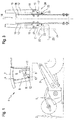
- Fig. 1 shows the front half of a combine harvester.
- the combine harvester carries at the front of its body a replaceable implement such as a grain cutter 1 for cutting and gathering crop material 2.
- a feederhouse 3 conveys the cut crop to a not-shown threshing mechanism inside the body.
- a cab 4 is mounted projecting on the body via the inclined conveyor 3.
- Large windows allow the driver from the cab 4 as unrestricted view of the grain cutter 1 or any other mounted on the combine implement.
- the windows comprise here a windshield 5, which extends continuously between the front edges of a bottom plate 6 and a roof 7 of the cab 4, and a door 8, which, apart from a narrow enclosing frame, completely through a plate made of safety glass or clear plastic is formed.
- the roof 7-bearing spar 9 On the spar 9 may also be provided for a lock of the door 8 a trap.
- a steering column 11 is placed centrally in front of a driver's seat 10, so find in a natural posture of the driver whose lower leg right and left of the steering column 11 place and his feet on either side of the steering column 11 can rest on the bottom plate 6.
- the footrests 12 may be directly attached to a front of the steering column 11; In the case shown here, a center column 13 between the steering column 11 and the windshield 5 is additionally provided as the support of the footrests 12.
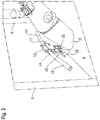
- Fig. 2 shows a section of the driver's cab, as seen through the door 8. It can be seen a part of the steering column 11 and arranged between the steering column 11 and a front edge of the bottom plate 6 center column 13, projecting from the two footrests 12 to the right and left in a position of use.
- the width of the center pillar 13 is adapted to that of the steering column 11, so that from the driver's perspective, the center pillar 13 is completely behind the steering column 11 supply. Only the footrests 12 Stand on both sides of the steering column 11, so that the driver can place his feet on it without obstruction by the steering column 11.
- the Fig. 3 shows in a view in the vehicle longitudinal direction of the combine a fitting part 14 with two pivotally mounted thereto footrests 12.
- the fitting part 14 is here a U-profile with the observer facing concave side, with a flat middle wall 15 and two from the edges of the central wall 15 in the direction of the viewer towards extending legs 16.
- the fitting 14 may be an integral part of the center column 13; Alternatively, the center column 13 or the steering column 11 may be provided on its side facing away from the driver's seat 10 with a vertically elongated rib on which the fitting 14 is attachable and to which it is screwed in different selectable heights to different heights of the footrests 12 on to realize the bottom plate 6.
- bearing parts 17 for the footrests 12 are attached on the legs 16, here in each case with the help of two screws.
- the bearing parts 17, like the fitting part 14, have a U-shaped cross-section with a center wall resting against one of the legs 16 and wings projecting at right angles from the middle wall and receiving two bolts with longitudinal axes 18, 19 in two bores each.
- the bolts can be secured in the holes of the bearing parts 17 each by pins.
- the longitudinal axis 18 of a bearing part 17 is in each case the pivot axis of one of the in Fig. 3
- the axis 19 is the pivot axis of a two-armed lever 20, the effect of which is based on Fig. 4 ff. will be explained in more detail later.
- One arm of the lever 20 is in Fig. 3 hidden inside the bearing part 17.
- a second arm of the lever 20 includes a leg 22 which extends from the journal 19 along the leg 16 of the fitting vertically downwards and is held by the leg 16 spread by a compression spring 23.
- a plate 24 is arranged which is extended in the vertical and in the vehicle longitudinal direction, so that the driver can comfortably hit it with a sideways movement of the foot and press against the center pillar 13, even without to be able to see him.
- the installation height of the fitting part 14 may be selected so that the plate 24 can be actuated by sideways pivoting of a foot resting on the base plate 6 with the heel.
- the plate 24 is replaced by a second leg 25, which extends from a lower end of the leg 22 sideways, away from the center column 13 extends.
- This leg 25 is preferably long enough to be visible from the perspective of the driver next to the steering column 11 or to be operable by extending a resting with the heel on the bottom plate 6 foot.
- levers 20 on the opposite side of the fitting part 14 could be mirror-inverted to the levers described above to be actuated in an analogous manner as described above from the right foot of the driver.
- both levers 20 are coupled to one another in order to rotate each other about their axis 19 when the left arm 21 is actuated in mirror image.
- a mechanism for coupling the two levers 20 may, for example, as in Fig. 2 shown hinged to the lower end of the legs 22 and be largely hidden in the center column 13.
- Fig. 4 shows a section perpendicular to the axes 18, 19 through the right bearing part 17 of Fig. 2 or 3 , a near-axis end of the right footrest 12 and the already mentioned, hidden in the bearing part 17 and here designated 26 arm of the lever 20th
- the footrest 12 is formed by a tube, for example with a cylindrical cross-section, in which case the axis 18 crosses the longitudinal axis of the tube and wall sections 27, 28 of the footrest 12 can be seen on either side of the axis 18. That in the Fig. 4 shown end of the footrest 12 is cut off obliquely, so that the wall portions 27, 28 in the position shown vary widely down and in particular facing away from the central column 13 wall portion 28 beyond the axis 18 and further than the opposite wall portion 27 extends down.
- a pivoting movement of the footrest 12 in a clockwise direction is blocked by a lower edge 29 of the wall section 27 being supported at the free end of the arm 26.
- the arm 26 can not yield to the pressure of the wall section 27, since a projection 30 of the lever 20 bearing against the center wall 31 of the bearing part 17 prevents it from pivoting counterclockwise.
- the pivoting movement ends when in the in Fig. 6 shown use position, the lower edge 29 of the wall portion 28 against a stop, here about the middle wall 31 of the bearing part 17, abuts.
- the driver can place his foot on the now upstanding wall portion 27, and the footrest 12 carries the weight of the foot.
- the length of the footrests 12 is dimensioned so that in the use position they protrude just far enough on both sides of the steering column 11 to allow comfortable placement of the feet on it, while at the same time avoiding restriction of the free view laterally from the feet resting thereon.
- the footrest 12 pivots upward in the direction of the waiting position.
- the lower edge 29 of the wall portion 28 initially strokes without touching on an upper side of the arm 26 along.
- the lower edge 29 finally abuts against a ramp 32 of the arm 26 and thus presses the arm 26 against the tension of the compression spring 23 downwards.
Landscapes
- Engineering & Computer Science (AREA)
- Transportation (AREA)
- Mechanical Engineering (AREA)
- Aviation & Aerospace Engineering (AREA)
- Harvester Elements (AREA)
- Body Structure For Vehicles (AREA)
Abstract
Description
- Die vorliegende Erfindung betrifft eine Fahrerkabine, insbesondere für eine landwirtschaftliche Arbeitsmaschine wie etwa einen Mähdrescher oder einen Feldhäcksler.
- Derartige Arbeitsmaschinen tragen im Allgemeinen an ihrer Vorderseite ein Arbeitsgerät wie etwa einen Erntevorsatz, der von der Fahrerkabine aus genau zu beobachten sein muss. Um dem Fahrer eine möglichst uneingeschränkte Sicht zu bieten, kann die Fahrerkabine der Arbeitsmaschine eine Frontscheibe aufweisen, die sich ununterbrochen zwischen einem Dach und einer Bodenplatte der Fahrerkabine sowie horizontal über deren gesamte Breite erstreckt und eventuell auch auf die seitlichen Flanken der Fahrerkabine ausgreift.
- Es ist an sich wünschenswert, in der Fahrerkabine einer landwirtschaftlichen Arbeitsmaschine Fußstützen vorzusehen, die es dem Fahrer ermöglichen, während der Arbeit seine Sitzhaltung zu wechseln. Aus
EP 2 873 557 B1 ist eine Fahrerkabine für eine Baumaschine bekannt, bei der Fußstützen an zwei sich beiderseits einer Frontscheibe erstreckenden vertikalen Holmen montiert sind und in eine Stellung schwenkbar sind, in der sie sich von den Holmen aus horizontal vor der Frontscheibe erstrecken. Je breiter die Frontscheibe ist, umso länger müssen die Fußstützen sein, um den Fahrer nicht zu einer unnötig gespreizten Beinhaltung zu zwingen. Je länger die Fußstützen sind, umso stärker beeinträchtigen sie auch die Sicht. Würde man, um kürzere Fußstützen verwenden zu können, die Breite der Frontscheibe verringern, dann würden die Holme zur Mitte des Blickfelds des Fahrers rücken und so die Sicht aus der Fahrerkabine beeinträchtigen. - Aufgabe der Erfindung ist es, eine Fahrerkabine zu schaffen, die dem Fahrer bequeme wechselnde Sitzhaltungen ermöglicht und dabei Einschränkungen der Sicht weitestgehend vermeidet.
- Die Aufgabe wird gelöst, indem bei einer Fahrerkabine für eine landwirtschaftliche Arbeitsmaschine an linker und rechter Seite einer Mittelsäule jeweils eine Fußstütze montiert ist, die zwischen einer Warteposition und einer Nutzungsposition schwenkbar ist. In der Nutzungsposition kann zwar unter Umständen nicht völlig vermieden werden, dass die Fußstützen für den Fahrer sichtbar sind und die Sicht durch eine Frontscheibe einschränken, doch da sie sich seitwärts nicht weiter erstrecken müssen, als zum Platzieren der Füße erforderlich, beeinträchtigen sie insbesondere nicht die für ein sicheres Navigieren der Arbeitsmaschine erforderliche freie Sicht auf den linken und rechten Rand eines an der Arbeitsmaschine montierten Arbeitsgeräts. Während die Fußstützen in der Nutzungsposition von der Mittelsäule jeweils seitwärts abgespreizt sein sollten, um die Füße des Fahrers stützen zu können, können sie durch Schwenken nur in eine Warteposition gelangen, in der sie enger als in der Nutzungsposition zur Mittelsäule benachbart sind und in der sie die Sicht somit noch weniger einschränken als in der Nutzungsposition.
- Die Fahrerkabine kann in an sich bekannter Weise eine Lenksäule aufweisen, die ein Lenkrad, einen Steuerknüppel oder ein anderes Instrument zum Steuern von Fahrtrichtung und/oder Geschwindigkeit der Arbeitsmaschine trägt. Eine solche Lenksäule blockiert unvermeidlicherweise einen Teil des Sichtfelds des Fahrers. Wenn die oben erwähnte Mittelsäule mit einer solchen Lenksäule identisch ist oder aus Fahrersicht mit der Lenksäule überlappt, kann die Einschränkung der freien Sicht durch die Mittelsäule weiter minimiert werden.
- Jede Fußstütze sollte eine Fußaufstellfläche aufweisen, die wenigstens in der Nutzungsposition weiter von der Mittelsäule entfernt ist als die Achse, um welche die Fußstütze schwenkbar ist. Vorzugsweise sind die Fußstützen um eine in Fahrzeuglängsrichtung orientierte Achse schwenkbar. So ist die Schwenkbewegung zwangsläufig auch mit einer Anhebung oder Absenkung der Fußstützen verbunden, und der Übergang zwischen Warteposition und Nutzungsposition kann in einer Richtung durch Schwerkraft angetrieben sein.
- Vorzugsweise sind die Fußstützen in Warteposition aus der Nutzungsposition angehoben, d.h. der durch Schwerkraft angetriebene Übergang ist der von der Warte- in die Nutzungsposition.
- Um die Fußstützen in der höhergelegenen der beiden Positionen, vorzugsweise also in der Warteposition, gegen einen unbeabsichtigten Übergang zu sichern, kann ein Rastmittel vorgesehen sein.
- Ein Betätigungselement zum Entrasten des Rastmittels kann an der Mittelsäule angeordnet sein. Vorzugsweise ist es unterhalb der Achse der Fußstütze platziert, sodass es bequem mit einem Fuß erreichbar und betätigbar ist.
- Einer bevorzugten Ausgestaltung zufolge bilden das Betätigungselement und das Rastmittel jeweils einen Arm eines zweiarmigen Hebels, wobei der das Betätigungselement bildende Arm wenigstens einen sich von einer Achse des Hebels entlang der Mittelsäule abwärts erstreckenden ersten Schenkel umfasst. Ein solcher Schenkel kann betätigt werden, indem er mit dem Fuß gegen die Mittelsäule gedrückt wird.
- Um das Betätigen des Schenkels zu erleichtern, auch wenn der Schenkel für den Fahrer nicht sichtbar und z.B. hinter der Lenksäule verborgen ist, kann das untere Ende des Schenkels tellerförmig verbreitert sein.
- Einer Weiterbildung zufolge ist das Betätigungselement gewinkelt und umfasst ferner einen zweiten Schenkel, der sich von einem unteren Ende des ersten Schenkels aus von der Mittelsäule fort erstreckt. Ein solcher Schenkel kann betätigt werden, indem er mit dem Fuß angehoben oder, vorzugsweise, heruntergedrückt wird.
- Zwischen dem ersten Schenkel und der Mittelsäule kann eine Druckfeder angebracht sein, um den ersten Schenkel, wenn das Betätigungselement nicht betätigt ist, von der Mittelsäule abgespreizt zu halten.
- Der als Rastmittel fungierende Hebelarm kann sich in Höhe der Achse von der Mittelsäule fort erstrecken.
- Um die die Fußstützen tragende Struktur einfach zu halten, sind die Achse des zweiarmigen Hebels und die Achse der Fußstütze vorzugsweise in einem gleichen Beschlagteil gelagert.
- Ein solches Beschlagteil kann an der Mittelsäule in unterschiedlichen Höhenlagen befestigbar sein, um dem Fahrer eine Anpassung der Höhe der Fußstütze an seine persönlichen Vorlieben zu ermöglichen.
- Um eine hohe Tragfähigkeit bei geringem Gewicht zu erreichen, kann die Fußstütze als ein Hohlkörper mit einem in der Nutzungsposition oberen, als Auflagefläche der Füße dienenden Wandabschnitt und einem in der Nutzungsposition unteren Wandabschnitt ausgebildet sein. Wenn dieser Hohlkörper ein offenes achsnahes Ende aufweist, kann dieses zur Verrastung der Fußstütze in der Warteposition genutzt werden, indem das Rastmittel in das offene Ende des Hohlkörpers eingreift.
- In der Warteposition, wenn die Fußstützte im Wesentlichen in die Vertikale geklappt ist, erstreckt sich der untere Wandabschnitt vorzugsweise abwärts über den oberen Wandabschnitt hinaus. So kann sichergestellt werden, dass eine Anschlagfläche, die den unteren Wandabschnitt der Nutzungsposition blockiert, nicht bereits vor Erreichen der Nutzungsposition mit dem oberen Wandabschnitt zusammenwirkt.
- Eine solche Anschlagfläche kann insbesondere mit einer Kante des unteren Wandabschnitts zusammenwirken.
- Weitere Merkmale und Vorteile der Erfindung ergeben sich aus der nachfolgenden Beschreibung von Ausführungsbeispielen unter Bezugnahme auf die beigefügten Figuren. Es zeigen:
- Fig. 1
- eine schematische, teilweise geschnittene Seitenansicht der vorderen Hälfte eines Mähdreschers als Beispiel für eine erfindungsgemäße Arbeitsmaschine;
- Fig. 2
- eine Innenansicht einer Fahrerkabine des Mähdreschers;
- Fig. 3
- eine Ansicht eines Beschlagteils mit zwei daran montierten Fußstützen;
- Fig. 4
- ein Detail der Verbindung zwischen Beschlagteilen und einer der Fußstützen in Warteposition im Schnitt;
- Fig. 5
- einen zur
Fig. 4 analogen Schnitt, der die Fußstütze in entrasteter Stellung auf dem Weg von der Warteposition in die Nutzungsposition zeigt; - Fig. 6
- einen Schnitt durch das Beschlagteil und die Fußstütze in der Nutzungsposition; und
- Fig. 7
- einen Schnitt durch das Beschlagteil und die Fußstütze auf dem Weg zurück in die Warteposition.
-
Fig. 1 zeigt die vordere Hälfte eines Mähdreschers. Der Mähdrescher trägt an der Vorderseite seiner Karosserie ein austauschbares Arbeitsgerät wie etwa ein Getreideschneidwerk 1 zum Schneiden und Sammeln von Erntegut 2. Ein Schrägförderer 3 befördert das geschnittene Erntegut zu einem nicht gezeigten, an sich bekannten Dreschwerk im Inneren der Karosserie. Eine Fahrerkabine 4 ist an der Karosserie über den Schrägförderer 3 vorspringend montiert. Große Fensterflächen gewähren dem Fahrer aus der Fahrerkabine 4 einen möglichst uneingeschränkten Blick auf das Getreideschneidwerk 1 oder ein beliebiges anderes am Mähdrescher montiertes Arbeitsgerät. Die Fensterflächen umfassen hier eine Frontscheibe 5, die sich ununterbrochen zwischen den Vorderkanten einer Bodenplatte 6 und eines Dachs 7 der Fahrerkabine 4 erstreckt, sowie eine Tür 8, die, eventuell abgesehen von einem schmalen einfassenden Rahmen, vollständig durch eine Platte aus Sicherheitsglas oder glasklarem Kunststoff gebildet ist. Zwischen der Frontscheibe 5 und der Tür 8 erstreckt sich ein schmaler, das Dach 7 tragender Holm 9. An dem Holm 9 kann ferner eine Falle für ein Schloss der Tür 8 vorgesehen sein. - In der Fahrerkabine 4 ist vor einem Fahrersitz 10 eine Lenksäule 11 mittig platziert, sodass in einer natürlichen Sitzhaltung des Fahrers dessen Unterschenkel rechts und links von der Lenksäule 11 Platz finden und seine Füße beiderseits der Lenksäule 11 auf der Bodenplatte 6 ruhen können.
- Um dem Fahrer neben der Haltung mit den Füßen auf der Bodenplatte 6 noch ein weitere bequeme Sitzhaltung anbieten zu können, sind an einer vom Fahrer abgewandten Seite der Lenksäule 11 nach rechts und links ausklappbare Fußstützen 12 montiert. Die Fußstützen 12 können unmittelbar an einer Vorderseite der Lenksäule 11 angebracht sein; in dem hier gezeigten Fall ist als Träger der Fußstützen 12 zusätzlich eine Mittelsäule 13 zwischen der Lenksäule 11 und der Frontscheibe 5 vorgesehen.
-
Fig. 2 zeigt einen Ausschnitt der Fahrerkabine, gesehen durch die Tür 8. Man erkennt einen Teil der Lenksäule 11 und die zwischen der Lenksäule 11 und einer Vorderkante der Bodenplatte 6 angeordnete Mittelsäule 13, von der in einer Nutzungsposition die zwei Fußstützen 12 nach rechts und links abstehen. - Die Breite der Mittelsäule 13 ist an die der Lenksäule 11 angepasst, sodass aus der Sicht des Fahrers die Mittelsäule 13 komplett hinter der Lenksäule 11 versorgen ist. Lediglich die Fußstützen 12 stehen beiderseits der Lenksäule 11 über, so dass der Fahrer seine Füße darauf ohne Behinderung durch die Lenksäule 11 platzieren kann.
- Die
Fig. 3 zeigt in einer Ansicht in Fahrzeuglängsrichtung des Mähdreschers ein Beschlagteil 14 mit zwei schwenkbar daran montierten Fußstützen 12. Das Beschlagteil 14 ist hier ein U-Profil mit dem Betrachter zugewandter konkaver Seite, mit einer ebenen Mittelwand 15 und zwei sich von den Kanten der Mittelwand 15 aus in Richtung zum Betrachter hin erstreckenden Schenkeln 16. Das Beschlagteil 14 kann fester Bestandteil der Mittelsäule 13 sein; alternativ können die Mittelsäule 13 oder die Lenksäule 11 an ihrer vom Fahrersitz 10 abgewandten Seite mit einer vertikal langgestreckten Rippe versehen sein, auf die das Beschlagteil 14 aufsteckbar ist und an der es in unterschiedlichen, wählbaren Höhen verschraubbar ist, um unterschiedliche Höhen der Fußstützen 12 über der Bodenplatte 6 zu realisieren. - An den Schenkeln 16 sind, hier jeweils mit Hilfe von zwei Schrauben, Lagerteile 17 für die Fußstützen 12 befestigt. Die Lagerteile 17 haben wie das Beschlagteil 14 einen U-förmigen Querschnitt mit einer Mittelwand, die an einem der Schenkel 16 anliegt, und von der Mittelwand rechtwinklig abstehenden Flügeln, die in je zwei Bohrungen zwei Bolzen mit Längsachsen 18, 19 aufnehmen. Wie in der
Fig. 3 angedeutet, können die Bolzen in den Bohrungen der Lagerteile 17 jeweils durch Splinte gesichert sein. - Die Längsachse 18 eines Lagerteils 17 ist jeweils die Schwenkachse einer der in
Fig. 3 in Wartestellung gezeigten Fußstützen 12. Die Achse 19 ist die Schwenkachse eines zweiarmigen Hebels 20, dessen Wirkung anhand vonFig. 4 ff. später genauer erläutert wird. Ein Arm des Hebels 20 ist inFig. 3 im Inneren des Lagerteils 17 verborgen. Ein zweiter Arm des Hebels 20 umfasst einen Schenkel 22, der sich vom Achszapfen 19 aus entlang des Schenkels 16 des Beschlagteils vertikal nach unten erstreckt und von dem Schenkel 16 durch eine Druckfeder 23 abgespreizt gehalten ist. - Am unteren Ende des Schenkels 22 ist einer ersten Ausgestaltung der Erfindung zufolge ein Teller 24 angeordnet, der in der Vertikalen und in der Fahrzeuglängsrichtung ausgedehnt ist, sodass der Fahrer ihn mit einer Seitwärtsbewegung des Fußes bequem treffen und gegen die Mittelsäule 13 drücken kann, auch ohne ihn dabei sehen zu können. Insbesondere kann die Einbauhöhe des Beschlagteils 14 so gewählt sein, dass der Teller 24 durch Seitwärtsschwenken eines mit der Ferse auf der Bodenplatte 6 ruhenden Fußes betätigbar ist.
- Einer zweiten Ausgestaltung zufolge und wie auch in
Fig. 2 gezeigt ist der Teller 24 durch einen zweiten Schenkel 25 ersetzt, der sich ausgehend von einem unteren Ende des Schenkels 22 seitwärts, von der Mittelsäule 13 fort, erstreckt. Dieser Schenkel 25 ist vorzugsweise lang genug, um aus der Perspektive des Fahrers neben der Lenksäule 11 sichtbar zu sein bzw. durch ein Ausstrecken eines mit der Ferse auf der Bodenplatte 6 ruhenden Fußes betätigbar zu sein. - Die Hebel 20 auf der gegenüberliegenden Seite des Beschlagteils 14 könnten spiegelbildlich zu den oben beschriebenen Hebeln ausgebildet sein, um in analoger Weise wie oben beschrieben vom rechten Fuß des Fahrers betätigt zu werden. Vorzugsweise sind jedoch beide Hebel 20 aneinander gekoppelt, um bei Betätigung des linken Arms 21 jeweils spiegelbildlich zueinander um ihre Achse 19 zu rotieren.
- Ein Mechanismus zum Koppeln der beiden Hebel 20 kann z.B., wie in
Fig. 2 gezeigt, an das untere Ende von deren Schenkeln 22 angelenkt und großenteils in der Mittelsäule 13 verborgen sein. -
Fig. 4 zeigt einen Schnitt senkrecht zu den Achsen 18, 19 durch das rechte Lagerteil 17 derFig. 2 oder3 , ein achsnahes Ende der rechten Fußstütze 12 und den bereits erwähnten, im Lagerteil 17 verborgenen und hier mit 26 bezeichneten Arm des Hebels 20. - Die Fußstütze 12 ist durch ein Rohr, zum Beispiel mit zylindrischem Querschnitt, gebildet, wobei hier die Achse 18 die Längsachse des Rohrs kreuzt und Wandabschnitte 27, 28 der Fußstütze 12 beiderseits der Achse 18 zu sehen sind. Das in der
Fig. 4 gezeigte Ende der Fußstütze 12 ist schräg abgeschnitten, sodass die Wandabschnitte 27, 28 in der gezeigten Stellung unterschiedlich weit nach unten reichen und insbesondere der von der Mittelsäule 13 abgewandte Wandabschnitt 28 über die Achse 18 hinaus und weiter als der gegenüberliegende Wandabschnitt 27 nach unten reicht. - Eine Schwenkbewegung der Fußstütze 12 im Uhrzeigersinn ist dadurch blockiert, dass eine untere Kante 29 des Wandabschnitts 27 sich am freien Ende des Arms 26 abstützt. Der Arm 26 kann dem Druck des Wandabschnitts 27 nicht nachgeben, da ein an der Mittelwand 31 des Lagerteils 17 anliegender Vorsprung 30 des Hebels 20 diesen an einem Schwenken entgegen dem Uhrzeigersinn hindert.
- Wenn der Fahrer, zum Beispiel durch Beiseitedrücken des Tellers 24 oder Herunterdrücken des Schenkels 25, den Hebel 20 der
Fig. 4 im Uhrzeigersinn schwenkt, dann geht, wie inFig. 5 gezeigt, die Überlappung zwischen dem freien Ende des Arms 26 und dem Wandabschnitt 28 verloren, und die Fußstütze 12 ist frei, um ihrem Eigengewicht folgend im Uhrzeigersinn in Richtung der Nutzungsposition zu schwenken. - Die Schwenkbewegung endet, wenn in der in
Fig. 6 gezeigten Nutzungsposition die untere Kante 29 des Wandabschnitts 28 gegen einen Anschlag, hier etwa die Mittelwand 31 des Lagerteils 17, anstößt. In dieser Stellung kann der Fahrer seinen Fuß auf dem nun oben liegenden Wandabschnitt 27 platzieren, und die Fußstütze 12 trägt das Gewicht des Fußes. Die Länge der Fußstützen 12 ist so bemessen, dass sie in der Nutzungsposition gerade weit genug beiderseits der Lenksäule 11 vorspringen, um eine bequeme Platzierung der Füße darauf zu ermöglichen, gleichzeitig aber eine Einschränkung der freien Sicht seitlich von den darauf ruhenden Füßen zu vermeiden. - Drückt der Fahrer in der Nutzungsposition jedoch mit dem Fuß von unten gegen den Wandabschnitt 28, so schwenkt die Fußstütze 12 aufwärts in Richtung der Warteposition. Wie in
Fig. 7 gezeigt, streicht dabei die untere Kante 29 des Wandabschnitts 28 zunächst ohne Berührung an einer Oberseite des Arms 26 entlang. Wenn die Schwenkbewegung fortgesetzt wird, stößt die untere Kante 29 schließlich gegen eine Rampe 32 des Arms 26 und drückt so den Arm 26 entgegen der Spannung der Druckfeder 23 abwärts. - Wenn die Kante 29 das Ende der Rampe 32 passiert hat, schwenkt die Druckfeder 23 den Hebel 20 zurück in die Stellung der
Fig. 4 , und die Fußstütze 12 ist von neuem in der Warteposition verrastet. -
- 1
- Getreideschneidwerk
- 2
- Erntegut
- 3
- Schrägförderer
- 4
- Fahrerkabine
- 5
- Frontscheibe
- 6
- Bodenplatte
- 7
- Dach
- 8
- Tür
- 9
- Säule
- 10
- Fahrersitz
- 11
- Lenksäule
- 12
- Fußstütze
- 13
- Mittelsäule
- 14
- Beschlagteil
- 15
- Mittelwand
- 16
- Schenkel
- 17
- Lagerteil
- 18
- Achse
- 19
- Achse
- 20
- Hebel
- 21
- Arm
- 22
- Schenkel
- 23
- Druckfeder
- 24
- Teller
- 25
- Schenkel
- 26
- Arm
- 27
- Wandabschnitt
- 28
- Wandabschnitt
- 29
- untere Kante
- 30
- Vorsprung
- 31
- Mittelwand
- 32
- Rampe
- 33
- (Kopplungs-)Mechanismus
Claims (15)
- Fahrerkabine für eine landwirtschaftliche Arbeitsmaschine, dadurch gekennzeichnet, dass an linker und rechter Seite einer Mittelsäule (13) jeweils eine Fußstütze (12) montiert ist, die zwischen einer Warteposition und einer Nutzungsposition um eine Achse (18) schwenkbar ist.
- Fahrerkabine nach Anspruch 1, dadurch gekennzeichnet, dass die Mittelsäule (13) mit einer Lenksäule (11) identisch ist oder aus Fahrersicht mit der Lenksäule (13) überlappt.
- Fahrerkabine nach Anspruch 1 oder 2, dadurch gekennzeichnet, dass jede Fußstütze (12) eine Fußaufstellfläche aufweist, die wenigstens in der Nutzungsposition weiter von der Mittelsäule (13) entfernt ist als ihre Achse (18).
- Fahrerkabine nach einem der vorhergehenden Ansprüche, dadurch gekennzeichnet, dass die Achse (18), um die die Fußstützen (12) schwenkbar sind, in Fahrzeuglängsrichtung orientiert ist.
- Fahrerkabine nach einem der vorhergehenden Ansprüche, dadurch gekennzeichnet, dass die Fußstützen (12) in der Warteposition aus der Nutzungsposition angehoben sind.
- Fahrerkabine nach einem der vorhergehenden Ansprüche, gekennzeichnet durch ein Rastmittel zum Verrasten einer der Fußstützen (12) in der Warteposition.
- Fahrerkabine nach Anspruch 6, dadurch gekennzeichnet, dass ein Betätigungselement zum Entrasten des Rastmittels an der Mittelsäule (13) unterhalb der Achsen (18) angeordnet ist.
- Fahrerkabine nach Anspruch 7, dadurch gekennzeichnet, dass das Betätigungselement und das Rastmittel jeweils einen Arm (21, 26) eines zweiarmigen Hebels (20) bilden, wobei das Betätigungselement einen sich von einer Achse (19) entlang der Mittelsäule (13) abwärts erstreckenden ersten Schenkel (22) umfasst.
- Fahrerkabine nach Anspruch 8, dadurch gekennzeichnet, dass das Betätigungselement gewinkelt ist und einen von einem unteren Ende des ersten Schenkels (22) aus von der Mittelsäule (13) fort erstreckenden zweiten Schenkel (25) umfasst.
- Fahrerkabine nach Anspruch 8 oder 9, dadurch gekennzeichnet, dass eine Druckfeder (23) zwischen dem ersten Schenkel (22) und der Mittelsäule (13) angebracht ist.
- Fahrerkabine nach Anspruch 8, 9 oder 10, dadurch gekennzeichnet, dass das Rastmittel sich in Höhe der Achse (19) von der Mittelsäule (13) fort erstreckt.
- Fahrerkabine nach einem der Ansprüche 8 bis 11, dadurch gekennzeichnet, dass die Achse (19) des zweiarmigen Hebels (20) und die Achse (18) der Fußstütze (12) an einem gleichen Beschlagteil (14) gelagert sind.
- Fahrerkabine nach einem der Ansprüche 6 bis 12, dadurch gekennzeichnet, dass die Fußstütze (12) ein Hohlkörper mit einem in der Nutzungsposition oberen Wandabschnitt (27) und einem in der Nutzungsposition unteren Wandabschnitt (28) ist und dass das Rastmittel in der Warteposition in ein offenes achsnahes Ende des Hohlkörpers eingreift.
- Fahrerkabine nach Anspruch 13, dadurch gekennzeichnet, dass in der Warteposition der untere Wandabschnitt (28) sich weiter als der obere Wandabschnitt (27) abwärts erstreckt.
- Fahrerkabine nach Anspruch 13 oder 14, dadurch gekennzeichnet, dass in der Nutzungsposition eine Kante (29) des unteren Wandabschnitts (28) mit einem Anschlag zusammenwirkt.
Applications Claiming Priority (1)
| Application Number | Priority Date | Filing Date | Title |
|---|---|---|---|
| DE102018001267.1A DE102018001267A1 (de) | 2018-02-19 | 2018-02-19 | Fahrerkabine |
Publications (2)
| Publication Number | Publication Date |
|---|---|
| EP3530552A1 true EP3530552A1 (de) | 2019-08-28 |
| EP3530552B1 EP3530552B1 (de) | 2021-07-28 |
Family
ID=64664680
Family Applications (1)
| Application Number | Title | Priority Date | Filing Date |
|---|---|---|---|
| EP18211611.1A Active EP3530552B1 (de) | 2018-02-19 | 2018-12-11 | Fahrerkabine |
Country Status (2)
| Country | Link |
|---|---|
| EP (1) | EP3530552B1 (de) |
| DE (1) | DE102018001267A1 (de) |
Families Citing this family (1)
| Publication number | Priority date | Publication date | Assignee | Title |
|---|---|---|---|---|
| DE102024104934A1 (de) * | 2024-02-22 | 2025-08-28 | Liebherr-Werk Nenzing Gmbh | Kabinenelement, Kabine und Arbeitsmaschine |
Citations (3)
| Publication number | Priority date | Publication date | Assignee | Title |
|---|---|---|---|---|
| US20140049029A1 (en) * | 2012-08-16 | 2014-02-20 | Cnh America Llc | Steering column for a work vehicle with integral adjustable foot rests |
| DE102014204638A1 (de) * | 2014-03-13 | 2015-09-17 | Bayerische Motoren Werke Aktiengesellschaft | Modulares Fußrastenbaukastensystem |
| EP2873557B1 (de) | 2012-07-12 | 2017-05-10 | Volvo Construction Equipment AB | Fussstütze für betriebsraum einer baumaschine |
-
2018
- 2018-02-19 DE DE102018001267.1A patent/DE102018001267A1/de not_active Withdrawn
- 2018-12-11 EP EP18211611.1A patent/EP3530552B1/de active Active
Patent Citations (3)
| Publication number | Priority date | Publication date | Assignee | Title |
|---|---|---|---|---|
| EP2873557B1 (de) | 2012-07-12 | 2017-05-10 | Volvo Construction Equipment AB | Fussstütze für betriebsraum einer baumaschine |
| US20140049029A1 (en) * | 2012-08-16 | 2014-02-20 | Cnh America Llc | Steering column for a work vehicle with integral adjustable foot rests |
| DE102014204638A1 (de) * | 2014-03-13 | 2015-09-17 | Bayerische Motoren Werke Aktiengesellschaft | Modulares Fußrastenbaukastensystem |
Also Published As
| Publication number | Publication date |
|---|---|
| DE102018001267A1 (de) | 2019-08-22 |
| EP3530552B1 (de) | 2021-07-28 |
Similar Documents
| Publication | Publication Date | Title |
|---|---|---|
| EP2190396B1 (de) | Aufrichtrollstuhl | |
| EP0215142B1 (de) | Halmteiler für landwirtschaftliche Maschinen | |
| EP2263909B1 (de) | Sitz | |
| EP0054948A1 (de) | Fahrerstand | |
| DE102020134877B4 (de) | Höhenverstellbarer Steuerhebelträger für einen Nutzfahrzeugsitz | |
| EP0159562A2 (de) | Aufrichtstuhl | |
| DE3227975A1 (de) | Selbstfahrender maehdrescher | |
| DE1283458B (de) | Sessel mit einer ein- und ausfahrbaren Beinstuetze | |
| EP1449711A2 (de) | Klappbarer Fahrzeugsitz | |
| DE102017009248A1 (de) | Kleinfertiger, Bedienplattforrn für einen Kleinfertiger und Verfahren | |
| DE3711001A1 (de) | Ablage fuer kraftfahrzeuge, insbesondere im tunnelbereich eines lastkraftwagens zwischen fahrer- und beifahrersitz | |
| DE202007016357U1 (de) | Kraftfahrzeugsitz | |
| EP1291232B1 (de) | Sitzgestell eines Kraftfahrzeugsitzes mit einem Sitzträger und vorderen Parallelogrammarmen | |
| EP4482358B1 (de) | Motorisierter funktionsbeschlag für ein bettgestell eines boxspringbetts oder eines plattformbetts oder für einen gerahmten lattenrost | |
| DE3619944A1 (de) | Der rueckenlehne eines kraftfahrzeugsitzes zugeordnete armlehne | |
| EP1632152A2 (de) | Sitzmöbel | |
| EP0518169A1 (de) | Höheneinstellvorrichtung für ein Mähwerksgehäuse | |
| EP3530552B1 (de) | Fahrerkabine | |
| DE2001840A1 (de) | Fernseh- (TV-) und voellig zurueckkippbarer Lehnstuhl bzw. Sessel und Beschlagteile fuer seinen Gelenk- und Kippmechanismus | |
| DE4113828C2 (de) | Fahrzeug zum Mähen | |
| DE2117665A1 (de) | Selbstfahrende Mähvorrichtung | |
| DE2049282C3 (de) | Patientenstuhl | |
| EP0372232B1 (de) | Stuhl, insbesondere Arbeits- oder Bürostuhl | |
| DE2028612A1 (de) | Aufhangung für einen Fahrzeugsitz | |
| DE69803513T2 (de) | Mähdrescherleiter mit Schwenkgelenkzapfen |
Legal Events
| Date | Code | Title | Description |
|---|---|---|---|
| PUAI | Public reference made under article 153(3) epc to a published international application that has entered the european phase |
Free format text: ORIGINAL CODE: 0009012 |
|
| STAA | Information on the status of an ep patent application or granted ep patent |
Free format text: STATUS: THE APPLICATION HAS BEEN PUBLISHED |
|
| AK | Designated contracting states |
Kind code of ref document: A1 Designated state(s): AL AT BE BG CH CY CZ DE DK EE ES FI FR GB GR HR HU IE IS IT LI LT LU LV MC MK MT NL NO PL PT RO RS SE SI SK SM TR |
|
| AX | Request for extension of the european patent |
Extension state: BA ME |
|
| STAA | Information on the status of an ep patent application or granted ep patent |
Free format text: STATUS: REQUEST FOR EXAMINATION WAS MADE |
|
| 17P | Request for examination filed |
Effective date: 20200228 |
|
| RBV | Designated contracting states (corrected) |
Designated state(s): AL AT BE BG CH CY CZ DE DK EE ES FI FR GB GR HR HU IE IS IT LI LT LU LV MC MK MT NL NO PL PT RO RS SE SI SK SM TR |
|
| GRAP | Despatch of communication of intention to grant a patent |
Free format text: ORIGINAL CODE: EPIDOSNIGR1 |
|
| STAA | Information on the status of an ep patent application or granted ep patent |
Free format text: STATUS: GRANT OF PATENT IS INTENDED |
|
| RIC1 | Information provided on ipc code assigned before grant |
Ipc: B62D 33/06 20060101AFI20210205BHEP Ipc: B60N 3/06 20060101ALI20210205BHEP Ipc: B60N 2/24 20060101ALI20210205BHEP Ipc: B60N 2/38 20060101ALI20210205BHEP |
|
| INTG | Intention to grant announced |
Effective date: 20210309 |
|
| GRAS | Grant fee paid |
Free format text: ORIGINAL CODE: EPIDOSNIGR3 |
|
| GRAA | (expected) grant |
Free format text: ORIGINAL CODE: 0009210 |
|
| STAA | Information on the status of an ep patent application or granted ep patent |
Free format text: STATUS: THE PATENT HAS BEEN GRANTED |
|
| AK | Designated contracting states |
Kind code of ref document: B1 Designated state(s): AL AT BE BG CH CY CZ DE DK EE ES FI FR GB GR HR HU IE IS IT LI LT LU LV MC MK MT NL NO PL PT RO RS SE SI SK SM TR |
|
| REG | Reference to a national code |
Ref country code: GB Ref legal event code: FG4D Free format text: NOT ENGLISH |
|
| REG | Reference to a national code |
Ref country code: CH Ref legal event code: EP |
|
| REG | Reference to a national code |
Ref country code: AT Ref legal event code: REF Ref document number: 1414518 Country of ref document: AT Kind code of ref document: T Effective date: 20210815 |
|
| REG | Reference to a national code |
Ref country code: IE Ref legal event code: FG4D Free format text: LANGUAGE OF EP DOCUMENT: GERMAN |
|
| REG | Reference to a national code |
Ref country code: DE Ref legal event code: R096 Ref document number: 502018006296 Country of ref document: DE |
|
| REG | Reference to a national code |
Ref country code: LT Ref legal event code: MG9D |
|
| REG | Reference to a national code |
Ref country code: NL Ref legal event code: MP Effective date: 20210728 |
|
| PG25 | Lapsed in a contracting state [announced via postgrant information from national office to epo] |
Ref country code: RS Free format text: LAPSE BECAUSE OF FAILURE TO SUBMIT A TRANSLATION OF THE DESCRIPTION OR TO PAY THE FEE WITHIN THE PRESCRIBED TIME-LIMIT Effective date: 20210728 Ref country code: SE Free format text: LAPSE BECAUSE OF FAILURE TO SUBMIT A TRANSLATION OF THE DESCRIPTION OR TO PAY THE FEE WITHIN THE PRESCRIBED TIME-LIMIT Effective date: 20210728 Ref country code: HR Free format text: LAPSE BECAUSE OF FAILURE TO SUBMIT A TRANSLATION OF THE DESCRIPTION OR TO PAY THE FEE WITHIN THE PRESCRIBED TIME-LIMIT Effective date: 20210728 Ref country code: ES Free format text: LAPSE BECAUSE OF FAILURE TO SUBMIT A TRANSLATION OF THE DESCRIPTION OR TO PAY THE FEE WITHIN THE PRESCRIBED TIME-LIMIT Effective date: 20210728 Ref country code: FI Free format text: LAPSE BECAUSE OF FAILURE TO SUBMIT A TRANSLATION OF THE DESCRIPTION OR TO PAY THE FEE WITHIN THE PRESCRIBED TIME-LIMIT Effective date: 20210728 Ref country code: NO Free format text: LAPSE BECAUSE OF FAILURE TO SUBMIT A TRANSLATION OF THE DESCRIPTION OR TO PAY THE FEE WITHIN THE PRESCRIBED TIME-LIMIT Effective date: 20211028 Ref country code: PT Free format text: LAPSE BECAUSE OF FAILURE TO SUBMIT A TRANSLATION OF THE DESCRIPTION OR TO PAY THE FEE WITHIN THE PRESCRIBED TIME-LIMIT Effective date: 20211129 Ref country code: NL Free format text: LAPSE BECAUSE OF FAILURE TO SUBMIT A TRANSLATION OF THE DESCRIPTION OR TO PAY THE FEE WITHIN THE PRESCRIBED TIME-LIMIT Effective date: 20210728 Ref country code: LT Free format text: LAPSE BECAUSE OF FAILURE TO SUBMIT A TRANSLATION OF THE DESCRIPTION OR TO PAY THE FEE WITHIN THE PRESCRIBED TIME-LIMIT Effective date: 20210728 Ref country code: BG Free format text: LAPSE BECAUSE OF FAILURE TO SUBMIT A TRANSLATION OF THE DESCRIPTION OR TO PAY THE FEE WITHIN THE PRESCRIBED TIME-LIMIT Effective date: 20211028 |
|
| PG25 | Lapsed in a contracting state [announced via postgrant information from national office to epo] |
Ref country code: PL Free format text: LAPSE BECAUSE OF FAILURE TO SUBMIT A TRANSLATION OF THE DESCRIPTION OR TO PAY THE FEE WITHIN THE PRESCRIBED TIME-LIMIT Effective date: 20210728 Ref country code: LV Free format text: LAPSE BECAUSE OF FAILURE TO SUBMIT A TRANSLATION OF THE DESCRIPTION OR TO PAY THE FEE WITHIN THE PRESCRIBED TIME-LIMIT Effective date: 20210728 Ref country code: GR Free format text: LAPSE BECAUSE OF FAILURE TO SUBMIT A TRANSLATION OF THE DESCRIPTION OR TO PAY THE FEE WITHIN THE PRESCRIBED TIME-LIMIT Effective date: 20211029 |
|
| PG25 | Lapsed in a contracting state [announced via postgrant information from national office to epo] |
Ref country code: DK Free format text: LAPSE BECAUSE OF FAILURE TO SUBMIT A TRANSLATION OF THE DESCRIPTION OR TO PAY THE FEE WITHIN THE PRESCRIBED TIME-LIMIT Effective date: 20210728 |
|
| REG | Reference to a national code |
Ref country code: DE Ref legal event code: R097 Ref document number: 502018006296 Country of ref document: DE |
|
| PG25 | Lapsed in a contracting state [announced via postgrant information from national office to epo] |
Ref country code: SM Free format text: LAPSE BECAUSE OF FAILURE TO SUBMIT A TRANSLATION OF THE DESCRIPTION OR TO PAY THE FEE WITHIN THE PRESCRIBED TIME-LIMIT Effective date: 20210728 Ref country code: SK Free format text: LAPSE BECAUSE OF FAILURE TO SUBMIT A TRANSLATION OF THE DESCRIPTION OR TO PAY THE FEE WITHIN THE PRESCRIBED TIME-LIMIT Effective date: 20210728 Ref country code: RO Free format text: LAPSE BECAUSE OF FAILURE TO SUBMIT A TRANSLATION OF THE DESCRIPTION OR TO PAY THE FEE WITHIN THE PRESCRIBED TIME-LIMIT Effective date: 20210728 Ref country code: EE Free format text: LAPSE BECAUSE OF FAILURE TO SUBMIT A TRANSLATION OF THE DESCRIPTION OR TO PAY THE FEE WITHIN THE PRESCRIBED TIME-LIMIT Effective date: 20210728 Ref country code: CZ Free format text: LAPSE BECAUSE OF FAILURE TO SUBMIT A TRANSLATION OF THE DESCRIPTION OR TO PAY THE FEE WITHIN THE PRESCRIBED TIME-LIMIT Effective date: 20210728 Ref country code: AL Free format text: LAPSE BECAUSE OF FAILURE TO SUBMIT A TRANSLATION OF THE DESCRIPTION OR TO PAY THE FEE WITHIN THE PRESCRIBED TIME-LIMIT Effective date: 20210728 |
|
| PLBE | No opposition filed within time limit |
Free format text: ORIGINAL CODE: 0009261 |
|
| STAA | Information on the status of an ep patent application or granted ep patent |
Free format text: STATUS: NO OPPOSITION FILED WITHIN TIME LIMIT |
|
| 26N | No opposition filed |
Effective date: 20220429 |
|
| PG25 | Lapsed in a contracting state [announced via postgrant information from national office to epo] |
Ref country code: MC Free format text: LAPSE BECAUSE OF FAILURE TO SUBMIT A TRANSLATION OF THE DESCRIPTION OR TO PAY THE FEE WITHIN THE PRESCRIBED TIME-LIMIT Effective date: 20210728 Ref country code: IT Free format text: LAPSE BECAUSE OF FAILURE TO SUBMIT A TRANSLATION OF THE DESCRIPTION OR TO PAY THE FEE WITHIN THE PRESCRIBED TIME-LIMIT Effective date: 20210728 |
|
| REG | Reference to a national code |
Ref country code: CH Ref legal event code: PL |
|
| PG25 | Lapsed in a contracting state [announced via postgrant information from national office to epo] |
Ref country code: LU Free format text: LAPSE BECAUSE OF NON-PAYMENT OF DUE FEES Effective date: 20211211 Ref country code: IE Free format text: LAPSE BECAUSE OF NON-PAYMENT OF DUE FEES Effective date: 20211211 |
|
| PG25 | Lapsed in a contracting state [announced via postgrant information from national office to epo] |
Ref country code: FR Free format text: LAPSE BECAUSE OF NON-PAYMENT OF DUE FEES Effective date: 20211231 |
|
| PG25 | Lapsed in a contracting state [announced via postgrant information from national office to epo] |
Ref country code: LI Free format text: LAPSE BECAUSE OF NON-PAYMENT OF DUE FEES Effective date: 20211231 Ref country code: CH Free format text: LAPSE BECAUSE OF NON-PAYMENT OF DUE FEES Effective date: 20211231 |
|
| P01 | Opt-out of the competence of the unified patent court (upc) registered |
Effective date: 20230516 |
|
| PG25 | Lapsed in a contracting state [announced via postgrant information from national office to epo] |
Ref country code: CY Free format text: LAPSE BECAUSE OF FAILURE TO SUBMIT A TRANSLATION OF THE DESCRIPTION OR TO PAY THE FEE WITHIN THE PRESCRIBED TIME-LIMIT Effective date: 20210728 |
|
| PG25 | Lapsed in a contracting state [announced via postgrant information from national office to epo] |
Ref country code: HU Free format text: LAPSE BECAUSE OF FAILURE TO SUBMIT A TRANSLATION OF THE DESCRIPTION OR TO PAY THE FEE WITHIN THE PRESCRIBED TIME-LIMIT; INVALID AB INITIO Effective date: 20181211 |
|
| GBPC | Gb: european patent ceased through non-payment of renewal fee |
Effective date: 20221211 |
|
| PG25 | Lapsed in a contracting state [announced via postgrant information from national office to epo] |
Ref country code: GB Free format text: LAPSE BECAUSE OF NON-PAYMENT OF DUE FEES Effective date: 20221211 |
|
| PG25 | Lapsed in a contracting state [announced via postgrant information from national office to epo] |
Ref country code: MK Free format text: LAPSE BECAUSE OF FAILURE TO SUBMIT A TRANSLATION OF THE DESCRIPTION OR TO PAY THE FEE WITHIN THE PRESCRIBED TIME-LIMIT Effective date: 20210728 |
|
| PG25 | Lapsed in a contracting state [announced via postgrant information from national office to epo] |
Ref country code: TR Free format text: LAPSE BECAUSE OF FAILURE TO SUBMIT A TRANSLATION OF THE DESCRIPTION OR TO PAY THE FEE WITHIN THE PRESCRIBED TIME-LIMIT Effective date: 20210728 |
|
| PG25 | Lapsed in a contracting state [announced via postgrant information from national office to epo] |
Ref country code: MT Free format text: LAPSE BECAUSE OF FAILURE TO SUBMIT A TRANSLATION OF THE DESCRIPTION OR TO PAY THE FEE WITHIN THE PRESCRIBED TIME-LIMIT Effective date: 20210728 |
|
| REG | Reference to a national code |
Ref country code: AT Ref legal event code: MM01 Ref document number: 1414518 Country of ref document: AT Kind code of ref document: T Effective date: 20231211 |
|
| PG25 | Lapsed in a contracting state [announced via postgrant information from national office to epo] |
Ref country code: AT Free format text: LAPSE BECAUSE OF NON-PAYMENT OF DUE FEES Effective date: 20231211 |
|
| PGFP | Annual fee paid to national office [announced via postgrant information from national office to epo] |
Ref country code: DE Payment date: 20251211 Year of fee payment: 8 |
|
| PGFP | Annual fee paid to national office [announced via postgrant information from national office to epo] |
Ref country code: BE Payment date: 20251219 Year of fee payment: 8 |
|
| PGFP | Annual fee paid to national office [announced via postgrant information from national office to epo] |
Ref country code: AT Payment date: 20260410 Year of fee payment: 5 |