EP3530492A1 - Air supply system for a work vehicle - Google Patents
Air supply system for a work vehicle Download PDFInfo
- Publication number
- EP3530492A1 EP3530492A1 EP19153980.8A EP19153980A EP3530492A1 EP 3530492 A1 EP3530492 A1 EP 3530492A1 EP 19153980 A EP19153980 A EP 19153980A EP 3530492 A1 EP3530492 A1 EP 3530492A1
- Authority
- EP
- European Patent Office
- Prior art keywords
- air
- tire
- air supply
- pressure
- work vehicle
- Prior art date
- Legal status (The legal status is an assumption and is not a legal conclusion. Google has not performed a legal analysis and makes no representation as to the accuracy of the status listed.)
- Granted
Links
Images


Classifications
-
- B—PERFORMING OPERATIONS; TRANSPORTING
- B60—VEHICLES IN GENERAL
- B60C—VEHICLE TYRES; TYRE INFLATION; TYRE CHANGING; CONNECTING VALVES TO INFLATABLE ELASTIC BODIES IN GENERAL; DEVICES OR ARRANGEMENTS RELATED TO TYRES
- B60C23/00—Devices for measuring, signalling, controlling, or distributing tyre pressure or temperature, specially adapted for mounting on vehicles; Arrangement of tyre inflating devices on vehicles, e.g. of pumps or of tanks; Tyre cooling arrangements
- B60C23/001—Devices for manually or automatically controlling or distributing tyre pressure whilst the vehicle is moving
- B60C23/003—Devices for manually or automatically controlling or distributing tyre pressure whilst the vehicle is moving comprising rotational joints between vehicle-mounted pressure sources and the tyres
- B60C23/00354—Details of valves
-
- B—PERFORMING OPERATIONS; TRANSPORTING
- B60—VEHICLES IN GENERAL
- B60C—VEHICLE TYRES; TYRE INFLATION; TYRE CHANGING; CONNECTING VALVES TO INFLATABLE ELASTIC BODIES IN GENERAL; DEVICES OR ARRANGEMENTS RELATED TO TYRES
- B60C23/00—Devices for measuring, signalling, controlling, or distributing tyre pressure or temperature, specially adapted for mounting on vehicles; Arrangement of tyre inflating devices on vehicles, e.g. of pumps or of tanks; Tyre cooling arrangements
- B60C23/001—Devices for manually or automatically controlling or distributing tyre pressure whilst the vehicle is moving
- B60C23/003—Devices for manually or automatically controlling or distributing tyre pressure whilst the vehicle is moving comprising rotational joints between vehicle-mounted pressure sources and the tyres
- B60C23/00372—Devices for manually or automatically controlling or distributing tyre pressure whilst the vehicle is moving comprising rotational joints between vehicle-mounted pressure sources and the tyres characterised by fluid diagrams
-
- B—PERFORMING OPERATIONS; TRANSPORTING
- B60—VEHICLES IN GENERAL
- B60C—VEHICLE TYRES; TYRE INFLATION; TYRE CHANGING; CONNECTING VALVES TO INFLATABLE ELASTIC BODIES IN GENERAL; DEVICES OR ARRANGEMENTS RELATED TO TYRES
- B60C23/00—Devices for measuring, signalling, controlling, or distributing tyre pressure or temperature, specially adapted for mounting on vehicles; Arrangement of tyre inflating devices on vehicles, e.g. of pumps or of tanks; Tyre cooling arrangements
- B60C23/10—Arrangement of tyre-inflating pumps mounted on vehicles
-
- B—PERFORMING OPERATIONS; TRANSPORTING
- B60—VEHICLES IN GENERAL
- B60T—VEHICLE BRAKE CONTROL SYSTEMS OR PARTS THEREOF; BRAKE CONTROL SYSTEMS OR PARTS THEREOF, IN GENERAL; ARRANGEMENT OF BRAKING ELEMENTS ON VEHICLES IN GENERAL; PORTABLE DEVICES FOR PREVENTING UNWANTED MOVEMENT OF VEHICLES; VEHICLE MODIFICATIONS TO FACILITATE COOLING OF BRAKES
- B60T13/00—Transmitting braking action from initiating means to ultimate brake actuator with power assistance or drive; Brake systems incorporating such transmitting means, e.g. air-pressure brake systems
- B60T13/10—Transmitting braking action from initiating means to ultimate brake actuator with power assistance or drive; Brake systems incorporating such transmitting means, e.g. air-pressure brake systems with fluid assistance, drive, or release
- B60T13/24—Transmitting braking action from initiating means to ultimate brake actuator with power assistance or drive; Brake systems incorporating such transmitting means, e.g. air-pressure brake systems with fluid assistance, drive, or release the fluid being gaseous
- B60T13/26—Compressed-air systems
-
- B—PERFORMING OPERATIONS; TRANSPORTING
- B60—VEHICLES IN GENERAL
- B60T—VEHICLE BRAKE CONTROL SYSTEMS OR PARTS THEREOF; BRAKE CONTROL SYSTEMS OR PARTS THEREOF, IN GENERAL; ARRANGEMENT OF BRAKING ELEMENTS ON VEHICLES IN GENERAL; PORTABLE DEVICES FOR PREVENTING UNWANTED MOVEMENT OF VEHICLES; VEHICLE MODIFICATIONS TO FACILITATE COOLING OF BRAKES
- B60T13/00—Transmitting braking action from initiating means to ultimate brake actuator with power assistance or drive; Brake systems incorporating such transmitting means, e.g. air-pressure brake systems
- B60T13/10—Transmitting braking action from initiating means to ultimate brake actuator with power assistance or drive; Brake systems incorporating such transmitting means, e.g. air-pressure brake systems with fluid assistance, drive, or release
- B60T13/58—Combined or convertible systems
-
- B—PERFORMING OPERATIONS; TRANSPORTING
- B60—VEHICLES IN GENERAL
- B60T—VEHICLE BRAKE CONTROL SYSTEMS OR PARTS THEREOF; BRAKE CONTROL SYSTEMS OR PARTS THEREOF, IN GENERAL; ARRANGEMENT OF BRAKING ELEMENTS ON VEHICLES IN GENERAL; PORTABLE DEVICES FOR PREVENTING UNWANTED MOVEMENT OF VEHICLES; VEHICLE MODIFICATIONS TO FACILITATE COOLING OF BRAKES
- B60T17/00—Component parts, details, or accessories of power brake systems not covered by groups B60T8/00, B60T13/00 or B60T15/00, or presenting other characteristic features
- B60T17/02—Arrangements of pumps or compressors, or control devices therefor
-
- F—MECHANICAL ENGINEERING; LIGHTING; HEATING; WEAPONS; BLASTING
- F04—POSITIVE - DISPLACEMENT MACHINES FOR LIQUIDS; PUMPS FOR LIQUIDS OR ELASTIC FLUIDS
- F04B—POSITIVE-DISPLACEMENT MACHINES FOR LIQUIDS; PUMPS
- F04B43/00—Machines, pumps, or pumping installations having flexible working members
-
- B—PERFORMING OPERATIONS; TRANSPORTING
- B60—VEHICLES IN GENERAL
- B60T—VEHICLE BRAKE CONTROL SYSTEMS OR PARTS THEREOF; BRAKE CONTROL SYSTEMS OR PARTS THEREOF, IN GENERAL; ARRANGEMENT OF BRAKING ELEMENTS ON VEHICLES IN GENERAL; PORTABLE DEVICES FOR PREVENTING UNWANTED MOVEMENT OF VEHICLES; VEHICLE MODIFICATIONS TO FACILITATE COOLING OF BRAKES
- B60T17/00—Component parts, details, or accessories of power brake systems not covered by groups B60T8/00, B60T13/00 or B60T15/00, or presenting other characteristic features
- B60T17/002—Air treatment devices
- B60T17/004—Draining and drying devices
-
- B—PERFORMING OPERATIONS; TRANSPORTING
- B60—VEHICLES IN GENERAL
- B60T—VEHICLE BRAKE CONTROL SYSTEMS OR PARTS THEREOF; BRAKE CONTROL SYSTEMS OR PARTS THEREOF, IN GENERAL; ARRANGEMENT OF BRAKING ELEMENTS ON VEHICLES IN GENERAL; PORTABLE DEVICES FOR PREVENTING UNWANTED MOVEMENT OF VEHICLES; VEHICLE MODIFICATIONS TO FACILITATE COOLING OF BRAKES
- B60T2260/00—Interaction of vehicle brake system with other systems
- B60T2260/08—Coordination of integrated systems
Definitions
- the present disclosure relates generally to an air system for a work vehicle.
- Certain work vehicles are configured to operate on a variety of terrains. For example, work vehicles may be operated on roads. While the work vehicle is operating on a road, a greater tire pressure may be desired to improve efficiency and to reduce wear on the tires. Work vehicles may also be operated in fields. While the work vehicle is operating in a field, a lower tire pressure may be desired to improve traction and to decrease pressure on the ground. Additionally, certain work vehicles are configured to tow and/or carry varied loads. Some work vehicles include a tire inflation system that may facilitate inflation and deflation of the tires of the work vehicle (e.g., during operation of the work vehicle) by utilizing a compressor of the work vehicle.
- the air pressure within the tires of the work vehicle may be adjusted based on the expected terrain.
- tire inflation systems may be limited by the output of the compressor of the work vehicle.
- the work vehicle may include large tires and the use of the compressor of the work vehicle to increase the air pressure within the tires may take a long time, thereby delaying agricultural operation. Further, operating the compressor of the work vehicle may use a large amount of fuel.
- an air supply system for a work vehicle includes a compressor configured to compress a first supply of ambient air and to output a compressed air supply via a compressed air line, an air induction assembly configured to receive the compressed air supply from the compressed air line and to flow the compressed air supply through a body of the air induction assembly to create a low pressure region sufficient to draw in a second supply of ambient air, wherein the body is configured to combine the second supply of ambient air with the compressed air supply to generate a combination air supply, and a tire inflation system fluidly coupled to the air induction assembly and configured to selectively increase and decrease an air pressure within a tire of the work vehicle.
- an air supply system for a work vehicle includes a compressor configured to compress a first supply of ambient air and to output a compressed air supply via a compressed air line, an air induction assembly configured to receive the compressed air supply from the compressed air line and to flow the compressed air supply through a body of the air induction assembly to create a low pressure region sufficient to draw in a second supply of ambient air, wherein the body is configured to combine the second supply of ambient air with the compressed air supply to generate a combination air supply, wherein a total mass flow rate of the combination air supply comprises a sum of a mass flow rate of the compressed air supply and a mass flow rate of the second supply of ambient air, a tire inflation system fluidly coupled to the air induction assembly and configured to selectively increase and decrease an air pressure within a tire of the work vehicle, wherein the tire inflation system includes a pressure valve and a distribution line, wherein the pressure valve is disposed along the distribution line and configured to control the increase and decrease of the air pressure within the tire, a priority valve disposed between the air induction
- an air intake system for a work vehicle includes a compressor configured to compress a first supply of ambient air and output a compressed air supply via a compressed air line, and an air induction assembly configured to receive the compressed air supply from the compressed air line and to flow the compressed air supply through the air induction assembly to create a low pressure region sufficient to draw in a second supply of ambient air, wherein the body is configured to combine the second supply of ambient air with the compressed air supply to generate a combination air supply for use by a tire inflation system of the work vehicle, wherein the air induction assembly comprises a body, and wherein the body includes an input region, a constricted region, and a output region, or an orifice plate disposed within the body.
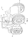
- FIG. 1 is a perspective view of an embodiment of a work vehicle 10 that includes an air supply system 12.
- the work vehicle 10 includes a body 14 configured to house an engine, a transmission, the air supply system 12, other systems of the work vehicle 10, or a combination thereof.
- the work vehicle 10 includes a cab 16 configured to house an operator.
- the work vehicle 10 includes tires 18 (e.g., mounted on wheels), including front tires and back tires, configured to be driven by a drive system coupled to the engine and/or the transmission, thereby driving the work vehicle 10 along a field, a road, or any other suitable surface.
- the operator may steer the work vehicle 10 by manipulating or providing an input to a hand controller 20 within the cab 16.
- the hand controller 20 is a steering wheel.
- the work vehicle 10 may be steered by any suitable controlling device, such as an electronic controlling device located within the work vehicle 10 or remote from the work vehicle 10. Additionally, the operator may slow or stop the work vehicle 10 by manipulating or providing an input to a brake pedal 22.
- the work vehicle 10 may be configured to be remotely controlled and/or to operate autonomously. While the illustrated work vehicle 10 is a tractor, it should be appreciated that the air supply system 12 described herein may be employed within any other suitable work vehicle, such as a truck, an automobile, a harvester, a sprayer, or a skid steer. As discussed in detail below, the air supply system 12 of the work vehicle 10 may control inflation, or inflation pressure, of each of the tires 18 of the work vehicle 10.
- the air supply system 12 may include a tire inflation system, which may provide air to the individual tires 18 of the work vehicle 10. Further, the air supply system 12 may provide air to a pneumatic brake system of the work vehicle 10.
- the air supply system 12 includes an air induction assembly configured to passively draw ambient air into the air supply system 12 of the work vehicle 10. The air drawn into the air supply system 12 via the air induction assembly may be combined with a compressed air supply provided by a compressor, thereby increasing the volumetric flow rate of air within the air supply system 12 and, in turn, decreasing inflation time of a tire, as compared to only output of the compressor.
- a controller of the work vehicle 10 may be configured to control distribution of the air from the air supply system to the tire inflation system and to the pneumatic brake system of the work vehicle 10, as well as to control distribution of the air to the individual tires 18 of the work vehicle 10.
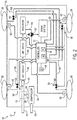
- FIG. 2 is a schematic diagram of an embodiment of an air supply system 12 having a tire inflation system 30 that may be employed within the work vehicle 10 of FIG. 1 .
- the air supply system 12 may include the tire inflation system 30, which may supply air to the tires 18 of the work vehicle 10.
- the air supply system 12 may also supply air to a pneumatic brake system 32 of the work vehicle 10.
- the air supply system 12 includes a compressor 34.
- the compressor 34 may be driven by the engine of the work vehicle (e.g., and controlled by a clutch positioned between the engine and the compressor). In some embodiments, the compressor 34 may be water cooled.
- the compressor 34 may receive ambient air 36 at atmospheric pressure, compress the air, and output compressed air at a higher pressure and a lower volume.
- the compressed air may then be used to pressurize the brakes of the pneumatic brake system 32 and/or to increase tire pressure via the tire inflation system 30.
- the compressor 34 may output the compressed air 38 via a compressed air line 39.
- the compressed air line 39 may include a check valve that may block the compressed air 38 output from the compressor 34 from flowing back toward the compressor 34.
- the air supply system 12 includes an air induction assembly 40.
- the air induction assembly 40 (e.g., air amplifier) receives the compressed air 38 from the compressed air line 39 and uses the compressed air 38 to draw in ambient air 42.
- the air induction assembly 40 may include any suitable type of assembly configured to draw in ambient air using the compressed air, such as a venturi assembly, examples of which are discussed in greater detail with reference to FIGS. 3-5 .
- the flow of the compressed air 38 through the air induction assembly 40 may passively draw the ambient air 42 by creating a low pressure area at the air induction assembly 40.
- the ambient air 42 drawn into the air induction assembly 40 may aggregate with the compressed air 38 from the compressed air line 39 to create a combination air flow 44 within a line 45 that may direct the combination air 44 into an air cooler 46.
- the air induction assembly 40 may increase the volumetric flow rate of air into the air supply system 12 (e.g., as compared to only output of the compressor), which may in turn decrease inflation time of the individual tires 18 via the tire inflation system 30.
- the line 45 may deliver the combination air 44 from the air induction assembly 40 to the air cooler 46 (e.g. radiator).
- Compressing the ambient air 36 via the compressor 34 may increase the temperature of the compressed air 38 output from the compressor 34 into the compressed air line 39.
- the temperature of the air when it is compressed may increase, for example, to around 250° C.
- the combination air 44 from the line 45 output from the air induction assembly 40 may be directed through the air cooler 46.
- the air cooler 46 may include any suitable type of cooling assembly or heat exchanger.
- the air cooler 46 may be a radiator which cools the combination air 44 via heat exchange between coolant and/or ambient air and the combination air 44. This in turn reduces the temperature of the combination air 44.
- the induction of the ambient air 42 into the air induction assembly 40 may help cool the combination air 44 before entering the air cooler 46.
- the combination air 44 from the air induction assembly 40 in the line 45 may have a lower temperature than the compressed air 38 in the compressed air line 39 because the ambient air 42 may cool the compressed air 38 to establish a lower temperature combination air 44. Therefore, the induction of the ambient air 42 into the air induction assembly 40 may reduce the air temperature in the line 45 entering the air cooler 46 (e.g., as compared to only air output from the compressor) and, thus, may reduce the load on the air cooler 46. In some embodiments, the temperature reduction provided by the induction of the ambient air 42 into the air induction assembly 40 may be sufficient to obviate the air cooler 46 from the air supply system 12.
- the combination air 44 may be delivered to an air dryer 48 of the air supply system 12.
- the process of air compression within the compressor 34 may also concentrate any water vapor present, which may lead to condensation within the lines of the air supply system 12 as the combination air 44 cools downstream of the compressor 34, for example at the air cooler 46.
- the air dryer 48 e.g., compressed air dryer
- the air dryer 48 may remove water vapor from the combination air 44.
- the air dryer 48 may remove moisture to substantially reduce or eliminate condensation from occurring within the air supply system 12.
- the combination air 44 may be delivered to a reservoir 50.
- the reservoir 50 may store the combination air 44 for use by the tire inflation system 30 and the pneumatic brake system 32.
- the air supply system 12 includes a controller 52 that may be used to control distribution and delivery of the combination air 44.
- the controller 52 may control distribution and delivery of the combination air 44 between the pneumatic brake system 32 and the tire inflation system 30, as well as between individual tires 18 of the work vehicle 10.
- the controller 52 includes a memory 54 and a processor 56.
- the memory 54 may include one or more tangible, non-transitory, computer-readable media that store instructions executable by the processor 56 and/or data to be processed by the processor 56.
- the memory 54 may include access memory (RAM), read only memory (ROM), rewritable non-volatile memory such as flash memory, hard drives, optical discs, and/or the like.
- the processor 56 may include one or more general purpose microprocessors, one or more application specific processors (ASICs), one or more field programmable logic arrays (FPGAs), or any combination thereof.
- the air supply system 12 may further include a user interface 58 or input/output (I/O) devices that may facilitate communication between the controller 52 and a user (e.g., operator).
- the user interface 58 may be disposed within the cab of the work vehicle 10 or at a remote location in the case of a remotely controlled or autonomously operated work vehicle 10.
- the user interface 58 may include a button, a keyboard, a mouse, a trackpad, and/or the like to enable user interaction with the controller 52.
- the user interface 58 may include an electronic display to facilitate providing a visual representation of information, for example, via a graphical user interface (GUI), an application interface, text, a still image, and/or video content.
- GUI graphical user interface
- the controller 52 may receive various input signals from sensors throughout the air supply system 12 and/or other components of the work vehicle 10 at the processor 56.
- these input signals and/or control signals (e.g., instruction signals) output by the controller 52 may be stored in the memory 54.
- the input signals may be utilized individually or in various combinations to determine current usage of the combination air 44 within the air supply system 12 and current tire pressure of the individual tires 18 of the work vehicle 10.
- the controller 52 may further receive input signals from the user (e.g., operator) via the user interface 58 indicative of a target pressure of each tire 18 of the work vehicle 10. Additionally, the controller 52 may receive input signals indicative of current usage of the pneumatic brake system 32.
- the controller 52 may then output various instruction signals to valves and/or actuators of the air supply system 12 to control deliver of the combination air 44 to the tire inflation system 30 and to individual tires 18 of the work vehicle 10 to achieve a target pressure within each tire 18.
- the user interface 58 may send signals indicative of the target pressure of each tire 18 to the controller 52 based on input from the operator (e.g., based at least in part on a particular terrain on which the work vehicle is currently driving on and/or a load being towed by the work vehicle 10).
- the controller 52 may receive one or more signals indicative of the current measured pressure of each tire 18 of the work vehicle 10 via pressure sensors 60.
- the pressure sensors 60 may be disposed at each tire 18 of the work vehicle and measure the current pressure within each tire 18.
- Each pressure sensor 60 may send signal(s) indicative of the current pressure within a respective tire 18 to the controller 52.
- the controller 52 may output one or more signals to the user interface 58 indicative of the measured tire pressure of each tire 18 of the work vehicle 10. Via the user interface 58, the operator positioned within the cab 16 of the work vehicle 10 or positioned remotely may view the measured tire pressure within each tire 18.
- the operator may input to the controller 52, via the user interface 58, the target pressure for each tire 18 of the work vehicle 10.
- the controller 52 may determine the target pressure of each tire 18 of the work vehicle 10 based at least in part on input signals (e.g., from the user interface 58, from load sensors, from terrain sensors, etc.) indicative of the terrain and/or or the load being towed. Based on the received or determined target pressure of each tire 18 of the work vehicle, the controller 52 may compare the current pressure of each tire 18 to the target pressure of each tire 18 and may determine whether to inflate or deflate each individual tire 18 such that the tire pressure corresponds to the target pressure.
- the air supply system 12 may supply the combination air 44 to the tire inflation system 30 and to the pneumatic brake system 32.
- the controller 52 may give priority to the pneumatic brake system 32, such that the controller 52 causes the combination air 44 from the reservoir 50 to be distributed first to the pneumatic brake system 32 for use in generating a braking force to slow or stop the work vehicle 10.
- the controller 52 may cause the combination air 44 to be distributed to the tire inflation system 30 for use in varying the pressure within the tires 18 of the work vehicle 10.
- the air supply system 12 includes a valve 62 disposed along a line 64 (e.g., pipe) extending from the reservoir 50 to the pneumatic brake system 32 and to the tire inflation system 30.
- the valve 62 may be a priority valve, three way valve, or other suitable valve that may give priority distribution of the combination air 44 from the reservoir 50 to the pneumatic brake system 32 over the tire inflation system 30. That is, the controller 52 may output a control signal to an actuator of the valve 62 indicative of instructions to open the valve 62 to a position such that the combination air 44 is distributed only to the pneumatic brake system 32 when an input to slow or stop the work vehicle 10 is received.
- the controller 52 may receive a signal indicative of a request to slow or stop the work vehicle 10 directly from the brake pedal of the work vehicle 10 or from the pneumatic brake system 32 indicative of current usage of the pneumatic brake system 32. Therefore, when the pneumatic brake system 32 is in use, the valve 62 may enable the combination air 44 to be supplied to the pneumatic brake system 32 and disable the combination air 44 to the tire inflation system 30.
- the controller 52 may instruct distribution of the combination air 44 to the tire inflation system 30 for use in varying the pressure of the tires 18 to correspond to the input or determined target pressure. As such, the controller 52 may determine that the pneumatic brake system 32 is not currently in use (e.g., based on a signal received from the pneumatic brake system 32 indicative of the pneumatic brake system 32 not currently being in use, a lack of input signal from the brake pedal indicative of a request to slow or stop the work vehicle 10, or a lack of input signal from the pneumatic brake system 32 indicative of current use of the pneumatic brake system 32).
- the controller 52 may, upon receiving an input signal indicative of the target pressure of the tires 18, control the valve 62 to enable the combination air 44 from the reservoir 50 to be distributed to the tire inflation system 30 to inflate the tires 18.
- the controller 52 may instruct adjustment of the pressure within each tire 18 of the work vehicle individually.
- the air supply system 12 includes several valves 66 disposed along distribution lines 68 that are configured to direct the combination air 44 to each individual tire 18. There may be one valve 66 disposed along each distribution line 68 to control air flow to and from the corresponding tire 18 to increase or decrease the pressure within the tire 18.
- the air supply system may include only one valve 66 that controls air flow to all tires 18 or several valves 66 that control air flow to groups of tires 18.
- the controller 52 may compare the current measured pressure of each tire 18 to the target pressure.
- the controller 52 may determine the current pressure of each tire 18 based on signals received from pressure sensors 60 disposed at the tires 18 indicative of the current measured pressure within each tire 18. If the controller 52 determines that the current measured pressure of an individual tire 18 does not correspond to the target pressure, the controller 52 may send a control signal to the corresponding valve 66 to open to increase or decrease the pressure within the tire 18 based on the comparison until the current pressure of the tire 18 reaches the target pressure. Thus, the controller 52 may cause the air pressure within each tire 18 to correspond to the target pressure.
- the controller 52 may cause air to be released from the tire 18 regardless of whether the pneumatic brake system 32 is currently in use, as availability of the combination air 44 from the air supply system 12 may not be utilized to release pressure from the tires 18.
- the target pressure of the tires 18 may be lower than the current pressure of the tires 18.
- the lower tire pressure may enable greater tire contact with the ground, improve traction, increase fuel efficiency, and/or reduce ground pressure on the roots of the plants in the field.
- the controller 52 may receive one or more input signals (e.g., from the operator of the work vehicle 10 via the user interface 58) indicative of the target pressure, the terrain, the towed load, or a combination thereof.
- input signals received from the user interface 58 may be indicative of a request to increase or decrease the pressure of one or more individual tires 18 of the work vehicle.
- the controller 52 may also receive signals from the pressure sensors 60 associated with the tires 18 indicative of the current measured pressure of each tire 18.
- the controller 52 may compare the current measured pressure of each tire 18 to the received or determined target pressure (e.g., determined based on the terrain, the towed load, etc.). If the controller 52 determines that the current pressure of a tire 18 is greater than the target pressure, the controller 52 may output signal(s) to the valve 66 associated with the tire 18 indicative of an instruction to open the valve 66 such that air is released from the tire 18 until the pressure of the tire 18 substantially corresponds to the target pressure (e.g., until the difference between the measured tire pressure and the target pressure is less than a threshold value).
- This process may be repeated for each tire, or the tire pressure for all or some of the tires may be adjusted concurrently.
- Signals from the pressure sensors 60 associated with the tires 18 indicative of the measured pressures may provide feedback to the controller 52 such that the controller 52 may determine when the target pressure is reached within each tire 18.
- the controller 52 may output instruction signals to the close the corresponding valves 66.
- the target pressure of the tires 18 may be greater that the current pressure of the tires 18.
- the higher tire pressure may improve fuel efficiency, improve wear on the tires 18, and/or improve the ride of the work vehicle.
- the controller 52 may receive one or more input signals (e.g., from the operator of the work vehicle 10 via the user interface 58) indicative of the target pressure, the terrain, the towed load, or a combination thereof.
- input signals received from the user interface 58 may be indicative of a request to increase or decrease the pressure of one or more individual tires 18 of the work vehicle.
- the controller 52 may also receive signals from the pressure sensors 60 associated with the tires 18 indicative of the current measured pressure of each tire 18.
- the controller 52 may compare the current measured pressure of each tire 18 to the received or determined target pressure (e.g., determined based on the terrain, the towed load, etc.). If the controller 52 determines that the current pressure of a tire 18 is lower than the target pressure, the controller 52 may then determine whether the combination air 44 is currently being used by the pneumatic brake system 32 to slow or stop the work vehicle 10, as previously discussed.
- the target pressure e.g., determined based on the terrain, the towed load, etc.
- the controller 52 may output a signal to the valve 62 disposed along the line 64 extending from the reservoir 50 to the pneumatic brake system 32 and to the tire inflation system 30 indicative of an instruction to control the valve 62 such that the combination air 44 is distributed to the tire inflation system 30.
- the controller 52 may also output one or more control signals to the valves 66 along the distribution lines 68 to control the valves 66 such that the combination air 44 is delivered to the corresponding tires 18 to increase the pressure within the tires 18 to substantially correspond to the target pressure(s). This process may be repeated for each tire 18 or the tire pressure may be adjusted for all or some of the tires 18 concurrently.
- signals from the pressure sensors 60 associated with the tires 18 indicative of the measured pressures may provide feedback to the controller 52 such that the controller 52 may determine when the target pressure is reached within each tire 18.
- the controller 52 may output instruction signals to the control the corresponding valves 66 to close.
- the air supply system 12 includes an air induction assembly 40 configured to draw additional ambient air into the air supply system 12 to increase the total volumetric flow rate of air that may be used to control the pressure(s) of the tires 18 of the work vehicle 10.
- the air induction assembly 40 may be any suitable type of assembly configured to draw in ambient air.
- FIGS. 3-5 may be used as the air induction assembly 40 of FIG. 2 .
- FIG. 3 is a cross-sectional view of an embodiment of an air induction assembly 78 that may be employed within the air supply system of FIG. 2 .
- the air induction assembly 78 includes a venturi assembly 80, and a portion of the compressed air line 39 carrying the compressed air 38 output from the compressor 34 is positioned within the venturi assembly 80.
- the venturi assembly 80 includes a constricted section 82 between two wider sections (e.g., wider in diameter), an input section 84 and an output section 86.
- the input section 84 and the output section 86 each have a larger flow area that the constricted section 82.
- the input section 84 may join the constricted section 82 via a converging section 85 and the constricted section 82 may join the output section 86 via a diverging section 87.
- the wider output section 86 of the venturi assembly 80 may be the input of the line 45 that distributes the combination air 44 to the air cooler.
- a curved portion 88 of the compressed air line 39 is disposed within the constricted section 82 of the venturi assembly 80 such that an outlet 89 of the compressed air line 39 is disposed within the constricted section 82 and configured to direct the compressed air 38 toward the wider output region 86.
- the flow of the compressed air 38 from the constricted section 82, where it enters the venturi assembly 80 via the outlet 89 of the compressed air line 39, to the wider output section 86 establishes a lower pressure in the compressed section 82 as compared to the wider input section 84.
- Lower pressure at the constricted section 82 causes in the ambient air 42 from outside of the work vehicle 10 to be drawn into the venturi assembly 80.
- the ambient air 42 then combines with the compressed air 38 output from the compressor 34, resulting in an increase of the total volumetric air flow rate in the air supply system 12.
- the total mass flow rate of the combination air 44 is the sum of the mass flow rate of the compressed air 38 output from the compressor 34 and the mass flow rate of the ambient air 42 drawn in via the air induction assembly 78.
- the increased total volumetric air flow rate of the combination air 44 may provide reduced fill times for inflation of the tires 18 of the work vehicle 10 to the target pressure, as compared to utilizing only the output of the compressor. Additionally, as previously discussed, the addition of the ambient air 42 to the compressed air 38 may reduce the temperature of the combination air 44, thus reducing, and in some embodiments eliminating, the load on the air cooler of the air supply system.
- the wider input section 84 and the wider output section 86 of the venturi assembly 80 may have the same or different flow areas.
- ratios of the flow area of the constricted section 82 to the flow area of the input section 84 and the output section 86 may be the same or different.
- the ratio of the flow area (e.g., expansion/contraction ratio) of the constricted section 82 to the flow area of the input section 84 and/or the output section 86 may be any suitable ratio (e.g., 1:2, 1:3, 1:4) configured to draw in ambient air 42 to increase the volumetric flow rate within the air supply system.
- a ratio of the flow area of the outlet 89 of the compressed air line 39 to the flow area of the constricted section 82 within which the outlet 89 is disposed may be any suitable ratio (e.g., 1:2, 1:3, 1:4) configured to create a low pressure region as the compressed air 38 moves from the compressed air line 39 to the constricted section 82 and to the output section 86.
- the curved portion 88 of the compressed air line 39 opening to the outlet 89 is disposed within the constricted section 82 of the venturi assembly 80.
- the portion of the compressed air line 39 approaching the outlet 89 may not be curved.
- the outlet 89 of the compressed air line 39 is illustrated as a sufficiently straight outlet, however, in some embodiments, the outlet 89 may converge or diverge.
- the converging section 85 and the diverging section 87 connecting the wider input and output sections 84, 86 and the constricted section 82 have straight walls.
- the walls of the converging section 85 and/or the diverging section 87 may be rounded or have any other suitable arrangement.
- FIG. 4 is a cross-sectional view of another embodiment of an air induction assembly 90 that may be employed within the air supply system of FIG. 2 .
- the air induction assembly 90 includes a venturi assembly 80.
- the compressed air line 39 carrying the compressed air 38 output from the compressor 34 extends to the venturi assembly 80 such that the compressed air 38 flows through a side 92 of the constricted section 82.
- the venturi assembly 80 includes a constricted section 82 between two wider sections (e.g., wider in diameter), an input section 84 and an output section 86.
- the input section 84 and the output section 86 each have a larger flow area that the constricted section 82.
- the input section 84 may join the constricted section 82 via a converging section 85 and the constricted section 82 may join the output section 86 via a diverging section 87.
- the wider output section 86 of the venturi assembly 80 may be the input of the line 45 that distributes the combination air 44 to the air cooler.
- the flow of the compressed air 38 from the constricted section 82, where it enters the venturi assembly 80 through the side 92 via the outlet 89 of the compressed air line 39, to the wider output section 86 establishes a lower pressure in the compressed section 82 as compared to the wider input section 84.
- Lower pressure at the constricted section 82 causes in the ambient air 42 from outside of the work vehicle 10 to be drawn into the venturi assembly 80.
- the ambient air 42 then combines with the compressed air 38 output from the compressor 34, resulting in an increase of the total volumetric air flow rate in the air supply system 12.
- the total mass flow rate of the combination air 44 is the sum of the mass flow rate of the compressed air 38 output from the compressor 34 and the mass flow rate of the ambient air 42 drawn in via the air induction assembly 90.
- the wider input section 84 and the wider output section 86 of the venturi assembly 80 may have the same or different flow areas.
- ratios of the flow area of the constricted section 82 to the flow area of the input section 84 and the output section 86 may be the same or different.
- the ratio of the flow area (e.g., expansion/contraction ratio) of the constricted section 82 to the flow area of the input section 84 and/or the output section 86 may be any suitable ratio (e.g., 1:2, 1:3, 1:4) configured to draw in ambient air 42 to increase the volumetric flow rate within the air supply system.
- a ratio of the flow area of the outlet 89 of the compressed air line 39 to the flow area of the constricted section 82 may be any suitable ratio (e.g., 1:2, 1:3, 1:4) configured to create a low pressure region as the compressed air 38 moves from the compressed air line 39 to the constricted section 82 and to the output section 86.
- the outlet 89 of the compressed air line 39 is illustrated as a sufficiently straight outlet, however, in some embodiments, the outlet 89 may converge or diverge.
- the converging section 85 and the diverging section 87 connecting the wider input and output sections 84, 86 and the constricted section 82 have straight walls. In other embodiments, the walls of the converging section 85 and/or the diverging section 87 may be rounded or have any other suitable arrangement.
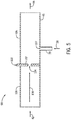
- FIG. 5 is a cross-sectional view of a further embodiment of an air induction assembly 98 that may be employed within the air supply system of FIG. 2 .
- the air induction assembly 98 includes an orifice plate 100 that is used to create a low pressure region that may draw in the ambient air 42.
- the orifice plate may be a disk 102 of metal or other suitable material with an orifice 104 (e.g., opening).
- the orifice plate 100 is positioned within a body 106 of the air induction assembly 98 upstream of an outlet 107 of the compressed air line 39 relative to a direction 108 of flow of the ambient air 42.
- the flow of the compressed air 38 into the body 106 of the air induction assembly 98 to the line 45 establishes a lower pressure at the orifice 104 of the orifice plate as compared to the body 106 of the air induction assembly 98 upstream of the orifice plate 100 relative to the direction 108.
- Lower pressure at the orifice plate 100 causes the ambient air 42 from outside of the work vehicle 10 to be drawn into the air induction assembly 98.
- the ambient air 42 then combines with the compressed air 38 output from the compressor 34, resulting in an increase of the total volumetric air flow rate in the air supply system 12.
- the total mass flow rate of the combination air 44 is the sum of the mass flow rate of the compressed air 38 output from the compressor 34 and the mass flow rate of the ambient air 42 drawn in via the air induction assembly 98. Therefore, the air induction assembly 98 having the orifice plate 100 may increase the total volumetric air flow rate within the air supply system 12, which may result in reduced fill times for reaching the target pressure of the tires 18, as compared to utilizing only the output of the compressor. Further, the ambient air 42 may reduce the temperature of the compressed air 38, thus reducing the load on the air cooler of the air supply system 12.
- a ratio of the flow area of the orifice 104 of the orifice plate 100 to the flow area of the body 106 of the of the air induction assembly 98 may be any suitable ration (e.g., 1:2, 1:3, 1:4) configured to draw in ambient air 42 to increase the volumetric flow rate within the air supply system.
- the body 106 of the air induction assembly 98 has a tube shape, however, in some embodiments, the body 106 may include converging and/or diverging section(s).
- outlet 107 of the compressed air line 39 is shown in the illustrated embodiment at a particular distance downstream of the orifice plate 100 relative to the direction 108 of flow of the ambient air 42, the distance between the orifice plate 100 and the outlet 107 may be any suitable distance configured to enable the flow of the compressed air 38 to create a lower pressure at the orifice plate 100.
- the air induction assemblies 78, 90, and 98 may each be employed within the air supply system of FIG. 2 to draw in ambient air to increase the volumetric flow rate of air in the air supply system that may be used to increase and/or decrease the air pressure within the tires of the work vehicle.
- the air supply system including the tire inflation system and the air induction assembly may enable individualized control of the pressure within each tire of the work vehicle (e.g., based on the terrain and/or a load being pulled by the work vehicle). Such control of the pressure of the tires may increase fuel efficiency of the work vehicle, improve wear on the tires of the work vehicle, improve traction of the tires on varying terrains, improve plant growth by reducing ground pressure when in a field, improve the ride of the work vehicle, and/or improve towing efficiency when towing varied loads. Further, the air induction assembly may draw additional ambient air into air supply system. Thus, the air induction assembly may increase the total volumetric air flow rate supplied by the air supply system to the tires, which may in turn, decrease fill time of the tires.
- the air induction assembly may enable a reduction in the temperature of the air within the air supply system as the ambient air drawn in by the air induction assembly has a lower temperature than the air output from the compressor.
- the air induction assembly may reduce the load on the air cooler of the air supply system, and in some embodiments, may eliminate the air cooler, which may reduce costs.
Landscapes
- Engineering & Computer Science (AREA)
- Mechanical Engineering (AREA)
- Transportation (AREA)
- General Engineering & Computer Science (AREA)
- Valves And Accessory Devices For Braking Systems (AREA)
- Tires In General (AREA)
- Automobile Manufacture Line, Endless Track Vehicle, Trailer (AREA)
Abstract
Description
- The present disclosure relates generally to an air system for a work vehicle.
- Certain work vehicles (e.g., tractors, harvesters, skid steers, etc.) are configured to operate on a variety of terrains. For example, work vehicles may be operated on roads. While the work vehicle is operating on a road, a greater tire pressure may be desired to improve efficiency and to reduce wear on the tires. Work vehicles may also be operated in fields. While the work vehicle is operating in a field, a lower tire pressure may be desired to improve traction and to decrease pressure on the ground. Additionally, certain work vehicles are configured to tow and/or carry varied loads. Some work vehicles include a tire inflation system that may facilitate inflation and deflation of the tires of the work vehicle (e.g., during operation of the work vehicle) by utilizing a compressor of the work vehicle. Thus, the air pressure within the tires of the work vehicle may be adjusted based on the expected terrain. However, such tire inflation systems may be limited by the output of the compressor of the work vehicle. For example, the work vehicle may include large tires and the use of the compressor of the work vehicle to increase the air pressure within the tires may take a long time, thereby delaying agricultural operation. Further, operating the compressor of the work vehicle may use a large amount of fuel.
- In one embodiment, an air supply system for a work vehicle includes a compressor configured to compress a first supply of ambient air and to output a compressed air supply via a compressed air line, an air induction assembly configured to receive the compressed air supply from the compressed air line and to flow the compressed air supply through a body of the air induction assembly to create a low pressure region sufficient to draw in a second supply of ambient air, wherein the body is configured to combine the second supply of ambient air with the compressed air supply to generate a combination air supply, and a tire inflation system fluidly coupled to the air induction assembly and configured to selectively increase and decrease an air pressure within a tire of the work vehicle.
- In another embodiment, an air supply system for a work vehicle, includes a compressor configured to compress a first supply of ambient air and to output a compressed air supply via a compressed air line, an air induction assembly configured to receive the compressed air supply from the compressed air line and to flow the compressed air supply through a body of the air induction assembly to create a low pressure region sufficient to draw in a second supply of ambient air, wherein the body is configured to combine the second supply of ambient air with the compressed air supply to generate a combination air supply, wherein a total mass flow rate of the combination air supply comprises a sum of a mass flow rate of the compressed air supply and a mass flow rate of the second supply of ambient air, a tire inflation system fluidly coupled to the air induction assembly and configured to selectively increase and decrease an air pressure within a tire of the work vehicle, wherein the tire inflation system includes a pressure valve and a distribution line, wherein the pressure valve is disposed along the distribution line and configured to control the increase and decrease of the air pressure within the tire, a priority valve disposed between the air induction assembly and the tire inflation system, and a controller having a memory and a processor, wherein the controller is communicatively coupled to the priority valve and configured to control distribution of the combination air supply from the air induction assembly between the tire inflation system of the work vehicle and a brake system of the work vehicle.
- In another embodiment, an air intake system for a work vehicle includes a compressor configured to compress a first supply of ambient air and output a compressed air supply via a compressed air line, and an air induction assembly configured to receive the compressed air supply from the compressed air line and to flow the compressed air supply through the air induction assembly to create a low pressure region sufficient to draw in a second supply of ambient air, wherein the body is configured to combine the second supply of ambient air with the compressed air supply to generate a combination air supply for use by a tire inflation system of the work vehicle, wherein the air induction assembly comprises a body, and wherein the body includes an input region, a constricted region, and a output region, or an orifice plate disposed within the body.
- These and other features, aspects, and advantages of the present disclosure will become better understood when the following detailed description is read with reference to the accompanying drawings in which like characters represent like parts throughout the drawings, wherein:
-
FIG. 1 is a perspective view of an embodiment of a work vehicle that includes an air supply system; -
FIG. 2 is a schematic diagram of an embodiment of an air supply system having a tire inflation system that may be employed within the work vehicle ofFIG. 1 ; -
FIG. 3 is a cross-sectional view of an embodiment of an air induction assembly that may be employed within the air supply system ofFIG. 2 ; -
FIG. 4 is a cross-sectional view of another embodiment of an air induction assembly that may be employed within the air supply system ofFIG. 2 ; and -
FIG. 5 is a cross-sectional view of a further embodiment of an air induction assembly that may be employed within the air supply system ofFIG. 2 . -
FIG. 1 is a perspective view of an embodiment of awork vehicle 10 that includes anair supply system 12. In the illustrated embodiment, thework vehicle 10 includes abody 14 configured to house an engine, a transmission, theair supply system 12, other systems of thework vehicle 10, or a combination thereof. Additionally, thework vehicle 10 includes acab 16 configured to house an operator. Moreover, thework vehicle 10 includes tires 18 (e.g., mounted on wheels), including front tires and back tires, configured to be driven by a drive system coupled to the engine and/or the transmission, thereby driving thework vehicle 10 along a field, a road, or any other suitable surface. The operator may steer thework vehicle 10 by manipulating or providing an input to ahand controller 20 within thecab 16. In the illustrated embodiment, thehand controller 20 is a steering wheel. However, thework vehicle 10 may be steered by any suitable controlling device, such as an electronic controlling device located within thework vehicle 10 or remote from thework vehicle 10. Additionally, the operator may slow or stop thework vehicle 10 by manipulating or providing an input to abrake pedal 22. Furthermore, thework vehicle 10 may be configured to be remotely controlled and/or to operate autonomously. While the illustratedwork vehicle 10 is a tractor, it should be appreciated that theair supply system 12 described herein may be employed within any other suitable work vehicle, such as a truck, an automobile, a harvester, a sprayer, or a skid steer. As discussed in detail below, theair supply system 12 of thework vehicle 10 may control inflation, or inflation pressure, of each of thetires 18 of thework vehicle 10. - The
air supply system 12 may include a tire inflation system, which may provide air to theindividual tires 18 of thework vehicle 10. Further, theair supply system 12 may provide air to a pneumatic brake system of thework vehicle 10. In certain embodiments, theair supply system 12 includes an air induction assembly configured to passively draw ambient air into theair supply system 12 of thework vehicle 10. The air drawn into theair supply system 12 via the air induction assembly may be combined with a compressed air supply provided by a compressor, thereby increasing the volumetric flow rate of air within theair supply system 12 and, in turn, decreasing inflation time of a tire, as compared to only output of the compressor. Additionally, the air drawn into theair supply system 12 by the air induction assembly may decrease the temperature of the air within theair supply system 12, thus reducing a load on an air cooling system. In some embodiments, a controller of thework vehicle 10 may be configured to control distribution of the air from the air supply system to the tire inflation system and to the pneumatic brake system of thework vehicle 10, as well as to control distribution of the air to theindividual tires 18 of thework vehicle 10. -
FIG. 2 is a schematic diagram of an embodiment of anair supply system 12 having atire inflation system 30 that may be employed within thework vehicle 10 ofFIG. 1 . Theair supply system 12 may include thetire inflation system 30, which may supply air to thetires 18 of thework vehicle 10. Theair supply system 12 may also supply air to apneumatic brake system 32 of thework vehicle 10. Theair supply system 12 includes acompressor 34. Thecompressor 34 may be driven by the engine of the work vehicle (e.g., and controlled by a clutch positioned between the engine and the compressor). In some embodiments, thecompressor 34 may be water cooled. Thecompressor 34 may receiveambient air 36 at atmospheric pressure, compress the air, and output compressed air at a higher pressure and a lower volume. The compressed air may then be used to pressurize the brakes of thepneumatic brake system 32 and/or to increase tire pressure via thetire inflation system 30. Thecompressor 34 may output thecompressed air 38 via acompressed air line 39. In some embodiments, thecompressed air line 39 may include a check valve that may block thecompressed air 38 output from thecompressor 34 from flowing back toward thecompressor 34. - To decrease tire inflation time, the
air supply system 12 includes anair induction assembly 40. The air induction assembly 40 (e.g., air amplifier) receives thecompressed air 38 from thecompressed air line 39 and uses thecompressed air 38 to draw inambient air 42. Theair induction assembly 40 may include any suitable type of assembly configured to draw in ambient air using the compressed air, such as a venturi assembly, examples of which are discussed in greater detail with reference toFIGS. 3-5 . The flow of thecompressed air 38 through theair induction assembly 40 may passively draw theambient air 42 by creating a low pressure area at theair induction assembly 40. Theambient air 42 drawn into theair induction assembly 40 may aggregate with thecompressed air 38 from thecompressed air line 39 to create acombination air flow 44 within aline 45 that may direct thecombination air 44 into anair cooler 46. As such, theair induction assembly 40 may increase the volumetric flow rate of air into the air supply system 12 (e.g., as compared to only output of the compressor), which may in turn decrease inflation time of theindividual tires 18 via thetire inflation system 30. - The
line 45 may deliver thecombination air 44 from theair induction assembly 40 to the air cooler 46 (e.g. radiator). Compressing theambient air 36 via thecompressor 34 may increase the temperature of thecompressed air 38 output from thecompressor 34 into thecompressed air line 39. The temperature of the air when it is compressed may increase, for example, to around 250° C. To reduce the temperature of thecombination air 44 for use in thetire inflation system 30 and/orpneumatic brake system 32, thecombination air 44 from theline 45 output from theair induction assembly 40 may be directed through theair cooler 46. Theair cooler 46 may include any suitable type of cooling assembly or heat exchanger. For example, theair cooler 46 may be a radiator which cools thecombination air 44 via heat exchange between coolant and/or ambient air and thecombination air 44. This in turn reduces the temperature of thecombination air 44. - Additionally, the induction of the
ambient air 42 into theair induction assembly 40 may help cool thecombination air 44 before entering theair cooler 46. As such, thecombination air 44 from theair induction assembly 40 in theline 45 may have a lower temperature than thecompressed air 38 in thecompressed air line 39 because theambient air 42 may cool thecompressed air 38 to establish a lowertemperature combination air 44. Therefore, the induction of theambient air 42 into theair induction assembly 40 may reduce the air temperature in theline 45 entering the air cooler 46 (e.g., as compared to only air output from the compressor) and, thus, may reduce the load on theair cooler 46. In some embodiments, the temperature reduction provided by the induction of theambient air 42 into theair induction assembly 40 may be sufficient to obviate the air cooler 46 from theair supply system 12. - After the
combination air 44 from theair induction assembly 40 in sufficiently cooled, thecombination air 44 may be delivered to anair dryer 48 of theair supply system 12. The process of air compression within thecompressor 34 may also concentrate any water vapor present, which may lead to condensation within the lines of theair supply system 12 as thecombination air 44 cools downstream of thecompressor 34, for example at theair cooler 46. The air dryer 48 (e.g., compressed air dryer) may remove water vapor from thecombination air 44. Thus, theair dryer 48 may remove moisture to substantially reduce or eliminate condensation from occurring within theair supply system 12. - After moisture present in the
combination air 44 has been removed by theair dryer 48, thecombination air 44 may be delivered to areservoir 50. Thereservoir 50 may store thecombination air 44 for use by thetire inflation system 30 and thepneumatic brake system 32. - The
air supply system 12 includes acontroller 52 that may be used to control distribution and delivery of thecombination air 44. Thecontroller 52 may control distribution and delivery of thecombination air 44 between thepneumatic brake system 32 and thetire inflation system 30, as well as betweenindividual tires 18 of thework vehicle 10. Thecontroller 52 includes amemory 54 and aprocessor 56. In some embodiments, thememory 54 may include one or more tangible, non-transitory, computer-readable media that store instructions executable by theprocessor 56 and/or data to be processed by theprocessor 56. For example, thememory 54 may include access memory (RAM), read only memory (ROM), rewritable non-volatile memory such as flash memory, hard drives, optical discs, and/or the like. Additionally, theprocessor 56 may include one or more general purpose microprocessors, one or more application specific processors (ASICs), one or more field programmable logic arrays (FPGAs), or any combination thereof. Theair supply system 12 may further include auser interface 58 or input/output (I/O) devices that may facilitate communication between thecontroller 52 and a user (e.g., operator). Theuser interface 58 may be disposed within the cab of thework vehicle 10 or at a remote location in the case of a remotely controlled or autonomously operatedwork vehicle 10. For example, theuser interface 58 may include a button, a keyboard, a mouse, a trackpad, and/or the like to enable user interaction with thecontroller 52. Additionally, theuser interface 58 may include an electronic display to facilitate providing a visual representation of information, for example, via a graphical user interface (GUI), an application interface, text, a still image, and/or video content. - In operation, the
controller 52 may receive various input signals from sensors throughout theair supply system 12 and/or other components of thework vehicle 10 at theprocessor 56. In some embodiments, these input signals and/or control signals (e.g., instruction signals) output by thecontroller 52 may be stored in thememory 54. The input signals may be utilized individually or in various combinations to determine current usage of thecombination air 44 within theair supply system 12 and current tire pressure of theindividual tires 18 of thework vehicle 10. Thecontroller 52 may further receive input signals from the user (e.g., operator) via theuser interface 58 indicative of a target pressure of eachtire 18 of thework vehicle 10. Additionally, thecontroller 52 may receive input signals indicative of current usage of thepneumatic brake system 32. Thecontroller 52 may then output various instruction signals to valves and/or actuators of theair supply system 12 to control deliver of thecombination air 44 to thetire inflation system 30 and toindividual tires 18 of thework vehicle 10 to achieve a target pressure within eachtire 18. Theuser interface 58 may send signals indicative of the target pressure of eachtire 18 to thecontroller 52 based on input from the operator (e.g., based at least in part on a particular terrain on which the work vehicle is currently driving on and/or a load being towed by the work vehicle 10). - The
controller 52 may receive one or more signals indicative of the current measured pressure of eachtire 18 of thework vehicle 10 viapressure sensors 60. Thepressure sensors 60 may be disposed at eachtire 18 of the work vehicle and measure the current pressure within eachtire 18. Eachpressure sensor 60 may send signal(s) indicative of the current pressure within arespective tire 18 to thecontroller 52. Thecontroller 52 may output one or more signals to theuser interface 58 indicative of the measured tire pressure of eachtire 18 of thework vehicle 10. Via theuser interface 58, the operator positioned within thecab 16 of thework vehicle 10 or positioned remotely may view the measured tire pressure within eachtire 18. Based at least in part on the current terrain and/or the load being pulled by thework vehicle 10, the operator may input to thecontroller 52, via theuser interface 58, the target pressure for eachtire 18 of thework vehicle 10. In some embodiments, thecontroller 52 may determine the target pressure of eachtire 18 of thework vehicle 10 based at least in part on input signals (e.g., from theuser interface 58, from load sensors, from terrain sensors, etc.) indicative of the terrain and/or or the load being towed. Based on the received or determined target pressure of eachtire 18 of the work vehicle, thecontroller 52 may compare the current pressure of eachtire 18 to the target pressure of eachtire 18 and may determine whether to inflate or deflate eachindividual tire 18 such that the tire pressure corresponds to the target pressure. - As previously discussed, the
air supply system 12 may supply thecombination air 44 to thetire inflation system 30 and to thepneumatic brake system 32. Thecontroller 52 may give priority to thepneumatic brake system 32, such that thecontroller 52 causes thecombination air 44 from thereservoir 50 to be distributed first to thepneumatic brake system 32 for use in generating a braking force to slow or stop thework vehicle 10. When thepneumatic brake system 32 is not in use, for example when thework vehicle 10 is not being slowed or stopped, thecontroller 52 may cause thecombination air 44 to be distributed to thetire inflation system 30 for use in varying the pressure within thetires 18 of thework vehicle 10. As such, theair supply system 12 includes avalve 62 disposed along a line 64 (e.g., pipe) extending from thereservoir 50 to thepneumatic brake system 32 and to thetire inflation system 30. Thevalve 62 may be a priority valve, three way valve, or other suitable valve that may give priority distribution of thecombination air 44 from thereservoir 50 to thepneumatic brake system 32 over thetire inflation system 30. That is, thecontroller 52 may output a control signal to an actuator of thevalve 62 indicative of instructions to open thevalve 62 to a position such that thecombination air 44 is distributed only to thepneumatic brake system 32 when an input to slow or stop thework vehicle 10 is received. Thecontroller 52 may receive a signal indicative of a request to slow or stop thework vehicle 10 directly from the brake pedal of thework vehicle 10 or from thepneumatic brake system 32 indicative of current usage of thepneumatic brake system 32. Therefore, when thepneumatic brake system 32 is in use, thevalve 62 may enable thecombination air 44 to be supplied to thepneumatic brake system 32 and disable thecombination air 44 to thetire inflation system 30. - When the
pneumatic brake system 32 is not in use, thecontroller 52 may instruct distribution of thecombination air 44 to thetire inflation system 30 for use in varying the pressure of thetires 18 to correspond to the input or determined target pressure. As such, thecontroller 52 may determine that thepneumatic brake system 32 is not currently in use (e.g., based on a signal received from thepneumatic brake system 32 indicative of thepneumatic brake system 32 not currently being in use, a lack of input signal from the brake pedal indicative of a request to slow or stop thework vehicle 10, or a lack of input signal from thepneumatic brake system 32 indicative of current use of the pneumatic brake system 32). If thecontroller 52 determines that thepneumatic brake system 32 is not currently in use, thecontroller 52 may, upon receiving an input signal indicative of the target pressure of thetires 18, control thevalve 62 to enable thecombination air 44 from thereservoir 50 to be distributed to thetire inflation system 30 to inflate thetires 18. - In some embodiments, the
controller 52 may instruct adjustment of the pressure within eachtire 18 of the work vehicle individually. In the illustrated embodiment, theair supply system 12 includesseveral valves 66 disposed alongdistribution lines 68 that are configured to direct thecombination air 44 to eachindividual tire 18. There may be onevalve 66 disposed along eachdistribution line 68 to control air flow to and from the correspondingtire 18 to increase or decrease the pressure within thetire 18. In other embodiments, the air supply system may include only onevalve 66 that controls air flow to alltires 18 orseveral valves 66 that control air flow to groups oftires 18. When the target pressure is received by thecontroller 52 from theuser interface 58 or determined by thecontroller 52 based on other inputs, thecontroller 52 may compare the current measured pressure of eachtire 18 to the target pressure. As previously discussed, thecontroller 52 may determine the current pressure of eachtire 18 based on signals received frompressure sensors 60 disposed at thetires 18 indicative of the current measured pressure within eachtire 18. If thecontroller 52 determines that the current measured pressure of anindividual tire 18 does not correspond to the target pressure, thecontroller 52 may send a control signal to the correspondingvalve 66 to open to increase or decrease the pressure within thetire 18 based on the comparison until the current pressure of thetire 18 reaches the target pressure. Thus, thecontroller 52 may cause the air pressure within eachtire 18 to correspond to the target pressure. In some embodiments, if the target pressure is lower than the current pressure of thetire 18, thecontroller 52 may cause air to be released from thetire 18 regardless of whether thepneumatic brake system 32 is currently in use, as availability of thecombination air 44 from theair supply system 12 may not be utilized to release pressure from thetires 18. - As an example, if the
work vehicle 10 is being driven onto a field from a road, the target pressure of thetires 18 may be lower than the current pressure of thetires 18. The lower tire pressure may enable greater tire contact with the ground, improve traction, increase fuel efficiency, and/or reduce ground pressure on the roots of the plants in the field. Thecontroller 52 may receive one or more input signals (e.g., from the operator of thework vehicle 10 via the user interface 58) indicative of the target pressure, the terrain, the towed load, or a combination thereof. In some embodiments, input signals received from theuser interface 58 may be indicative of a request to increase or decrease the pressure of one or moreindividual tires 18 of the work vehicle. Thecontroller 52 may also receive signals from thepressure sensors 60 associated with thetires 18 indicative of the current measured pressure of eachtire 18. Thecontroller 52 may compare the current measured pressure of eachtire 18 to the received or determined target pressure (e.g., determined based on the terrain, the towed load, etc.). If thecontroller 52 determines that the current pressure of atire 18 is greater than the target pressure, thecontroller 52 may output signal(s) to thevalve 66 associated with thetire 18 indicative of an instruction to open thevalve 66 such that air is released from thetire 18 until the pressure of thetire 18 substantially corresponds to the target pressure (e.g., until the difference between the measured tire pressure and the target pressure is less than a threshold value). This process may be repeated for each tire, or the tire pressure for all or some of the tires may be adjusted concurrently. Signals from thepressure sensors 60 associated with thetires 18 indicative of the measured pressures may provide feedback to thecontroller 52 such that thecontroller 52 may determine when the target pressure is reached within eachtire 18. When thecontroller 52 determines that the pressure in eachtire 18 corresponds to the target pressure (e.g., the respective target pressure for each tire), thecontroller 52 may output instruction signals to the close the correspondingvalves 66. - As another example, if the
work vehicle 10 is being driven onto a road from a field, the target pressure of thetires 18 may be greater that the current pressure of thetires 18. The higher tire pressure may improve fuel efficiency, improve wear on thetires 18, and/or improve the ride of the work vehicle. Thecontroller 52 may receive one or more input signals (e.g., from the operator of thework vehicle 10 via the user interface 58) indicative of the target pressure, the terrain, the towed load, or a combination thereof. In some embodiments, input signals received from theuser interface 58 may be indicative of a request to increase or decrease the pressure of one or moreindividual tires 18 of the work vehicle. Thecontroller 52 may also receive signals from thepressure sensors 60 associated with thetires 18 indicative of the current measured pressure of eachtire 18. Thecontroller 52 may compare the current measured pressure of eachtire 18 to the received or determined target pressure (e.g., determined based on the terrain, the towed load, etc.). If thecontroller 52 determines that the current pressure of atire 18 is lower than the target pressure, thecontroller 52 may then determine whether thecombination air 44 is currently being used by thepneumatic brake system 32 to slow or stop thework vehicle 10, as previously discussed. - If the
controller 52 determines that thepneumatic brake system 32 is not currently being used to slow or stop thework vehicle 10, thecontroller 52 my output a signal to thevalve 62 disposed along theline 64 extending from thereservoir 50 to thepneumatic brake system 32 and to thetire inflation system 30 indicative of an instruction to control thevalve 62 such that thecombination air 44 is distributed to thetire inflation system 30. Thecontroller 52 may also output one or more control signals to thevalves 66 along thedistribution lines 68 to control thevalves 66 such that thecombination air 44 is delivered to the correspondingtires 18 to increase the pressure within thetires 18 to substantially correspond to the target pressure(s). This process may be repeated for eachtire 18 or the tire pressure may be adjusted for all or some of thetires 18 concurrently. As previously discussed, signals from thepressure sensors 60 associated with thetires 18 indicative of the measured pressures may provide feedback to thecontroller 52 such that thecontroller 52 may determine when the target pressure is reached within eachtire 18. When thecontroller 52 determines that the pressure in eachtire 18 corresponds to the target pressure (e.g., the respective target pressure for each tire), thecontroller 52 may output instruction signals to the control the correspondingvalves 66 to close. - As previously discussed, the
air supply system 12 includes anair induction assembly 40 configured to draw additional ambient air into theair supply system 12 to increase the total volumetric flow rate of air that may be used to control the pressure(s) of thetires 18 of thework vehicle 10. Theair induction assembly 40 may be any suitable type of assembly configured to draw in ambient air. Each of the air induction assemblies discussed inFIGS. 3-5 may be used as theair induction assembly 40 ofFIG. 2 .FIG. 3 is a cross-sectional view of an embodiment of anair induction assembly 78 that may be employed within the air supply system ofFIG. 2 . In the illustrated embodiment, theair induction assembly 78 includes aventuri assembly 80, and a portion of thecompressed air line 39 carrying thecompressed air 38 output from thecompressor 34 is positioned within theventuri assembly 80. Theventuri assembly 80 includes a constrictedsection 82 between two wider sections (e.g., wider in diameter), aninput section 84 and anoutput section 86. Theinput section 84 and theoutput section 86 each have a larger flow area that the constrictedsection 82. Theinput section 84 may join the constrictedsection 82 via a convergingsection 85 and the constrictedsection 82 may join theoutput section 86 via a divergingsection 87. Thewider output section 86 of theventuri assembly 80 may be the input of theline 45 that distributes thecombination air 44 to the air cooler. In the illustrated embodiment, a curved portion 88 of thecompressed air line 39 is disposed within the constrictedsection 82 of theventuri assembly 80 such that anoutlet 89 of thecompressed air line 39 is disposed within the constrictedsection 82 and configured to direct thecompressed air 38 toward thewider output region 86. - In operation, the flow of the
compressed air 38 from the constrictedsection 82, where it enters theventuri assembly 80 via theoutlet 89 of thecompressed air line 39, to thewider output section 86 establishes a lower pressure in thecompressed section 82 as compared to thewider input section 84. Lower pressure at the constrictedsection 82 causes in theambient air 42 from outside of thework vehicle 10 to be drawn into theventuri assembly 80. Theambient air 42 then combines with thecompressed air 38 output from thecompressor 34, resulting in an increase of the total volumetric air flow rate in theair supply system 12. As such, the total mass flow rate of thecombination air 44 is the sum of the mass flow rate of thecompressed air 38 output from thecompressor 34 and the mass flow rate of theambient air 42 drawn in via theair induction assembly 78. - The increased total volumetric air flow rate of the
combination air 44 may provide reduced fill times for inflation of thetires 18 of thework vehicle 10 to the target pressure, as compared to utilizing only the output of the compressor. Additionally, as previously discussed, the addition of theambient air 42 to thecompressed air 38 may reduce the temperature of thecombination air 44, thus reducing, and in some embodiments eliminating, the load on the air cooler of the air supply system. - In the illustrated embodiment, the
wider input section 84 and thewider output section 86 of theventuri assembly 80 may have the same or different flow areas. As such, ratios of the flow area of the constrictedsection 82 to the flow area of theinput section 84 and theoutput section 86 may be the same or different. The ratio of the flow area (e.g., expansion/contraction ratio) of the constrictedsection 82 to the flow area of theinput section 84 and/or theoutput section 86 may be any suitable ratio (e.g., 1:2, 1:3, 1:4) configured to draw inambient air 42 to increase the volumetric flow rate within the air supply system. Additionally, in some embodiments, a ratio of the flow area of theoutlet 89 of thecompressed air line 39 to the flow area of the constrictedsection 82 within which theoutlet 89 is disposed may be any suitable ratio (e.g., 1:2, 1:3, 1:4) configured to create a low pressure region as thecompressed air 38 moves from thecompressed air line 39 to the constrictedsection 82 and to theoutput section 86. In the illustrated embodiment, the curved portion 88 of thecompressed air line 39 opening to theoutlet 89 is disposed within the constrictedsection 82 of theventuri assembly 80. In some embodiments, the portion of thecompressed air line 39 approaching theoutlet 89 may not be curved. Further, theoutlet 89 of thecompressed air line 39 is illustrated as a sufficiently straight outlet, however, in some embodiments, theoutlet 89 may converge or diverge. In the illustrated embodiment, the convergingsection 85 and the divergingsection 87 connecting the wider input andoutput sections section 82 have straight walls. In other embodiments, the walls of the convergingsection 85 and/or the divergingsection 87 may be rounded or have any other suitable arrangement. -
FIG. 4 is a cross-sectional view of another embodiment of anair induction assembly 90 that may be employed within the air supply system ofFIG. 2 . In the illustrated embodiment, theair induction assembly 90 includes aventuri assembly 80. Thecompressed air line 39 carrying thecompressed air 38 output from thecompressor 34 extends to theventuri assembly 80 such that thecompressed air 38 flows through a side 92 of the constrictedsection 82. Theventuri assembly 80 includes a constrictedsection 82 between two wider sections (e.g., wider in diameter), aninput section 84 and anoutput section 86. Theinput section 84 and theoutput section 86 each have a larger flow area that the constrictedsection 82. Theinput section 84 may join the constrictedsection 82 via a convergingsection 85 and the constrictedsection 82 may join theoutput section 86 via a divergingsection 87. Thewider output section 86 of theventuri assembly 80 may be the input of theline 45 that distributes thecombination air 44 to the air cooler. - In operation, the flow of the
compressed air 38 from the constrictedsection 82, where it enters theventuri assembly 80 through the side 92 via theoutlet 89 of thecompressed air line 39, to thewider output section 86 establishes a lower pressure in thecompressed section 82 as compared to thewider input section 84. Lower pressure at the constrictedsection 82 causes in theambient air 42 from outside of thework vehicle 10 to be drawn into theventuri assembly 80. Theambient air 42 then combines with thecompressed air 38 output from thecompressor 34, resulting in an increase of the total volumetric air flow rate in theair supply system 12. As such, the total mass flow rate of thecombination air 44 is the sum of the mass flow rate of thecompressed air 38 output from thecompressor 34 and the mass flow rate of theambient air 42 drawn in via theair induction assembly 90. - In the illustrated embodiment, the
wider input section 84 and thewider output section 86 of theventuri assembly 80 may have the same or different flow areas. As such, ratios of the flow area of the constrictedsection 82 to the flow area of theinput section 84 and theoutput section 86 may be the same or different. The ratio of the flow area (e.g., expansion/contraction ratio) of the constrictedsection 82 to the flow area of theinput section 84 and/or theoutput section 86 may be any suitable ratio (e.g., 1:2, 1:3, 1:4) configured to draw inambient air 42 to increase the volumetric flow rate within the air supply system. Additionally, in some embodiments, a ratio of the flow area of theoutlet 89 of thecompressed air line 39 to the flow area of the constrictedsection 82 may be any suitable ratio (e.g., 1:2, 1:3, 1:4) configured to create a low pressure region as thecompressed air 38 moves from thecompressed air line 39 to the constrictedsection 82 and to theoutput section 86. Further, theoutlet 89 of thecompressed air line 39 is illustrated as a sufficiently straight outlet, however, in some embodiments, theoutlet 89 may converge or diverge. In the illustrated embodiment, the convergingsection 85 and the divergingsection 87 connecting the wider input andoutput sections section 82 have straight walls. In other embodiments, the walls of the convergingsection 85 and/or the divergingsection 87 may be rounded or have any other suitable arrangement. - In some embodiments, the
air induction assembly 40 may establish the low pressure region via means other than the constricted section.FIG. 5 is a cross-sectional view of a further embodiment of anair induction assembly 98 that may be employed within the air supply system ofFIG. 2 . Theair induction assembly 98 includes anorifice plate 100 that is used to create a low pressure region that may draw in theambient air 42. The orifice plate may be adisk 102 of metal or other suitable material with an orifice 104 (e.g., opening). Theorifice plate 100 is positioned within abody 106 of theair induction assembly 98 upstream of anoutlet 107 of thecompressed air line 39 relative to adirection 108 of flow of theambient air 42. Similar to the constrictedsections 82 ofFIGS. 3 and4 , in operation, the flow of thecompressed air 38 into thebody 106 of theair induction assembly 98 to theline 45 establishes a lower pressure at theorifice 104 of the orifice plate as compared to thebody 106 of theair induction assembly 98 upstream of theorifice plate 100 relative to thedirection 108. Lower pressure at theorifice plate 100 causes theambient air 42 from outside of thework vehicle 10 to be drawn into theair induction assembly 98. Theambient air 42 then combines with thecompressed air 38 output from thecompressor 34, resulting in an increase of the total volumetric air flow rate in theair supply system 12. As such, the total mass flow rate of thecombination air 44 is the sum of the mass flow rate of thecompressed air 38 output from thecompressor 34 and the mass flow rate of theambient air 42 drawn in via theair induction assembly 98. Therefore, theair induction assembly 98 having theorifice plate 100 may increase the total volumetric air flow rate within theair supply system 12, which may result in reduced fill times for reaching the target pressure of thetires 18, as compared to utilizing only the output of the compressor. Further, theambient air 42 may reduce the temperature of thecompressed air 38, thus reducing the load on the air cooler of theair supply system 12. - A ratio of the flow area of the
orifice 104 of theorifice plate 100 to the flow area of thebody 106 of the of theair induction assembly 98 may be any suitable ration (e.g., 1:2, 1:3, 1:4) configured to draw inambient air 42 to increase the volumetric flow rate within the air supply system. In the illustrated embodiment, thebody 106 of theair induction assembly 98 has a tube shape, however, in some embodiments, thebody 106 may include converging and/or diverging section(s). Further, while theoutlet 107 of thecompressed air line 39 is shown in the illustrated embodiment at a particular distance downstream of theorifice plate 100 relative to thedirection 108 of flow of theambient air 42, the distance between theorifice plate 100 and theoutlet 107 may be any suitable distance configured to enable the flow of thecompressed air 38 to create a lower pressure at theorifice plate 100. - As previously discussed, the
air induction assemblies FIG. 2 to draw in ambient air to increase the volumetric flow rate of air in the air supply system that may be used to increase and/or decrease the air pressure within the tires of the work vehicle. - The air supply system including the tire inflation system and the air induction assembly may enable individualized control of the pressure within each tire of the work vehicle (e.g., based on the terrain and/or a load being pulled by the work vehicle). Such control of the pressure of the tires may increase fuel efficiency of the work vehicle, improve wear on the tires of the work vehicle, improve traction of the tires on varying terrains, improve plant growth by reducing ground pressure when in a field, improve the ride of the work vehicle, and/or improve towing efficiency when towing varied loads. Further, the air induction assembly may draw additional ambient air into air supply system. Thus, the air induction assembly may increase the total volumetric air flow rate supplied by the air supply system to the tires, which may in turn, decrease fill time of the tires. Additionally, the air induction assembly may enable a reduction in the temperature of the air within the air supply system as the ambient air drawn in by the air induction assembly has a lower temperature than the air output from the compressor. Thus, the air induction assembly may reduce the load on the air cooler of the air supply system, and in some embodiments, may eliminate the air cooler, which may reduce costs.
Claims (15)
- An air supply system (12) for a work vehicle (10), characterized in that the air supply system (12) comprises:a compressor (34) configured to compress a first supply of ambient air (36) and to output a compressed air supply (38) via a compressed air line (39);an air induction assembly (40) configured to receive the compressed air supply (38) from the compressed air line (39) and to flow the compressed air supply through a body (106) of the air induction assembly (40) to create a low pressure region sufficient to draw in a second supply of ambient air (42), wherein the body (106) is configured to combine the second supply of ambient air (42) with the compressed air supply (38) to generate a combination air supply (44); anda tire inflation system (30) fluidly coupled to the air induction assembly (40) and configured to selectively increase and decrease an air pressure within a tire (18) of the work vehicle (10).
- The air supply system (12) of claim 1, wherein the tire inflation system (30) comprises a pressure valve (66) and a distribution line (68), wherein the pressure valve (66) is disposed along the distribution line (68) and configured to control the increase and decrease of the air pressure within the tire (18).
- The air supply system (12) of any of claims 1-2, comprising an air cooler (46) fluidly coupled to the air induction assembly (40) and configured to lower a temperature of the combination air supply (44).
- The air supply system (12) of claim 3, comprising an air dryer (48) fluidly coupled to the air cooler (46) and configured to remove water, water vapor, or a combination thereof, from the combination air supply (44).
- The air supply system (12) of any of claims 1-4, wherein the air induction assembly (40) is configured in increase a total mass flow rate of the combination air supply (44) such that the total mass flow rate of the combination air supply (44) is greater than a mass flow rate of the compressed air supply (38).
- The air supply system (12) of any of claims 1-5, wherein the body (106) of the air induction assembly (40) comprises an input region (84), a constricted region (82), and an output region (86), wherein the compressed air line (39) extends into the constricted region (82) and is configured to direct flow of the compressed air supply (38) toward the output region (86), wherein a flow area of the of the output region (86) is greater than a flow area of the constricted region (82), and wherein the flow of the compressed air supply (38) from the compressed air line (39) to the output region (86) is configured to create the low pressure region within the constricted region (82) as compared to the input region (84) to draw in the second supply of ambient air (42).
- The air supply system (12) of any of claims 1-5, wherein the body (106) of the air induction assembly (40) comprises an input region (84), a constricted region (82), and an output region (86), wherein the compressed air line (39) extends to the constricted region (82) and is configured to direct flow of the compressed air supply (38) into the constricted region (82) and toward the output region (86), wherein a flow area of the of the output region (86) is greater than a flow area of the constricted region (82), and wherein the flow of the compressed air supply (38) into the output region (86) is configured to create the low pressure region within the constricted region (82) as compared to the input region (84) to draw in the second supply of ambient air (42).
- The air supply system (12) of any of claims 1-5, wherein the air induction assembly (40) comprises an orifice plate (100) disposed within the body (106) upstream of the compressed air line (39) relative to a direction (108) of flow of the second supply of ambient air (42), wherein the orifice plate (100) comprises a disk (102) comprising an opening (104) configured to flow the second supply of ambient air (42) into the air supply system (12), wherein a flow area of the body (106) is greater than a flow area of the opening (104), and wherein the flow of the compressed air supply (38) into the air induction assembly (40) downstream of the orifice plate (100) relative to the direction (108) of flow of the second supply of ambient air (42) is configured to create the low pressure region within the opening (104) of the orifice plate (100) as compared to the body (106) of the air induction assembly (104) upstream of the orifice plate (100).
- The air supply system (12) of any of claims 1-8, comprising a priority valve (62) disposed between the air induction assembly (40) and the tire inflation system (30) and a brake system (32) of the work vehicle (10), wherein the priority valve (62) is configured to prioritize distribution of the combination air supply (44) to the brake system (32) over the tire inflation system (30) when it is determined that the brake system (32) is in use.
- The air supply system (12) of claim 9, comprising a controller (52) comprising a memory (54) and a processor (56), wherein the controller (52) is communicatively coupled to the priority valve (62) and configured to control distribution of the combination air supply (44) from the air induction assembly (40) between the tire inflation system (30) of the work vehicle (10) and the brake system (32) of the work vehicle (10).
- The air supply system (12) of claim 10, wherein the controller (52) is configured to:receive a first signal indicative of a target tire pressure of the tire (18) of the work vehicle (10);determine whether a difference between the air pressure within the tire (18) of the work vehicle (10) and the target tire pressure is greater than a threshold; andoutput to the priority valve (62), in response to determining that the difference between the air pressure within the tire (18) of the work vehicle (10) and the target tire pressure is greater than the threshold, a second signal indicative of an instruction to control the priority valve (62) such that the combination air supply (44) is distributed to the tire inflation system (30).
- The air supply system (12) of claim 11, wherein the controller (52) is configured to determine whether the brake system (32) of the work vehicle (10) is currently in use and to output the second signal in response to determining that the brake system (32) is not currently in use.
- The air supply system (12) of any of claims 9-12, wherein the controller (52) is communicatively coupled to the pressure valve (66), wherein the controller (52) is configured to:receive a first signal indicative of a target tire pressure of the tire (18) of the work vehicle (10);determine whether a difference between the air pressure within the tire (18) of the work vehicle (10) and the target tire pressure is greater than a threshold; andoutput to the pressure valve (66), in response to determining that the difference between the air pressure within the tire (18) of the work vehicle (10) and the target tire pressure is greater than the threshold, a second signal indicative of an instruction to open the pressure valve (66) such that air is selectively released from the tire or the combination air supply (44) is distributed to the tire (18).
- The air supply system (12) of claim 13, wherein the tire inflation system (30) comprises a second pressure valve (66) disposed along a second distribution line (68) between the air induction assembly (40) and a second tire (18) of the work vehicle (10), wherein the second pressure valve (66) is configured to control an increase and decrease of the air pressure within the second tire (18), wherein the controller (52) is communicatively coupled to the second pressure valve (66), wherein the controller (52) is configured to:receive a third signal indicative of a second target tire pressure of the second tire (18) of the work vehicle (10);determine whether a difference between the air pressure within the second tire (18) of the work vehicle (10) and the second target tire pressure is greater than the threshold; andoutput to the second pressure valve (66), in response to determining that the difference between the air pressure within the second tire (18) of the work vehicle (10) and the second target tire pressure is greater than the threshold, a fourth signal indicative of an instruction to open the second pressure valve (66) such that air is selectively released from the second tire (18) or the combination air supply (44) is distributed to the second tire (18).
- The air supply system (12) of claim 14, wherein the controller (52) is configured to control the pressure valve (66) and the second pressure valve (66) individually to control the air pressure with the tire (18) and the second tire (18) individually.
Applications Claiming Priority (1)
| Application Number | Priority Date | Filing Date | Title |
|---|---|---|---|
| US15/883,727 US10625546B2 (en) | 2018-01-30 | 2018-01-30 | Air supply system for a work vehicle |
Publications (2)
| Publication Number | Publication Date |
|---|---|
| EP3530492A1 true EP3530492A1 (en) | 2019-08-28 |
| EP3530492B1 EP3530492B1 (en) | 2022-08-31 |
Family
ID=65241165
Family Applications (1)
| Application Number | Title | Priority Date | Filing Date |
|---|---|---|---|
| EP19153980.8A Active EP3530492B1 (en) | 2018-01-30 | 2019-01-28 | Air supply system for a work vehicle |
Country Status (3)
| Country | Link |
|---|---|
| US (1) | US10625546B2 (en) |
| EP (1) | EP3530492B1 (en) |
| CN (1) | CN110091681B (en) |
Cited By (1)
| Publication number | Priority date | Publication date | Assignee | Title |
|---|---|---|---|---|
| WO2023223112A1 (en) * | 2022-05-17 | 2023-11-23 | Agco Corporation | Central tire inflation system and method |
Families Citing this family (7)
| Publication number | Priority date | Publication date | Assignee | Title |
|---|---|---|---|---|
| CN111038201B (en) * | 2019-12-04 | 2021-06-11 | 珠海格力电器股份有限公司 | Air supply control method and device, storage medium and vehicle |
| US12016257B2 (en) | 2020-02-19 | 2024-06-25 | Sabanto, Inc. | Methods for detecting and clearing debris from planter gauge wheels, closing wheels and seed tubes |
| CN111572522B (en) * | 2020-05-25 | 2021-05-04 | 安徽安凯汽车股份有限公司 | Electric control type passenger car air supply system |
| US12461083B2 (en) | 2020-08-03 | 2025-11-04 | Sabanto, Inc. | Methods for improved agricultural procedures |
| US12054014B2 (en) * | 2021-02-25 | 2024-08-06 | Deere & Company | Bi-directional air delivery system |
| KR102786759B1 (en) * | 2022-05-03 | 2025-03-27 | 한국타이어앤테크놀로지 주식회사 | Cooling device inside the tire |
| DE102023123727A1 (en) * | 2023-09-04 | 2025-03-06 | Deere & Company | Pneumatic supply device for an agricultural tractor |
Citations (3)
| Publication number | Priority date | Publication date | Assignee | Title |
|---|---|---|---|---|
| JPS59213507A (en) * | 1983-05-19 | 1984-12-03 | Kashiwa Kagaku Kogyo:Kk | Method for inflating bag |
| EP0564113A1 (en) * | 1992-03-30 | 1993-10-06 | Eaton Corporation | Pressure relief valve for a tire |
| DE102015112129A1 (en) * | 2015-07-24 | 2017-01-26 | Claas Tractor Sas | Agricultural working machine with a compressed air system |
Family Cites Families (18)
| Publication number | Priority date | Publication date | Assignee | Title |
|---|---|---|---|---|
| US5544688A (en) | 1994-12-23 | 1996-08-13 | Eaton Corporation | Two stage kneeling valve |
| CA2197055C (en) * | 1996-02-07 | 2005-07-12 | Clive Robert Sowry | Tire inflation method and apparatus |
| CN1077812C (en) * | 1998-11-16 | 2002-01-16 | 周武巧 | Multifunctional air dust removal device |
| US6894607B1 (en) * | 2001-12-03 | 2005-05-17 | Dana Corporation | Tire pressure management system valve integrity verification method |
| JP4133945B2 (en) * | 2004-06-28 | 2008-08-13 | 住友ゴム工業株式会社 | Tire puncture sealant supply and extraction device |
| US20060180256A1 (en) * | 2005-02-14 | 2006-08-17 | Mittal Chander P | Tire pressurization system |
| DE102006047840A1 (en) * | 2006-10-10 | 2008-04-17 | Schaeffler Kg | Rolling a wheel hub of a vehicle with a tire pressure air control system |
| JP4232821B2 (en) * | 2006-12-06 | 2009-03-04 | トヨタ自動車株式会社 | Pneumatic control system and pneumatic control device |
| IL183313A0 (en) | 2007-05-20 | 2007-09-20 | Yuri Ginzburg | Tire inflation system |
| IL186560A (en) * | 2007-10-10 | 2013-10-31 | Moshe Gewertz | Automatic tire air pressure treatment method, system and devices |
| EP3070332A1 (en) * | 2008-07-18 | 2016-09-21 | Allen Jones | Radial compressor apparatus |
| US8925520B2 (en) * | 2010-03-10 | 2015-01-06 | Ford Global Technologies, Llc | Intake system including vacuum aspirator |
| EP3168065B1 (en) * | 2010-07-30 | 2018-06-06 | Hendrickson USA, L.L.C. | Tire inflation system |
| CN104842723B (en) * | 2014-05-21 | 2017-02-01 | 北汽福田汽车股份有限公司 | Vehicle, tire cooling system and tire cooling method |
| US20160061164A1 (en) * | 2014-08-26 | 2016-03-03 | Dayco Ip Holdings, Llc | Vacuum producer including an aspirator and an ejector |
| ITUB20155836A1 (en) | 2015-11-24 | 2017-05-24 | Fiat Ricerche | Centralized on-board system for adjusting the tire pressure of a vehicle |
| CN107020898A (en) * | 2016-02-02 | 2017-08-08 | 南宁市宝生科技有限公司 | A kind of automatic inflating device for tyre of vehicle |
| US10926588B2 (en) * | 2018-04-05 | 2021-02-23 | Cnh Industrial America Llc | Combination air supply system and method |
-
2018
- 2018-01-30 US US15/883,727 patent/US10625546B2/en active Active
-
2019
- 2019-01-28 EP EP19153980.8A patent/EP3530492B1/en active Active
- 2019-01-29 CN CN201910086246.8A patent/CN110091681B/en active Active
Patent Citations (3)
| Publication number | Priority date | Publication date | Assignee | Title |
|---|---|---|---|---|
| JPS59213507A (en) * | 1983-05-19 | 1984-12-03 | Kashiwa Kagaku Kogyo:Kk | Method for inflating bag |
| EP0564113A1 (en) * | 1992-03-30 | 1993-10-06 | Eaton Corporation | Pressure relief valve for a tire |
| DE102015112129A1 (en) * | 2015-07-24 | 2017-01-26 | Claas Tractor Sas | Agricultural working machine with a compressed air system |
Cited By (1)
| Publication number | Priority date | Publication date | Assignee | Title |
|---|---|---|---|---|
| WO2023223112A1 (en) * | 2022-05-17 | 2023-11-23 | Agco Corporation | Central tire inflation system and method |
Also Published As
| Publication number | Publication date |
|---|---|
| CN110091681A (en) | 2019-08-06 |
| EP3530492B1 (en) | 2022-08-31 |
| US10625546B2 (en) | 2020-04-21 |
| US20190232735A1 (en) | 2019-08-01 |
| BR102019001822A2 (en) | 2019-08-20 |
| CN110091681B (en) | 2022-11-01 |
| BR102019001822A8 (en) | 2023-04-04 |
Similar Documents
| Publication | Publication Date | Title |
|---|---|---|
| EP3530492B1 (en) | Air supply system for a work vehicle | |
| US20190308471A1 (en) | Combination air supply system and method | |
| US10661766B2 (en) | Hydraulic trailer brake circuit for adjustable gain and improved stability | |
| US10675924B2 (en) | Tire inflation system for an agricultural system | |
| EP3099518B1 (en) | Tire air pressure deflation system | |
| US9022487B2 (en) | System and method for brake assisted turning | |
| EP3275746B1 (en) | Trailer brake pilot control circuit and method of control thereof | |
| US10166956B2 (en) | Dual line hydraulic trailer brake control circuit and method of control thereof | |
| US10328912B2 (en) | Pneumatic trailer brake circuit with breakaway detection and method thereof | |
| JP2011512295A (en) | Electronically controlled brake device for tractors | |
| WO2018140248A1 (en) | Multi-chambered wheel assembly for rapid tire inflation | |
| US20170240151A1 (en) | System for providing speed-dependent control of a brake of a hauled unit of a work vehicle and related valve assembly | |
| US8967734B2 (en) | Electronically controlled brake system for trailer tractors | |
| RU2655102C1 (en) | Pressure regulation system | |
| BR102019001822B1 (en) | AIR SUPPLY SYSTEM FOR A WORK VEHICLE | |
| US11794711B2 (en) | Controlled air delivery for tire inflation and air brake | |
| RU132414U1 (en) | AUXILIARY DEVICE - AUTOMATIC CORRECTOR OF THE HINGED WEIGHT OF WHEEL TRACTORS AT THEIR AGREEMENT WITH TWO-AXLE TRAILERS | |
| RU2658716C1 (en) | Loading device of trailer train | |
| NL2016817B1 (en) | Set of elements for a tire pressure changing system, and a tire pressure changing system. | |
| RU166864U1 (en) | FORKING PNEUMATIC CORRECTOR OF THE MACHINE AND TRACTOR UNIT | |
| RU2658738C1 (en) | Adjuster of road train adhesion weight |
Legal Events
| Date | Code | Title | Description |
|---|---|---|---|
| PUAI | Public reference made under article 153(3) epc to a published international application that has entered the european phase |
Free format text: ORIGINAL CODE: 0009012 |
|
| STAA | Information on the status of an ep patent application or granted ep patent |
Free format text: STATUS: THE APPLICATION HAS BEEN PUBLISHED |
|
| AK | Designated contracting states |
Kind code of ref document: A1 Designated state(s): AL AT BE BG CH CY CZ DE DK EE ES FI FR GB GR HR HU IE IS IT LI LT LU LV MC MK MT NL NO PL PT RO RS SE SI SK SM TR |
|
| AX | Request for extension of the european patent |
Extension state: BA ME |
|
| STAA | Information on the status of an ep patent application or granted ep patent |
Free format text: STATUS: REQUEST FOR EXAMINATION WAS MADE |
|
| 17P | Request for examination filed |
Effective date: 20200228 |
|
| RBV | Designated contracting states (corrected) |
Designated state(s): AL AT BE BG CH CY CZ DE DK EE ES FI FR GB GR HR HU IE IS IT LI LT LU LV MC MK MT NL NO PL PT RO RS SE SI SK SM TR |
|
| GRAP | Despatch of communication of intention to grant a patent |
Free format text: ORIGINAL CODE: EPIDOSNIGR1 |
|
| STAA | Information on the status of an ep patent application or granted ep patent |
Free format text: STATUS: GRANT OF PATENT IS INTENDED |
|
| INTG | Intention to grant announced |
Effective date: 20211005 |
|
| GRAJ | Information related to disapproval of communication of intention to grant by the applicant or resumption of examination proceedings by the epo deleted |
Free format text: ORIGINAL CODE: EPIDOSDIGR1 |
|
| STAA | Information on the status of an ep patent application or granted ep patent |
Free format text: STATUS: REQUEST FOR EXAMINATION WAS MADE |
|
| GRAP | Despatch of communication of intention to grant a patent |
Free format text: ORIGINAL CODE: EPIDOSNIGR1 |
|
| STAA | Information on the status of an ep patent application or granted ep patent |
Free format text: STATUS: GRANT OF PATENT IS INTENDED |
|
| INTC | Intention to grant announced (deleted) | ||
| INTG | Intention to grant announced |
Effective date: 20220323 |
|
| GRAS | Grant fee paid |
Free format text: ORIGINAL CODE: EPIDOSNIGR3 |
|
| GRAA | (expected) grant |
Free format text: ORIGINAL CODE: 0009210 |
|
| STAA | Information on the status of an ep patent application or granted ep patent |
Free format text: STATUS: THE PATENT HAS BEEN GRANTED |
|
| AK | Designated contracting states |
Kind code of ref document: B1 Designated state(s): AL AT BE BG CH CY CZ DE DK EE ES FI FR GB GR HR HU IE IS IT LI LT LU LV MC MK MT NL NO PL PT RO RS SE SI SK SM TR |
|
| REG | Reference to a national code |
Ref country code: CH Ref legal event code: EP Ref country code: GB Ref legal event code: FG4D |
|
| REG | Reference to a national code |
Ref country code: AT Ref legal event code: REF Ref document number: 1515042 Country of ref document: AT Kind code of ref document: T Effective date: 20220915 Ref country code: DE Ref legal event code: R096 Ref document number: 602019018807 Country of ref document: DE |
|
| REG | Reference to a national code |
Ref country code: IE Ref legal event code: FG4D |
|
| REG | Reference to a national code |
Ref country code: LT Ref legal event code: MG9D |
|
| REG | Reference to a national code |
Ref country code: NL Ref legal event code: MP Effective date: 20220831 |
|
| PG25 | Lapsed in a contracting state [announced via postgrant information from national office to epo] |
Ref country code: SE Free format text: LAPSE BECAUSE OF FAILURE TO SUBMIT A TRANSLATION OF THE DESCRIPTION OR TO PAY THE FEE WITHIN THE PRESCRIBED TIME-LIMIT Effective date: 20220831 Ref country code: RS Free format text: LAPSE BECAUSE OF FAILURE TO SUBMIT A TRANSLATION OF THE DESCRIPTION OR TO PAY THE FEE WITHIN THE PRESCRIBED TIME-LIMIT Effective date: 20220831 Ref country code: NO Free format text: LAPSE BECAUSE OF FAILURE TO SUBMIT A TRANSLATION OF THE DESCRIPTION OR TO PAY THE FEE WITHIN THE PRESCRIBED TIME-LIMIT Effective date: 20221130 Ref country code: LV Free format text: LAPSE BECAUSE OF FAILURE TO SUBMIT A TRANSLATION OF THE DESCRIPTION OR TO PAY THE FEE WITHIN THE PRESCRIBED TIME-LIMIT Effective date: 20220831 Ref country code: LT Free format text: LAPSE BECAUSE OF FAILURE TO SUBMIT A TRANSLATION OF THE DESCRIPTION OR TO PAY THE FEE WITHIN THE PRESCRIBED TIME-LIMIT Effective date: 20220831 Ref country code: FI Free format text: LAPSE BECAUSE OF FAILURE TO SUBMIT A TRANSLATION OF THE DESCRIPTION OR TO PAY THE FEE WITHIN THE PRESCRIBED TIME-LIMIT Effective date: 20220831 |
|
| REG | Reference to a national code |
Ref country code: AT Ref legal event code: MK05 Ref document number: 1515042 Country of ref document: AT Kind code of ref document: T Effective date: 20220831 |
|
| PG25 | Lapsed in a contracting state [announced via postgrant information from national office to epo] |
Ref country code: PL Free format text: LAPSE BECAUSE OF FAILURE TO SUBMIT A TRANSLATION OF THE DESCRIPTION OR TO PAY THE FEE WITHIN THE PRESCRIBED TIME-LIMIT Effective date: 20220831 Ref country code: IS Free format text: LAPSE BECAUSE OF FAILURE TO SUBMIT A TRANSLATION OF THE DESCRIPTION OR TO PAY THE FEE WITHIN THE PRESCRIBED TIME-LIMIT Effective date: 20221231 Ref country code: HR Free format text: LAPSE BECAUSE OF FAILURE TO SUBMIT A TRANSLATION OF THE DESCRIPTION OR TO PAY THE FEE WITHIN THE PRESCRIBED TIME-LIMIT Effective date: 20220831 Ref country code: GR Free format text: LAPSE BECAUSE OF FAILURE TO SUBMIT A TRANSLATION OF THE DESCRIPTION OR TO PAY THE FEE WITHIN THE PRESCRIBED TIME-LIMIT Effective date: 20221201 |
|
| PG25 | Lapsed in a contracting state [announced via postgrant information from national office to epo] |
Ref country code: SM Free format text: LAPSE BECAUSE OF FAILURE TO SUBMIT A TRANSLATION OF THE DESCRIPTION OR TO PAY THE FEE WITHIN THE PRESCRIBED TIME-LIMIT Effective date: 20220831 Ref country code: RO Free format text: LAPSE BECAUSE OF FAILURE TO SUBMIT A TRANSLATION OF THE DESCRIPTION OR TO PAY THE FEE WITHIN THE PRESCRIBED TIME-LIMIT Effective date: 20220831 Ref country code: PT Free format text: LAPSE BECAUSE OF FAILURE TO SUBMIT A TRANSLATION OF THE DESCRIPTION OR TO PAY THE FEE WITHIN THE PRESCRIBED TIME-LIMIT Effective date: 20230102 Ref country code: ES Free format text: LAPSE BECAUSE OF FAILURE TO SUBMIT A TRANSLATION OF THE DESCRIPTION OR TO PAY THE FEE WITHIN THE PRESCRIBED TIME-LIMIT Effective date: 20220831 Ref country code: DK Free format text: LAPSE BECAUSE OF FAILURE TO SUBMIT A TRANSLATION OF THE DESCRIPTION OR TO PAY THE FEE WITHIN THE PRESCRIBED TIME-LIMIT Effective date: 20220831 Ref country code: CZ Free format text: LAPSE BECAUSE OF FAILURE TO SUBMIT A TRANSLATION OF THE DESCRIPTION OR TO PAY THE FEE WITHIN THE PRESCRIBED TIME-LIMIT Effective date: 20220831 Ref country code: AT Free format text: LAPSE BECAUSE OF FAILURE TO SUBMIT A TRANSLATION OF THE DESCRIPTION OR TO PAY THE FEE WITHIN THE PRESCRIBED TIME-LIMIT Effective date: 20220831 |
|
| PG25 | Lapsed in a contracting state [announced via postgrant information from national office to epo] |
Ref country code: SK Free format text: LAPSE BECAUSE OF FAILURE TO SUBMIT A TRANSLATION OF THE DESCRIPTION OR TO PAY THE FEE WITHIN THE PRESCRIBED TIME-LIMIT Effective date: 20220831 Ref country code: EE Free format text: LAPSE BECAUSE OF FAILURE TO SUBMIT A TRANSLATION OF THE DESCRIPTION OR TO PAY THE FEE WITHIN THE PRESCRIBED TIME-LIMIT Effective date: 20220831 |
|
| REG | Reference to a national code |
Ref country code: DE Ref legal event code: R097 Ref document number: 602019018807 Country of ref document: DE |
|
| RAP4 | Party data changed (patent owner data changed or rights of a patent transferred) |
Owner name: CNH INDUSTRIAL ITALIA S.P.A. |
|
| PG25 | Lapsed in a contracting state [announced via postgrant information from national office to epo] |
Ref country code: NL Free format text: LAPSE BECAUSE OF FAILURE TO SUBMIT A TRANSLATION OF THE DESCRIPTION OR TO PAY THE FEE WITHIN THE PRESCRIBED TIME-LIMIT Effective date: 20220831 Ref country code: AL Free format text: LAPSE BECAUSE OF FAILURE TO SUBMIT A TRANSLATION OF THE DESCRIPTION OR TO PAY THE FEE WITHIN THE PRESCRIBED TIME-LIMIT Effective date: 20220831 |
|
| PLBE | No opposition filed within time limit |
Free format text: ORIGINAL CODE: 0009261 |
|
| STAA | Information on the status of an ep patent application or granted ep patent |
Free format text: STATUS: NO OPPOSITION FILED WITHIN TIME LIMIT |
|
| 26N | No opposition filed |
Effective date: 20230601 |
|
| PG25 | Lapsed in a contracting state [announced via postgrant information from national office to epo] |
Ref country code: SI Free format text: LAPSE BECAUSE OF FAILURE TO SUBMIT A TRANSLATION OF THE DESCRIPTION OR TO PAY THE FEE WITHIN THE PRESCRIBED TIME-LIMIT Effective date: 20220831 |
|
| REG | Reference to a national code |
Ref country code: CH Ref legal event code: PL |
|
| PG25 | Lapsed in a contracting state [announced via postgrant information from national office to epo] |
Ref country code: LU Free format text: LAPSE BECAUSE OF NON-PAYMENT OF DUE FEES Effective date: 20230128 |
|
| REG | Reference to a national code |
Ref country code: BE Ref legal event code: MM Effective date: 20230131 |
|
| PG25 | Lapsed in a contracting state [announced via postgrant information from national office to epo] |
Ref country code: LI Free format text: LAPSE BECAUSE OF NON-PAYMENT OF DUE FEES Effective date: 20230131 Ref country code: CH Free format text: LAPSE BECAUSE OF NON-PAYMENT OF DUE FEES Effective date: 20230131 |
|
| PG25 | Lapsed in a contracting state [announced via postgrant information from national office to epo] |
Ref country code: BE Free format text: LAPSE BECAUSE OF NON-PAYMENT OF DUE FEES Effective date: 20230131 |
|
| PG25 | Lapsed in a contracting state [announced via postgrant information from national office to epo] |
Ref country code: IE Free format text: LAPSE BECAUSE OF NON-PAYMENT OF DUE FEES Effective date: 20230128 |
|
| PG25 | Lapsed in a contracting state [announced via postgrant information from national office to epo] |
Ref country code: MC Free format text: LAPSE BECAUSE OF FAILURE TO SUBMIT A TRANSLATION OF THE DESCRIPTION OR TO PAY THE FEE WITHIN THE PRESCRIBED TIME-LIMIT Effective date: 20220831 |
|
| PG25 | Lapsed in a contracting state [announced via postgrant information from national office to epo] |
Ref country code: MC Free format text: LAPSE BECAUSE OF FAILURE TO SUBMIT A TRANSLATION OF THE DESCRIPTION OR TO PAY THE FEE WITHIN THE PRESCRIBED TIME-LIMIT Effective date: 20220831 |
|
| PG25 | Lapsed in a contracting state [announced via postgrant information from national office to epo] |
Ref country code: BG Free format text: LAPSE BECAUSE OF FAILURE TO SUBMIT A TRANSLATION OF THE DESCRIPTION OR TO PAY THE FEE WITHIN THE PRESCRIBED TIME-LIMIT Effective date: 20220831 |
|
| PG25 | Lapsed in a contracting state [announced via postgrant information from national office to epo] |
Ref country code: BG Free format text: LAPSE BECAUSE OF FAILURE TO SUBMIT A TRANSLATION OF THE DESCRIPTION OR TO PAY THE FEE WITHIN THE PRESCRIBED TIME-LIMIT Effective date: 20220831 |
|
| PG25 | Lapsed in a contracting state [announced via postgrant information from national office to epo] |
Ref country code: CY Free format text: LAPSE BECAUSE OF FAILURE TO SUBMIT A TRANSLATION OF THE DESCRIPTION OR TO PAY THE FEE WITHIN THE PRESCRIBED TIME-LIMIT; INVALID AB INITIO Effective date: 20190128 |
|
| PG25 | Lapsed in a contracting state [announced via postgrant information from national office to epo] |
Ref country code: HU Free format text: LAPSE BECAUSE OF FAILURE TO SUBMIT A TRANSLATION OF THE DESCRIPTION OR TO PAY THE FEE WITHIN THE PRESCRIBED TIME-LIMIT; INVALID AB INITIO Effective date: 20190128 |
|
| PG25 | Lapsed in a contracting state [announced via postgrant information from national office to epo] |
Ref country code: TR Free format text: LAPSE BECAUSE OF FAILURE TO SUBMIT A TRANSLATION OF THE DESCRIPTION OR TO PAY THE FEE WITHIN THE PRESCRIBED TIME-LIMIT Effective date: 20220831 |
|
| PGFP | Annual fee paid to national office [announced via postgrant information from national office to epo] |
Ref country code: GB Payment date: 20260126 Year of fee payment: 8 |
|
| PGFP | Annual fee paid to national office [announced via postgrant information from national office to epo] |
Ref country code: DE Payment date: 20260127 Year of fee payment: 8 |
|
| PGFP | Annual fee paid to national office [announced via postgrant information from national office to epo] |
Ref country code: IT Payment date: 20260123 Year of fee payment: 8 |
|
| PGFP | Annual fee paid to national office [announced via postgrant information from national office to epo] |
Ref country code: FR Payment date: 20260126 Year of fee payment: 8 |