EP3530459A1 - Verfahren zur dreidimensionalen formung - Google Patents
Verfahren zur dreidimensionalen formung Download PDFInfo
- Publication number
- EP3530459A1 EP3530459A1 EP19156114.1A EP19156114A EP3530459A1 EP 3530459 A1 EP3530459 A1 EP 3530459A1 EP 19156114 A EP19156114 A EP 19156114A EP 3530459 A1 EP3530459 A1 EP 3530459A1
- Authority
- EP
- European Patent Office
- Prior art keywords
- shaping
- dimensional
- shaping table
- unit
- ink
- Prior art date
- Legal status (The legal status is an assumption and is not a legal conclusion. Google has not performed a legal analysis and makes no representation as to the accuracy of the status listed.)
- Granted
Links
Images



Classifications
-
- B—PERFORMING OPERATIONS; TRANSPORTING
- B29—WORKING OF PLASTICS; WORKING OF SUBSTANCES IN A PLASTIC STATE IN GENERAL
- B29C—SHAPING OR JOINING OF PLASTICS; SHAPING OF MATERIAL IN A PLASTIC STATE, NOT OTHERWISE PROVIDED FOR; AFTER-TREATMENT OF THE SHAPED PRODUCTS, e.g. REPAIRING
- B29C64/00—Additive manufacturing, i.e. manufacturing of three-dimensional [3D] objects by additive deposition, additive agglomeration or additive layering, e.g. by 3D printing, stereolithography or selective laser sintering
- B29C64/20—Apparatus for additive manufacturing; Details thereof or accessories therefor
- B29C64/205—Means for applying layers
-
- B—PERFORMING OPERATIONS; TRANSPORTING
- B29—WORKING OF PLASTICS; WORKING OF SUBSTANCES IN A PLASTIC STATE IN GENERAL
- B29C—SHAPING OR JOINING OF PLASTICS; SHAPING OF MATERIAL IN A PLASTIC STATE, NOT OTHERWISE PROVIDED FOR; AFTER-TREATMENT OF THE SHAPED PRODUCTS, e.g. REPAIRING
- B29C64/00—Additive manufacturing, i.e. manufacturing of three-dimensional [3D] objects by additive deposition, additive agglomeration or additive layering, e.g. by 3D printing, stereolithography or selective laser sintering
- B29C64/10—Processes of additive manufacturing
- B29C64/106—Processes of additive manufacturing using only liquids or viscous materials, e.g. depositing a continuous bead of viscous material
- B29C64/112—Processes of additive manufacturing using only liquids or viscous materials, e.g. depositing a continuous bead of viscous material using individual droplets, e.g. from jetting heads
-
- B—PERFORMING OPERATIONS; TRANSPORTING
- B29—WORKING OF PLASTICS; WORKING OF SUBSTANCES IN A PLASTIC STATE IN GENERAL
- B29C—SHAPING OR JOINING OF PLASTICS; SHAPING OF MATERIAL IN A PLASTIC STATE, NOT OTHERWISE PROVIDED FOR; AFTER-TREATMENT OF THE SHAPED PRODUCTS, e.g. REPAIRING
- B29C64/00—Additive manufacturing, i.e. manufacturing of three-dimensional [3D] objects by additive deposition, additive agglomeration or additive layering, e.g. by 3D printing, stereolithography or selective laser sintering
- B29C64/20—Apparatus for additive manufacturing; Details thereof or accessories therefor
- B29C64/227—Driving means
-
- B—PERFORMING OPERATIONS; TRANSPORTING
- B29—WORKING OF PLASTICS; WORKING OF SUBSTANCES IN A PLASTIC STATE IN GENERAL
- B29C—SHAPING OR JOINING OF PLASTICS; SHAPING OF MATERIAL IN A PLASTIC STATE, NOT OTHERWISE PROVIDED FOR; AFTER-TREATMENT OF THE SHAPED PRODUCTS, e.g. REPAIRING
- B29C64/00—Additive manufacturing, i.e. manufacturing of three-dimensional [3D] objects by additive deposition, additive agglomeration or additive layering, e.g. by 3D printing, stereolithography or selective laser sintering
- B29C64/30—Auxiliary operations or equipment
- B29C64/386—Data acquisition or data processing for additive manufacturing
- B29C64/393—Data acquisition or data processing for additive manufacturing for controlling or regulating additive manufacturing processes
-
- B—PERFORMING OPERATIONS; TRANSPORTING
- B29—WORKING OF PLASTICS; WORKING OF SUBSTANCES IN A PLASTIC STATE IN GENERAL
- B29C—SHAPING OR JOINING OF PLASTICS; SHAPING OF MATERIAL IN A PLASTIC STATE, NOT OTHERWISE PROVIDED FOR; AFTER-TREATMENT OF THE SHAPED PRODUCTS, e.g. REPAIRING
- B29C64/00—Additive manufacturing, i.e. manufacturing of three-dimensional [3D] objects by additive deposition, additive agglomeration or additive layering, e.g. by 3D printing, stereolithography or selective laser sintering
- B29C64/40—Structures for supporting 3D objects during manufacture and intended to be sacrificed after completion thereof
-
- B—PERFORMING OPERATIONS; TRANSPORTING
- B33—ADDITIVE MANUFACTURING TECHNOLOGY
- B33Y—ADDITIVE MANUFACTURING, i.e. MANUFACTURING OF THREE-DIMENSIONAL [3D] OBJECTS BY ADDITIVE DEPOSITION, ADDITIVE AGGLOMERATION OR ADDITIVE LAYERING, e.g. BY 3D PRINTING, STEREOLITHOGRAPHY OR SELECTIVE LASER SINTERING
- B33Y10/00—Processes of additive manufacturing
-
- B—PERFORMING OPERATIONS; TRANSPORTING
- B33—ADDITIVE MANUFACTURING TECHNOLOGY
- B33Y—ADDITIVE MANUFACTURING, i.e. MANUFACTURING OF THREE-DIMENSIONAL [3D] OBJECTS BY ADDITIVE DEPOSITION, ADDITIVE AGGLOMERATION OR ADDITIVE LAYERING, e.g. BY 3D PRINTING, STEREOLITHOGRAPHY OR SELECTIVE LASER SINTERING
- B33Y30/00—Apparatus for additive manufacturing; Details thereof or accessories therefor
-
- B—PERFORMING OPERATIONS; TRANSPORTING
- B33—ADDITIVE MANUFACTURING TECHNOLOGY
- B33Y—ADDITIVE MANUFACTURING, i.e. MANUFACTURING OF THREE-DIMENSIONAL [3D] OBJECTS BY ADDITIVE DEPOSITION, ADDITIVE AGGLOMERATION OR ADDITIVE LAYERING, e.g. BY 3D PRINTING, STEREOLITHOGRAPHY OR SELECTIVE LASER SINTERING
- B33Y50/00—Data acquisition or data processing for additive manufacturing
- B33Y50/02—Data acquisition or data processing for additive manufacturing for controlling or regulating additive manufacturing processes
Definitions
- the present disclosure relates to a three-dimensional shaping method and a three-dimensional shaping device for shaping a shaped object having a three-dimensional shape.
- a three-dimensional shaping device for shaping a shaped object having a three-dimensional shape has become widespread used.
- the shaped object is shaped through the layering and shaping method by overlapping a plurality of layers of ink formed using an inkjet head.
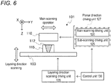
- FIG. 6 shows a configuration view explaining a configuration of a three-dimensional shaping device 101.
- the three-dimensional shaping device 101 includes a control unit 130 for controlling the entire shaping process, a head unit 110 having an ejection unit for ejecting droplets to become a material of a three-dimensional shaped object 112 and the like, and a shaping table 103 on which the three-dimensional shaped object 112 is layered and shaped.
- the shaping table 103 is a table-like member for supporting the three-dimensional shaped object 112 being shaped, and is arranged at a position facing the head unit 110, and has the three-dimensional shaped object 112 being shaped placed on the upper surface.
- the shaping table 103 is scanned in the layering direction by a layering direction scanning driving unit 135, and the relative positional relationship between the shaping table 103 and the head unit 110 in the Z direction in the figure is changed.
- the head unit 110 is two-dimensionally scanned in an XY plane in the figure. More specifically, the head unit 110 is driven by a main scanning driving unit 120 in the Y direction in the figure, which is a main scanning direction determined in advance, and the main scanning operation is performed.
- the main scanning operation is, for example, an operation of ejecting droplets of ink or the like for shaping while moving in the main scanning direction relatively to the three-dimensional shaped object 112 being shaped.
- the head unit 10 is driven and scanned by a sub-scanning driving unit 125 in the X direction in the figure, which is a sub-scanning direction.
- the driving unit for moving the head unit 10, more specifically, the main scanning driving unit 120, the sub-scanning driving unit 125, and the layering direction scanning driving unit 135 are controlled by the control unit 130, respectively.
- the three-dimensional shaping device includes the shaping table 103 on which droplets of ink or the like ejected from the ejection unit of the head unit 10 are layered.
- the shaping table 103 is, for example, an aluminum flat plate which surface is subjected to alumite-treatment, and the surface on a side where the ink is layered is desirably substantially flat so that the ink is flatly layered.
- irregularities actually exist on the surface of the shaping table which should be substantially flat.
- the surface of the shaping table has a guaranteed value in which, for example, an arithmetic average roughness is about 200 microns.
- ink droplets such as an ultraviolet curable resin are generally layered on a shaping table, but if the height of the shaped object to be shaped is, for example, about 5 mm, the influence of irregularities on the surface of the shaping table is not significant. However, the influence becomes larger as the shaped object becomes larger.
- FIG. 7A is an explanatory view explaining the surface roughness of the shaping table.
- the surface roughness of the shaping table has an undulation of, for example, 200 microns, specifically about ⁇ 100 microns with respect to the height of the average indicated with a chain dashed line.
- FIG. 7B assume that a support material ink is layered on the shaping table as a foundation (see Japanese Unexamined Patent Publication No. 2016-37040 ). Assuming that the shaping table has the surface roughness as described above, the surface of the foundation reflects the surface roughness of the shaping table even if the foundation is formed with the support material ink.
- the present disclosure provides a three-dimensional shaping method for shaping a three-dimensional shaped object according to a previously made design by compensating for the surface roughness of a shaping table.
- a supporting layer having a necessary and sufficient thickness and a flat surface is formed using a support material ink so as to compensate for the surface roughness of the shaping table, and the three-dimensional shaped object is shaped on the foundation.
- the surface roughness, specifically, irregularities and undulation of the upper surface of the shaping table are compensated by forming a flat foundation on the shaping table using the support material ink, and then the three-dimensional shaped object is formed thereafter, whereby the quality of the three-dimensional shaped object is improved.
- the support layer having a sufficient thickness is layered on the shaping table using the support material ink and then flattened, whereby a foundation having a flat surface can be formed, and the quality of the three-dimensional shaped object shaped on the foundation is improved.
- FIGs. 1 to 5 show one example of the embodiments of the disclosure, and portions denoted with the same reference numerals in the figure indicate the same parts. In each figure, the configuration of one part is appropriately omitted to simplify the figure. The size, shape, thickness and the like of the members are represented in an appropriately exaggerated manner.
- the three-dimensional shaping device 1 may have the same or similar configuration and features as the known three-dimensional shaping device described with reference to FIG. 6 , excluding the points particularly described. Specifically, the three-dimensional shaping device 1 has the same or similar features as those of a known shaping device that performs three-dimensional shaping by ejecting droplets of ink or the like that is to become a material of a shaped object using an inkjet head. Furthermore, other than the illustrated configuration, the three-dimensional shaping device 1 may also include, for example, various types of configurations necessary for shaping, and the like of the shaped object.
- FIG. 1A is an explanatory view explaining a configuration of a three-dimensional shaping device 1 used in a three-dimensional shaping method according to an embodiment of the present disclosure.
- the three-dimensional shaping device 1 includes a shaping table 3 having a substantially flat upper surface 23 on which a three-dimensional shaped object 20 is shaped, an ejection unit (not shown) for ejecting ink 17 for three-dimensional shaping provided in a head unit 10, a main scanning driving unit 120 (see FIG. 6 ) for causing the ejection unit to perform a main scanning operation of ejecting the ink 17 while relatively moving with respect to the three-dimensional shaped object 20 being shaped in a preset main scanning direction (Y direction in the figure) (see FIG.
- a sub-scanning driving unit 125 for relatively moving the ejection unit with respect to the three-dimensional shaped object 20 in the sub-scanning direction (X direction in the figure)
- a layering direction scanning driving unit 135 for causing a layering direction scanning of relatively moving the shaping table 3 with respect to the ejection unit to be performed in a layering direction, which is a direction in which the ink 17 is layered
- a flattening unit 5 for flattening the ejected and layered ink 17, and a control unit 130 (see FIG. 6 ) for controlling the shaping of the three-dimensional shaped object 20.
- the control unit 130 causes the ejection unit to shape a support layer (foundation) which is a structural object formed using a support material ink which is a material of a support layer 15 supporting the three-dimensional shaped object 20 being shaped and the three-dimensional shaped object 20 in this order while performing distance controlling of controlling a shaping table gap G (see FIG. 2A to be described later), which is the distance between the shaping table 3 and the flattening unit 5.
- a support layer foundation
- a support material ink which is a material of a support layer 15 supporting the three-dimensional shaped object 20 being shaped and the three-dimensional shaped object 20 in this order while performing distance controlling of controlling a shaping table gap G (see FIG. 2A to be described later), which is the distance between the shaping table 3 and the flattening unit 5.
- the three-dimensional shaping device 1 including the shaping table 3 having a substantially flat upper surface 23 on which the three-dimensional shaped object 20 is shaped, the ejection unit (not shown) for ejecting ink for the three-dimensional shaping, a planar direction driving unit 127 (see FIG.
- a layering direction scanning driving unit 135 for relatively separating the ejection unit and the shaping table in a layering direction, which is a direction perpendicularly intersecting the planar direction and a direction in which the ink is layered, and the flattening unit 5 for flattening the ejected and layered ink is used.
- the main scanning direction and the sub-scanning direction are together defined as the planar direction
- the main scanning driving unit 120 and the sub-scanning driving unit 125 are together defined as the planar direction driving unit 127.
- an operation of ejecting ink from the ejection unit while scanning in the planar direction is defined as a planar direction scanning operation.
- the support layer 15 (foundation 60 (see FIG. 4D to be described later) provided between the shaping table 3 and the three-dimensional shaped object 20 to support the three-dimensional shaped object 20 from the lower side includes a plurality of layers formed by layering a plurality of them on the shaping table 3 before shaping the three-dimensional shaped object 20, and the plurality of layers are such that a lower part side (base 40 (see FIG. 4D to be described later) in the vertical direction of the plurality of layers is formed only by the planar direction driving unit 127, and an upper part side (flattening base 57 (see FIG. 4D to be described later) in the vertical direction of the plurality of layers is formed using both the planar direction driving unit 127 and the layering direction scanning driving unit 135.
- the control unit 130 (see FIG. 6 ) carries out a control of causing the layering direction scanning driving unit 135 to carry out the drive of the layering direction scanning and increasing the shaping table gap G (see FIG. 2A to be described later) every time the ejection unit is caused to carry out the main scanning operation of predetermined number of times, specifically, number of passes on the same position of the three-dimensional shaped object 20 being shaped as the distance control of while shaping the three-dimensional shaped object 20.
- the control unit 130 carries out a first distance control of causing the ejection unit to perform the main scanning operation of a number of times greater than a predetermined number of times, specifically, number of passes to the same position of the base 40 being formed without changing the shaping table gap G, and a second distance control of increasing the shaping table gap G every time the ejection unit is caused to perform the main scanning operation of a predetermined number of times, specifically, number of passes to the same position of the flattening base 57 (upper part side in the vertical direction of a plurality of layers) being formed, as the distance control of forming the base (lower part side in the vertical direction of a plurality of layers) 40.
- the shaping table 3 is a table-shaped member that supports the shaped object 15 being shaped, and is disposed at a position facing the inkjet head in the head unit 10, and has the three-dimensional shaped object 20 being shaped placed on the upper surface thereof. Furthermore, in the three-dimensional shaping device 1, the shaping table 3 has a configuration in which at least the upper surface is movable in the layering direction, and at least the upper surface moves according to the progress of shaping of the three-dimensional shaped object 20 by being driven by the layering direction scanning driving unit 135 (see FIG. 6 ).
- the layering direction is, for example, a direction in which the material of shaping is layered in the layering shaping method.
- the layering direction is a direction (Z direction in the figure) orthogonal to the main scanning direction (Y direction in the figure) and the sub-scanning direction (X direction in the figure) set in advance in the three-dimensional shaping device 1.
- the main scanning driving unit 120 (see FIG. 6 ) further drives the ultraviolet light source 9 in the head unit 10. More specifically, the main scanning driving unit 120 cures the ink that landed on a surface-to-be-shaped of the three-dimensional shaped object 20 by, for example, lighting the ultraviolet light source 9 at the time of the main scanning operation.
- the surface-to-be-shaped of the three-dimensional shaped object 20 is, for example, a surface where a next layer of ink is formed by the head unit 10.
- the control unit includes a CPU, a RAM, a ROM, and the like, and executes various types of controls.
- the CPU is a so-called central processing unit, and various programs are executed to realize various functions.
- the RAM is used as a work area and a storage area of the CPU, and the ROM stores an operating system and programs executed by the CPU.
- FIG. 1B is an explanatory view of the inkjet head in the head unit 10. A more specific configuration of the head unit 10 will be described.
- FIG. 1B shows one example of a more detailed configuration of the head unit 10.
- the head unit 10 includes a plurality of color ink heads 160Y, 160M, 160C, 160K (hereinafter referred to as 160Y to 160K), a shaping material head 160Mo, a white ink head 160W, a clear ink head 160T, a support material head 160S, a plurality of ultraviolet light sources 9, and a flattening unit 5.
- the color ink heads 160Y to 160K, the shaping material head 160Mo, the white ink head 160W, the clear ink head 160T, and the support material head 160S are inkjet heads that eject droplets by an inkjet method.
- the color ink heads 160Y to 160K, the shaping material head 160Mo, the white ink head 160W, the clear ink head 160T, and the support material head 160S are inkjet heads that eject droplets of ultraviolet curable ink, and are arranged side by side in the main scanning direction (Y direction) with their positions in the sub-scanning direction (X direction) aligned.
- each of such inkjet heads includes a nozzle row, in which a plurality of nozzles 150 are lined in the sub-scanning direction, on a surface facing the shaping table 3.
- the nozzle 150 of each inkjet head eject droplets in a direction toward the shaping table 3.
- the arrangement of the color ink heads 160Y to 160K, the shaping material head 160Mo, the white ink head 160W, the clear ink head 160T, and the support material head 160S is not limited to the illustrated configuration, and may be variously changed.
- some inkjet heads may be arranged so as to be shifted in position in the sub-scanning direction from other inkjet heads.
- the head unit 10 may further include, for example, an inkjet head for colors such as light color, R (red) G (green) B (blue), orange and the like.
- the color ink heads 160Y to 160K are coloring inkjet heads that eject droplets of color inks of different colors, respectively.
- the color ink heads 160Y to 160K eject liquid droplets of ultraviolet curing ink of each color of Y (yellow), M (magenta), C (cyan), and K (black).
- the shaping material head 160Mo is an inkjet head that ejects droplets of ink used for shaping the inside of a shaped object, and for example, ejects droplets of ink used for shaping a region that is not colored in the shaped object 20.
- the shaping material head 160Mo ejects droplets of shaping ink of a predetermined color.
- the shaping ink may be, for example, an ink dedicated to shaping.
- the shaping ink is an ink having a color different from each color of CMYK. Consideration is made to using, for example, white ink, clear ink, or the like as the shaping ink.
- the white ink head 160W is an inkjet head that ejects droplets of white (W) ink.
- the clear ink head 160T is an inkjet head that ejects droplets of clear ink.
- the clear ink is, for example, a colorless transparent ink.
- the support material head 160S is an inkjet head that ejects droplets containing the material of the support layer 15.
- a water soluble material that can be dissolved in water after the shaping of the shaped object 20 can be suitably used for the material of the support layer 15.
- a material which curing degree by the ultraviolet light is weaker and which can be easily decomposed than the material configuring the shaped object 20 is preferably used.
- a known material for the support layer can be suitably used for the material of the support layer 15.
- the support layer 15 is, for example, a layered structural object formed under an overhang shape part during shaping, for example, in the case of shaping the shaped object 20 having an overhang shape.
- the support layer 15 is formed as necessary at the time of shaping of the shaped object 20 and removed after the completion of the shaping.
- the support material ink forming the support layer 15 is not used only for shaping the shaped object 20 having an overhang shape, but also for forming the base 40 covering the surface roughness of the shaping table 3.
- shaping material ink head 160Mo is present, but the shaping material ink head 160Mo may not be provided.
- the flattening unit 5 is a flattening means for flattening the layer of the ink 17 formed during the shaping of the shaped object 20 or the like.
- the flattening unit 5 includes at least a flattening roller 33 (see FIG. 2A to be described later) and is disposed between the arrangement of inkjet heads and the ultraviolet light source 9.
- the flattening unit 5 is arranged side by side in the main scanning direction (Y direction in the figure) with the positions in the sub-scanning direction (X direction in the figure) aligned with respect to the arrangement of the inkjet heads.
- the flattening roller 33 flattens the layer of ink by making contact with a surface of the layer of ink and removing one part of the ink before curing at the time of the main scanning operation.
- the head unit 10 includes only one flattening roller 33.
- the flattening unit 5 is arranged, for example, between the ultraviolet light source 9 on one end side in the head unit 10 and the arrangement of the inkjet heads.
- the main scanning driving unit 120 at least causes the head unit 10 to carry out the main scanning operation in a direction (one direction in the main scanning direction) in which the flattening unit 5 becomes the backward side than the arrangement of the inkjets. Then, the flattening unit 5 flattens the layer of ink during the main scanning operation in this direction.
- the plurality of ultraviolet light sources 9 have a configuration for curing the ink, and generate an ultraviolet light for curing the ultraviolet curable ink.
- UVLED ultraviolet LED
- each of the plurality of ultraviolet light sources 9 is arranged on one end side and the other end side in the main scanning direction in the head unit 10 so as to sandwich the arrangement of inkjet heads (color ink heads 160Y to 160K, shaping material head 160Mo, white ink head 160W, clear ink head 160T, support member head 160S) in between.
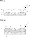
- FIG. 2A is an explanatory view explaining the surface roughness on the upper surface 23 of the shaping table 3 and the shaping table gap G, which is the distance between the shaping table 3 and the flattening unit 5.
- the shaping table gap G is defined as the difference between, for example, a lower surface part 35 of the flattening roller and the height of a summit portion 25 of the undulation on the upper surface 23 of the shaping table 3.
- the shaping table 3 is a flat plate in which the upper surface 23 is substantially flat, but actually has surface roughness.
- the difference in the Z direction specifically a distance D between the summit portion 25 where the distance from the lower surface part 35 of the flattening roller becomes the closest and a valley portion (bottom portion) 30 where the distance from the lower surface part 35 of the flattening roller becomes the farthest corresponds to, for example, the surface roughness or 200 microns, specifically, arithmetic average roughness or ten point average roughness, or the like.
- a plane including the lower surface part 35 of the flattening roller and being parallel to the XY plane is a flattened surface U
- a plane including the summit portion 25 of the undulation on the upper surface 23 of the shaping table 3 and being parallel to the XY plane is a summit surface VI
- a plane including the valley bottom (bottom portion) of the valley portion 30 of the undulation on the upper surface 23 of the shaping table 3 is a valley bottom surface V2
- the distance in the Z direction of the flattened surface U and the summit surface V1 is defined as the shaping table gap G.
- the distance in the Z direction between the summit surface V1 and the valley bottom surface V2 corresponds to D.
- the sum of the size of the shaping table gap G and the size D of the surface roughness is desirably greater than or equal to twice the surface roughness of the upper surface 23 of the shaping table 3.
- the shaping table gap G is desirably 400 microns to 600 microns, specifically 500 microns.
- FIG. 2B is an explanatory view explaining a mode in which the base 40 is formed on the shaping table 3 using the support material ink without changing the shaping table gap G.
- the thickness T1 of the base 40 is greater than the surface roughness of the upper surface 23 of the shaping table 3.
- the thickness T1 of the base is desirably, for example, 300 microns.
- the support material ink forming the base 40 having the thickness T1 is realized by carrying out layering of 5 layers to 15 layers when, for example, layering 35 microns for every main scanning operation of a predetermined number of times, specifically, number of passes.
- FIG. 1 is an explanatory view explaining a mode in which the base 40 is formed on the shaping table 3 using the support material ink without changing the shaping table gap G.
- the thickness T1 of the base 40 is greater than the surface roughness of the upper surface 23 of the shaping table 3.
- the thickness T1 of the base is desirably, for example, 300 microns.
- the base summit surface V3 including the summit portion 45 of the base and being parallel to the XY plane and the flattened surface U including the lower surface portion 35 of the flattening roller and being parallel to the XY plane desirably substantially coincide.
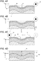
- FIG. 3A is an explanatory view explaining a mode in which the first flattening base 50 is further layered using the support material ink by the head unit 10 (see FIG. 1B ).
- the thickness of the first flattening base 50 is T2, and takes, for example, a value between 10 microns and 100 microns, specifically 35 microns.
- FIG. 3B is an explanatory view explaining a mode in which the shaping table 3 is moved in the positive direction in the Z direction in the figure to increase the shaping table gap G.
- the first flattening base 50 is not irradiated with ultraviolet light from the ultraviolet light source 9 (see FIG. 1A ), and the first flattening base 50 is not cured.
- the moving distance M1 of the shaping table is, for example, 30 microns.
- FIG. 3C is an explanatory view explaining a mode in which the first flattening base 50 is flattened by the flattening unit 5 (see FIG. 1A ). More specifically, the flattening roller 33 is moved in the main scanning direction, more specifically in the negative direction in the Y direction in the figure, thereby scraping off the ink forming the first flattening base 50. Therefore, for example, when the thickness T2 of the base is 35 microns, the first flattening base 50 is scraped off by 5 microns and the flat portion P is formed.
- the flattening unit 5 does not make contact with the support layer which is the base being formed during the first distance control (see FIG. 2B ), and the flattening unit 5 makes contact with the support layer which is the upper part side (flattening base 57 (see FIG. 4D )) in the vertical direction of a plurality of layers being formed during the main scanning operation of at least a few times (see e.g., FIG. 3C ) during the second distance control.
- control unit causes the layering direction scanning driving unit 135 to carry out the layering direction scanning operation of a predetermined distance every time the main scanning operation of a predetermined number of times, specifically, number of passes is carried out with respect to each position on the upper part side in the vertical direction of a plurality of layers during the second distance control (see FIG. 3B ).
- FIG. 4A is an explanatory view explaining a mode in which the second flattening base 55 is further layered with the head unit 10 using the support material ink.
- the second flattening base 55 is formed on the first flattening base 50 by further ejecting the support material ink from the head unit 10 (see FIG. 1A ).
- the thickness T2 of the second flattening base 55 is 35 microns.
- FIG. 4B is an explanatory view explaining a mode in which the shaping table 3 is further moved in the positive direction in the Z direction to increase the shaping table gap G.
- the first flattening base 50 has already been irradiated with ultraviolet light from the ultraviolet light source 9 and the curing is completed, but the second flattening base 55 is not irradiated with ultraviolet light from the ultraviolet light source 9 (see FIG. 1A ), and the second flattening base 55 is not cured.
- the moving distance M2 of the shaping table is, for example, 30 microns.
- FIG. 4C is an explanatory view explaining a mode in which the first flattening base 55 is flattened by the flattening unit 5 (see FIG. 1A ).
- the flattening roller 33 is moved in the main scanning direction, more specifically, in the negative direction in the Y direction in the figure, thereby scraping off the ink forming the second flattening base 55. Therefore, for example, when the thickness T3 of the base is 35 microns, the second flattening base 55 is scraped by 5 microns so that the flat portion P is formed wider than in FIG. 3C .
- the depth of the valley portion 30 being shallower by 5 microns.
- FIG. 4D is an explanatory view explaining a mode in which the valley portion 30 is filled with the support material ink and the upper surface of the foundation 60 on which the three-dimensional shaped object is shaped is flattened.
- the valley portion 30 has the depth of D, specifically, 200 microns as shown in FIG. 2B
- 40 layers to 50 layers are layered as the flattening base 57 so that the surface roughness of the shaping table 3 is compensated by the foundation 60 and a flat upper surface 70 formed by using the support material ink is obtained.
- the compensation of the surface roughness described above can be represented as having the distance between the upper surface of the support layer, which is the foundation, and the bottom portion of the deepest valley greater than the maximum height, which is the sum of the height of the mountain having the highest surface roughness of the shaping table 3 and the depth of the deepest valley.
- the support layer of sufficient thickness is layered on the shaping table 3 using the support material ink and then flattened, so that the foundation 60 having a flat surface can be formed, and an excellent effect is obtained in that the quality of the three-dimensional shaped object 20 to be shaped on the foundation 60 is improved.
- the layering time for eliminating the surface roughness of the shaping table 3 can be shortened since the shaping table 3 is not moved in the layering direction. Furthermore, when forming the upper part side 57, an excellent effect is obtained in that the interference of the flattening unit 5, the ink layered and cured as the lower part side 40, and the ejection unit can be prevented by lowering the shaping table.
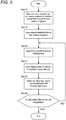
- the sum of the shaping table gap G and the surface roughness is set to a distance greater than or equal to twice the surface roughness (step S1). At this time, the distance may be controlled by the control unit using various distance meters or the like.
- the support material ink is layered thicker than the surface roughness (step S2). For example, when the surface roughness, more specifically, the ten point average roughness is 200 microns, the support material ink is layered for, for example, 220 microns. Thereafter, although not shown, the support material ink is cured by the ultraviolet light source 9. Then, the support material ink is further layered as the flattening base 57 (step S3). At this time, the thickness to be layered is defined as T.
- the shaping table 3 (see FIG. 1A ) is lowered in the Z direction to enlarge the shaping table gap G (Step S4). Defining the distance by which the shaping table gap G is enlarged as M, T > M is desired for flattening, which is the next step.
- the layered flattening base is flattened by the flattening unit 5 (see FIG. 1A ), and then irradiated with the ultraviolet light by the ultraviolet light source 9 to cure the flattening base (step S5).
- the valley portion 30 (see e.g., FIG. 3C ) is filled and irregularities reflecting the surface roughness of the shaping table 3 are eliminated, the flattening operation is terminated (YES side of step S6).
- step S6 When the valley portion 30 (see, e.g., FIG. 3C ) is remained and the irregularities reflecting the surface roughness of the shaping table 3 have not been eliminated, the process returns to step S3 and the flattening base is further layered (NO side of step S6).
- the three-dimensional shaping method of the embodiment of the present disclosure an excellent effect is obtained in that the surface roughness, specifically, the irregularities and undulation of the upper surface of the shaping table can be compensated using the support material ink on the shaping table with the minimum number of layering.
- the control unit that carries out the control of the entire three-dimensional shaping device controls the ejection unit to form on the shaping table the support layer, which supports the three-dimensional shaped object being shaped from the lower side in the vertical direction, and the three-dimensional shaped object in such order on the shaping table.
- the foundation 60 having a flat surface can be formed by layering and flattening the support layer of sufficient thickness on the shaping table 3 using the support material ink, so that an excellent effect is obtained in that the quality of the three-dimensional shaped object to be shaped on the foundation 60 is improved.
- the layering time for eliminating the surface roughness of the shaping table 3 can be shortened since the shaping table 3 is not moved in the layering direction.
- an excellent effect is obtained in that the interference of the flattening unit 5, the ink layered and cured as the lower part side 40, and the ejection unit can be prevented by lowering the shaping table 3.
- the ejection unit and the shaping table 3 can be relatively separated in the layering direction every time one layer of the upper part side 57 of the support layer is layered, an effect is obtained in that the interference between the cured ink and the ejecting unit can be prevented.
- the layering direction scanning distance which is the distance change amount in the layering direction
- the thickness of layering the upper part side 57 of the support layer is ensured.
- the shaping table gap G which is the distance between the shaping table 3 and the flattening unit 5
- the shaping table gap G which is the distance between the shaping table 3 and the flattening unit 5
- an effect is obtained in that the time for scanning the shaping table 3 in the layering direction can be reduced and the time for shaping can be reduced.
- a support layer having a flat surface can be formed since the surface can be flattened. Therefore, the quality of the three-dimensional shaped object to be shaped on the support layer is improved.
- the sum of the shaping table gap G, which is the distance between the shaping table 3 and the flattening unit 5, and the surface roughness of the upper surface 23 of the shaping table 3 is made to a distance greater than or equal to twice the surface roughness in advance, and hence an excellent effect is obtained in that the support layer formed using the support material ink can be layered with a sufficient thickness.
- the lower part side 40 of the support layer is layered thicker than the upper part side 57 so that the number of layering for the foundation can be reduced and consequently the layering time can be shortened.
- the thickness layered on the lower part side 40 of the plurality of layers is larger than the surface roughness on the upper surface of the shaping table, the quality of the three-dimensional shaped object shaped on the support layer is improved and the upper surface 23 of the shaping table 3 is reliably covered with the support layer, so that an excellent effect is obtained in that the three-dimensional shaped object shaped thereon can be easily detached from the shaping table.
- the surface roughness, specifically, irregularities and undulation of the upper surface 23 of the shaping table 3 is compensated by forming the flat foundation 60 using the support material ink on the shaping table 3 and then the three-dimensional shaped object is formed, so that the quality of the three-dimensional shaped object is improved.
- a base having a sufficient thickness is layered on the shaping table using a support material ink and then flattened so that a base having a flat surface can be formed, and hence an excellent effect is obtained in that the quality of the three-dimensional shaped object shaped on the base is improved.
Landscapes
- Chemical & Material Sciences (AREA)
- Engineering & Computer Science (AREA)
- Materials Engineering (AREA)
- Manufacturing & Machinery (AREA)
- Physics & Mathematics (AREA)
- Mechanical Engineering (AREA)
- Optics & Photonics (AREA)
Applications Claiming Priority (1)
| Application Number | Priority Date | Filing Date | Title |
|---|---|---|---|
| JP2018025674A JP6991078B2 (ja) | 2018-02-16 | 2018-02-16 | 立体造形方法 |
Publications (2)
| Publication Number | Publication Date |
|---|---|
| EP3530459A1 true EP3530459A1 (de) | 2019-08-28 |
| EP3530459B1 EP3530459B1 (de) | 2023-12-20 |
Family
ID=65365817
Family Applications (1)
| Application Number | Title | Priority Date | Filing Date |
|---|---|---|---|
| EP19156114.1A Active EP3530459B1 (de) | 2018-02-16 | 2019-02-08 | Verfahren zur dreidimensionalen formung |
Country Status (3)
| Country | Link |
|---|---|
| US (1) | US11440250B2 (de) |
| EP (1) | EP3530459B1 (de) |
| JP (1) | JP6991078B2 (de) |
Families Citing this family (2)
| Publication number | Priority date | Publication date | Assignee | Title |
|---|---|---|---|---|
| EP4037890B1 (de) | 2019-09-30 | 2025-05-07 | Evolve Additive Solutions, Inc. | System zur generativen fertigung und verfahren mit verbessertem oberflächenfinish |
| CN112277308B (zh) * | 2020-10-09 | 2022-07-19 | 业成科技(成都)有限公司 | 三维打印成型产品及其制造方法、以及支撑治具 |
Citations (3)
| Publication number | Priority date | Publication date | Assignee | Title |
|---|---|---|---|---|
| JP2016037040A (ja) | 2014-08-08 | 2016-03-22 | 株式会社ミマキエンジニアリング | 三次元印刷装置および三次元印刷方法 |
| US20160107382A1 (en) * | 2014-10-17 | 2016-04-21 | Seiko Epson Corporation | Three-dimensionally shaped article production method, three-dimensionally shaped article production apparatus, and three-dimensionally shaped article |
| US20160198576A1 (en) * | 2013-06-24 | 2016-07-07 | President And Fellows Of Harvard College | Printed three-dimensional (3d) functional part and method of making |
Family Cites Families (6)
| Publication number | Priority date | Publication date | Assignee | Title |
|---|---|---|---|---|
| US6850334B1 (en) * | 2000-01-18 | 2005-02-01 | Objet Geometries Ltd | System and method for three dimensional model printing |
| US20070063366A1 (en) * | 2005-09-19 | 2007-03-22 | 3D Systems, Inc. | Removal of fluid by-product from a solid deposition modeling process |
| US20180117845A1 (en) * | 2015-05-29 | 2018-05-03 | Velo3D, Inc. | Three-dimensional printing |
| CN106273453B (zh) * | 2015-06-05 | 2018-09-25 | 三纬国际立体列印科技股份有限公司 | 立体印刷装置与其印刷误差校正方法 |
| CN107031062B (zh) | 2015-07-14 | 2019-03-05 | 三纬国际立体列印科技股份有限公司 | 三维打印物件的感测装置 |
| JP2017109324A (ja) * | 2015-12-14 | 2017-06-22 | 株式会社ミマキエンジニアリング | 立体物造形装置および調整方法 |
-
2018
- 2018-02-16 JP JP2018025674A patent/JP6991078B2/ja active Active
-
2019
- 2019-01-30 US US16/261,567 patent/US11440250B2/en active Active
- 2019-02-08 EP EP19156114.1A patent/EP3530459B1/de active Active
Patent Citations (3)
| Publication number | Priority date | Publication date | Assignee | Title |
|---|---|---|---|---|
| US20160198576A1 (en) * | 2013-06-24 | 2016-07-07 | President And Fellows Of Harvard College | Printed three-dimensional (3d) functional part and method of making |
| JP2016037040A (ja) | 2014-08-08 | 2016-03-22 | 株式会社ミマキエンジニアリング | 三次元印刷装置および三次元印刷方法 |
| US20160107382A1 (en) * | 2014-10-17 | 2016-04-21 | Seiko Epson Corporation | Three-dimensionally shaped article production method, three-dimensionally shaped article production apparatus, and three-dimensionally shaped article |
Also Published As
| Publication number | Publication date |
|---|---|
| US20190255769A1 (en) | 2019-08-22 |
| JP2019142008A (ja) | 2019-08-29 |
| EP3530459B1 (de) | 2023-12-20 |
| JP6991078B2 (ja) | 2022-01-12 |
| US11440250B2 (en) | 2022-09-13 |
Similar Documents
| Publication | Publication Date | Title |
|---|---|---|
| US20200130255A1 (en) | Method for modeling three-dimensional object | |
| JP6396723B2 (ja) | 液滴吐出装置及び液滴吐出方法 | |
| US10065376B2 (en) | Three-dimensional object fabrication device, three-dimensional object fabrication method, and three-dimensional object | |
| EP3056332A1 (de) | Flüssigkeitsabgabevorrichtung und flüssigkeitsabgabeverfahren | |
| EP3323599B1 (de) | Formvorrichtung und formverfahren | |
| US20180162056A1 (en) | Shaping method, shaping system, and shaping device | |
| US11260593B2 (en) | Shaping device and shaping method | |
| JP6861053B2 (ja) | 造形装置及び造形方法 | |
| US11440250B2 (en) | Three-dimensional shaping method | |
| US10532516B2 (en) | Shaping method, shaping system, and shaping device | |
| JP6935544B2 (ja) | 造形装置 | |
| US11148353B2 (en) | Manufacturing method for shaped object, shaping system, and shaping device | |
| JP2018065308A (ja) | 造形装置及び造形方法 | |
| US20190248074A1 (en) | Shaping device and shaping method | |
| JP2013119244A (ja) | デジタル制御式uvインクジェットで立体パターンを印刷する方法 | |
| JP7345977B2 (ja) | 印刷装置及び印刷方法 | |
| JP2021045913A (ja) | 印刷装置及び印刷方法 | |
| US11141933B2 (en) | Shaping apparatus, shaping method, and shaped object | |
| JP7750760B2 (ja) | 造形装置の調整方法、造形システム、及び確認用造形物の製造方法 | |
| US11623391B2 (en) | Three-dimensional shaping device and manufacturing method for three-dimensional shaped object | |
| US20200198247A1 (en) | Shaping device and shaping method | |
| US12030321B2 (en) | Printing device and printing method | |
| JP2020131626A (ja) | 造形装置及び造形方法 | |
| JP2018114655A (ja) | 立体物造形方法及び立体物造形装置 |
Legal Events
| Date | Code | Title | Description |
|---|---|---|---|
| PUAI | Public reference made under article 153(3) epc to a published international application that has entered the european phase |
Free format text: ORIGINAL CODE: 0009012 |
|
| STAA | Information on the status of an ep patent application or granted ep patent |
Free format text: STATUS: THE APPLICATION HAS BEEN PUBLISHED |
|
| AK | Designated contracting states |
Kind code of ref document: A1 Designated state(s): AL AT BE BG CH CY CZ DE DK EE ES FI FR GB GR HR HU IE IS IT LI LT LU LV MC MK MT NL NO PL PT RO RS SE SI SK SM TR |
|
| AX | Request for extension of the european patent |
Extension state: BA ME |
|
| STAA | Information on the status of an ep patent application or granted ep patent |
Free format text: STATUS: REQUEST FOR EXAMINATION WAS MADE |
|
| STAA | Information on the status of an ep patent application or granted ep patent |
Free format text: STATUS: EXAMINATION IS IN PROGRESS |
|
| 17P | Request for examination filed |
Effective date: 20200228 |
|
| RBV | Designated contracting states (corrected) |
Designated state(s): AL AT BE BG CH CY CZ DE DK EE ES FI FR GB GR HR HU IE IS IT LI LT LU LV MC MK MT NL NO PL PT RO RS SE SI SK SM TR |
|
| 17Q | First examination report despatched |
Effective date: 20200402 |
|
| GRAP | Despatch of communication of intention to grant a patent |
Free format text: ORIGINAL CODE: EPIDOSNIGR1 |
|
| STAA | Information on the status of an ep patent application or granted ep patent |
Free format text: STATUS: GRANT OF PATENT IS INTENDED |
|
| INTG | Intention to grant announced |
Effective date: 20230502 |
|
| GRAJ | Information related to disapproval of communication of intention to grant by the applicant or resumption of examination proceedings by the epo deleted |
Free format text: ORIGINAL CODE: EPIDOSDIGR1 |
|
| STAA | Information on the status of an ep patent application or granted ep patent |
Free format text: STATUS: EXAMINATION IS IN PROGRESS |
|
| INTC | Intention to grant announced (deleted) | ||
| GRAP | Despatch of communication of intention to grant a patent |
Free format text: ORIGINAL CODE: EPIDOSNIGR1 |
|
| STAA | Information on the status of an ep patent application or granted ep patent |
Free format text: STATUS: GRANT OF PATENT IS INTENDED |
|
| GRAS | Grant fee paid |
Free format text: ORIGINAL CODE: EPIDOSNIGR3 |
|
| GRAA | (expected) grant |
Free format text: ORIGINAL CODE: 0009210 |
|
| STAA | Information on the status of an ep patent application or granted ep patent |
Free format text: STATUS: THE PATENT HAS BEEN GRANTED |
|
| INTG | Intention to grant announced |
Effective date: 20231026 |
|
| AK | Designated contracting states |
Kind code of ref document: B1 Designated state(s): AL AT BE BG CH CY CZ DE DK EE ES FI FR GB GR HR HU IE IS IT LI LT LU LV MC MK MT NL NO PL PT RO RS SE SI SK SM TR |
|
| REG | Reference to a national code |
Ref country code: GB Ref legal event code: FG4D |
|
| REG | Reference to a national code |
Ref country code: CH Ref legal event code: EP |
|
| REG | Reference to a national code |
Ref country code: DE Ref legal event code: R096 Ref document number: 602019043459 Country of ref document: DE |
|
| REG | Reference to a national code |
Ref country code: IE Ref legal event code: FG4D |
|
| PG25 | Lapsed in a contracting state [announced via postgrant information from national office to epo] |
Ref country code: GR Free format text: LAPSE BECAUSE OF FAILURE TO SUBMIT A TRANSLATION OF THE DESCRIPTION OR TO PAY THE FEE WITHIN THE PRESCRIBED TIME-LIMIT Effective date: 20240321 |
|
| REG | Reference to a national code |
Ref country code: LT Ref legal event code: MG9D |
|
| PG25 | Lapsed in a contracting state [announced via postgrant information from national office to epo] |
Ref country code: LT Free format text: LAPSE BECAUSE OF FAILURE TO SUBMIT A TRANSLATION OF THE DESCRIPTION OR TO PAY THE FEE WITHIN THE PRESCRIBED TIME-LIMIT Effective date: 20231220 |
|
| REG | Reference to a national code |
Ref country code: NL Ref legal event code: MP Effective date: 20231220 |
|
| PG25 | Lapsed in a contracting state [announced via postgrant information from national office to epo] |
Ref country code: ES Free format text: LAPSE BECAUSE OF FAILURE TO SUBMIT A TRANSLATION OF THE DESCRIPTION OR TO PAY THE FEE WITHIN THE PRESCRIBED TIME-LIMIT Effective date: 20231220 |
|
| PG25 | Lapsed in a contracting state [announced via postgrant information from national office to epo] |
Ref country code: LT Free format text: LAPSE BECAUSE OF FAILURE TO SUBMIT A TRANSLATION OF THE DESCRIPTION OR TO PAY THE FEE WITHIN THE PRESCRIBED TIME-LIMIT Effective date: 20231220 Ref country code: GR Free format text: LAPSE BECAUSE OF FAILURE TO SUBMIT A TRANSLATION OF THE DESCRIPTION OR TO PAY THE FEE WITHIN THE PRESCRIBED TIME-LIMIT Effective date: 20240321 Ref country code: FI Free format text: LAPSE BECAUSE OF FAILURE TO SUBMIT A TRANSLATION OF THE DESCRIPTION OR TO PAY THE FEE WITHIN THE PRESCRIBED TIME-LIMIT Effective date: 20231220 Ref country code: ES Free format text: LAPSE BECAUSE OF FAILURE TO SUBMIT A TRANSLATION OF THE DESCRIPTION OR TO PAY THE FEE WITHIN THE PRESCRIBED TIME-LIMIT Effective date: 20231220 Ref country code: BG Free format text: LAPSE BECAUSE OF FAILURE TO SUBMIT A TRANSLATION OF THE DESCRIPTION OR TO PAY THE FEE WITHIN THE PRESCRIBED TIME-LIMIT Effective date: 20240320 |
|
| REG | Reference to a national code |
Ref country code: AT Ref legal event code: MK05 Ref document number: 1642159 Country of ref document: AT Kind code of ref document: T Effective date: 20231220 |
|
| PG25 | Lapsed in a contracting state [announced via postgrant information from national office to epo] |
Ref country code: NL Free format text: LAPSE BECAUSE OF FAILURE TO SUBMIT A TRANSLATION OF THE DESCRIPTION OR TO PAY THE FEE WITHIN THE PRESCRIBED TIME-LIMIT Effective date: 20231220 |
|
| PG25 | Lapsed in a contracting state [announced via postgrant information from national office to epo] |
Ref country code: SE Free format text: LAPSE BECAUSE OF FAILURE TO SUBMIT A TRANSLATION OF THE DESCRIPTION OR TO PAY THE FEE WITHIN THE PRESCRIBED TIME-LIMIT Effective date: 20231220 Ref country code: RS Free format text: LAPSE BECAUSE OF FAILURE TO SUBMIT A TRANSLATION OF THE DESCRIPTION OR TO PAY THE FEE WITHIN THE PRESCRIBED TIME-LIMIT Effective date: 20231220 Ref country code: NO Free format text: LAPSE BECAUSE OF FAILURE TO SUBMIT A TRANSLATION OF THE DESCRIPTION OR TO PAY THE FEE WITHIN THE PRESCRIBED TIME-LIMIT Effective date: 20240320 Ref country code: NL Free format text: LAPSE BECAUSE OF FAILURE TO SUBMIT A TRANSLATION OF THE DESCRIPTION OR TO PAY THE FEE WITHIN THE PRESCRIBED TIME-LIMIT Effective date: 20231220 Ref country code: LV Free format text: LAPSE BECAUSE OF FAILURE TO SUBMIT A TRANSLATION OF THE DESCRIPTION OR TO PAY THE FEE WITHIN THE PRESCRIBED TIME-LIMIT Effective date: 20231220 Ref country code: HR Free format text: LAPSE BECAUSE OF FAILURE TO SUBMIT A TRANSLATION OF THE DESCRIPTION OR TO PAY THE FEE WITHIN THE PRESCRIBED TIME-LIMIT Effective date: 20231220 |
|
| PG25 | Lapsed in a contracting state [announced via postgrant information from national office to epo] |
Ref country code: IS Free format text: LAPSE BECAUSE OF FAILURE TO SUBMIT A TRANSLATION OF THE DESCRIPTION OR TO PAY THE FEE WITHIN THE PRESCRIBED TIME-LIMIT Effective date: 20240420 |
|
| PG25 | Lapsed in a contracting state [announced via postgrant information from national office to epo] |
Ref country code: AT Free format text: LAPSE BECAUSE OF FAILURE TO SUBMIT A TRANSLATION OF THE DESCRIPTION OR TO PAY THE FEE WITHIN THE PRESCRIBED TIME-LIMIT Effective date: 20231220 Ref country code: CZ Free format text: LAPSE BECAUSE OF FAILURE TO SUBMIT A TRANSLATION OF THE DESCRIPTION OR TO PAY THE FEE WITHIN THE PRESCRIBED TIME-LIMIT Effective date: 20231220 |
|
| PG25 | Lapsed in a contracting state [announced via postgrant information from national office to epo] |
Ref country code: SK Free format text: LAPSE BECAUSE OF FAILURE TO SUBMIT A TRANSLATION OF THE DESCRIPTION OR TO PAY THE FEE WITHIN THE PRESCRIBED TIME-LIMIT Effective date: 20231220 |
|
| PG25 | Lapsed in a contracting state [announced via postgrant information from national office to epo] |
Ref country code: SM Free format text: LAPSE BECAUSE OF FAILURE TO SUBMIT A TRANSLATION OF THE DESCRIPTION OR TO PAY THE FEE WITHIN THE PRESCRIBED TIME-LIMIT Effective date: 20231220 Ref country code: SK Free format text: LAPSE BECAUSE OF FAILURE TO SUBMIT A TRANSLATION OF THE DESCRIPTION OR TO PAY THE FEE WITHIN THE PRESCRIBED TIME-LIMIT Effective date: 20231220 Ref country code: RO Free format text: LAPSE BECAUSE OF FAILURE TO SUBMIT A TRANSLATION OF THE DESCRIPTION OR TO PAY THE FEE WITHIN THE PRESCRIBED TIME-LIMIT Effective date: 20231220 Ref country code: IT Free format text: LAPSE BECAUSE OF FAILURE TO SUBMIT A TRANSLATION OF THE DESCRIPTION OR TO PAY THE FEE WITHIN THE PRESCRIBED TIME-LIMIT Effective date: 20231220 Ref country code: IS Free format text: LAPSE BECAUSE OF FAILURE TO SUBMIT A TRANSLATION OF THE DESCRIPTION OR TO PAY THE FEE WITHIN THE PRESCRIBED TIME-LIMIT Effective date: 20240420 Ref country code: EE Free format text: LAPSE BECAUSE OF FAILURE TO SUBMIT A TRANSLATION OF THE DESCRIPTION OR TO PAY THE FEE WITHIN THE PRESCRIBED TIME-LIMIT Effective date: 20231220 Ref country code: CZ Free format text: LAPSE BECAUSE OF FAILURE TO SUBMIT A TRANSLATION OF THE DESCRIPTION OR TO PAY THE FEE WITHIN THE PRESCRIBED TIME-LIMIT Effective date: 20231220 Ref country code: AT Free format text: LAPSE BECAUSE OF FAILURE TO SUBMIT A TRANSLATION OF THE DESCRIPTION OR TO PAY THE FEE WITHIN THE PRESCRIBED TIME-LIMIT Effective date: 20231220 |
|
| PG25 | Lapsed in a contracting state [announced via postgrant information from national office to epo] |
Ref country code: PL Free format text: LAPSE BECAUSE OF FAILURE TO SUBMIT A TRANSLATION OF THE DESCRIPTION OR TO PAY THE FEE WITHIN THE PRESCRIBED TIME-LIMIT Effective date: 20231220 Ref country code: PT Free format text: LAPSE BECAUSE OF FAILURE TO SUBMIT A TRANSLATION OF THE DESCRIPTION OR TO PAY THE FEE WITHIN THE PRESCRIBED TIME-LIMIT Effective date: 20240422 |
|
| PG25 | Lapsed in a contracting state [announced via postgrant information from national office to epo] |
Ref country code: PT Free format text: LAPSE BECAUSE OF FAILURE TO SUBMIT A TRANSLATION OF THE DESCRIPTION OR TO PAY THE FEE WITHIN THE PRESCRIBED TIME-LIMIT Effective date: 20240422 Ref country code: PL Free format text: LAPSE BECAUSE OF FAILURE TO SUBMIT A TRANSLATION OF THE DESCRIPTION OR TO PAY THE FEE WITHIN THE PRESCRIBED TIME-LIMIT Effective date: 20231220 |
|
| REG | Reference to a national code |
Ref country code: DE Ref legal event code: R097 Ref document number: 602019043459 Country of ref document: DE |
|
| PG25 | Lapsed in a contracting state [announced via postgrant information from national office to epo] |
Ref country code: MC Free format text: LAPSE BECAUSE OF FAILURE TO SUBMIT A TRANSLATION OF THE DESCRIPTION OR TO PAY THE FEE WITHIN THE PRESCRIBED TIME-LIMIT Effective date: 20231220 |
|
| REG | Reference to a national code |
Ref country code: CH Ref legal event code: PL |
|
| PG25 | Lapsed in a contracting state [announced via postgrant information from national office to epo] |
Ref country code: DK Free format text: LAPSE BECAUSE OF FAILURE TO SUBMIT A TRANSLATION OF THE DESCRIPTION OR TO PAY THE FEE WITHIN THE PRESCRIBED TIME-LIMIT Effective date: 20231220 |
|
| PG25 | Lapsed in a contracting state [announced via postgrant information from national office to epo] |
Ref country code: LU Free format text: LAPSE BECAUSE OF NON-PAYMENT OF DUE FEES Effective date: 20240208 |
|
| PG25 | Lapsed in a contracting state [announced via postgrant information from national office to epo] |
Ref country code: CH Free format text: LAPSE BECAUSE OF NON-PAYMENT OF DUE FEES Effective date: 20240229 |
|
| PLBE | No opposition filed within time limit |
Free format text: ORIGINAL CODE: 0009261 |
|
| STAA | Information on the status of an ep patent application or granted ep patent |
Free format text: STATUS: NO OPPOSITION FILED WITHIN TIME LIMIT |
|
| PG25 | Lapsed in a contracting state [announced via postgrant information from national office to epo] |
Ref country code: SI Free format text: LAPSE BECAUSE OF FAILURE TO SUBMIT A TRANSLATION OF THE DESCRIPTION OR TO PAY THE FEE WITHIN THE PRESCRIBED TIME-LIMIT Effective date: 20231220 |
|
| PG25 | Lapsed in a contracting state [announced via postgrant information from national office to epo] |
Ref country code: SI Free format text: LAPSE BECAUSE OF FAILURE TO SUBMIT A TRANSLATION OF THE DESCRIPTION OR TO PAY THE FEE WITHIN THE PRESCRIBED TIME-LIMIT Effective date: 20231220 Ref country code: LU Free format text: LAPSE BECAUSE OF NON-PAYMENT OF DUE FEES Effective date: 20240208 Ref country code: DK Free format text: LAPSE BECAUSE OF FAILURE TO SUBMIT A TRANSLATION OF THE DESCRIPTION OR TO PAY THE FEE WITHIN THE PRESCRIBED TIME-LIMIT Effective date: 20231220 Ref country code: CH Free format text: LAPSE BECAUSE OF NON-PAYMENT OF DUE FEES Effective date: 20240229 |
|
| 26N | No opposition filed |
Effective date: 20240923 |
|
| GBPC | Gb: european patent ceased through non-payment of renewal fee |
Effective date: 20240320 |
|
| REG | Reference to a national code |
Ref country code: BE Ref legal event code: MM Effective date: 20240229 |
|
| PG25 | Lapsed in a contracting state [announced via postgrant information from national office to epo] |
Ref country code: BE Free format text: LAPSE BECAUSE OF NON-PAYMENT OF DUE FEES Effective date: 20240229 |
|
| PG25 | Lapsed in a contracting state [announced via postgrant information from national office to epo] |
Ref country code: GB Free format text: LAPSE BECAUSE OF NON-PAYMENT OF DUE FEES Effective date: 20240320 |
|
| PG25 | Lapsed in a contracting state [announced via postgrant information from national office to epo] |
Ref country code: FR Free format text: LAPSE BECAUSE OF NON-PAYMENT OF DUE FEES Effective date: 20240220 |
|
| PG25 | Lapsed in a contracting state [announced via postgrant information from national office to epo] |
Ref country code: IE Free format text: LAPSE BECAUSE OF NON-PAYMENT OF DUE FEES Effective date: 20240208 |
|
| PG25 | Lapsed in a contracting state [announced via postgrant information from national office to epo] |
Ref country code: IE Free format text: LAPSE BECAUSE OF NON-PAYMENT OF DUE FEES Effective date: 20240208 Ref country code: GB Free format text: LAPSE BECAUSE OF NON-PAYMENT OF DUE FEES Effective date: 20240320 Ref country code: FR Free format text: LAPSE BECAUSE OF NON-PAYMENT OF DUE FEES Effective date: 20240220 Ref country code: BE Free format text: LAPSE BECAUSE OF NON-PAYMENT OF DUE FEES Effective date: 20240229 |
|
| PG25 | Lapsed in a contracting state [announced via postgrant information from national office to epo] |
Ref country code: CY Free format text: LAPSE BECAUSE OF FAILURE TO SUBMIT A TRANSLATION OF THE DESCRIPTION OR TO PAY THE FEE WITHIN THE PRESCRIBED TIME-LIMIT; INVALID AB INITIO Effective date: 20190208 |
|
| PG25 | Lapsed in a contracting state [announced via postgrant information from national office to epo] |
Ref country code: HU Free format text: LAPSE BECAUSE OF FAILURE TO SUBMIT A TRANSLATION OF THE DESCRIPTION OR TO PAY THE FEE WITHIN THE PRESCRIBED TIME-LIMIT; INVALID AB INITIO Effective date: 20190208 |
|
| PG25 | Lapsed in a contracting state [announced via postgrant information from national office to epo] |
Ref country code: TR Free format text: LAPSE BECAUSE OF FAILURE TO SUBMIT A TRANSLATION OF THE DESCRIPTION OR TO PAY THE FEE WITHIN THE PRESCRIBED TIME-LIMIT Effective date: 20231220 |
|
| PGFP | Annual fee paid to national office [announced via postgrant information from national office to epo] |
Ref country code: DE Payment date: 20251230 Year of fee payment: 8 |