EP3530374B1 - Verfahren zur steuerung einer stranggussanlage - Google Patents
Verfahren zur steuerung einer stranggussanlage Download PDFInfo
- Publication number
- EP3530374B1 EP3530374B1 EP19156792.4A EP19156792A EP3530374B1 EP 3530374 B1 EP3530374 B1 EP 3530374B1 EP 19156792 A EP19156792 A EP 19156792A EP 3530374 B1 EP3530374 B1 EP 3530374B1
- Authority
- EP
- European Patent Office
- Prior art keywords
- slab
- slabs
- cast
- width
- weight
- Prior art date
- Legal status (The legal status is an assumption and is not a legal conclusion. Google has not performed a legal analysis and makes no representation as to the accuracy of the status listed.)
- Active
Links
Images


Classifications
-
- B—PERFORMING OPERATIONS; TRANSPORTING
- B22—CASTING; POWDER METALLURGY
- B22D—CASTING OF METALS; CASTING OF OTHER SUBSTANCES BY THE SAME PROCESSES OR DEVICES
- B22D11/00—Continuous casting of metals, i.e. casting in indefinite lengths
- B22D11/16—Controlling or regulating processes or operations
- B22D11/168—Controlling or regulating processes or operations for adjusting the mould size or mould taper
-
- B—PERFORMING OPERATIONS; TRANSPORTING
- B22—CASTING; POWDER METALLURGY
- B22D—CASTING OF METALS; CASTING OF OTHER SUBSTANCES BY THE SAME PROCESSES OR DEVICES
- B22D11/00—Continuous casting of metals, i.e. casting in indefinite lengths
- B22D11/04—Continuous casting of metals, i.e. casting in indefinite lengths into open-ended moulds
- B22D11/0403—Multiple moulds
-
- B—PERFORMING OPERATIONS; TRANSPORTING
- B22—CASTING; POWDER METALLURGY
- B22D—CASTING OF METALS; CASTING OF OTHER SUBSTANCES BY THE SAME PROCESSES OR DEVICES
- B22D11/00—Continuous casting of metals, i.e. casting in indefinite lengths
- B22D11/04—Continuous casting of metals, i.e. casting in indefinite lengths into open-ended moulds
- B22D11/05—Continuous casting of metals, i.e. casting in indefinite lengths into open-ended moulds into moulds having adjustable walls
-
- B—PERFORMING OPERATIONS; TRANSPORTING
- B22—CASTING; POWDER METALLURGY
- B22D—CASTING OF METALS; CASTING OF OTHER SUBSTANCES BY THE SAME PROCESSES OR DEVICES
- B22D11/00—Continuous casting of metals, i.e. casting in indefinite lengths
- B22D11/12—Accessories for subsequent treating or working cast stock in situ
- B22D11/126—Accessories for subsequent treating or working cast stock in situ for cutting
-
- B—PERFORMING OPERATIONS; TRANSPORTING
- B22—CASTING; POWDER METALLURGY
- B22D—CASTING OF METALS; CASTING OF OTHER SUBSTANCES BY THE SAME PROCESSES OR DEVICES
- B22D11/00—Continuous casting of metals, i.e. casting in indefinite lengths
- B22D11/14—Plants for continuous casting
- B22D11/147—Multi-strand plants
-
- B—PERFORMING OPERATIONS; TRANSPORTING
- B22—CASTING; POWDER METALLURGY
- B22D—CASTING OF METALS; CASTING OF OTHER SUBSTANCES BY THE SAME PROCESSES OR DEVICES
- B22D11/00—Continuous casting of metals, i.e. casting in indefinite lengths
- B22D11/16—Controlling or regulating processes or operations
- B22D11/163—Controlling or regulating processes or operations for cutting cast stock
-
- B—PERFORMING OPERATIONS; TRANSPORTING
- B22—CASTING; POWDER METALLURGY
- B22D—CASTING OF METALS; CASTING OF OTHER SUBSTANCES BY THE SAME PROCESSES OR DEVICES
- B22D11/00—Continuous casting of metals, i.e. casting in indefinite lengths
- B22D11/04—Continuous casting of metals, i.e. casting in indefinite lengths into open-ended moulds
- B22D11/053—Means for oscillating the moulds
-
- B—PERFORMING OPERATIONS; TRANSPORTING
- B22—CASTING; POWDER METALLURGY
- B22D—CASTING OF METALS; CASTING OF OTHER SUBSTANCES BY THE SAME PROCESSES OR DEVICES
- B22D11/00—Continuous casting of metals, i.e. casting in indefinite lengths
- B22D11/04—Continuous casting of metals, i.e. casting in indefinite lengths into open-ended moulds
- B22D11/055—Cooling the moulds
Definitions
- the invention relates to a method for controlling a continuous casting plant, a computer program product and a control unit for controlling a continuous casting plant.
- Continuous casting plants are used to manufacture slabs from various materials such as steel, copper alloys or aluminum.
- a corresponding melt is transported to the continuous caster and poured from a converter into a ladle. Can via a bottom drain thereupon the melt flow from the ladle into a distributor, from which the melt can flow into so-called molds.
- Each mold defines the shape of the strand that is cast.
- the mold is moved in an oscillating manner. Due to the cooling of the walls of the mold, the material solidifies at the edge areas, so that a solidified strand shell results, which is further cooled after leaving the mold.
- the strand shell or also the strand in general is still supported by rollers after it has left the mold in order to prevent the strand from breaking.
- the strand When the strand has solidified in its cross-section, the strand can be distributed to the desired length by a suitable cutting system, for example by cutting torches or scissors.
- the continuous casting process results in individual slabs, which can then be further processed in a rolling mill, for example.
- a rolling mill for example.
- One possibility is, for example, hot rolling, for which purpose the slabs are heated to a corresponding temperature above the recrystallization temperature and are reduced to the specified thickness in the roll gap of a hot rolling mill by applying pressure. Since the volume of the slab remains the same, there are changes in length and width.
- a slab finally results in a strip which is wound onto a reel to form what is known as a coil.
- Continuous casting plants are used in different configurations. So-called multi-strand systems, in which several strands can be cast in parallel and at the same time, are common, for example.
- the distributor has the function of distributing the liquid material, such as the liquid steel, to the individual molds and thus the individual strands.
- the EP 1021261 B1 describes, for example, a method and an apparatus for producing slabs of various formats.
- the EP 1658533 B1 discloses a method and a device for controlling a plant for the production of steel.
- the JP 2000 317 583 A discloses a method for determining a length division of molten steel strands in a multi-strand continuous caster, a standard length being counted on the next foremost strand in a range between a current starting position determined by a foremost strand and an end position determined by the strand end of a shortest strand, and the length division being continued by counting further standard lengths on the strands protruding beyond the end position.
- the parameters of the orders are entered into a MIP computer model (GRASP algorithm), which determines the distribution of the slabs to be cast among the cast strands and their chronological order in each cast strand in such a way that a cost function with 19 boundary conditions is minimized.
- the width of the individual slabs is modeled with a value that varies between an initial width and a final width, the initial and final widths being within a tolerance interval specified by the order.
- the invention is based on the object of creating a method for controlling a continuous casting plant for producing slabs, a computer program product and a control unit for controlling a continuous casting plant for producing slabs.
- the objects on which the invention is based are achieved by the features of the independent patent claims. Preferred embodiments of the invention are indicated by the dependent claims.
- Embodiments of the invention could have the advantage that the amount of waste (i.e. the production of storage slabs not currently included in the orders) can be reduced through the optimized production of the slabs and thus the casting performance of the continuous casting plant can be maximized. Due to the sorting criteria, the batch purity (one converter filling) of the individual casting orders and thus the assigned customer orders is improved, which means that the sampling effort for these orders is reduced, since one sampling is required for each order. The latter is relevant because the coils must meet certain quality criteria with regard to the materials used. For this reason, sampling must take place per batch (i.e. per melt) in order to check the material quality.
- control of the continuous casting plant is generally understood to mean that the continuous casting plant is provided with the continuous casting data from which the actual continuous casting program can then be created.
- the control data contain all information relating to the slabs to be produced with regard to the production sequence, as well as their materials and size information.
- the continuous casting data therefore specify the casting sequence, for example the slab widths and lengths to be produced, from which a control program or continuous casting program for the corresponding control of the molds, the transport speed of the strand, etc. can be created in the continuous casting plant.
- the continuous casting plant is a multi-strand plant with several parallel strands, each strand being assigned one of the molds, the control being carried out for the parallel simultaneous production of the slabs to be cast determined in the partial sequences.
- the control data can, for example, specify in which order which slabs with which width are to be produced in parallel and simultaneously.
- the method includes an unambiguous assignment of each of the partial sequences to one of the strands, the assignment being made in such a way that the average slab width of the slabs to be cast determined in the respective partial strands decreases steadily from the inner strands to the outer strands.
- This could lead to an increase in the quality of the slabs produced, since the quantities of material flowing out of the manifold are regularly distributed through the corresponding pouring pipes into the corresponding molds: In the middle, the greatest material outflows take place through the pouring pipes, whereas the material outflows relating to the outer pouring pipes and Molds are reduced. Overall, this could prevent corresponding turbulence of the liquid material in the distributor.
- the number of slabs to be cast determined in the respective partial sequences is identical for all partial sequences. All of the casting orders on which the partial sequence is based are fully taken into account.
- the slab lengths of the individual partial strands can be adapted to one another without changing the total weight of all partial strands.
- the total casting time with regard to the casting orders could also be minimized, whereby overall the utilization of the system and thus the casting performance can be further optimized.
- uniform partitioning in the context of the present description is understood to mean that segments of the sorted basic sequence are used unchanged as partial sequences, the sorting contained within the segments being retained with regard to the slabs.
- the basic sequence describes 20 slabs to be cast, an even partitioning could look like slabs 1 to 5 are contained in a first partial sequence, slabs 6 to 10 in a second partial sequence, slabs 11 to 15 in a third partial sequence and slabs 16 to 20 are contained in a fourth partial sequence.
- the slabs to be cast which are described in the sorted basic sequence, are virtually simply cut out photographically.
- the target weight corresponds to at least an integral multiple of the weight that can be achieved with the provision of the material from a converter. If, for example, the total weight of the slabs to be cast of the adapted partial sequences is initially 275 tonnes, whereas with a converter, for example, only 270 tonnes can be achieved, this would mean that with regard to the difference of five tonnes, another casting process would have to be carried out with another converter , in which case 265 tons of melt could initially not be used in this regard. If one now uses the tolerance information regarding the casting orders and "exhausts them", the dimensioning of the slabs to be produced could be optimized by the described method so that their total weight is the desired 270 tons and thus the melt using only one converter Casting orders can be fulfilled.
- the comparison value comprises, for example, the quotient of the total weight and the target weight, the change in the slab weight or the slab length comprising a multiplication of the slab weight or the slab length by the quotient. This could make it possible in a simple manner to achieve an optimization of the total weight quickly and in a targeted manner in one or more iterations.
- the swelling range can be, for example, a deviation of the total weight from the target weight of ⁇ 3%.
- the slab width is changed in each case in the same way while simultaneously shortening the slab length while maintaining the slab weight Casting order violated, no change in slab width or length has taken place.
- the second quotient ensures that the strand is avoided.
- Positioning means that in the sequence the successor of the current slab suddenly becomes wider than the predecessor, that is, a width adjustment to larger widths suddenly takes place, which is not desired, however. Based on the initial sorting of the slabs to be cast according to the sorting criterion of decreasing slab widths, it is desired to optimize the casting performance of the system that the width is always adjusted towards smaller widths.
- the third quotient is ultimately used to avoid a leap in breadth to the successor that cannot be afforded by the system.
- the strand widths can actually be varied in an optimized manner in such a way that the casting sides can actually be optimized with short slabs with a large width, since this allows the process to be carried out in small steps could approximate the optimal strand widths and strand lengths without overshooting the target here.
- each casting order comprises a KIM weight, the sorting criterion being the slab widths as the main criterion decreasing order and includes the KIM weight as a second criterion, the tolerance information each comprising a lower limit and an upper limit with regard to the slab widths and the KIM weights.
- KIM weights in relation to coils is a standard specification in the processing and manufacture of strip materials such as strip steel.
- KIM means a weight specification in kilograms per millimeter of coil width. For example, if the coil width is 570 mm and the coil weight is 10500 kg, this results in a KIM of 18.4 kg / mm. Since the specific weight of the material is constant, the dimensions, weight and KIM can be converted with one another.
- a strip thickness of 3.5 mm and a specific weight of 7.8 kg / dm 3 are assumed, a corresponding length of strip steel can be calculated from this, namely in the above example the KIM weight of 18, 4 kg / mm of a length of 674764 mm.
- the KIM weight can therefore be used as a width-independent indicator for the slab length, since it can be assumed with regard to the slabs that their thicknesses are to be regarded as predetermined and constant.
- the current slab is set to the minimum permissible width in the tolerance range and, after the slab widths have been adjusted for all slabs of the partial sequence, the procedure is reversed starting from the last or the first slab to be cast is repeated.
- the invention relates to a computer program product with instructions that can be executed by a processor for carrying out the method described above.
- the invention relates to a control unit for controlling a continuous casting plant for producing slabs from a predetermined material, the continuous casting plant having a number of molds for producing corresponding cast strands, the control unit having a processor and a memory, the memory being provided by the Processor contains executable instructions, the execution of the instructions by the processor controlling the control unit to: receive a plurality of casting orders, each casting order comprising a required quantity of the material, an associated slab width and tolerance specifications relating to the casting orders; Determination for each of the casting orders from the respective required quantities and the respective slab widths of a set of slabs to be cast with associated slab weights and slab widths; Sorting of all slabs to be cast of all sets of all casting orders according to a sorting criterion in order to obtain a sorted basic sequence of slabs to be cast, the sorting criterion comprising the slab widths; Uniform partitioning of the sorted basic sequence into a number of subsequences, the number of subsequence
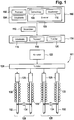
- the Figure 1 shows a system comprising a control unit 100 and a continuous casting plant 101.
- a converter 122 is used to provide liquid material.
- the material is steel, so that the converter can take up liquid steel.
- the liquid steel can be fed into a distributor 124 via a pan (not shown in more detail), the distributor then having the function of distributing the liquid steel to the individual strands in the case of the multi-strand system shown.
- the liquid steel is introduced from the distributor 124 into the molds 126 via pouring pipes, which are likewise not shown in detail.
- the molds are cooled on their insides, so that the liquid steel solidifies on the insides.
- the mold is moved in an oscillating manner in order to prevent the steel from sticking to the cooled walls and to support the transport process.
- the strand now has that solidified shell a few centimeters thick, while the majority of the cross-section is still liquid.
- the strand is then cooled again and, supported by rollers 130, moved on.
- Figure 1 a set of four strands in total. Also in the example of the continuous casting plant from Figure 1 The two left strands form a pair and the two right strands also form a pair 128. The pair formation is given because a cutting device 134 is provided for each pair 128 of strands, which is provided for dividing the strand to obtain individual slabs 132 . This leads to the technical restriction that the slabs 132 of a strand pair 128 inevitably always have to have identical lengths.
- control parameters that are important for the products are controlled, ie the width of the molds 126 and the slab lengths to be produced by the cutting devices 134, as well as the continuous casting process, ie the movement of the strand, the pouring of the molten steel into the ladle into the distributor, the movement of the mold 126 etc. by a continuous casting program which is transmitted to the external system by means of the interface and is contained in the memory 120 of a control computer 114.
- the control computer 114 also has a processor 118 that is capable of what is contained in the memory 120 Execute a continuous casting program in order to control the continuous casting plant.
- the control computer 114 also has an interface 116 via which the control computer can receive control data 112 from a control unit 100.
- the control data 112 determine the slabs that are to be produced by the continuous casting plant.
- the control data determine the sequence and distribution of the slabs on the individual strands, as well as the geometric dimensions of the slabs in detail.
- the control unit 100 has a processor 102, an interface 104 and a memory 106.
- the interface 104 is used for communication with the interface 116.
- the memory 106 comprises various casting orders 108 and instructions 110 the control unit 100 is able to perform the following in Figure 2 to carry out the described method with respect to the casting orders 108.
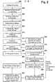
- the method for controlling the continuous casting plant 101 begins in step 200 of FIG Figure 2 with the receipt of the casting orders 108, which are then contained in the memory 106 of the control unit 100.
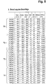
- various casting orders with the designation order 1, order 2, ... order 7 are specified, for example, order 1 specifies a required quantity of 50 t with a rolling width of 520 mm, with tolerances relating to the rolling width of a minimum of 490 mm and Maximum 550 mm are specified. Since the casting orders are all given for the goal of producing steel coils, an associated minimum and maximum KIM weight is also specified for each of the casting orders.
- the minimum KIM weight is 15 kg / mm and the maximum KIM weight is 20 kg / mm.
- an associated semi-finished product weight of at least 7959 kg and a maximum semi-finished product weight of a maximum of 10192 kg can be calculated with regard to the roll width of 520 mm, whereby an output of 98% is taken into account here (for example 520 x 15 / 0.98).
- a slab from which a coil with the aforementioned details of the rolling width and the KIM weights will have a total weight of between at least 7959 kg and a maximum of 10192 kg.
- Each order therefore specifies a required quantity of material (in the example of the Figure 3 , Order 1 with 50,000 kg) and an associated slab width, in the example of Figure 3 with order 1 520 mm and tolerance specifications with regard to the widths, again in the example of Figure 3 for order 1, the minimum and maximum KIM weight and the resulting slab weights.
- a set of slabs to be cast with associated slab weights and slab widths is determined for each of the orders from the respective required quantities and the respective slab widths.
- Minimum and maximum weight of semi-finished products (slab weight) determined for each order an average value can now be determined, which in Figure 3 with regard to order 1 corresponds to an amount of 9076 kg.
- the amount that has to be produced with regard to order 1 is even clearly exceeded, namely 54456 kg are achieved by these six slabs at the assumed average slab weight.
- the slabs are then sorted in step 204 to obtain a basic sequence.
- the sorting takes place according to a sorting criterion, the sorting criterion including the width of the slab.
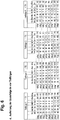
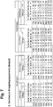
- the rolling widths carried out there are now listed and sorted individually for each order, starting from the largest rolling width to the smallest rolling width, with the corresponding associated result in Figure 5 can be seen.
- Order 2 with the largest rolling width of 650 appears with the number of specified slabs of three initially in the top three lines of the basic sequence of Figure 5 , followed by the four slabs relating to order 6 with a rolling width of 600 mm, then followed by the five slabs from order 5 with a rolling width of 550 mm, etc.
- the in Figure 5 The sequence of the sorted slabs to be cast shown here is referred to below as the “sorted basic sequence of slabs to be cast”.
- the sorted basic sequence becomes the Figure 5 partitioned into a number of subsequences corresponding to the number of molds 126 of the Figure 1 corresponds to.
- the table is now partitioned Figure 5 in four partial sequences.
- Each partial sequence comprises an identical number of slabs to be cast.
- the table of Figure 5 a directly connected set of slabs to be cast is selected and defined as partial sequence 1.
- Partial sequence 1 and all other partial sequences include exactly eight slabs to be cast. These are marked with T1 in the following. This is followed by the next eight slabs to be cast on the table of Figure 5 which are marked as T2. This is followed by T3 and then T4, each comprising eight slabs to be cast.
- T1, T2, T3 and T4 are in the Figure 6 shown.
- each of the partial sequences is uniquely assigned to one of the strands, i.e. to one of the molds 126, the allocation being made in such a way that the average slab width going from the inner strands to the outer strands the slabs to be cast determined in the respective partial sequence steadily decreases.
- the two inner strands have the partial sequence 1 and partial sequence 2 with the large slab widths and the two outer strands have the partial sequences 3 and 4 with the smaller slab widths.
- the slab widths of the slabs of the partial sequences to be cast are adapted for each of the partial sequences, taking into account the tolerance information.
- the aim is to keep the jumps in width between consecutive slabs to be cast in a partial sequence in a range that corresponds to the permissible specifications for the continuous casting plant.
- the maximum permissible difference in width between two consecutive slabs is referred to as the "grade rule", with the Figure 1 this grade rule is assumed to be a maximum of 25 mm.
- main strand 1 including the sub-strings 1 and 2 with the sub-strings 3 and 2 will be discussed in the following, with calculations relating to the second main branch including sub-strings 3 and 4 with the sub-strings 1 and 4 being able to be set in a similar manner.
- this is a so-called twin casting system, in which only one common cutting system 134 is available for a pair of the strands 128, it must be ensured that the slabs of the parallel sub-strands 128, i.e. the slabs in the Sub-strands 1 and 2 have identical lengths. However, this has not yet been taken into account in the previous adjustments. For this reason, the slab lengths are adapted, which is outlined in general in step 212 and specifically in steps 214-216. After the slab widths have now been adjusted in step 210, a corresponding associated minimum and maximum length of the slab can be calculated for a given strand width from the respective lower and upper limit of the slab weight.
- the adjusted strand width 500 mm results in a minimum slab length of 7849 mm and a maximum slab length of 10051 mm.
- These calculations can now be carried out for all slabs specified in the partial sequences. This corresponds to step 214 of FIG Figure 2 .
- an average value is determined with regard to the two minimum and maximum lengths of the slabs, and from this an average length is calculated for both slabs.
- sub-strand 1 and partial sequence T3 results in an average slab length of 8757 mm, which is identical to sub-strand 2 (T2) and the first slab, order 5. Due to the different strand widths of 500 mm and 550 mm with regard to this first line there are correspondingly different associated slab weights of 8880 kg and 9768 kg.
- step 218 with the adaptation of the slab weights to the actual amount of liquid steel available in a converter. If one adds up in the Figure 8 the slab weights resulting from the slab lengths determined in step 216, then taking into account all sub-strands (including sub-strands 3 and 4, not shown), a total weight may result that does not optimally take into account the amount of liquid steel that is supplied with one or more converters To be available. For example, if the total weight is 275 t, but if only 270 t can be made available with a liquid steel converter, then the slab weight or length is changed evenly across all slabs of all sub-strands until the total weight obtained from this corresponds to the desired target weight .
- the corresponding tolerances with regard to minimum and maximum slab width or minimum and maximum slab length must be taken into account.
- this can be implemented in step 218, the adjustment of the slab weights, in such a way that a quotient of the resulting total weight and target weight is determined across all slabs of all sub-strands, with the change in the slab weight or slab length of each individual slab being a multiplication of the slab weight or the slab length with this coefficient.
- the result in this regard is in the Figure 9 shown as an example.
- the total weights of the lower strands have increased here in order to optimally achieve the target weight.
- step 218 the casting times are optimized in step 220, the details of step 220 being outlined in steps 222-232.
- the aim is to increase the strand width while at the same time shortening the strand length in such a way that the weight is retained and no tolerance violation occurs.
- the steps of optimizing the casting times are detailed in Figure 2 with steps 222 to 232.
- the value Q1_i is first determined in step 222, with i indicating the respective pair of parallel slabs with respect to a pair of billets.
- i would specify the first line for the pair of slabs Order 1 and Order 5 with regard to substrings 1 and 2.
- order 1 the quotient of the maximum width (550 mm) and the width of the current slab (500 mm) is calculated and saved.
- order 5 the quotient with regard to the first line or the first slab for lower strand 1, order 5 is calculated as 580 mm by 550 mm.
- step 224 a further quotient is calculated in step 224 for the slabs of this pair of slabs, although there is no "pre-slab" here, since those specified in the first line Slabs are the first slabs. In this respect, Q2 does not play a role here.
- sub-strand 1 and sub-strand 2 are now common (since parallel slab) uses the smallest value of the thus calculated quotient for the first row (step 230). This smallest quotient is then used to multiply the width of the current slab in row 1 for sub-strand 1 and sub-strand 2, and the length of the current slab is divided in each case (step 232).
- steps 222 to 232 can initially be carried out iteratively for all slabs of a pair of bars and for all bars, this process being repeated several times after these steps have been completed it can be repeated until either the width of the slabs is no longer changed or a certain number of iterations has been reached or exceeded.
- the result is slabs that are to be cast in this way, which are optimized with regard to the casting time in that the strand width is increased within the tolerances without any tolerance violations occurring.
- the method finally ends in step 234 with the transmission of the control data 112 to the continuous casting plant using the interfaces 104 and 116.
- the control data contain information relating to the order in which the slabs are produced with the corresponding calculated width and length should.
- the control computer 114 can then control the control system in such a way that the corresponding production of the slabs takes place.
Landscapes
- Engineering & Computer Science (AREA)
- Mechanical Engineering (AREA)
- Continuous Casting (AREA)
- General Factory Administration (AREA)
Priority Applications (1)
| Application Number | Priority Date | Filing Date | Title |
|---|---|---|---|
| PL19156792T PL3530374T3 (pl) | 2018-02-21 | 2019-02-12 | Sposób sterowania urządzeniem do odlewania ciągłego |
Applications Claiming Priority (1)
| Application Number | Priority Date | Filing Date | Title |
|---|---|---|---|
| DE102018202651.3A DE102018202651B3 (de) | 2018-02-21 | 2018-02-21 | Verfahren zur Steuerung einer Stranggussanlage |
Publications (2)
| Publication Number | Publication Date |
|---|---|
| EP3530374A1 EP3530374A1 (de) | 2019-08-28 |
| EP3530374B1 true EP3530374B1 (de) | 2021-03-31 |
Family
ID=65433519
Family Applications (1)
| Application Number | Title | Priority Date | Filing Date |
|---|---|---|---|
| EP19156792.4A Active EP3530374B1 (de) | 2018-02-21 | 2019-02-12 | Verfahren zur steuerung einer stranggussanlage |
Country Status (5)
| Country | Link |
|---|---|
| US (1) | US11045868B2 (pl) |
| EP (1) | EP3530374B1 (pl) |
| DE (1) | DE102018202651B3 (pl) |
| ES (1) | ES2882000T3 (pl) |
| PL (1) | PL3530374T3 (pl) |
Families Citing this family (3)
| Publication number | Priority date | Publication date | Assignee | Title |
|---|---|---|---|---|
| EP3714999B1 (de) * | 2019-03-28 | 2022-09-28 | Primetals Technologies Germany GmbH | Ermittlung einer anstellung eines walzgerüsts |
| CN112207245B (zh) * | 2020-09-27 | 2022-03-15 | 安徽工业大学 | 一种连铸过程高低频数据与切割铸坯号匹配的方法 |
| JP2023151904A (ja) * | 2022-04-01 | 2023-10-16 | 日鉄エンジニアリング株式会社 | 試料片回収装置及び試料片回収方法 |
Family Cites Families (4)
| Publication number | Priority date | Publication date | Assignee | Title |
|---|---|---|---|---|
| DE19741131C2 (de) | 1997-09-15 | 2001-06-28 | Sms Demag Ag | Stranggießkokille |
| JP2000317583A (ja) | 1999-05-07 | 2000-11-21 | Nippon Steel Corp | ビレット連続鋳造設備における鋳造制御方法 |
| DE10047381A1 (de) * | 2000-09-25 | 2002-04-18 | Siemens Ag | Verfahren und Vorrichtung zum Betreiben einer Anlage der Grundstoffindustrie |
| DE10339766A1 (de) | 2003-08-27 | 2005-04-07 | Siemens Ag | Verfahren und Einrichtung zur Steuerung einer Anlage zur Herstellung von Stahl |
-
2018
- 2018-02-21 DE DE102018202651.3A patent/DE102018202651B3/de active Active
-
2019
- 2019-02-12 ES ES19156792T patent/ES2882000T3/es active Active
- 2019-02-12 PL PL19156792T patent/PL3530374T3/pl unknown
- 2019-02-12 EP EP19156792.4A patent/EP3530374B1/de active Active
- 2019-02-15 US US16/277,229 patent/US11045868B2/en active Active
Non-Patent Citations (1)
| Title |
|---|
| None * |
Also Published As
| Publication number | Publication date |
|---|---|
| ES2882000T3 (es) | 2021-11-30 |
| US20190255602A1 (en) | 2019-08-22 |
| DE102018202651B3 (de) | 2019-05-29 |
| US11045868B2 (en) | 2021-06-29 |
| PL3530374T3 (pl) | 2021-10-25 |
| EP3530374A1 (de) | 2019-08-28 |
Similar Documents
| Publication | Publication Date | Title |
|---|---|---|
| EP3530374B1 (de) | Verfahren zur steuerung einer stranggussanlage | |
| DE102010032185A1 (de) | Verfahren und Vorrichtung zum Koordinieren von zwei aufeinanderfolgenden Herstellungsstufen eines Produktionsprozesses | |
| DE69507729T2 (de) | Verfahren zur Herstellung von Bandstahl, ausgehend von dünnen Bramen, und entsprechende Anlage | |
| EP2346631B1 (de) | Verfahren und vorrichtung zur steuerung der erstarrung eines giessstranges in einer stranggiessanlage beim anfahren des giessprozesses | |
| EP2588257B1 (de) | Betriebsverfahren für ein walzwerk zum walzen von flachem walzgut mit walzenverschleissprognose | |
| EP1200216B1 (de) | Verfahren und einrichtung zum herstellen eines stranges aus metall | |
| EP1324845B1 (de) | Verfahren zum betreiben einer anlage der grundstoffindustrie | |
| EP2340133B1 (de) | Verfahren zum einstellen einer antriebslast für eine mehrzahl an antrieben einer walzstrasse zum walzen von walzgut, steuer- und/oder regeleinrichtung, speichermedium, programmcode und walzanlage | |
| DE1943556A1 (de) | Verfahren und Einrichtung zur Beeinflussung des Walzablaufs eines Walzgutes in einer Walzanlage | |
| EP2906369B1 (de) | Breitenbeeinflussung eines bandförmigen walzguts | |
| EP2272605A1 (de) | Regelverfahren für den Gießspiegel einer Stranggießkokille | |
| EP3733323B1 (de) | Verfahren und stranggiessanlage zum giessen eines giessstrangs | |
| DE102020209794A1 (de) | Verfahren zur Steuerung oder Regelung der Temperatur eines Gießstrangs in einer Stranggießanlage | |
| EP3700694B1 (de) | Verfahren zum trennen eines giessstranges oder zwischenbandes mittels einer schere | |
| EP1107841B1 (de) | Giesswalzanlage, insbesondere dünnbrammengiesswalzanlage | |
| EP4133345B1 (de) | Verfahren zur dynamischen produktionsplanung bei strangguss anlagen | |
| WO1998049354A1 (de) | Verfahren und einrichtung zur kühlung von metallen in einem hüttenwerk | |
| EP3831511A1 (de) | Verfahren und computersystem zur vorhersage einer schrumpfung eines gegossenen metallproduktes | |
| EP0036852A1 (de) | Verfahren zum Teilen von Materialsträngen | |
| DE102023211928A1 (de) | Verfahren zum Betreiben eines Walzwerks | |
| EP3944910A1 (de) | Verfahren zur herstellung eines giessstrangs in einer stranggiessanlage | |
| DE102010010551B4 (de) | Verfahren und Vorrichtung zum Koordinieren von zwei aufeinanderfolgenden Herstellungsstufen eines Produktionsprozesses | |
| EP4501489A1 (de) | Rollenanordnung und optimierungsverfahren | |
| DE102021205910A1 (de) | Verfahren, System und Computerprogramm zur Planung einer Produktion in einer aus mehreren separaten aufeinanderfolgenden Anlagenteilen bestehenden Produktionsanlage, insbesondere einer metallurgischen Produktionsanlage zur Erzeugung von Industriegütern wie metallischem Halbzeug und/oder metallischen Endprodukten | |
| EP2755134A1 (de) | Steuerung einer technischen Anlage mit CPU und GPU |
Legal Events
| Date | Code | Title | Description |
|---|---|---|---|
| PUAI | Public reference made under article 153(3) epc to a published international application that has entered the european phase |
Free format text: ORIGINAL CODE: 0009012 |
|
| STAA | Information on the status of an ep patent application or granted ep patent |
Free format text: STATUS: THE APPLICATION HAS BEEN PUBLISHED |
|
| AK | Designated contracting states |
Kind code of ref document: A1 Designated state(s): AL AT BE BG CH CY CZ DE DK EE ES FI FR GB GR HR HU IE IS IT LI LT LU LV MC MK MT NL NO PL PT RO RS SE SI SK SM TR |
|
| AX | Request for extension of the european patent |
Extension state: BA ME |
|
| STAA | Information on the status of an ep patent application or granted ep patent |
Free format text: STATUS: REQUEST FOR EXAMINATION WAS MADE |
|
| 17P | Request for examination filed |
Effective date: 20200107 |
|
| RBV | Designated contracting states (corrected) |
Designated state(s): AL AT BE BG CH CY CZ DE DK EE ES FI FR GB GR HR HU IE IS IT LI LT LU LV MC MK MT NL NO PL PT RO RS SE SI SK SM TR |
|
| GRAP | Despatch of communication of intention to grant a patent |
Free format text: ORIGINAL CODE: EPIDOSNIGR1 |
|
| STAA | Information on the status of an ep patent application or granted ep patent |
Free format text: STATUS: GRANT OF PATENT IS INTENDED |
|
| INTG | Intention to grant announced |
Effective date: 20201007 |
|
| RBV | Designated contracting states (corrected) |
Designated state(s): AL AT BE BG CH CY CZ DK EE ES FI FR GB GR HR HU IE IS IT LI LT LU LV MC MK MT NL NO PL PT RO RS SE SI SK SM TR |
|
| REG | Reference to a national code |
Ref country code: DE Ref legal event code: R108 |
|
| GRAS | Grant fee paid |
Free format text: ORIGINAL CODE: EPIDOSNIGR3 |
|
| GRAA | (expected) grant |
Free format text: ORIGINAL CODE: 0009210 |
|
| STAA | Information on the status of an ep patent application or granted ep patent |
Free format text: STATUS: THE PATENT HAS BEEN GRANTED |
|
| RAP1 | Party data changed (applicant data changed or rights of an application transferred) |
Owner name: THYSSENKRUPP HOHENLIMBURG GMBH Owner name: THYSSENKRUPP AG |
|
| AK | Designated contracting states |
Kind code of ref document: B1 Designated state(s): AL AT BE BG CH CY CZ DK EE ES FI FR GB GR HR HU IE IS IT LI LT LU LV MC MK MT NL NO PL PT RO RS SE SI SK SM TR |
|
| REG | Reference to a national code |
Ref country code: GB Ref legal event code: FG4D Free format text: NOT ENGLISH Ref country code: CH Ref legal event code: EP |
|
| REG | Reference to a national code |
Ref country code: AT Ref legal event code: REF Ref document number: 1376371 Country of ref document: AT Kind code of ref document: T Effective date: 20210415 |
|
| REG | Reference to a national code |
Ref country code: IE Ref legal event code: FG4D Free format text: LANGUAGE OF EP DOCUMENT: GERMAN |
|
| REG | Reference to a national code |
Ref country code: FI Ref legal event code: FGE |
|
| REG | Reference to a national code |
Ref country code: NL Ref legal event code: FP |
|
| REG | Reference to a national code |
Ref country code: SE Ref legal event code: TRGR |
|
| REG | Reference to a national code |
Ref country code: LT Ref legal event code: MG9D |
|
| PG25 | Lapsed in a contracting state [announced via postgrant information from national office to epo] |
Ref country code: BG Free format text: LAPSE BECAUSE OF FAILURE TO SUBMIT A TRANSLATION OF THE DESCRIPTION OR TO PAY THE FEE WITHIN THE PRESCRIBED TIME-LIMIT Effective date: 20210630 Ref country code: HR Free format text: LAPSE BECAUSE OF FAILURE TO SUBMIT A TRANSLATION OF THE DESCRIPTION OR TO PAY THE FEE WITHIN THE PRESCRIBED TIME-LIMIT Effective date: 20210331 Ref country code: NO Free format text: LAPSE BECAUSE OF FAILURE TO SUBMIT A TRANSLATION OF THE DESCRIPTION OR TO PAY THE FEE WITHIN THE PRESCRIBED TIME-LIMIT Effective date: 20210630 |
|
| PG25 | Lapsed in a contracting state [announced via postgrant information from national office to epo] |
Ref country code: LV Free format text: LAPSE BECAUSE OF FAILURE TO SUBMIT A TRANSLATION OF THE DESCRIPTION OR TO PAY THE FEE WITHIN THE PRESCRIBED TIME-LIMIT Effective date: 20210331 Ref country code: RS Free format text: LAPSE BECAUSE OF FAILURE TO SUBMIT A TRANSLATION OF THE DESCRIPTION OR TO PAY THE FEE WITHIN THE PRESCRIBED TIME-LIMIT Effective date: 20210331 |
|
| REG | Reference to a national code |
Ref country code: SK Ref legal event code: T3 Ref document number: E 37594 Country of ref document: SK |
|
| PG25 | Lapsed in a contracting state [announced via postgrant information from national office to epo] |
Ref country code: SM Free format text: LAPSE BECAUSE OF FAILURE TO SUBMIT A TRANSLATION OF THE DESCRIPTION OR TO PAY THE FEE WITHIN THE PRESCRIBED TIME-LIMIT Effective date: 20210331 Ref country code: LT Free format text: LAPSE BECAUSE OF FAILURE TO SUBMIT A TRANSLATION OF THE DESCRIPTION OR TO PAY THE FEE WITHIN THE PRESCRIBED TIME-LIMIT Effective date: 20210331 Ref country code: EE Free format text: LAPSE BECAUSE OF FAILURE TO SUBMIT A TRANSLATION OF THE DESCRIPTION OR TO PAY THE FEE WITHIN THE PRESCRIBED TIME-LIMIT Effective date: 20210331 |
|
| PG25 | Lapsed in a contracting state [announced via postgrant information from national office to epo] |
Ref country code: RO Free format text: LAPSE BECAUSE OF FAILURE TO SUBMIT A TRANSLATION OF THE DESCRIPTION OR TO PAY THE FEE WITHIN THE PRESCRIBED TIME-LIMIT Effective date: 20210331 Ref country code: PT Free format text: LAPSE BECAUSE OF FAILURE TO SUBMIT A TRANSLATION OF THE DESCRIPTION OR TO PAY THE FEE WITHIN THE PRESCRIBED TIME-LIMIT Effective date: 20210802 Ref country code: IS Free format text: LAPSE BECAUSE OF FAILURE TO SUBMIT A TRANSLATION OF THE DESCRIPTION OR TO PAY THE FEE WITHIN THE PRESCRIBED TIME-LIMIT Effective date: 20210731 |
|
| REG | Reference to a national code |
Ref country code: ES Ref legal event code: FG2A Ref document number: 2882000 Country of ref document: ES Kind code of ref document: T3 Effective date: 20211130 |
|
| PG25 | Lapsed in a contracting state [announced via postgrant information from national office to epo] |
Ref country code: DK Free format text: LAPSE BECAUSE OF FAILURE TO SUBMIT A TRANSLATION OF THE DESCRIPTION OR TO PAY THE FEE WITHIN THE PRESCRIBED TIME-LIMIT Effective date: 20210331 Ref country code: AL Free format text: LAPSE BECAUSE OF FAILURE TO SUBMIT A TRANSLATION OF THE DESCRIPTION OR TO PAY THE FEE WITHIN THE PRESCRIBED TIME-LIMIT Effective date: 20210331 |
|
| PLBE | No opposition filed within time limit |
Free format text: ORIGINAL CODE: 0009261 |
|
| STAA | Information on the status of an ep patent application or granted ep patent |
Free format text: STATUS: NO OPPOSITION FILED WITHIN TIME LIMIT |
|
| 26N | No opposition filed |
Effective date: 20220104 |
|
| PG25 | Lapsed in a contracting state [announced via postgrant information from national office to epo] |
Ref country code: IS Free format text: LAPSE BECAUSE OF FAILURE TO SUBMIT A TRANSLATION OF THE DESCRIPTION OR TO PAY THE FEE WITHIN THE PRESCRIBED TIME-LIMIT Effective date: 20210731 |
|
| PG25 | Lapsed in a contracting state [announced via postgrant information from national office to epo] |
Ref country code: MC Free format text: LAPSE BECAUSE OF FAILURE TO SUBMIT A TRANSLATION OF THE DESCRIPTION OR TO PAY THE FEE WITHIN THE PRESCRIBED TIME-LIMIT Effective date: 20210331 |
|
| REG | Reference to a national code |
Ref country code: CH Ref legal event code: PL |
|
| PG25 | Lapsed in a contracting state [announced via postgrant information from national office to epo] |
Ref country code: LU Free format text: LAPSE BECAUSE OF NON-PAYMENT OF DUE FEES Effective date: 20220212 |
|
| PG25 | Lapsed in a contracting state [announced via postgrant information from national office to epo] |
Ref country code: LI Free format text: LAPSE BECAUSE OF NON-PAYMENT OF DUE FEES Effective date: 20220228 Ref country code: IE Free format text: LAPSE BECAUSE OF NON-PAYMENT OF DUE FEES Effective date: 20220212 Ref country code: CH Free format text: LAPSE BECAUSE OF NON-PAYMENT OF DUE FEES Effective date: 20220228 |
|
| P01 | Opt-out of the competence of the unified patent court (upc) registered |
Effective date: 20230515 |
|
| PG25 | Lapsed in a contracting state [announced via postgrant information from national office to epo] |
Ref country code: MK Free format text: LAPSE BECAUSE OF FAILURE TO SUBMIT A TRANSLATION OF THE DESCRIPTION OR TO PAY THE FEE WITHIN THE PRESCRIBED TIME-LIMIT Effective date: 20210331 Ref country code: CY Free format text: LAPSE BECAUSE OF FAILURE TO SUBMIT A TRANSLATION OF THE DESCRIPTION OR TO PAY THE FEE WITHIN THE PRESCRIBED TIME-LIMIT Effective date: 20210331 |
|
| PG25 | Lapsed in a contracting state [announced via postgrant information from national office to epo] |
Ref country code: HU Free format text: LAPSE BECAUSE OF FAILURE TO SUBMIT A TRANSLATION OF THE DESCRIPTION OR TO PAY THE FEE WITHIN THE PRESCRIBED TIME-LIMIT; INVALID AB INITIO Effective date: 20190212 |
|
| PG25 | Lapsed in a contracting state [announced via postgrant information from national office to epo] |
Ref country code: MT Free format text: LAPSE BECAUSE OF FAILURE TO SUBMIT A TRANSLATION OF THE DESCRIPTION OR TO PAY THE FEE WITHIN THE PRESCRIBED TIME-LIMIT Effective date: 20210331 |
|
| PG25 | Lapsed in a contracting state [announced via postgrant information from national office to epo] |
Ref country code: GR Free format text: LAPSE BECAUSE OF NON-PAYMENT OF DUE FEES Effective date: 20210331 |
|
| PG25 | Lapsed in a contracting state [announced via postgrant information from national office to epo] |
Ref country code: GR Free format text: LAPSE BECAUSE OF NON-PAYMENT OF DUE FEES Effective date: 20210331 |
|
| PGFP | Annual fee paid to national office [announced via postgrant information from national office to epo] |
Ref country code: NL Payment date: 20250218 Year of fee payment: 7 |
|
| PGFP | Annual fee paid to national office [announced via postgrant information from national office to epo] |
Ref country code: FI Payment date: 20250220 Year of fee payment: 7 |
|
| PGFP | Annual fee paid to national office [announced via postgrant information from national office to epo] |
Ref country code: SE Payment date: 20250218 Year of fee payment: 7 |
|
| PGFP | Annual fee paid to national office [announced via postgrant information from national office to epo] |
Ref country code: BE Payment date: 20250218 Year of fee payment: 7 Ref country code: AT Payment date: 20250219 Year of fee payment: 7 |
|
| PGFP | Annual fee paid to national office [announced via postgrant information from national office to epo] |
Ref country code: FR Payment date: 20250224 Year of fee payment: 7 Ref country code: PL Payment date: 20250131 Year of fee payment: 7 Ref country code: CZ Payment date: 20250207 Year of fee payment: 7 |
|
| PGFP | Annual fee paid to national office [announced via postgrant information from national office to epo] |
Ref country code: IT Payment date: 20250224 Year of fee payment: 7 Ref country code: GB Payment date: 20250220 Year of fee payment: 7 Ref country code: SK Payment date: 20250205 Year of fee payment: 7 |
|
| PGFP | Annual fee paid to national office [announced via postgrant information from national office to epo] |
Ref country code: TR Payment date: 20250204 Year of fee payment: 7 |
|
| PGFP | Annual fee paid to national office [announced via postgrant information from national office to epo] |
Ref country code: ES Payment date: 20250331 Year of fee payment: 7 |