EP3529814B1 - Elektromagnetisches stellglied - Google Patents
Elektromagnetisches stellglied Download PDFInfo
- Publication number
- EP3529814B1 EP3529814B1 EP17757780.6A EP17757780A EP3529814B1 EP 3529814 B1 EP3529814 B1 EP 3529814B1 EP 17757780 A EP17757780 A EP 17757780A EP 3529814 B1 EP3529814 B1 EP 3529814B1
- Authority
- EP
- European Patent Office
- Prior art keywords
- cover
- pole tube
- armature
- electromagnetic actuator
- pole
- Prior art date
- Legal status (The legal status is an assumption and is not a legal conclusion. Google has not performed a legal analysis and makes no representation as to the accuracy of the status listed.)
- Active
Links
Images


Classifications
-
- H—ELECTRICITY
- H01—ELECTRIC ELEMENTS
- H01F—MAGNETS; INDUCTANCES; TRANSFORMERS; SELECTION OF MATERIALS FOR THEIR MAGNETIC PROPERTIES
- H01F7/00—Magnets
- H01F7/06—Electromagnets; Actuators including electromagnets
- H01F7/08—Electromagnets; Actuators including electromagnets with armatures
- H01F7/127—Assembling
-
- F—MECHANICAL ENGINEERING; LIGHTING; HEATING; WEAPONS; BLASTING
- F16—ENGINEERING ELEMENTS AND UNITS; GENERAL MEASURES FOR PRODUCING AND MAINTAINING EFFECTIVE FUNCTIONING OF MACHINES OR INSTALLATIONS; THERMAL INSULATION IN GENERAL
- F16K—VALVES; TAPS; COCKS; ACTUATING-FLOATS; DEVICES FOR VENTING OR AERATING
- F16K31/00—Actuating devices; Operating means; Releasing devices
- F16K31/02—Actuating devices; Operating means; Releasing devices electric; magnetic
- F16K31/06—Actuating devices; Operating means; Releasing devices electric; magnetic using a magnet, e.g. diaphragm valves, cutting off by means of a liquid
- F16K31/0675—Electromagnet aspects, e.g. electric supply therefor
-
- H—ELECTRICITY
- H01—ELECTRIC ELEMENTS
- H01F—MAGNETS; INDUCTANCES; TRANSFORMERS; SELECTION OF MATERIALS FOR THEIR MAGNETIC PROPERTIES
- H01F7/00—Magnets
- H01F7/06—Electromagnets; Actuators including electromagnets
- H01F7/08—Electromagnets; Actuators including electromagnets with armatures
- H01F7/081—Magnetic constructions
-
- H—ELECTRICITY
- H01—ELECTRIC ELEMENTS
- H01F—MAGNETS; INDUCTANCES; TRANSFORMERS; SELECTION OF MATERIALS FOR THEIR MAGNETIC PROPERTIES
- H01F7/00—Magnets
- H01F7/06—Electromagnets; Actuators including electromagnets
- H01F7/08—Electromagnets; Actuators including electromagnets with armatures
- H01F7/16—Rectilinearly-movable armatures
- H01F7/1607—Armatures entering the winding
Definitions
- the invention relates to an electromagnetic actuator according to the preamble of claim 1.
- the invention has the advantage that material and costs can be saved in that the cover has the pole disk and yet is formed in one piece. Cost savings result here from the reduction in investments in production facilities and in particular from the fact that the cover together with the pole disc can be attached to the actuator in just a single operation. Functional integration also takes place in an advantageous manner, since the function of the pole disc, namely enabling the magnetic flux and thus closing the magnetic circuit, and the function of the cover, namely in particular the axial delimitation of the armature space, are performed using a single component. Nevertheless, a flexible fastening of the cover, in particular to an actuator housing, and a flexible arrangement of an electrical connection for the coil on the cover are made possible.
- the cover is cup-shaped with a cover casing and a cover base, the cover casing and/or the cover base bearing or bearing against a pole tube delimiting the armature space. Consequently, the pole tube delimits the armature space in the radial direction, ie perpendicular to the longitudinal axis, while the cover delimits the armature space on an axial end side.
- the pole tube is used on the one hand to support and guide the armature, and on the other hand the magnetic flux that can be generated by the coil is also conducted through the pole tube.
- the pole tube has a first section surrounded by the coil and a second section surrounded by the cover casing, the outer diameter of the second section being 10% to 30%, in particular 20%, larger than the outer diameter of the first section.
- the cover base has at least one projection designed as an anchor stop.
- several projections can be present. This can in particular prevent the so-called magnetic sticking of the armature to the lid, since the contact surface to the lid is comparatively small when the armature comes into contact with the lid and there is a gap between the armature and the lid base due to the formation of the projection.
- the cover jacket and/or the cover base can have at least one groove for venting the armature space.
- at least one groove is provided, which extends over the cover base and the cover jacket. Consequently, despite the integration of the pole disk in the cover, the armature space can be vented through the groove, or hydraulic fluid can be pumped out of or into the armature space.
- the cover base is at a distance from the pole tube. In this way, it can be ensured in particular that an axial fastening force does not have a damaging effect on any V-groove provided in the pole tube.
- Such a V-shaped groove is implemented in one-piece pole tubes to provide magnetic separation.
- a flux disk which delimits the armature space and is firmly connected to the pole tube, in particular crimped or pressed.
- a flux disk can be provided in particular at the axial end of the armature space opposite the pole disk and can also be used to conduct the magnetic flux and thus to provide a magnetic circuit.
- the cover jacket has at least one projection on the outside, the projection being supported on an actuator housing. This can ensure that when the projections come to rest on the actuator housing, an axial spacing is provided between the cover base and the pole tube.
- the cover includes a recess for arranging an electrical plug for energizing the coil.
- the recess can in particular be designed as a segment of a circle, so that a segment of a circle is cut out of an otherwise circular cover, so that an electrical plug can be guided through it or can be arranged on it.
- the cover is produced by powder metallurgy, in particular sintered. As a result, materials with favorable magnetic properties can be used.
- grooves or stop areas for the armature or also a recess for a plug passage can be produced on the cover in a particularly simple and cost-effective manner with little expenditure of time and money.
- a pressure control valve with a valve element for conducting and regulating the pressure of a working medium, such as oil, being actuatable by means of the actuating element.
- a pressure control valve can be used in particular in a passenger car automatic transmission for hydraulically actuating clutches to change gears.
- the actuator 10 comprises an essentially tubular housing 12, which can be produced in particular from a rolled and linked sheet metal component.
- the housing 12 runs essentially rotationally symmetrically about a longitudinal axis 14 .
- the magnetic coil 18 can be supplied with power using a power connection that is not shown in detail.
- a pole tube 20 is provided inside the coil body 16 .
- the pole tube 20 has a first surrounded by the coil 18 cylindrical portion 21 and a second at the right end portion of the figure 1 provided Section 23.
- the first section 21 has an outer diameter D1, while the second section 23 has an outer diameter D2, with D2 being approximately 20% larger than D1.
- the pole tube 20 has an overall approximately V-shaped recess 24 on its outer circumference 22 in the area of the section 21 .
- the recess 24 is in this respect designed as a V-groove and serves to prevent a magnetic short circuit.
- the pole tube 20 has a cylindrical, stepped inner recess 26 . This runs from in the figure 1 shown right end of the pole tube up to a magnetic yoke 28 provided in the left end area, which has a through-opening 30 includes.
- the inner recess 26 is delimited at a first axial end by the yoke 28, in the radial direction by the pole tube 20 and at a second axial end by a cover 32.
- the cylindrical recess 26 forms an armature space 34 in which an armature 36 is slidably mounted.
- a bolt 44 is pressed into a central recess 42 of the armature 36 .
- the actuating element 46 is constructed in two parts and comprises a plunger 48 guided through the through-opening 30 and a separating piece 50 pressed onto it, to which the bolt 44 can be brought into contact.
- the actuating element 46 can in particular be designed to actuate a valve element, not shown in detail, of a pressure control valve.
- An annular flux disk 40 is placed on a circular-cylindrical free end 38 of the yoke 28 designed as a projection. The flux disk 40 serves to conduct a magnetic flux generated by the magnet coil 18 .
- the cover 32 is pot-shaped with a cover jacket 52 and a cover base 54 .
- the inner peripheral surface 55 of the cover jacket 52 rests against the outer peripheral surface 57 of the second section 23 of the pole tube 20 .
- the cover base 54 rests axially on the second section 23 of the pole tube 20 .
- the cover base 54 has a number of projections.
- a ventilation groove 58 is also provided in the cover 32 and extends from the cover base 54 over the cover jacket 52 .
- a segment of a circle is recessed from the otherwise circular-cylindrical cover 32, so that a section 60 of the cover jacket 52 is formed as a straight line.
- the operation of the actuator 10 is then as follows: If a current is applied to the magnetic coil 18, this results in a magnetic flux, with a magnetic circuit being formed between the pole tube 20, the flux disc 40 and the cover 32. The cover 32 is consequently magnetic at least in sections and thus forms a pole disk 61 .
- the magnetic flux through the magnetic circuit results in a magnetic force on the armature 36, which is thereby displaced along the longitudinal axis 14 depending on the current applied to the coil 18. Due to the movement coupling with the Adjusting element 46 is also moved in the axial direction along the longitudinal axis 14 .
- the inner peripheral surface 55 of the cover jacket 52 does adjoin the outer peripheral surface 57 of the second section 23 of the pole tube 20.
- the cover base 54 is spaced from the pole tube 20 by a distance D3.
- the magnetic flux transition area is reduced.
- this ensures that no harmful influence is exerted on the V-shaped cutout 24 of the pole tube 20 by an axial fastening force of the cover 32 .
- the pole tube 20 is firmly connected to the flux disk 40, for example crimped or pressed.
- the cover 32 is supported on the housing 12, in which a number of projections 62 (see FIG figure 4 ) are provided, which can be in the form of tabs and can be inserted in particular into complementary recesses in the housing.
- the sides of the projections 62 facing the housing consequently serve as stop surfaces for contacting complementary stop surfaces of the housing 12, so that a spacing between the cover 32 and the pole tube 20 is ensured.
Landscapes
- Physics & Mathematics (AREA)
- Electromagnetism (AREA)
- Engineering & Computer Science (AREA)
- Power Engineering (AREA)
- General Engineering & Computer Science (AREA)
- Mechanical Engineering (AREA)
- Magnetically Actuated Valves (AREA)
- Electromagnets (AREA)
Description
- Die Erfindung betrifft ein elektromagnetisches Stellglied nach dem Oberbegriff des Anspruchs 1.
- Bei modernen Kraftfahrzeug-Automatikgetrieben werden hydraulisch betätigte Kupplungen zum Wechsel der Gänge eingesetzt. Damit diese Schaltvorgänge ruckfrei und für den Fahrer unmerklich ablaufen ist es notwendig, den hydraulischen Druck an den Kupplungen entsprechend vorgegebenen Druckrampen mit höchster Druckpräzision einzustellen. Der hierfür erforderliche Druck wird regelmäßig mit Hilfe von hydraulischen Druckregelventilen bereitgestellt. Diese Druckregelventile können insbesondere über ein elektromagnetisches Stellglied betätigt werden. Beispiele für elektromagnetische Stellglieder findet man in der
DE 10 2012 223 430 A1 sowie derDE 10 2008 044 237 A1 . Weitere elektromagnetische Stellglieder sind bekannt ausUS 2015/380143 A1 ,US 2006/011245 A1 undUS 2014/361206 A1 . - Das der Erfindung zugrundeliegende Problem wird durch ein elektromagnetisches Stellglied nach Anspruch 1 gelöst. Vorteilhafte Weiterbildungen sind in den Unteransprüchen angegeben. Für die Erfindung wichtige Merkmale finden sich ferner in der nachfolgenden Beschreibung und in den Zeichnungen, wobei die Merkmale sowohl in Alleinstellung als auch in unterschiedlichen Kombinationen für die Erfindung wichtig sein können, ohne dass hierauf nochmals explizit hingewiesen wird.
- Die Erfindung weist den Vorteil auf, dass Material und Kosten dadurch eingespart werden können, dass der Deckel die Polscheibe aufweist und dennoch einstückig ausgebildet ist. Kosteneinsparungen ergeben sich hierbei durch die Reduzierung von Investitionen in Fertigungseinrichtungen und insbesondere dadurch, dass der Deckel samt Polscheibe in nur einem einzigen Arbeitsgang am Stellglied befestigbar ist. In vorteilhafter Weise findet zudem eine Funktionsintegration statt, da die Funktion der Polscheibe, nämlich den Magnetfluss zu ermöglichen und damit den Magnetkreis zu schließen, sowie die Funktion des Deckels, nämlich insbesondere die axiale Begrenzung des Ankerraums, mittels eines einzigen Bauteils wahrgenommen werden. Dennoch werden eine flexible Befestigung des Deckels an insbesondere einem Stellgliedgehäuse, sowie eine flexible Anordnung eines elektrischen Anschlusses für die Spule am Deckel ermöglicht.
- Der Deckel ist topfförmig mit einem Deckelmantel und einem Deckelboden ausgebildet, wobei der Deckelmantel und/oder der Deckelboden an einem den Ankerraum begrenzenden Polrohr anliegt bzw. anliegen. Das Polrohr begrenzt folglich in radialer Richtung, also senkrecht zur Längsachse, den Ankerraum, während der Deckel an einer axialen Endseite den Ankerraum begrenzt. Das Polrohr dient hierbei einerseits zur Lagerung und zur Führung des Ankers, andererseits wird durch das Polrohr auch der von der Spule erzeugbare magnetische Fluss geleitet.
- In diesem Zusammenhang ist insbesondere denkbar, dass entweder lediglich der Deckelmantel radial am Polrohr anliegt, oder dass sowohl der Deckelmantel als auch der Deckelboden am Polrohr radial und axial anliegen. Am radialen und/oder axialen Übergang vom Polrohr zum Deckel werden magnetische Übergänge ausgebildet, sodass ein magnetischer Fluss vom Polrohr in den die Polscheibe aufweisenden bzw. ausbildenden Deckel zur Ausbildung eines magnetischen Kreises ermöglicht ist. Je größer die Magnetflussübergangsflächen hierbei sind, desto höher ist auch der magnetische Wirkungsgrad. Insbesondere, wenn der Deckel radial und axial am Polrohr anliegt, kann eine nahezu luftspaltfreie axiale Übergangsfläche dargestellt werden, was zu einem erhöhten magnetischen Wirkungsgrad führt.
- Das Polrohr weist einen von der Spule umgebenen ersten Abschnitt und einen vom Deckelmantel umgebenen zweiten Abschnitt auf, wobei der Außendurchmesser des zweiten Abschnitts 10% bis 30%, insbesondere 20%, größer ist als der Außendurchmesser des ersten Abschnitts. Dadurch lassen sich große radiale Magnetflussübergangsflächen darstellen, ohne dass das Zerspanungsvolumen am Polrohr zu stark ansteigt. Ferner wird hierdurch gewährleistet, dass genügend Freiraum am Deckel für Steckeraussparungen zur Anordnung eines elektrischen Steckers zum elektrischen Anschluss der Spule zur Verfügung stehen.
- Denkbar ist ferner, dass der Deckelboden wenigstens einen als Ankeranschlag ausgebildeten Vorsprung aufweist. Insbesondere können mehrere Vorsprünge vorhanden sein. Hierdurch kann insbesondere das sogenannte magnetische Kleben des Ankers am Deckel verhindert werden, da die Kontaktfläche zum Deckel dann, wenn der Anker am Deckel zur Anlage kommt, vergleichsweise gering ist und ein Spalt zwischen Anker und dem Deckelboden durch die Ausbildung des Vorsprungs vorhanden ist.
- Dabei kann bzw. können der Deckelmantel und/oder der Deckelboden wenigstens eine Nut zur Entlüftung des Ankerraums aufweisen. Denkbar ist insbesondere, dass wenigstens eine Nut vorgesehen ist, die sich über den Deckelboden und den Deckelmantel erstreckt. Folglich kann trotz der Integration der Polscheibe in den Deckel durch die Nut hindurch eine Entlüftung des Ankerraums ermöglicht werden beziehungsweise es kann Hydraulikflüssigkeit vom Ankerraum hinaus beziehungsweise in diesen hinein gefördert werden.
- Denkbar ist weiterhin, dass der Deckelboden vom Pohlrohr beabstandet ist. Dadurch kann insbesondere sichergestellt werden, dass eine axiale Befestigungskraft keinen schädlichen Einfluss auf eine etwaige im Polrohr vorgesehene V-Nut hat. Eine derartige V-förmige Nut wird bei einstückigen Polrohren zur Darstellung einer magnetischen Trennung realisiert.
- In diesem Zusammenhang kann insbesondere vorgesehen sein, dass auf der dem Deckel abgewandten Seite des Polrohrs eine den Ankerraum begrenzende Flussscheibe vorgesehen ist, die mit dem Polrohr fest verbunden, insbesondere vercrimpt oder verpresst, ist. Eine Flussscheibe kann insbesondere an der Polscheibe gegenüberliegenden axialen Ende des Ankerraums vorgesehen sein und ebenfalls zum Leiten des magnetischen Flusses und damit zur Bereitstellung eines magnetischen Kreises dienen.
- Um insbesondere dann, wenn der Deckelboden vom Polrohr beabstandet sein soll, diese Beabstandung sicherzustellen, ist es in vorteilhafter Weise denkbar, das Polrohr fest mit der Flussscheibe zu verbinden.
- In diesem Zusammenhang ist denkbar, dass der Deckelmantel außenseitig wenigstens einen Vorsprung aufweist, wobei sich der Vorsprung an einem Stellgliedgehäuse abstützt. Dadurch kann sichergestellt werden, dass dann, wenn die Vorsprünge am Stellgliedgehäuse zur Anlage kommen, eine axiale Beabstandung zwischen Deckelboden und Polrohr bereitgestellt wird.
- Vorgeschlagen wir zudem, dass der Deckel eine Ausnehmung zur Anordnung eines elektrischen Steckers zur Bestromung der Spule umfasst. Die Ausnehmung kann insbesondere als Kreissegment ausgebildet sein, so dass aus einem anderweitig kreisrunden Deckel ein Kreissegment ausgespart ist, so dass hierdurch ein elektrischer Stecker geführt werden kann beziehungsweise daran angeordnet werden kann.
- Weiterhin ist denkbar, dass der Deckel pulvermetallurgisch hergestellt, insbesondere gesintert, ist. Hierdurch können Werkstoffe mit günstigen magnetischen Eigenschaften verwendet werden. Außerdem lassen sich hierbei besonders einfach und kostengünstig Nuten oder Anschlagbereiche für den Anker oder auch eine Ausnehmung für eine Steckerdurchgang mit geringem Zeit-und Kostenaufwand am Deckel darstellen.
- Besonders vorstellbar ist, ein vorliegend vorgeschlagenes Stellglied bei einem Druckregelventil vorzusehen, wobei ein Ventilelement zum Leiten und Druckregeln eines Arbeitsmediums, wie etwa Öl, mittels des Stellelements betätigbar ist. Ein solches Druckregelventil kann insbesondere in einem PKW-Automatikgetriebe zum hydraulischen Betätigen von Kupplungen zum Wechseln der Gänge eingesetzt werden.
- Weitere Merkmale, Anwendungsmöglichkeiten und Vorteile der Erfindung ergeben sich aus der nachfolgenden Beschreibung von Ausführungsbeispielen der Erfindung, die anhand der Zeichnung erläutert werden.
- Es zeigen:
- Figur 1
- einen Längsschnitt durch ein elektromagnetisches Stellglied gemäß einer ersten Ausführungsform;
- Figur 2
- eine perspektivische Darstellung des Deckels des Stellglieds gemäß
Figur 1 ; - Figur 3
- einen Längsschnitt durch ein elektromagnetisches Stellglied gemäß einer zweiten Ausführungsform; und
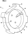
- Figur 4
- eine perspektivische Darstellung des Deckels des Stellglieds gemäß
Figur 3 . - Funktionsäquivalente Elemente und Bereiche tragen in den nachfolgenden Figuren die gleichen Bezugszeichen und sind nicht nochmals im Detail erläutert.
- In
Figur 1 trägt ein elektromagnetisches Stellglied für ein nicht näher bezeichnetes Druckregelventil insgesamt das Bezugszeichen 10. Das Stellglied 10 umfasst ein im Wesentlichen rohrförmiges Gehäuse 12, welches insbesondere aus einem gerollten und verknüpften Blechbauteil hergestellt sein kann. Das Gehäuse 12 verläuft im Wesentlichen rotationssymmetrisch um eine Längsachse 14. Im Gehäuse 12 ist ebenfalls rotationssymmetrisch um die Längsachse 14 verlaufend ein Spulenkörper 16 angeordnet, der eine Magnetspule 18 trägt. Die Magnetspule 18 kann mit einem nicht näher dargestellten Stromanschluss mit Strom versorgt werden. Innerhalb des Spulenkörpers 16 ist ein Polrohr 20 vorgesehen. Das Polrohr 20 weist einen ersten von der Spule 18 umgebenen zylindrischen Abschnitt 21 und einen zweiten am rechten Endbereich derFigur 1 vorgesehenen Abschnitt 23 auf. Der erste Abschnitt 21 weist einen Außendurchmesser D1 auf, während der zweite Abschnitt 23 einen Außendurchmesser D2 aufweist, wobei D2 circa 20% größer ist als D1. Das Polrohr 20 weist an seinem Außenumfang 22 im Bereich des Abschnitts 21 eine insgesamt in etwa V-förmige Aussparung 24 auf. - Die Aussparung 24 ist insoweit als V-Nut ausgebildet und dient zur Verhinderung eines magnetischen Kurzschlusses. Ferner weist das Polrohr 20 eine zylindrische gestufte Innenausnehmung 26 auf. Diese verläuft vom in der
Figur 1 gezeigten rechten Ende des Polrohrs bis zu einem im linken Endbereich vorgesehenen magnetischen Joch 28, welches eine Durchgangsöffnung 30 umfasst. Die Innenausnehmung 26 wird an einem ersten axialen Ende vom Joch 28, in radialer Richtung vom Polrohr 20 und an einem zweiten axialen Ende von einem Deckel 32 begrenzt. Die zylindrische Ausnehmung 26 bildet einen Ankerraum 34 aus, in dem ein Anker 36 gleitverschiebbar gelagert ist. In eine Zentralausnehmung 42 des Ankers 36 ist ein Bolzen 44 eingepresst. Wird der Anker in Richtung des Jochs 28 bewegt, so gelangt der Bolzen 44 zur Anlage an das Stellelement 46 des Stellglieds 10. Das Stellelement 46 ist zweiteilig aufgebaut und umfasst einen durch die Durchgangsöffnung 30 geführten Stößel 48 sowie ein darauf aufgepresstes Trennstück 50, an welches der Bolzen 44 zur Anlage bringbar ist. Das Stellelement 46 kann insbesondere zur Betätigung eines nicht näher dargestellten Ventilelements eines Druckregelventils ausgebildet sein. Auf ein als Vorsprung ausgebildetes, kreiszylindrisches freies Ende 38 des Jochs 28 ist eine kreisringförmige Flussscheibe 40 aufgesetzt. Die Flussscheibe 40 dient zum Leiten eines von der Magnetspule 18 erzeugten magnetischen Flusses. - Wie insbesondere aus
Figur 2 ersichtlich ist, ist der Deckel 32 topfförmig mit einem Deckelmantel 52 und einem Deckelboden 54 ausgebildet. GemäßFigur 1 liegt die Innenumfangsfläche 55 des Deckelmantels 52 an der Außenumfangsfläche 57 des zweiten Abschnitts 23 des Polrohrs 20 an. Zudem liegt der Deckelboden 54 axial am zweiten Abschnitt 23 des Polrohrs 20 an. Dadurch kann eine besonders große Magnetflussübergangsfläche bereitgestellt werden. Zur Ausbildung von Ankeranschlägen 56 weist der Deckelboden 54 eine Anzahl Vorsprünge auf. Ferner ist eine Entlüftungsnut 58 im Deckel 32 vorgesehen, welche sich vom Deckelboden 54 über den Deckelmantel 52 erstreckt. Zur Ausbildung einer Aussparung für einen elektrischen Stecker ist ein Kreissegment von dem ansonsten kreiszylindrischen Deckel 32 ausgespart, so dass ein Abschnitt 60 des Deckelmantels 52 als Gerade ausgebildet ist. - Die Funktionsweise des Stellglieds 10 ist sodann wie folgt: Wird an die Magnetspule 18 ein Strom angelegt, so resultiert daraus ein magnetischer Fluss, wobei ein magnetischer Kreis zwischen Polrohr 20, Flussscheibe 40 und dem Deckel 32 ausgebildet wird. Der Deckel 32 ist folglich zumindest abschnittsweise magnetisch und bildet damit eine Polscheibe 61 aus. Aus dem magnetischen Fluss durch den magnetischen Kreis resultiert eine magnetische Kraft auf den Anker 36, der dadurch entlang der Längsachse 14 je nach Strombeaufschlagung der Spule 18 verschoben wird. Auf Grund der Bewegungskopplung mit dem Stellelement 46 wird dieses ebenfalls in axialer Richtung entlang der Längsachse 14 bewegt.
- Im Unterschied zu der in den
Figuren 1 und2 gezeigten Ausführungsform liegt beiFigur 3 die Innenumfangsfläche 55 des Deckelmantels 52 zwar an der Außenumfangsfläche 57 des zweiten Abschnitts 23 des Polrohrs 20 an.. In axialer Richtung entlang der Längsachse 14 ist der Deckelboden 54 allerdings vom Polrohr 20 um einen Abstand D3 beabstandet. Dadurch wird zwar die Magnetflussübergangsfläche reduziert. Allerdings wird so sichergestellt, dass kein schädlicher Einfluss auf die V-förmige Aussparung 24 des Polrohrs 20 durch eine axiale Befestigungskraft des Deckels 32 ausgeübt wird. Um die axiale Beabstandung sicherzustellen, ist das Polrohr 20 mit der Flussscheibe 40 fest verbunden, beispielsweise vercrimpt oder verpresst. Ferner stützt sich der Deckel 32 am Gehäuse 12 ab, in dem am Außenumfang des Deckelmantels 52 eine Anzahl Vorsprünge 62 (sieheFigur 4 ) vorgesehen sind, die laschenförmig ausgebildet sein können und insbesondere in komplementäre Aussparungen im Gehäuse einführbar sind. Die dem Gehäuse zugewandten Seiten der Vorsprünge 62 dienen folglich als Anschlagflächen zur Anlage an komplementären Anschlagflächen des Gehäuses 12, so dass eine Beabstandung zwischen Deckel 32 und Polrohr 20 sichergestellt ist.
Claims (8)
- Elektromagnetisches Stellglied (10) mit einem Gehäuse (12), mit einem in dem Gehäuse (12) angeordneten und rotationssymmetrisch um eine Längsachse (14) verlaufenden Spulenkörper (16), der eine um die Längsachse (14) verlaufende Spule (18) zur Erzeugung eines Magnetfelds zur Bewegung eines Ankers (36) trägt, wobei innerhalb des Spulenkörpers (16) ein Polrohr (20) vorgesehen ist, wobei das Polrohr (20) einen ersten, von der Spule (18) umgebenen zylindrischen Abschnitt (21) und zweiten Abschnitt (23) aufweist, wobei das Polrohr an seinem Außenumfang (24) im Bereich des ersten Abschnitts (21) eine in etwa V-förmige Aussparung (24) und eine zylindrische Innenausnehmung (26) aufweist, die einen Ankerraum (34) ausbildet, in dem der Anker (36) entlang der Längsachse (14) gleitverschiebbar gelagert ist, wobei das Stellglied weiterhin ein mit dem Anker (36) bewegungsgekoppeltes Stellelement (46), insbesondere zur Betätigung eines Ventilelements eines Druckregelventils, und eine Polscheibe (61) zum Leiten eines magnetischen Flusses und einen Deckel (32) aufweist, wobei der Deckel (32) topfförmig mit einem Deckelmantel (52) und einem Deckelboden ausgebildet ist und der Deckelmantel (52) den zweiten Abschnitt (23) umgibt, wobei der Deckel (32) und die Polscheibe (61) zusammen ein einstückiges Bauteil sind, wobei die den Ankerraum (34) ausbildende Innenausnehmung (26) in radialer Richtung von dem Polrohr (20) und an einem zweiten axialen Ende von dem Deckel (21) begrenzt wird, dadurch gekennzeichnet, dass die den Ankerraum (34) ausbildende Innenausnehmung (26) an einem ersten axialen Ende von einem an dem Polrohr ausgebildeten Joch (28) begrenzt wird und der Deckelmantel (52) mit seiner Innenumfangsfläche (55) an einer Außenumfangsfläche des den Ankerraum (34) begrenzenden Polrohrs (20) anliegt und wobei der Außendurchmesser des zweiten Abschnitts (23) 10% bis 30%, insbesondere 20%, größer ist als der Außendurchmesser des ersten Abschnitts (21).
- Elektromagnetisches Stellglied (10) nach Anspruch 1, dadurch gekennzeichnet, dass der Deckelboden (54) wenigstens einen als Ankeranschlag (56) ausgebildeten Vorsprung aufweist.
- Elektromagnetisches Stellglied (10) nach mindestens einem der Ansprüche 1 oder 2, dadurch gekennzeichnet, dass der Deckelmantel (52) und/oder der Deckelboden (54) wenigstens eine Nut zur Entlüftung des Ankerraums (34) aufweist bzw. aufweisen.
- Elektromagnetisches Stellglied (10) nach mindestens einem der Ansprüche 1 bis 3, dadurch gekennzeichnet, dass der Deckelboden (54) vom Pohlrohr (20) beabstandet ist.
- Elektromagnetisches Stellglied (10) nach mindestens einem der Ansprüche 1 bis 4, dadurch gekennzeichnet, dass auf der vom Deckel (32) abgewandten Seite des Polrohrs (20) eine den Ankerraum (34) begrenzende Flussscheibe (40) vorgesehen ist, die mit dem Polrohr (20) fest verbunden, insbesondere vercrimpt oder verpresst, ist.
- Elektromagnetisches Stellglied (10) nach mindestens einem der der Ansprüche 1 bis 5, dadurch gekennzeichnet, dass der Deckelmantel (52) außenseitig wenigstens einen Vorsprung (62) aufweist, wobei sich der Vorsprung (62) an einem Stellgliedgehäuse (12) abstützt.
- Elektromagnetisches Stellglied (10) nach mindestens einem der vorhergehenden Ansprüche, dadurch gekennzeichnet, dass der Deckel (32) eine Ausnehmung zur Anordnung eines elektrischen Steckers zur Bestromung der Spule (18) umfasst und/oder dass der Deckel (32) pulvermetallurgisch hergestellt, insbesondere gesintert, ist.
- Druckregelventil, umfassend ein Stellglied (10) nach einem der vorhergehenden Ansprüche, wobei ein Ventilelement zum Leiten und Druckregeln eines Arbeitsmediums, wie etwa Öl, mittels des Stellelements (46) betätigbar ist.
Applications Claiming Priority (2)
| Application Number | Priority Date | Filing Date | Title |
|---|---|---|---|
| DE102016220767.9A DE102016220767A1 (de) | 2016-10-21 | 2016-10-21 | Elektromagnetisches Stellglied |
| PCT/EP2017/071566 WO2018072916A1 (de) | 2016-10-21 | 2017-08-28 | Elektromagnetisches stellglied |
Publications (2)
| Publication Number | Publication Date |
|---|---|
| EP3529814A1 EP3529814A1 (de) | 2019-08-28 |
| EP3529814B1 true EP3529814B1 (de) | 2022-10-12 |
Family
ID=59702742
Family Applications (1)
| Application Number | Title | Priority Date | Filing Date |
|---|---|---|---|
| EP17757780.6A Active EP3529814B1 (de) | 2016-10-21 | 2017-08-28 | Elektromagnetisches stellglied |
Country Status (6)
| Country | Link |
|---|---|
| US (1) | US11315715B2 (de) |
| EP (1) | EP3529814B1 (de) |
| KR (1) | KR20190065313A (de) |
| CN (1) | CN109891526B (de) |
| DE (1) | DE102016220767A1 (de) |
| WO (1) | WO2018072916A1 (de) |
Families Citing this family (7)
| Publication number | Priority date | Publication date | Assignee | Title |
|---|---|---|---|---|
| JP2020004848A (ja) * | 2018-06-28 | 2020-01-09 | 日本電産トーソク株式会社 | ソレノイド装置 |
| DE102018217424A1 (de) * | 2018-10-11 | 2020-04-16 | Robert Bosch Gmbh | Elektromagnetische Betätigungseinrichtung |
| DE102018222614A1 (de) * | 2018-12-20 | 2020-06-25 | Robert Bosch Gmbh | Elektromagnetische Betätigungseinrichtung |
| DE102019113409A1 (de) * | 2019-05-21 | 2020-11-26 | ECO Holding 1 GmbH | Aktuator und Ventilblock |
| EP3800650A1 (de) * | 2019-10-01 | 2021-04-07 | HUSCO Automotive Holdings LLC | Doppelt geflanschtes einheitliches polstück und elektromagnetischer aktuator, der das doppelt geflanschte einheitliche polstück umfasst |
| DE102019218092A1 (de) * | 2019-11-22 | 2021-05-27 | Robert Bosch Gmbh | Elektromagnetische Betätigungseinrichtung |
| US11261765B1 (en) | 2020-08-25 | 2022-03-01 | Borgwamer Inc. | Control valve assembly of a variable cam timing phaser |
Citations (3)
| Publication number | Priority date | Publication date | Assignee | Title |
|---|---|---|---|---|
| US4552311A (en) * | 1983-09-23 | 1985-11-12 | Allied Corporation | Low cost unitized fuel injection system |
| US20060011245A1 (en) * | 2004-07-14 | 2006-01-19 | Toyoda Koki Kabushiki Kaisha | Solenoid-operated valve |
| US20140361206A1 (en) * | 2012-01-30 | 2014-12-11 | Borgwarner Inc. | Mono bearing one piece core solenoid |
Family Cites Families (10)
| Publication number | Priority date | Publication date | Assignee | Title |
|---|---|---|---|---|
| FR2889621B1 (fr) | 2005-08-03 | 2011-05-13 | Eaton Corp | Actionneur electromagnetique comportant un tube magnetique et destine a actionner une vanne hydraulique ou pneumatique |
| JP2008196597A (ja) | 2007-02-13 | 2008-08-28 | Denso Corp | リニアソレノイド |
| JP5125441B2 (ja) * | 2007-11-21 | 2013-01-23 | アイシン・エィ・ダブリュ株式会社 | リニアソレノイド装置および電磁弁 |
| DE102008044237B4 (de) | 2008-12-01 | 2026-02-19 | Robert Bosch Gmbh | Druckregelventil |
| KR102008824B1 (ko) * | 2012-06-21 | 2019-08-08 | 보르그워너 인코퍼레이티드 | 침지형 솔레노이드 밸브 |
| JP5733581B2 (ja) * | 2012-11-27 | 2015-06-10 | 株式会社デンソー | 高圧流体用電磁弁装置 |
| DE102012223430A1 (de) | 2012-12-17 | 2014-06-18 | Robert Bosch Gmbh | Elektromagnetisches Stellglied |
| JP6200695B2 (ja) | 2013-05-28 | 2017-09-20 | 川崎重工業株式会社 | 油浸型ソレノイド |
| JP6164167B2 (ja) | 2014-06-25 | 2017-07-19 | 株式会社デンソー | リニアソレノイド |
| DE102014010876B3 (de) | 2014-07-25 | 2015-10-01 | Hilite Germany Gmbh | Aktuator für ein Hydraulikventil eines Nockenwellenschwenkmotorverstellers und Hydraulikventil mit einem Aktuator für einen Nockenwellenschwenkmotorversteller |
-
2016
- 2016-10-21 DE DE102016220767.9A patent/DE102016220767A1/de not_active Withdrawn
-
2017
- 2017-08-28 KR KR1020197011353A patent/KR20190065313A/ko not_active Withdrawn
- 2017-08-28 US US16/342,660 patent/US11315715B2/en active Active
- 2017-08-28 CN CN201780064987.5A patent/CN109891526B/zh active Active
- 2017-08-28 WO PCT/EP2017/071566 patent/WO2018072916A1/de not_active Ceased
- 2017-08-28 EP EP17757780.6A patent/EP3529814B1/de active Active
Patent Citations (3)
| Publication number | Priority date | Publication date | Assignee | Title |
|---|---|---|---|---|
| US4552311A (en) * | 1983-09-23 | 1985-11-12 | Allied Corporation | Low cost unitized fuel injection system |
| US20060011245A1 (en) * | 2004-07-14 | 2006-01-19 | Toyoda Koki Kabushiki Kaisha | Solenoid-operated valve |
| US20140361206A1 (en) * | 2012-01-30 | 2014-12-11 | Borgwarner Inc. | Mono bearing one piece core solenoid |
Also Published As
| Publication number | Publication date |
|---|---|
| KR20190065313A (ko) | 2019-06-11 |
| US11315715B2 (en) | 2022-04-26 |
| DE102016220767A1 (de) | 2018-04-26 |
| WO2018072916A1 (de) | 2018-04-26 |
| CN109891526B (zh) | 2022-07-08 |
| EP3529814A1 (de) | 2019-08-28 |
| CN109891526A (zh) | 2019-06-14 |
| US20190244738A1 (en) | 2019-08-08 |
Similar Documents
| Publication | Publication Date | Title |
|---|---|---|
| EP2932515B1 (de) | Elektromagnetisches stellglied | |
| EP3529814A1 (de) | Elektromagnetisches stellglied | |
| EP3222897B1 (de) | Kippankerventil und verfahren zur herstellung desselben | |
| WO2010086058A1 (de) | Proportionalmagnet für ein hydraulisches wegeventil und verfahren zu dessen herstellung | |
| EP2081805B1 (de) | Magnetventil und zugehörige hydraulische bremsanlage für kraftfahrzeuge | |
| DE19700979A1 (de) | Magnetventil | |
| WO1989010510A2 (en) | Pulsed hydraulic valve | |
| WO2010060690A1 (de) | Elektromagnetische stelleinheit für ein hydraulisches wegeventil und verfahren zu dessen montage | |
| DE102016224288A1 (de) | Elektromagnetisches Stellglied, Flussscheibenkörper für ein elektromagnetisches Stellglied und Verfahren zur Herstellung eines elektromagnetischen Stellgliedes | |
| DE102022207702A1 (de) | Dämpfungsventileinrichtung für einen Schwingungsdämpfer | |
| DE202011001412U1 (de) | Elektromagnetische Stellvorrichtung sowie Nockenwellenverstellvorrichtung | |
| DE102017201470A1 (de) | Elektromagnetventil, insbesondere für schlupfgeregelte Kraftfahrzeugbremsanlagen | |
| DE102018222610A1 (de) | Elektromagnetische Betätigungseinrichtung | |
| DE112021005169T5 (de) | Zylinderspule, Dämpfungskrafteinstellungsmechanismus und Stoßdämpfer mit einstellbarer Dämpfungskraft | |
| DE102006042215B4 (de) | Elektromagnetische Stelleinheit | |
| DE102012209729B4 (de) | Magnetventil | |
| WO2007025631A1 (de) | Hydraulisches wegeventil | |
| WO2016026690A1 (de) | Magnetventil | |
| EP0859380B1 (de) | Elektromechanischer Doppelhubmagnet | |
| DE112023000985T5 (de) | Solenoid, mechanismus zur einstellung einer dämpfungskraft und stossdämpfer mit einstellbarer dämpfungskraft | |
| WO2014019736A1 (de) | Magnetaktor eines schiebenockensystems | |
| DE102008008735B4 (de) | Elektromagnetischer Antrieb | |
| DE10359174A1 (de) | Ventil zum Steuern von Fluiden | |
| DE102020216125A1 (de) | Elektromagnetisches Stellglied | |
| WO2021099007A1 (de) | Elektromagnetische betätigungseinrichtung |
Legal Events
| Date | Code | Title | Description |
|---|---|---|---|
| STAA | Information on the status of an ep patent application or granted ep patent |
Free format text: STATUS: UNKNOWN |
|
| STAA | Information on the status of an ep patent application or granted ep patent |
Free format text: STATUS: THE INTERNATIONAL PUBLICATION HAS BEEN MADE |
|
| PUAI | Public reference made under article 153(3) epc to a published international application that has entered the european phase |
Free format text: ORIGINAL CODE: 0009012 |
|
| STAA | Information on the status of an ep patent application or granted ep patent |
Free format text: STATUS: REQUEST FOR EXAMINATION WAS MADE |
|
| 17P | Request for examination filed |
Effective date: 20190521 |
|
| AK | Designated contracting states |
Kind code of ref document: A1 Designated state(s): AL AT BE BG CH CY CZ DE DK EE ES FI FR GB GR HR HU IE IS IT LI LT LU LV MC MK MT NL NO PL PT RO RS SE SI SK SM TR |
|
| AX | Request for extension of the european patent |
Extension state: BA ME |
|
| DAV | Request for validation of the european patent (deleted) | ||
| DAX | Request for extension of the european patent (deleted) | ||
| RAP1 | Party data changed (applicant data changed or rights of an application transferred) |
Owner name: ROBERT BOSCH GMBH |
|
| TPAC | Observations filed by third parties |
Free format text: ORIGINAL CODE: EPIDOSNTIPA |
|
| STAA | Information on the status of an ep patent application or granted ep patent |
Free format text: STATUS: EXAMINATION IS IN PROGRESS |
|
| 17Q | First examination report despatched |
Effective date: 20210507 |
|
| GRAP | Despatch of communication of intention to grant a patent |
Free format text: ORIGINAL CODE: EPIDOSNIGR1 |
|
| STAA | Information on the status of an ep patent application or granted ep patent |
Free format text: STATUS: GRANT OF PATENT IS INTENDED |
|
| RIC1 | Information provided on ipc code assigned before grant |
Ipc: F16K 31/06 20060101ALI20220609BHEP Ipc: H01F 7/16 20060101ALI20220609BHEP Ipc: H01F 7/08 20060101ALI20220609BHEP Ipc: H01F 7/127 20060101AFI20220609BHEP |
|
| INTG | Intention to grant announced |
Effective date: 20220628 |
|
| GRAS | Grant fee paid |
Free format text: ORIGINAL CODE: EPIDOSNIGR3 |
|
| GRAA | (expected) grant |
Free format text: ORIGINAL CODE: 0009210 |
|
| STAA | Information on the status of an ep patent application or granted ep patent |
Free format text: STATUS: THE PATENT HAS BEEN GRANTED |
|
| AK | Designated contracting states |
Kind code of ref document: B1 Designated state(s): AL AT BE BG CH CY CZ DE DK EE ES FI FR GB GR HR HU IE IS IT LI LT LU LV MC MK MT NL NO PL PT RO RS SE SI SK SM TR |
|
| REG | Reference to a national code |
Ref country code: GB Ref legal event code: FG4D Free format text: NOT ENGLISH |
|
| REG | Reference to a national code |
Ref country code: CH Ref legal event code: EP |
|
| REG | Reference to a national code |
Ref country code: DE Ref legal event code: R096 Ref document number: 502017013955 Country of ref document: DE |
|
| REG | Reference to a national code |
Ref country code: IE Ref legal event code: FG4D Free format text: LANGUAGE OF EP DOCUMENT: GERMAN |
|
| REG | Reference to a national code |
Ref country code: AT Ref legal event code: REF Ref document number: 1524673 Country of ref document: AT Kind code of ref document: T Effective date: 20221115 |
|
| REG | Reference to a national code |
Ref country code: LT Ref legal event code: MG9D |
|
| REG | Reference to a national code |
Ref country code: NL Ref legal event code: MP Effective date: 20221012 |
|
| PG25 | Lapsed in a contracting state [announced via postgrant information from national office to epo] |
Ref country code: NL Free format text: LAPSE BECAUSE OF FAILURE TO SUBMIT A TRANSLATION OF THE DESCRIPTION OR TO PAY THE FEE WITHIN THE PRESCRIBED TIME-LIMIT Effective date: 20221012 |
|
| PG25 | Lapsed in a contracting state [announced via postgrant information from national office to epo] |
Ref country code: SE Free format text: LAPSE BECAUSE OF FAILURE TO SUBMIT A TRANSLATION OF THE DESCRIPTION OR TO PAY THE FEE WITHIN THE PRESCRIBED TIME-LIMIT Effective date: 20221012 Ref country code: PT Free format text: LAPSE BECAUSE OF FAILURE TO SUBMIT A TRANSLATION OF THE DESCRIPTION OR TO PAY THE FEE WITHIN THE PRESCRIBED TIME-LIMIT Effective date: 20230213 Ref country code: NO Free format text: LAPSE BECAUSE OF FAILURE TO SUBMIT A TRANSLATION OF THE DESCRIPTION OR TO PAY THE FEE WITHIN THE PRESCRIBED TIME-LIMIT Effective date: 20230112 Ref country code: LT Free format text: LAPSE BECAUSE OF FAILURE TO SUBMIT A TRANSLATION OF THE DESCRIPTION OR TO PAY THE FEE WITHIN THE PRESCRIBED TIME-LIMIT Effective date: 20221012 Ref country code: FI Free format text: LAPSE BECAUSE OF FAILURE TO SUBMIT A TRANSLATION OF THE DESCRIPTION OR TO PAY THE FEE WITHIN THE PRESCRIBED TIME-LIMIT Effective date: 20221012 Ref country code: ES Free format text: LAPSE BECAUSE OF FAILURE TO SUBMIT A TRANSLATION OF THE DESCRIPTION OR TO PAY THE FEE WITHIN THE PRESCRIBED TIME-LIMIT Effective date: 20221012 |
|
| PG25 | Lapsed in a contracting state [announced via postgrant information from national office to epo] |
Ref country code: RS Free format text: LAPSE BECAUSE OF FAILURE TO SUBMIT A TRANSLATION OF THE DESCRIPTION OR TO PAY THE FEE WITHIN THE PRESCRIBED TIME-LIMIT Effective date: 20221012 Ref country code: PL Free format text: LAPSE BECAUSE OF FAILURE TO SUBMIT A TRANSLATION OF THE DESCRIPTION OR TO PAY THE FEE WITHIN THE PRESCRIBED TIME-LIMIT Effective date: 20221012 Ref country code: LV Free format text: LAPSE BECAUSE OF FAILURE TO SUBMIT A TRANSLATION OF THE DESCRIPTION OR TO PAY THE FEE WITHIN THE PRESCRIBED TIME-LIMIT Effective date: 20221012 Ref country code: IS Free format text: LAPSE BECAUSE OF FAILURE TO SUBMIT A TRANSLATION OF THE DESCRIPTION OR TO PAY THE FEE WITHIN THE PRESCRIBED TIME-LIMIT Effective date: 20230212 Ref country code: HR Free format text: LAPSE BECAUSE OF FAILURE TO SUBMIT A TRANSLATION OF THE DESCRIPTION OR TO PAY THE FEE WITHIN THE PRESCRIBED TIME-LIMIT Effective date: 20221012 Ref country code: GR Free format text: LAPSE BECAUSE OF FAILURE TO SUBMIT A TRANSLATION OF THE DESCRIPTION OR TO PAY THE FEE WITHIN THE PRESCRIBED TIME-LIMIT Effective date: 20230113 |
|
| REG | Reference to a national code |
Ref country code: DE Ref legal event code: R097 Ref document number: 502017013955 Country of ref document: DE |
|
| PG25 | Lapsed in a contracting state [announced via postgrant information from national office to epo] |
Ref country code: SM Free format text: LAPSE BECAUSE OF FAILURE TO SUBMIT A TRANSLATION OF THE DESCRIPTION OR TO PAY THE FEE WITHIN THE PRESCRIBED TIME-LIMIT Effective date: 20221012 Ref country code: RO Free format text: LAPSE BECAUSE OF FAILURE TO SUBMIT A TRANSLATION OF THE DESCRIPTION OR TO PAY THE FEE WITHIN THE PRESCRIBED TIME-LIMIT Effective date: 20221012 Ref country code: EE Free format text: LAPSE BECAUSE OF FAILURE TO SUBMIT A TRANSLATION OF THE DESCRIPTION OR TO PAY THE FEE WITHIN THE PRESCRIBED TIME-LIMIT Effective date: 20221012 Ref country code: DK Free format text: LAPSE BECAUSE OF FAILURE TO SUBMIT A TRANSLATION OF THE DESCRIPTION OR TO PAY THE FEE WITHIN THE PRESCRIBED TIME-LIMIT Effective date: 20221012 Ref country code: CZ Free format text: LAPSE BECAUSE OF FAILURE TO SUBMIT A TRANSLATION OF THE DESCRIPTION OR TO PAY THE FEE WITHIN THE PRESCRIBED TIME-LIMIT Effective date: 20221012 |
|
| PLBE | No opposition filed within time limit |
Free format text: ORIGINAL CODE: 0009261 |
|
| STAA | Information on the status of an ep patent application or granted ep patent |
Free format text: STATUS: NO OPPOSITION FILED WITHIN TIME LIMIT |
|
| PG25 | Lapsed in a contracting state [announced via postgrant information from national office to epo] |
Ref country code: SK Free format text: LAPSE BECAUSE OF FAILURE TO SUBMIT A TRANSLATION OF THE DESCRIPTION OR TO PAY THE FEE WITHIN THE PRESCRIBED TIME-LIMIT Effective date: 20221012 Ref country code: AL Free format text: LAPSE BECAUSE OF FAILURE TO SUBMIT A TRANSLATION OF THE DESCRIPTION OR TO PAY THE FEE WITHIN THE PRESCRIBED TIME-LIMIT Effective date: 20221012 |
|
| 26N | No opposition filed |
Effective date: 20230713 |
|
| PG25 | Lapsed in a contracting state [announced via postgrant information from national office to epo] |
Ref country code: SI Free format text: LAPSE BECAUSE OF FAILURE TO SUBMIT A TRANSLATION OF THE DESCRIPTION OR TO PAY THE FEE WITHIN THE PRESCRIBED TIME-LIMIT Effective date: 20221012 |
|
| PG25 | Lapsed in a contracting state [announced via postgrant information from national office to epo] |
Ref country code: MC Free format text: LAPSE BECAUSE OF FAILURE TO SUBMIT A TRANSLATION OF THE DESCRIPTION OR TO PAY THE FEE WITHIN THE PRESCRIBED TIME-LIMIT Effective date: 20221012 |
|
| REG | Reference to a national code |
Ref country code: CH Ref legal event code: PL |
|
| PG25 | Lapsed in a contracting state [announced via postgrant information from national office to epo] |
Ref country code: MC Free format text: LAPSE BECAUSE OF FAILURE TO SUBMIT A TRANSLATION OF THE DESCRIPTION OR TO PAY THE FEE WITHIN THE PRESCRIBED TIME-LIMIT Effective date: 20221012 |
|
| PG25 | Lapsed in a contracting state [announced via postgrant information from national office to epo] |
Ref country code: LU Free format text: LAPSE BECAUSE OF NON-PAYMENT OF DUE FEES Effective date: 20230828 |
|
| GBPC | Gb: european patent ceased through non-payment of renewal fee |
Effective date: 20230828 |
|
| PG25 | Lapsed in a contracting state [announced via postgrant information from national office to epo] |
Ref country code: LU Free format text: LAPSE BECAUSE OF NON-PAYMENT OF DUE FEES Effective date: 20230828 Ref country code: CH Free format text: LAPSE BECAUSE OF NON-PAYMENT OF DUE FEES Effective date: 20230831 |
|
| REG | Reference to a national code |
Ref country code: BE Ref legal event code: MM Effective date: 20230831 |
|
| REG | Reference to a national code |
Ref country code: IE Ref legal event code: MM4A |
|
| PG25 | Lapsed in a contracting state [announced via postgrant information from national office to epo] |
Ref country code: IT Free format text: LAPSE BECAUSE OF FAILURE TO SUBMIT A TRANSLATION OF THE DESCRIPTION OR TO PAY THE FEE WITHIN THE PRESCRIBED TIME-LIMIT Effective date: 20221012 |
|
| PG25 | Lapsed in a contracting state [announced via postgrant information from national office to epo] |
Ref country code: IE Free format text: LAPSE BECAUSE OF NON-PAYMENT OF DUE FEES Effective date: 20230828 |
|
| PG25 | Lapsed in a contracting state [announced via postgrant information from national office to epo] |
Ref country code: GB Free format text: LAPSE BECAUSE OF NON-PAYMENT OF DUE FEES Effective date: 20230828 |
|
| PG25 | Lapsed in a contracting state [announced via postgrant information from national office to epo] |
Ref country code: IE Free format text: LAPSE BECAUSE OF NON-PAYMENT OF DUE FEES Effective date: 20230828 Ref country code: GB Free format text: LAPSE BECAUSE OF NON-PAYMENT OF DUE FEES Effective date: 20230828 |
|
| PG25 | Lapsed in a contracting state [announced via postgrant information from national office to epo] |
Ref country code: BE Free format text: LAPSE BECAUSE OF NON-PAYMENT OF DUE FEES Effective date: 20230831 |
|
| REG | Reference to a national code |
Ref country code: AT Ref legal event code: MM01 Ref document number: 1524673 Country of ref document: AT Kind code of ref document: T Effective date: 20230828 |
|
| PG25 | Lapsed in a contracting state [announced via postgrant information from national office to epo] |
Ref country code: AT Free format text: LAPSE BECAUSE OF NON-PAYMENT OF DUE FEES Effective date: 20230828 |
|
| PG25 | Lapsed in a contracting state [announced via postgrant information from national office to epo] |
Ref country code: AT Free format text: LAPSE BECAUSE OF NON-PAYMENT OF DUE FEES Effective date: 20230828 |
|
| PG25 | Lapsed in a contracting state [announced via postgrant information from national office to epo] |
Ref country code: BG Free format text: LAPSE BECAUSE OF FAILURE TO SUBMIT A TRANSLATION OF THE DESCRIPTION OR TO PAY THE FEE WITHIN THE PRESCRIBED TIME-LIMIT Effective date: 20221012 |
|
| PG25 | Lapsed in a contracting state [announced via postgrant information from national office to epo] |
Ref country code: BG Free format text: LAPSE BECAUSE OF FAILURE TO SUBMIT A TRANSLATION OF THE DESCRIPTION OR TO PAY THE FEE WITHIN THE PRESCRIBED TIME-LIMIT Effective date: 20221012 |
|
| PG25 | Lapsed in a contracting state [announced via postgrant information from national office to epo] |
Ref country code: CY Free format text: LAPSE BECAUSE OF FAILURE TO SUBMIT A TRANSLATION OF THE DESCRIPTION OR TO PAY THE FEE WITHIN THE PRESCRIBED TIME-LIMIT; INVALID AB INITIO Effective date: 20170828 |
|
| PG25 | Lapsed in a contracting state [announced via postgrant information from national office to epo] |
Ref country code: HU Free format text: LAPSE BECAUSE OF FAILURE TO SUBMIT A TRANSLATION OF THE DESCRIPTION OR TO PAY THE FEE WITHIN THE PRESCRIBED TIME-LIMIT; INVALID AB INITIO Effective date: 20170828 |
|
| PGFP | Annual fee paid to national office [announced via postgrant information from national office to epo] |
Ref country code: FR Payment date: 20250821 Year of fee payment: 9 |
|
| PG25 | Lapsed in a contracting state [announced via postgrant information from national office to epo] |
Ref country code: TR Free format text: LAPSE BECAUSE OF FAILURE TO SUBMIT A TRANSLATION OF THE DESCRIPTION OR TO PAY THE FEE WITHIN THE PRESCRIBED TIME-LIMIT Effective date: 20221012 |
|
| PGFP | Annual fee paid to national office [announced via postgrant information from national office to epo] |
Ref country code: DE Payment date: 20251021 Year of fee payment: 9 |