EP3529634B1 - 3d-lidar-sensor - Google Patents
3d-lidar-sensor Download PDFInfo
- Publication number
- EP3529634B1 EP3529634B1 EP17797239.5A EP17797239A EP3529634B1 EP 3529634 B1 EP3529634 B1 EP 3529634B1 EP 17797239 A EP17797239 A EP 17797239A EP 3529634 B1 EP3529634 B1 EP 3529634B1
- Authority
- EP
- European Patent Office
- Prior art keywords
- laser beam
- lidar sensor
- light sensors
- scanning system
- sensors
- Prior art date
- Legal status (The legal status is an assumption and is not a legal conclusion. Google has not performed a legal analysis and makes no representation as to the accuracy of the status listed.)
- Active
Links
Images


Classifications
-
- G—PHYSICS
- G01—MEASURING; TESTING
- G01S—RADIO DIRECTION-FINDING; RADIO NAVIGATION; DETERMINING DISTANCE OR VELOCITY BY USE OF RADIO WAVES; LOCATING OR PRESENCE-DETECTING BY USE OF THE REFLECTION OR RERADIATION OF RADIO WAVES; ANALOGOUS ARRANGEMENTS USING OTHER WAVES
- G01S17/00—Systems using the reflection or reradiation of electromagnetic waves other than radio waves, e.g. lidar systems
- G01S17/02—Systems using the reflection of electromagnetic waves other than radio waves
- G01S17/06—Systems determining position data of a target
- G01S17/42—Simultaneous measurement of distance and other co-ordinates
-
- G—PHYSICS
- G01—MEASURING; TESTING
- G01S—RADIO DIRECTION-FINDING; RADIO NAVIGATION; DETERMINING DISTANCE OR VELOCITY BY USE OF RADIO WAVES; LOCATING OR PRESENCE-DETECTING BY USE OF THE REFLECTION OR RERADIATION OF RADIO WAVES; ANALOGOUS ARRANGEMENTS USING OTHER WAVES
- G01S7/00—Details of systems according to groups G01S13/00, G01S15/00, G01S17/00
- G01S7/48—Details of systems according to groups G01S13/00, G01S15/00, G01S17/00 of systems according to group G01S17/00
- G01S7/481—Constructional features, e.g. arrangements of optical elements
- G01S7/4811—Constructional features, e.g. arrangements of optical elements common to transmitter and receiver
- G01S7/4813—Housing arrangements
-
- G—PHYSICS
- G01—MEASURING; TESTING
- G01S—RADIO DIRECTION-FINDING; RADIO NAVIGATION; DETERMINING DISTANCE OR VELOCITY BY USE OF RADIO WAVES; LOCATING OR PRESENCE-DETECTING BY USE OF THE REFLECTION OR RERADIATION OF RADIO WAVES; ANALOGOUS ARRANGEMENTS USING OTHER WAVES
- G01S7/00—Details of systems according to groups G01S13/00, G01S15/00, G01S17/00
- G01S7/48—Details of systems according to groups G01S13/00, G01S15/00, G01S17/00 of systems according to group G01S17/00
- G01S7/497—Means for monitoring or calibrating
-
- G—PHYSICS
- G01—MEASURING; TESTING
- G01S—RADIO DIRECTION-FINDING; RADIO NAVIGATION; DETERMINING DISTANCE OR VELOCITY BY USE OF RADIO WAVES; LOCATING OR PRESENCE-DETECTING BY USE OF THE REFLECTION OR RERADIATION OF RADIO WAVES; ANALOGOUS ARRANGEMENTS USING OTHER WAVES
- G01S17/00—Systems using the reflection or reradiation of electromagnetic waves other than radio waves, e.g. lidar systems
- G01S17/88—Lidar systems specially adapted for specific applications
- G01S17/93—Lidar systems specially adapted for specific applications for anti-collision purposes
- G01S17/931—Lidar systems specially adapted for specific applications for anti-collision purposes of land vehicles
-
- G—PHYSICS
- G01—MEASURING; TESTING
- G01S—RADIO DIRECTION-FINDING; RADIO NAVIGATION; DETERMINING DISTANCE OR VELOCITY BY USE OF RADIO WAVES; LOCATING OR PRESENCE-DETECTING BY USE OF THE REFLECTION OR RERADIATION OF RADIO WAVES; ANALOGOUS ARRANGEMENTS USING OTHER WAVES
- G01S7/00—Details of systems according to groups G01S13/00, G01S15/00, G01S17/00
- G01S7/48—Details of systems according to groups G01S13/00, G01S15/00, G01S17/00 of systems according to group G01S17/00
- G01S7/497—Means for monitoring or calibrating
- G01S2007/4975—Means for monitoring or calibrating of sensor obstruction by, e.g. dirt- or ice-coating, e.g. by reflection measurement on front-screen
Definitions
- the invention relates to a 3D LIDAR sensor, in particular for motor vehicles, with a laser beam source, an optical receiver and a scanning system for deflecting a laser beam generated by the laser beam source in two mutually perpendicular scanning directions.
- Such a 3D LIDAR sensor is known.
- laser beams with a wavelength between 850 and 1500 nm of suitable intensity are used to avoid endangering people from the laser beams.
- a micromirror actuator or a MEMS (micro-electro-mechanical system), for example, is used to deflect the laser beam in order to direct the laser beam in the desired direction. If a time-of-flight measurement of the emitted laser beam, reflected by an object and received by the optical receiver, is also carried out, a three-dimensional image of the surroundings can be recorded and interpreted using appropriate evaluation devices and/or driver assistance systems.
- Such a 3D LIDAR sensor is usually arranged in a housing that is equipped with an exit opening in the form of a disk or lens for the laser beam.
- a LIDAR sensor is known in which an additional scanning device is used to detect deviations from normal operation.
- the additional scanning device is set up to evaluate data from a sensor to determine whether it lies within or outside a predefined error range.
- a LIDAR sensor is known in which an additional LED and an additional receiving diode for the light of the LED can be used to detect contamination of the sensor.
- the object of the invention is to provide a 3D LIDAR sensor with improved functionality and reliability, which is particularly suitable for motor vehicles, as set out in claim 1.
- a further detection device for deviations from normal operation is provided in or on the 3D LIDAR sensor.
- the detection device can be designed in any way, but preferably as described below.
- This detection device can also be referred to as an "intelligent plane" which is arranged in or on the sensor, for example in the transmission and/or reception path of the sensor's laser beam.
- This plane can be arranged, for example, inside a housing of the sensor or at the outlet opening.
- the direction of the laser beam's emission is detected at reference points.
- Additional light sensors are arranged at an intermediate level and/or at the exit opening, which do not need to be illuminated during normal operation of the laser and the scanning system. If this happens, however, it can be automatically detected that the laser or the scanning system is misaligned and a corresponding error message can be issued or a self-calibration of the entire system is carried out. In the same way, it can be provided that the light sensors have to be illuminated during normal operation. If this does not happen, a misalignment can be detected automatically. closed. This can be implemented in the form of laser light detectors that are arranged at the edge of the exit opening or in the area of a so-called intermediate plane.
- This direction can be changed by mechanical/thermal influences, e.g. by thermal expansion of the housing of the 3D LIDAR sensor or the distance of the micromirrors to a microlens array.
- mechanical misalignment of the entire sensor e.g. due to a collision of the motor vehicle.
- the laser itself can also exhibit thermal drift during continuous operation, e.g. a laser delay after a trigger pulse.
- the irradiation of external light or the light of other LIDAR sensors in motor vehicles can be detected and suppressed, for example based on other frequencies, pulse durations or the like.
- Bandpass filters and/or corresponding coatings, for example on the exit opening, which are only permeable to light of a certain wavelength, are used for this purpose.
- data transmission between the sensors of different motor vehicles would also be possible here, for example to improve traffic flow.
- an unusual deviation is detected in the backscattered laser light received by the optical receiver or an additional scattered light sensor, for example a back reflection by fog, spray or a retroreflection by solar radiation, this can be detected by an additional detection device and taken into account in the evaluation.
- Ambient light detection can also be provided, e.g. in the form of a brightness sensor, in order to take into account the changed lighting conditions when entering a tunnel or an underground car park, for example.
- a close-meshed grid of photosensitive resistance threads be arranged either at the exit opening or at an intermediate level in order to check whether the laser beam actually covers all the desired observation areas during continuous operation. This makes it possible to determine whether there are any gaps in the detection area.
- a piezoelectric effect to change the thickness of the disc or lens of the exit opening or a disc in an intermediate plane in order to change the transmission behavior.
- This can also be a Fabry-Perot filter effect. This means that only the desired wavelength can be received even if the laser wavelength drifts, and other wavelengths are suppressed. This can also be done over a very narrow band.
- a reverse piezoelectric effect at the exit opening to detect and compensate for influences from gusts of wind, other sound signals or the like on the transmission or reception directions of the laser beams, depending on the speed of the vehicle.
- an ultrasonic sensor can be provided in, on or in addition to the 3D LIDAR sensor to enable further monitoring of the vehicle's surroundings.
- a temperature sensor can also be provided which, for example, measures the ambient and/or road surface temperature in order to take this into account when evaluating the signal.
- a detector could also be provided for radioactive radiation, which could influence the measurement results.
- the disc or lens at the exit opening is designed to be dirt-repellent, for example with a lotus effect coating.
- the 3D LIDAR sensor can also be combined with a fog sensor to detect fogging caused by rainwater, haze or mist, for example, and to take this into account when evaluating the measurement results.
- the disc or lens at the exit opening be particularly impact and scratch resistant, for example to withstand stone chips. This can be achieved using a diamond coating, among other things.
- damage detection can be carried out, for example, by means of integrated resistance or strain gauges to detect damage to the disc or lens of the exit opening.
- an expanding and/or focusing optic e.g. in the form of a microlens array, can also be arranged for the emitted and/or backscattered laser beams in order to increase the angle of view.
- a chemical detector can also be provided which, for example, detects the use of road salt, smog or other environmental influences in order to take these into account when evaluating the measurement results.
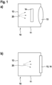
- the in Fig. 1 The 3D LIDAR sensor 10 shown on the left has a laser beam source 11 which, as indicated by the various arrows, is designed to emit laser beams 20 in at least two spatial directions that are perpendicular to one another. Together with an optical receiver (not shown here to simplify the illustration), the surroundings of a motor vehicle in particular can thus be monitored.
- the 3D LIDAR sensor comprises a housing 12 and is arranged, for example, on or in a body of a motor vehicle. It goes without saying that it is equipped with an electrical power supply and with data transmission means in order to forward measurement signals to a control device of the motor vehicle for further processing. Furthermore, a disk or lens 13 is arranged on the housing in order to allow the laser beams 20 to exit and, if necessary, to enter again.
- a further detection device 14, arranged here between the laser beam source 11 and the disk or lens 13, is provided in order to increase the functionality of the 3D LIDAR sensor 10. As in Fig. 1 As shown on the right, this detection device 14 can also be integrated into the disk or lens 13.
- a temperature sensor 28 can also be provided which detects the ambient temperature or which is designed to detect a mirage effect, since mirages on hot road surfaces in particular could influence the measurement results or their evaluation.
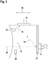
- a laser beam source 11 is shown with a mirror 16, which, as indicated by the double arrow, can be pivoted in two spatial directions perpendicular to one another in order to illuminate the surroundings of the motor vehicle.
- the laser beams 20 exit the 3D LIDAR sensor 10 through a disk or lens 13. Additional light sensors 15 are arranged at the corners of the disk or lens 13. If the direction of the laser beams 20 is misaligned due to thermal and/or mechanical and/or temporal changes, the laser light is no longer directed directly through the disk or lens 13 but hits a surrounding edge of the housing 12. This is detected by the light sensors 15 and a self-adjustment can be carried out or an error message can be issued.
- the light sensors 15 can be arranged not only at the corners but also around the entire edge of the pane or lens 13.
- a scattered light sensor 25 is also shown. This can, for example, detect that a laser beam 20 is directly reflected by dirt 17 on the pane or lens 13. The laser beam 20 is then no longer used to detect the surroundings and an error message can be issued.
- FIG 3 a cross-section of a disk or lens 13 of a 3D LIDAR sensor is shown.
- light sensors 15 are not only arranged around the disk or lens 13 but also on the edge of the disk or lens 13. If a laser beam 20 hits a contamination 17, for example, it can be reflected within the disk or lens 13 as scattered light 18. The same applies to damage 19 to the disk or lens 13. This can be determined by the light sensors 15 on the edge of the disk or lens 13. Contamination 17 can also be formed and detected by water drops, dew, fogging or the like. Temperature influences, chemical or radioactive influences from the environment can also be recorded and taken into account in the evaluation.
- the 3D LIDAR sensor 10 can be equipped with appropriate sensors or networked.
- a drop of rain or water or fog or dew, which affects the transmission behavior of incoming and outgoing laser beams, can also be considered as contamination 17.
- a photoresistor 27 can also be provided to detect the ambient light so that the 3D LIDAR sensor 10 automatically can detect that you are entering a tunnel, a parking garage or the like in order to take the changed lighting conditions into account.
- a scratch-resistant and/or lotus coating can also be provided.
- an environmental influence such as road salt contamination can be detected additionally or alternatively with a chemically sensitive coating.
- the thickness of the disk or lens 13, as indicated by the double arrow 28, can be adjusted, for example by means of a piezoelectric effect, in order to obtain a desired transmission behavior for laser beams 20, for example depending on temperature and/or air pressure.
- the influence of sound waves, the wind and the like on the lens or disk 13 can be detected by piezoelectric detection and taken into account in the evaluation.
- scintillating atoms or molecules can also be incorporated into the disk or lens 13, as indicated by box 28. These would be excited by radioactive radiation and emit light, which would be detected by corresponding detectors, for example at the edge of the disk or lens 13. In this way, the influence of radioactive radiation can be determined and taken into account in the evaluation.
- a scan path 21 of a laser beam 20 over the disk or lens 13 can be shifted by any influence. This is then determined by the light sensors 15, for example, and then adjusted accordingly.
- the pane or lens 13 can be equipped with a lotus coating, a scratch-resistant coating and/or a coating for allowing only certain wavelengths to pass through. The same applies to a component arranged inside the 3D LIDAR sensor 10.
- a bandpass filter and/or a photoresistor can also be provided as an additional coating. For example, the entry of laser beams from other motor vehicles must be prevented in order to avoid interference or other disturbances.
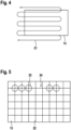
- a disk or lens 13 is depicted on or in which photosensitive resistance wires 22 are arranged, for example in a network. If a laser beam 20 hits such a wire 22, an electrical pulse is triggered, illustrated by the circle 23. If, for example, a mechanical error has occurred in the mirror 16 and an area 24 is not covered by the laser beam, the electrical signal remains missing and an error message can be output.
- a disk or lens 13 is shown in cross-section.
- a bandpass filter is preferably arranged around its edge in order to filter out light rays 26 of an undesirable wavelength, for example from sensors of other motor vehicles, so that the measurement results are not distorted. Only the laser beams 20 of the own 3D LIDAR sensor 10 are to be recorded.
- Fig.7 Three different designs of the so-called intelligent intermediate level are shown. On the left, this is transparent and allows the reflected laser beams to pass through unfiltered. In the middle, it is completely darkened and only allows light of a certain wavelength to pass through, for example, and on the right, only a part is darkened in order to specifically block out unwanted light radiation, for example. This can be done with micro-arrays and/or photosensitive, controllable coatings.
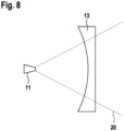
- a disk or lens 13 with expanding properties The laser beams generated by a laser beam source 11 are expanded by the disk or lens 13 in order to be able to cover a larger surrounding area. In principle, a focusing design is also possible.
Landscapes
- Engineering & Computer Science (AREA)
- Physics & Mathematics (AREA)
- Computer Networks & Wireless Communication (AREA)
- General Physics & Mathematics (AREA)
- Radar, Positioning & Navigation (AREA)
- Remote Sensing (AREA)
- Electromagnetism (AREA)
- Optical Radar Systems And Details Thereof (AREA)
- Measurement Of Optical Distance (AREA)
- Mechanical Optical Scanning Systems (AREA)
Applications Claiming Priority (2)
| Application Number | Priority Date | Filing Date | Title |
|---|---|---|---|
| DE102016220504.8A DE102016220504A1 (de) | 2016-10-19 | 2016-10-19 | 3D-LIDAR-Sensor |
| PCT/EP2017/074980 WO2018072986A1 (de) | 2016-10-19 | 2017-10-02 | 3d-lidar-sensor |
Publications (2)
| Publication Number | Publication Date |
|---|---|
| EP3529634A1 EP3529634A1 (de) | 2019-08-28 |
| EP3529634B1 true EP3529634B1 (de) | 2024-12-11 |
Family
ID=60302060
Family Applications (1)
| Application Number | Title | Priority Date | Filing Date |
|---|---|---|---|
| EP17797239.5A Active EP3529634B1 (de) | 2016-10-19 | 2017-10-02 | 3d-lidar-sensor |
Country Status (6)
Families Citing this family (12)
| Publication number | Priority date | Publication date | Assignee | Title |
|---|---|---|---|---|
| US11556000B1 (en) | 2019-08-22 | 2023-01-17 | Red Creamery Llc | Distally-actuated scanning mirror |
| US12399278B1 (en) | 2016-02-15 | 2025-08-26 | Red Creamery Llc | Hybrid LIDAR with optically enhanced scanned laser |
| US12399279B1 (en) | 2016-02-15 | 2025-08-26 | Red Creamery Llc | Enhanced hybrid LIDAR with high-speed scanning |
| US12123950B2 (en) | 2016-02-15 | 2024-10-22 | Red Creamery, LLC | Hybrid LADAR with co-planar scanning and imaging field-of-view |
| DE102017206923B4 (de) * | 2017-04-25 | 2020-12-31 | Robert Bosch Gmbh | Steuerung einer gerichteten Lichtquelle |
| EP3637128A1 (de) * | 2018-10-10 | 2020-04-15 | Covestro Deutschland AG | Umfeldsensor mit beweglicher umlenkeinrichtung für kraftfahrzeuge |
| DE102020112311B3 (de) * | 2020-05-06 | 2021-05-20 | Audi Aktiengesellschaft | Kraftfahrzeug mit einem optischen Umgebungssensor und Verfahren zum Betrieb eines Kraftfahrzeugs |
| JP7603431B2 (ja) * | 2020-12-08 | 2024-12-20 | 京セラ株式会社 | 電磁波検出装置及び電磁波検出方法 |
| CN112965070A (zh) * | 2021-02-01 | 2021-06-15 | 江西欧迈斯微电子有限公司 | 扫地机和扫地机表面异物的检测方法 |
| CN113391294B (zh) * | 2021-06-18 | 2021-12-31 | 特斯联科技集团有限公司 | 多线激光雷达约束调节系统及检测方法 |
| US20240176000A1 (en) * | 2022-11-30 | 2024-05-30 | Continental Autonomous Mobility US, LLC | Optical element damage detection including strain gauge |
| DE102023205156A1 (de) * | 2023-06-02 | 2024-12-05 | Zf Friedrichshafen Ag | Vorrichtung und Verfahren zur Bestimmung von Abtastlücken in einem Abtastbereich eines Lidarsensors |
Family Cites Families (28)
| Publication number | Priority date | Publication date | Assignee | Title |
|---|---|---|---|---|
| US3739174A (en) * | 1971-01-04 | 1973-06-12 | Bell Telephone Labor Inc | Integrating electromagnetic beam position sensor |
| JPH0659038A (ja) | 1992-08-07 | 1994-03-04 | Nissan Motor Co Ltd | 車両用レーザレーダ |
| DE4340756C5 (de) * | 1992-12-08 | 2006-08-10 | Sick Ag | Laserabstandsermittlungsvorrichtung |
| US5455669A (en) * | 1992-12-08 | 1995-10-03 | Erwin Sick Gmbh Optik-Elektronik | Laser range finding apparatus |
| US5585605A (en) * | 1993-11-05 | 1996-12-17 | Microfield Graphics, Inc. | Optical-scanning system employing laser and laser safety control |
| CN1057606C (zh) * | 1993-12-29 | 2000-10-18 | 现代电子产业株式会社 | 使用清除装置的光学测距装置及其方法 |
| JP3351184B2 (ja) * | 1995-07-14 | 2002-11-25 | オムロン株式会社 | 軸数検出装置及び車幅検出装置 |
| JP3244438B2 (ja) * | 1996-11-07 | 2002-01-07 | オムロン株式会社 | 物体情報検知装置 |
| JPH11142520A (ja) * | 1997-11-06 | 1999-05-28 | Omron Corp | 測距装置の軸調整方法及び軸ずれ検出方法並びに測距装置 |
| JP2002031685A (ja) * | 2000-07-17 | 2002-01-31 | Denso Corp | 反射測定装置 |
| JP2002236176A (ja) * | 2001-02-07 | 2002-08-23 | Honda Motor Co Ltd | 車両用物体検知装置の軸調整装置 |
| JP3915742B2 (ja) * | 2003-06-20 | 2007-05-16 | 株式会社デンソー | 車両用物体認識装置 |
| JP4158725B2 (ja) * | 2004-03-09 | 2008-10-01 | 株式会社デンソー | 距離検出装置 |
| JP4305231B2 (ja) * | 2004-03-16 | 2009-07-29 | 株式会社デンソー | 距離検出装置 |
| JP4341435B2 (ja) * | 2004-03-18 | 2009-10-07 | 株式会社デンソー | 距離検出装置 |
| DE102004055680A1 (de) * | 2004-11-18 | 2006-05-24 | Delphi Technologies, Inc., Troy | Sensor zur Überwachung des Nahbereichs an einem Kraftfahrzeug |
| JP2008058173A (ja) * | 2006-08-31 | 2008-03-13 | Olympus Imaging Corp | 車載用のレーダ装置に用いるスキャナ |
| JP2009204903A (ja) * | 2008-02-28 | 2009-09-10 | Seiko Epson Corp | 光走査装置及びその異常検出方法 |
| DE102009027797A1 (de) * | 2008-11-19 | 2010-05-20 | Robert Bosch Gmbh | Optische Einrichtung und Verfahren zu deren Überprüfung |
| EP3901653A3 (en) * | 2010-05-17 | 2022-03-02 | Velodyne Lidar USA, Inc. | High definition lidar system |
| EP2551635A1 (de) * | 2011-07-26 | 2013-01-30 | Hexagon Technology Center GmbH | Optisches Messsystem mit Filtereinheit zur Extraktion elektromagnetischer Strahlung |
| US9195914B2 (en) * | 2012-09-05 | 2015-11-24 | Google Inc. | Construction zone sign detection |
| JP6321448B2 (ja) * | 2013-06-03 | 2018-05-09 | 株式会社デンソー | レーダ装置、及びプログラム |
| JP5944876B2 (ja) * | 2013-10-18 | 2016-07-05 | 増田 麻言 | レーザ光を用いた距離測定装置 |
| JP6634667B2 (ja) * | 2014-07-18 | 2020-01-22 | 船井電機株式会社 | レーザ走査装置 |
| DE102015200224A1 (de) | 2015-01-09 | 2016-07-14 | Robert Bosch Gmbh | 3D-LIDAR-Sensor |
| JP6467941B2 (ja) * | 2015-01-23 | 2019-02-13 | 富士通株式会社 | レーザ測距装置、レーザ測距方法、およびレーザ測距プログラム |
| US10451740B2 (en) * | 2016-04-26 | 2019-10-22 | Cepton Technologies, Inc. | Scanning lidar systems for three-dimensional sensing |
-
2016
- 2016-10-19 DE DE102016220504.8A patent/DE102016220504A1/de active Pending
-
2017
- 2017-10-02 WO PCT/EP2017/074980 patent/WO2018072986A1/de unknown
- 2017-10-02 CN CN201780078761.0A patent/CN110088645A/zh active Pending
- 2017-10-02 EP EP17797239.5A patent/EP3529634B1/de active Active
- 2017-10-02 JP JP2019520842A patent/JP2019533153A/ja active Pending
- 2017-10-02 US US16/342,686 patent/US11022691B2/en active Active
-
2021
- 2021-10-06 JP JP2021164749A patent/JP7507133B2/ja active Active
Also Published As
| Publication number | Publication date |
|---|---|
| JP7507133B2 (ja) | 2024-06-27 |
| JP2022003344A (ja) | 2022-01-11 |
| WO2018072986A1 (de) | 2018-04-26 |
| CN110088645A (zh) | 2019-08-02 |
| US20200049824A1 (en) | 2020-02-13 |
| EP3529634A1 (de) | 2019-08-28 |
| US11022691B2 (en) | 2021-06-01 |
| JP2019533153A (ja) | 2019-11-14 |
| DE102016220504A1 (de) | 2018-04-19 |
Similar Documents
| Publication | Publication Date | Title |
|---|---|---|
| EP3529634B1 (de) | 3d-lidar-sensor | |
| EP2936193B1 (de) | Optische objekterfassungseinrichtung mit einem mems und kraftfahrzeug mit einer solchen erfassungseinrichtung | |
| EP1378763B1 (de) | Laserabtastvorrichtung mit Funktionsüberwachung | |
| EP1788467B1 (de) | Schutzeinrichtung | |
| EP2642314B1 (de) | Optoelektronischer Sensor und Verfahren zum Testen der Lichtdurchlässigkeit einer Frontscheibe | |
| EP1794619B1 (de) | Vorrichtung zur optischen überwachung von raumbereichen | |
| EP2145289B1 (de) | Kraftfahrzeug | |
| DE10331074A1 (de) | Sensoranordnung zur Abstands- und/oder Geschwindigkeitsmessung | |
| DE10146692A1 (de) | Hybrider Entfernungsbildsensor | |
| DE102012025464A1 (de) | Optoelektronische Sensoreinrichtung für ein Kraftfahrzeug mit optimierten Streueigenschaften und Kraftfahrzeug mit einer Sensoreinrichtung | |
| DE102010003544A1 (de) | 3D-TOF-Kamera | |
| DE102019213963A1 (de) | LIDAR-Sensor zur optischen Erfassung eines Sichtfeldes, Arbeitsvorrichtung oder Fahrzeug mit einem LIDAR-Sensor und Verfahren zur optischen Erfassung eines Sichtfeldes mittels eines LIDAR-Sensors | |
| DE19927502A1 (de) | Abstandsensorik für ein Kraftfahrzeug | |
| DE102018126592B4 (de) | Verfahren zur Erkennung von Durchlässigkeitsstörungen in Bezug auf Licht wenigstens eines Fensters eines Gehäuses einer optischen Detektionsvorrichtung und optische Detektionsvorrichtung | |
| WO2016110514A1 (de) | Optische vorrichtung zur belichtung einer sensorvorrichtung für ein fahrzeug | |
| WO2011026452A1 (de) | Sensorsystem zur erfassung von umgebungsobjekten | |
| DE102005003191A1 (de) | Vorrichtung und Verfahren zur Umfelderfassung eines bewegbaren Objektes | |
| WO1998004931A1 (de) | Verfahren und vorrichtung zur sichtweitenmessung | |
| EP2637036B1 (de) | Vorsatzmodul zum Aufsetzen auf einen optischen Sensor und Verfahren zum Betreiben eines optischen Sensors | |
| DE102018114389A1 (de) | Laserscanner für ein Fahrunterstützungssystem und Fahrunterstützungssystem aufweisend einen Laserscanner | |
| DE102020213163A1 (de) | LiDAR-System mit Störquellen-Erkennung | |
| DE102019128437A1 (de) | Kalibriervorrichtung zur Kalibrierung wenigstens einer optischen Detektionsvorrichtung | |
| EP3963357A1 (de) | Abstandsmesssystem | |
| DE102018209844A1 (de) | Abstandsmesseinheit | |
| DE102022205617A1 (de) | Verfahren und Testvorrichtung zur Detektion von Ablagerungen auf einem Deckglas eines optischen Sensors und optischer Sensor |
Legal Events
| Date | Code | Title | Description |
|---|---|---|---|
| STAA | Information on the status of an ep patent application or granted ep patent |
Free format text: STATUS: UNKNOWN |
|
| STAA | Information on the status of an ep patent application or granted ep patent |
Free format text: STATUS: THE INTERNATIONAL PUBLICATION HAS BEEN MADE |
|
| PUAI | Public reference made under article 153(3) epc to a published international application that has entered the european phase |
Free format text: ORIGINAL CODE: 0009012 |
|
| STAA | Information on the status of an ep patent application or granted ep patent |
Free format text: STATUS: REQUEST FOR EXAMINATION WAS MADE |
|
| 17P | Request for examination filed |
Effective date: 20190520 |
|
| AK | Designated contracting states |
Kind code of ref document: A1 Designated state(s): AL AT BE BG CH CY CZ DE DK EE ES FI FR GB GR HR HU IE IS IT LI LT LU LV MC MK MT NL NO PL PT RO RS SE SI SK SM TR |
|
| AX | Request for extension of the european patent |
Extension state: BA ME |
|
| DAV | Request for validation of the european patent (deleted) | ||
| DAX | Request for extension of the european patent (deleted) | ||
| RAP1 | Party data changed (applicant data changed or rights of an application transferred) |
Owner name: ROBERT BOSCH GMBH |
|
| STAA | Information on the status of an ep patent application or granted ep patent |
Free format text: STATUS: EXAMINATION IS IN PROGRESS |
|
| 17Q | First examination report despatched |
Effective date: 20230620 |
|
| GRAP | Despatch of communication of intention to grant a patent |
Free format text: ORIGINAL CODE: EPIDOSNIGR1 |
|
| STAA | Information on the status of an ep patent application or granted ep patent |
Free format text: STATUS: GRANT OF PATENT IS INTENDED |
|
| INTG | Intention to grant announced |
Effective date: 20240924 |
|
| GRAS | Grant fee paid |
Free format text: ORIGINAL CODE: EPIDOSNIGR3 |
|
| GRAA | (expected) grant |
Free format text: ORIGINAL CODE: 0009210 |
|
| STAA | Information on the status of an ep patent application or granted ep patent |
Free format text: STATUS: THE PATENT HAS BEEN GRANTED |
|
| AK | Designated contracting states |
Kind code of ref document: B1 Designated state(s): AL AT BE BG CH CY CZ DE DK EE ES FI FR GB GR HR HU IE IS IT LI LT LU LV MC MK MT NL NO PL PT RO RS SE SI SK SM TR |
|
| REG | Reference to a national code |
Ref country code: GB Ref legal event code: FG4D Free format text: NOT ENGLISH |
|
| REG | Reference to a national code |
Ref country code: CH Ref legal event code: EP |
|
| REG | Reference to a national code |
Ref country code: IE Ref legal event code: FG4D Free format text: LANGUAGE OF EP DOCUMENT: GERMAN |
|
| REG | Reference to a national code |
Ref country code: DE Ref legal event code: R096 Ref document number: 502017016609 Country of ref document: DE |
|
| REG | Reference to a national code |
Ref country code: LT Ref legal event code: MG9D |
|
| PG25 | Lapsed in a contracting state [announced via postgrant information from national office to epo] |
Ref country code: HR Free format text: LAPSE BECAUSE OF FAILURE TO SUBMIT A TRANSLATION OF THE DESCRIPTION OR TO PAY THE FEE WITHIN THE PRESCRIBED TIME-LIMIT Effective date: 20241211 |
|
| PG25 | Lapsed in a contracting state [announced via postgrant information from national office to epo] |
Ref country code: FI Free format text: LAPSE BECAUSE OF FAILURE TO SUBMIT A TRANSLATION OF THE DESCRIPTION OR TO PAY THE FEE WITHIN THE PRESCRIBED TIME-LIMIT Effective date: 20241211 |
|
| PG25 | Lapsed in a contracting state [announced via postgrant information from national office to epo] |
Ref country code: BG Free format text: LAPSE BECAUSE OF FAILURE TO SUBMIT A TRANSLATION OF THE DESCRIPTION OR TO PAY THE FEE WITHIN THE PRESCRIBED TIME-LIMIT Effective date: 20241211 |
|
| REG | Reference to a national code |
Ref country code: NL Ref legal event code: MP Effective date: 20241211 |
|
| PG25 | Lapsed in a contracting state [announced via postgrant information from national office to epo] |
Ref country code: ES Free format text: LAPSE BECAUSE OF FAILURE TO SUBMIT A TRANSLATION OF THE DESCRIPTION OR TO PAY THE FEE WITHIN THE PRESCRIBED TIME-LIMIT Effective date: 20241211 |
|
| PG25 | Lapsed in a contracting state [announced via postgrant information from national office to epo] |
Ref country code: NO Free format text: LAPSE BECAUSE OF FAILURE TO SUBMIT A TRANSLATION OF THE DESCRIPTION OR TO PAY THE FEE WITHIN THE PRESCRIBED TIME-LIMIT Effective date: 20250311 |
|
| PG25 | Lapsed in a contracting state [announced via postgrant information from national office to epo] |
Ref country code: LV Free format text: LAPSE BECAUSE OF FAILURE TO SUBMIT A TRANSLATION OF THE DESCRIPTION OR TO PAY THE FEE WITHIN THE PRESCRIBED TIME-LIMIT Effective date: 20241211 Ref country code: GR Free format text: LAPSE BECAUSE OF FAILURE TO SUBMIT A TRANSLATION OF THE DESCRIPTION OR TO PAY THE FEE WITHIN THE PRESCRIBED TIME-LIMIT Effective date: 20250312 |
|
| PG25 | Lapsed in a contracting state [announced via postgrant information from national office to epo] |
Ref country code: RS Free format text: LAPSE BECAUSE OF FAILURE TO SUBMIT A TRANSLATION OF THE DESCRIPTION OR TO PAY THE FEE WITHIN THE PRESCRIBED TIME-LIMIT Effective date: 20250311 |
|
| PG25 | Lapsed in a contracting state [announced via postgrant information from national office to epo] |
Ref country code: NL Free format text: LAPSE BECAUSE OF FAILURE TO SUBMIT A TRANSLATION OF THE DESCRIPTION OR TO PAY THE FEE WITHIN THE PRESCRIBED TIME-LIMIT Effective date: 20241211 |
|
| PG25 | Lapsed in a contracting state [announced via postgrant information from national office to epo] |
Ref country code: SM Free format text: LAPSE BECAUSE OF FAILURE TO SUBMIT A TRANSLATION OF THE DESCRIPTION OR TO PAY THE FEE WITHIN THE PRESCRIBED TIME-LIMIT Effective date: 20241211 |
|
| PG25 | Lapsed in a contracting state [announced via postgrant information from national office to epo] |
Ref country code: PL Free format text: LAPSE BECAUSE OF FAILURE TO SUBMIT A TRANSLATION OF THE DESCRIPTION OR TO PAY THE FEE WITHIN THE PRESCRIBED TIME-LIMIT Effective date: 20241211 |
|
| PG25 | Lapsed in a contracting state [announced via postgrant information from national office to epo] |
Ref country code: IS Free format text: LAPSE BECAUSE OF FAILURE TO SUBMIT A TRANSLATION OF THE DESCRIPTION OR TO PAY THE FEE WITHIN THE PRESCRIBED TIME-LIMIT Effective date: 20250411 |
|
| PG25 | Lapsed in a contracting state [announced via postgrant information from national office to epo] |
Ref country code: PT Free format text: LAPSE BECAUSE OF FAILURE TO SUBMIT A TRANSLATION OF THE DESCRIPTION OR TO PAY THE FEE WITHIN THE PRESCRIBED TIME-LIMIT Effective date: 20250411 |
|
| PG25 | Lapsed in a contracting state [announced via postgrant information from national office to epo] |
Ref country code: EE Free format text: LAPSE BECAUSE OF FAILURE TO SUBMIT A TRANSLATION OF THE DESCRIPTION OR TO PAY THE FEE WITHIN THE PRESCRIBED TIME-LIMIT Effective date: 20241211 |
|
| PG25 | Lapsed in a contracting state [announced via postgrant information from national office to epo] |
Ref country code: RO Free format text: LAPSE BECAUSE OF FAILURE TO SUBMIT A TRANSLATION OF THE DESCRIPTION OR TO PAY THE FEE WITHIN THE PRESCRIBED TIME-LIMIT Effective date: 20241211 |
|
| PG25 | Lapsed in a contracting state [announced via postgrant information from national office to epo] |
Ref country code: SK Free format text: LAPSE BECAUSE OF FAILURE TO SUBMIT A TRANSLATION OF THE DESCRIPTION OR TO PAY THE FEE WITHIN THE PRESCRIBED TIME-LIMIT Effective date: 20241211 |
|
| PG25 | Lapsed in a contracting state [announced via postgrant information from national office to epo] |
Ref country code: CZ Free format text: LAPSE BECAUSE OF FAILURE TO SUBMIT A TRANSLATION OF THE DESCRIPTION OR TO PAY THE FEE WITHIN THE PRESCRIBED TIME-LIMIT Effective date: 20241211 |
|
| PG25 | Lapsed in a contracting state [announced via postgrant information from national office to epo] |
Ref country code: IT Free format text: LAPSE BECAUSE OF FAILURE TO SUBMIT A TRANSLATION OF THE DESCRIPTION OR TO PAY THE FEE WITHIN THE PRESCRIBED TIME-LIMIT Effective date: 20241211 |