EP3529395B1 - Procédé de revêtement d'une surface d'un substrat solide par une couche comprenant un composé céramique, et substrat revêtu ainsi obtenu - Google Patents
Procédé de revêtement d'une surface d'un substrat solide par une couche comprenant un composé céramique, et substrat revêtu ainsi obtenu Download PDFInfo
- Publication number
- EP3529395B1 EP3529395B1 EP17797677.6A EP17797677A EP3529395B1 EP 3529395 B1 EP3529395 B1 EP 3529395B1 EP 17797677 A EP17797677 A EP 17797677A EP 3529395 B1 EP3529395 B1 EP 3529395B1
- Authority
- EP
- European Patent Office
- Prior art keywords
- layer
- layers
- cmas
- ceramic
- suspension
- Prior art date
- Legal status (The legal status is an assumption and is not a legal conclusion. Google has not performed a legal analysis and makes no representation as to the accuracy of the status listed.)
- Active
Links
Images


Classifications
-
- C—CHEMISTRY; METALLURGY
- C23—COATING METALLIC MATERIAL; COATING MATERIAL WITH METALLIC MATERIAL; CHEMICAL SURFACE TREATMENT; DIFFUSION TREATMENT OF METALLIC MATERIAL; COATING BY VACUUM EVAPORATION, BY SPUTTERING, BY ION IMPLANTATION OR BY CHEMICAL VAPOUR DEPOSITION, IN GENERAL; INHIBITING CORROSION OF METALLIC MATERIAL OR INCRUSTATION IN GENERAL
- C23C—COATING METALLIC MATERIAL; COATING MATERIAL WITH METALLIC MATERIAL; SURFACE TREATMENT OF METALLIC MATERIAL BY DIFFUSION INTO THE SURFACE, BY CHEMICAL CONVERSION OR SUBSTITUTION; COATING BY VACUUM EVAPORATION, BY SPUTTERING, BY ION IMPLANTATION OR BY CHEMICAL VAPOUR DEPOSITION, IN GENERAL
- C23C4/00—Coating by spraying the coating material in the molten state, e.g. by flame, plasma or electric discharge
- C23C4/04—Coating by spraying the coating material in the molten state, e.g. by flame, plasma or electric discharge characterised by the coating material
- C23C4/10—Oxides, borides, carbides, nitrides or silicides; Mixtures thereof
- C23C4/11—Oxides
-
- C—CHEMISTRY; METALLURGY
- C23—COATING METALLIC MATERIAL; COATING MATERIAL WITH METALLIC MATERIAL; CHEMICAL SURFACE TREATMENT; DIFFUSION TREATMENT OF METALLIC MATERIAL; COATING BY VACUUM EVAPORATION, BY SPUTTERING, BY ION IMPLANTATION OR BY CHEMICAL VAPOUR DEPOSITION, IN GENERAL; INHIBITING CORROSION OF METALLIC MATERIAL OR INCRUSTATION IN GENERAL
- C23C—COATING METALLIC MATERIAL; COATING MATERIAL WITH METALLIC MATERIAL; SURFACE TREATMENT OF METALLIC MATERIAL BY DIFFUSION INTO THE SURFACE, BY CHEMICAL CONVERSION OR SUBSTITUTION; COATING BY VACUUM EVAPORATION, BY SPUTTERING, BY ION IMPLANTATION OR BY CHEMICAL VAPOUR DEPOSITION, IN GENERAL
- C23C28/00—Coating for obtaining at least two superposed coatings either by methods not provided for in a single one of groups C23C2/00 - C23C26/00 or by combinations of methods provided for in subclasses C23C and C25C or C25D
- C23C28/04—Coating for obtaining at least two superposed coatings either by methods not provided for in a single one of groups C23C2/00 - C23C26/00 or by combinations of methods provided for in subclasses C23C and C25C or C25D only coatings of inorganic non-metallic material
- C23C28/042—Coating for obtaining at least two superposed coatings either by methods not provided for in a single one of groups C23C2/00 - C23C26/00 or by combinations of methods provided for in subclasses C23C and C25C or C25D only coatings of inorganic non-metallic material including a refractory ceramic layer, e.g. refractory metal oxides, ZrO2, rare earth oxides
-
- C—CHEMISTRY; METALLURGY
- C23—COATING METALLIC MATERIAL; COATING MATERIAL WITH METALLIC MATERIAL; CHEMICAL SURFACE TREATMENT; DIFFUSION TREATMENT OF METALLIC MATERIAL; COATING BY VACUUM EVAPORATION, BY SPUTTERING, BY ION IMPLANTATION OR BY CHEMICAL VAPOUR DEPOSITION, IN GENERAL; INHIBITING CORROSION OF METALLIC MATERIAL OR INCRUSTATION IN GENERAL
- C23C—COATING METALLIC MATERIAL; COATING MATERIAL WITH METALLIC MATERIAL; SURFACE TREATMENT OF METALLIC MATERIAL BY DIFFUSION INTO THE SURFACE, BY CHEMICAL CONVERSION OR SUBSTITUTION; COATING BY VACUUM EVAPORATION, BY SPUTTERING, BY ION IMPLANTATION OR BY CHEMICAL VAPOUR DEPOSITION, IN GENERAL
- C23C28/00—Coating for obtaining at least two superposed coatings either by methods not provided for in a single one of groups C23C2/00 - C23C26/00 or by combinations of methods provided for in subclasses C23C and C25C or C25D
- C23C28/04—Coating for obtaining at least two superposed coatings either by methods not provided for in a single one of groups C23C2/00 - C23C26/00 or by combinations of methods provided for in subclasses C23C and C25C or C25D only coatings of inorganic non-metallic material
- C23C28/048—Coating for obtaining at least two superposed coatings either by methods not provided for in a single one of groups C23C2/00 - C23C26/00 or by combinations of methods provided for in subclasses C23C and C25C or C25D only coatings of inorganic non-metallic material with layers graded in composition or physical properties
-
- C—CHEMISTRY; METALLURGY
- C23—COATING METALLIC MATERIAL; COATING MATERIAL WITH METALLIC MATERIAL; CHEMICAL SURFACE TREATMENT; DIFFUSION TREATMENT OF METALLIC MATERIAL; COATING BY VACUUM EVAPORATION, BY SPUTTERING, BY ION IMPLANTATION OR BY CHEMICAL VAPOUR DEPOSITION, IN GENERAL; INHIBITING CORROSION OF METALLIC MATERIAL OR INCRUSTATION IN GENERAL
- C23C—COATING METALLIC MATERIAL; COATING MATERIAL WITH METALLIC MATERIAL; SURFACE TREATMENT OF METALLIC MATERIAL BY DIFFUSION INTO THE SURFACE, BY CHEMICAL CONVERSION OR SUBSTITUTION; COATING BY VACUUM EVAPORATION, BY SPUTTERING, BY ION IMPLANTATION OR BY CHEMICAL VAPOUR DEPOSITION, IN GENERAL
- C23C28/00—Coating for obtaining at least two superposed coatings either by methods not provided for in a single one of groups C23C2/00 - C23C26/00 or by combinations of methods provided for in subclasses C23C and C25C or C25D
- C23C28/30—Coatings combining at least one metallic layer and at least one inorganic non-metallic layer
- C23C28/32—Coatings combining at least one metallic layer and at least one inorganic non-metallic layer including at least one pure metallic layer
- C23C28/321—Coatings combining at least one metallic layer and at least one inorganic non-metallic layer including at least one pure metallic layer with at least one metal alloy layer
- C23C28/3215—Coatings combining at least one metallic layer and at least one inorganic non-metallic layer including at least one pure metallic layer with at least one metal alloy layer at least one MCrAlX layer
-
- C—CHEMISTRY; METALLURGY
- C23—COATING METALLIC MATERIAL; COATING MATERIAL WITH METALLIC MATERIAL; CHEMICAL SURFACE TREATMENT; DIFFUSION TREATMENT OF METALLIC MATERIAL; COATING BY VACUUM EVAPORATION, BY SPUTTERING, BY ION IMPLANTATION OR BY CHEMICAL VAPOUR DEPOSITION, IN GENERAL; INHIBITING CORROSION OF METALLIC MATERIAL OR INCRUSTATION IN GENERAL
- C23C—COATING METALLIC MATERIAL; COATING MATERIAL WITH METALLIC MATERIAL; SURFACE TREATMENT OF METALLIC MATERIAL BY DIFFUSION INTO THE SURFACE, BY CHEMICAL CONVERSION OR SUBSTITUTION; COATING BY VACUUM EVAPORATION, BY SPUTTERING, BY ION IMPLANTATION OR BY CHEMICAL VAPOUR DEPOSITION, IN GENERAL
- C23C28/00—Coating for obtaining at least two superposed coatings either by methods not provided for in a single one of groups C23C2/00 - C23C26/00 or by combinations of methods provided for in subclasses C23C and C25C or C25D
- C23C28/30—Coatings combining at least one metallic layer and at least one inorganic non-metallic layer
- C23C28/34—Coatings combining at least one metallic layer and at least one inorganic non-metallic layer including at least one inorganic non-metallic material layer, e.g. metal carbide, nitride, boride, silicide layer and their mixtures, enamels, phosphates and sulphates
- C23C28/345—Coatings combining at least one metallic layer and at least one inorganic non-metallic layer including at least one inorganic non-metallic material layer, e.g. metal carbide, nitride, boride, silicide layer and their mixtures, enamels, phosphates and sulphates with at least one oxide layer
- C23C28/3455—Coatings combining at least one metallic layer and at least one inorganic non-metallic layer including at least one inorganic non-metallic material layer, e.g. metal carbide, nitride, boride, silicide layer and their mixtures, enamels, phosphates and sulphates with at least one oxide layer with a refractory ceramic layer, e.g. refractory metal oxide, ZrO2, rare earth oxides or a thermal barrier system comprising at least one refractory oxide layer
-
- C—CHEMISTRY; METALLURGY
- C23—COATING METALLIC MATERIAL; COATING MATERIAL WITH METALLIC MATERIAL; CHEMICAL SURFACE TREATMENT; DIFFUSION TREATMENT OF METALLIC MATERIAL; COATING BY VACUUM EVAPORATION, BY SPUTTERING, BY ION IMPLANTATION OR BY CHEMICAL VAPOUR DEPOSITION, IN GENERAL; INHIBITING CORROSION OF METALLIC MATERIAL OR INCRUSTATION IN GENERAL
- C23C—COATING METALLIC MATERIAL; COATING MATERIAL WITH METALLIC MATERIAL; SURFACE TREATMENT OF METALLIC MATERIAL BY DIFFUSION INTO THE SURFACE, BY CHEMICAL CONVERSION OR SUBSTITUTION; COATING BY VACUUM EVAPORATION, BY SPUTTERING, BY ION IMPLANTATION OR BY CHEMICAL VAPOUR DEPOSITION, IN GENERAL
- C23C4/00—Coating by spraying the coating material in the molten state, e.g. by flame, plasma or electric discharge
- C23C4/04—Coating by spraying the coating material in the molten state, e.g. by flame, plasma or electric discharge characterised by the coating material
- C23C4/10—Oxides, borides, carbides, nitrides or silicides; Mixtures thereof
-
- C—CHEMISTRY; METALLURGY
- C23—COATING METALLIC MATERIAL; COATING MATERIAL WITH METALLIC MATERIAL; CHEMICAL SURFACE TREATMENT; DIFFUSION TREATMENT OF METALLIC MATERIAL; COATING BY VACUUM EVAPORATION, BY SPUTTERING, BY ION IMPLANTATION OR BY CHEMICAL VAPOUR DEPOSITION, IN GENERAL; INHIBITING CORROSION OF METALLIC MATERIAL OR INCRUSTATION IN GENERAL
- C23C—COATING METALLIC MATERIAL; COATING MATERIAL WITH METALLIC MATERIAL; SURFACE TREATMENT OF METALLIC MATERIAL BY DIFFUSION INTO THE SURFACE, BY CHEMICAL CONVERSION OR SUBSTITUTION; COATING BY VACUUM EVAPORATION, BY SPUTTERING, BY ION IMPLANTATION OR BY CHEMICAL VAPOUR DEPOSITION, IN GENERAL
- C23C4/00—Coating by spraying the coating material in the molten state, e.g. by flame, plasma or electric discharge
- C23C4/12—Coating by spraying the coating material in the molten state, e.g. by flame, plasma or electric discharge characterised by the method of spraying
- C23C4/134—Plasma spraying
-
- F—MECHANICAL ENGINEERING; LIGHTING; HEATING; WEAPONS; BLASTING
- F01—MACHINES OR ENGINES IN GENERAL; ENGINE PLANTS IN GENERAL; STEAM ENGINES
- F01D—NON-POSITIVE DISPLACEMENT MACHINES OR ENGINES, e.g. STEAM TURBINES
- F01D5/00—Blades; Blade-carrying members; Heating, heat-insulating, cooling or antivibration means on the blades or the members
- F01D5/12—Blades
- F01D5/28—Selecting particular materials; Particular measures relating thereto; Measures against erosion or corrosion
- F01D5/288—Protective coatings for blades
-
- F—MECHANICAL ENGINEERING; LIGHTING; HEATING; WEAPONS; BLASTING
- F01—MACHINES OR ENGINES IN GENERAL; ENGINE PLANTS IN GENERAL; STEAM ENGINES
- F01D—NON-POSITIVE DISPLACEMENT MACHINES OR ENGINES, e.g. STEAM TURBINES
- F01D9/00—Stators
- F01D9/02—Nozzles; Nozzle boxes; Stator blades; Guide conduits, e.g. individual nozzles
- F01D9/04—Nozzles; Nozzle boxes; Stator blades; Guide conduits, e.g. individual nozzles forming ring or sector
-
- F—MECHANICAL ENGINEERING; LIGHTING; HEATING; WEAPONS; BLASTING
- F05—INDEXING SCHEMES RELATING TO ENGINES OR PUMPS IN VARIOUS SUBCLASSES OF CLASSES F01-F04
- F05D—INDEXING SCHEME FOR ASPECTS RELATING TO NON-POSITIVE-DISPLACEMENT MACHINES OR ENGINES, GAS-TURBINES OR JET-PROPULSION PLANTS
- F05D2230/00—Manufacture
- F05D2230/30—Manufacture with deposition of material
- F05D2230/31—Layer deposition
- F05D2230/312—Layer deposition by plasma spraying
-
- F—MECHANICAL ENGINEERING; LIGHTING; HEATING; WEAPONS; BLASTING
- F05—INDEXING SCHEMES RELATING TO ENGINES OR PUMPS IN VARIOUS SUBCLASSES OF CLASSES F01-F04
- F05D—INDEXING SCHEME FOR ASPECTS RELATING TO NON-POSITIVE-DISPLACEMENT MACHINES OR ENGINES, GAS-TURBINES OR JET-PROPULSION PLANTS
- F05D2230/00—Manufacture
- F05D2230/90—Coating; Surface treatment
-
- F—MECHANICAL ENGINEERING; LIGHTING; HEATING; WEAPONS; BLASTING
- F05—INDEXING SCHEMES RELATING TO ENGINES OR PUMPS IN VARIOUS SUBCLASSES OF CLASSES F01-F04
- F05D—INDEXING SCHEME FOR ASPECTS RELATING TO NON-POSITIVE-DISPLACEMENT MACHINES OR ENGINES, GAS-TURBINES OR JET-PROPULSION PLANTS
- F05D2300/00—Materials; Properties thereof
- F05D2300/10—Metals, alloys or intermetallic compounds
- F05D2300/15—Rare earth metals, i.e. Sc, Y, lanthanides
-
- F—MECHANICAL ENGINEERING; LIGHTING; HEATING; WEAPONS; BLASTING
- F05—INDEXING SCHEMES RELATING TO ENGINES OR PUMPS IN VARIOUS SUBCLASSES OF CLASSES F01-F04
- F05D—INDEXING SCHEME FOR ASPECTS RELATING TO NON-POSITIVE-DISPLACEMENT MACHINES OR ENGINES, GAS-TURBINES OR JET-PROPULSION PLANTS
- F05D2300/00—Materials; Properties thereof
- F05D2300/20—Oxide or non-oxide ceramics
- F05D2300/21—Oxide ceramics
- F05D2300/2112—Aluminium oxides
-
- F—MECHANICAL ENGINEERING; LIGHTING; HEATING; WEAPONS; BLASTING
- F05—INDEXING SCHEMES RELATING TO ENGINES OR PUMPS IN VARIOUS SUBCLASSES OF CLASSES F01-F04
- F05D—INDEXING SCHEME FOR ASPECTS RELATING TO NON-POSITIVE-DISPLACEMENT MACHINES OR ENGINES, GAS-TURBINES OR JET-PROPULSION PLANTS
- F05D2300/00—Materials; Properties thereof
- F05D2300/20—Oxide or non-oxide ceramics
- F05D2300/21—Oxide ceramics
- F05D2300/2118—Zirconium oxides
-
- F—MECHANICAL ENGINEERING; LIGHTING; HEATING; WEAPONS; BLASTING
- F05—INDEXING SCHEMES RELATING TO ENGINES OR PUMPS IN VARIOUS SUBCLASSES OF CLASSES F01-F04
- F05D—INDEXING SCHEME FOR ASPECTS RELATING TO NON-POSITIVE-DISPLACEMENT MACHINES OR ENGINES, GAS-TURBINES OR JET-PROPULSION PLANTS
- F05D2300/00—Materials; Properties thereof
- F05D2300/60—Properties or characteristics given to material by treatment or manufacturing
- F05D2300/603—Composites; e.g. fibre-reinforced
- F05D2300/6033—Ceramic matrix composites [CMC]
Definitions
- the present invention relates to a method of coating at least one surface of a solid substrate with at least one layer comprising at least one ceramic compound.
- This layer is in particular a layer capable of resisting infiltration and degradation at high temperature due to contaminants, in particular contaminants in the form of solid particles such as dust, sand, or ash.
- contaminants may in particular consist of a mixture of oxides generally comprising lime (CaO), magnesium oxide (MgO), alumina (Al 2 O 3 ) and silicon oxide (SiO 2 ). These contaminants are generally called CMAS.
- the invention further relates to the coated solid substrate according to claim 14.
- the invention also relates to a part comprising said solid substrate.
- the layer prepared by the method according to the invention is intended to be integrated into multilayer coatings protecting a solid substrate made of metal alloy or metal superalloy or ceramic matrix composite (CMC), optionally coated with a bonding layer, itself also optionally coated with a thermally insulating ceramic layer, and/or an anti-oxidation layer, and/or an anti-corrosion layer.
- CMC ceramic matrix composite
- the technical field of the invention can be generally defined as that of anti-CMAS coatings.
- the invention finds its application in particular in gas turbines or propulsion systems used in particular in the aeronautical, space, naval and land industries, for the protection of parts exposed to high temperatures.
- temperatures such as, for example, turbine parts such as fixed and moving blades, distributors, turbine rings, parts of the combustion chamber or nozzle.
- thermal barrier systems comprising a thermally insulating layer of ceramic oxide, most often made of YSZ (" Yttria-Stabilized Zirconia " in English), i.e. zirconia stabilized by yttrium (yttrium oxide Y 2 O 3 ), typically containing 7 to 8% by mass of yttrium oxide Y 2 O 3 .
- a thermal barrier system is a multi-layer system composed of at least one thermally insulating layer making it possible to reduce the surface temperature of the structural material, namely the surface temperature of the material constituting the part such as a gas turbine part that one wishes to thermally protect.
- Plasma spraying leads to lamellar microstructures with low thermal conductivity but limited lifetime during thermal cycling [1].
- the EB-PVD process is preferred, due to the resulting columnar microstructures which, despite less advantageous thermal conductivities, ensure the accommodation of thermomechanical constraints, and ensure long service lives.
- the EB-PVD process is also preferred to the APS process for its ability to retain air vents allowing an increase in operating temperatures [1].
- Ceramic coatings with improved thermal insulation properties have recently been obtained using specific materials or processes.
- YSZ deposits by solution plasma spraying processes (" SPPS",”Solution Precursor Plasma Spraying in English") or suspensions (" SPS",”Suspension Plasma Spraying” in English).
- SPPS solution plasma spraying processes
- SPS Solution Precursor Plasma Spraying in English
- suspensions SPS
- Suspension Plasma Spraying in English
- the deposits obtained by these processes have varied microstructures which make it possible to increase the thermal insulation of the coating while ensuring significant resistance to thermal cycling.
- the microstructures can be homogeneous (i.e. the pores or particles that make up the layer have no characteristic orientation at the micrometric scale), porous, vertically cracked, or columnar (i.e.
- the layer has a structure that, at the micrometric scale, has a preferred orientation in the direction of the thickness of the layer, with an organization in the form of columnar domains and, between the columnar domains, empty spaces or inter-columnar spaces that reflect the compactness of the columnar stack and whose amplitude is adjustable), with or without inter-passes (resulting from the presence of unmelted (non-melted) or partially melted particles within the deposit.
- the microstructures can also have combinations of the various morphologies described above. Examples of these microstructures are presented in documents [2] and [3].
- the molten CMAS infiltrates into the thermal barrier system and can lead, during thermal cycling, to stiffening, cracking and, ultimately, delamination of the thermal barrier system. Furthermore, a chemical interaction is observed between the CMAS and the layers of the system, leading to the dissolution of the yttria zirconia and the precipitation of new less stable phases. These two phenomena can lead to a loss of integrity of the thermal barriers and constitute a brake on the increase in the operating temperature of turbojets.
- An environmental barrier system is a multi-layer system, typically applied to metal surfaces or ceramic matrix composites. This environmental barrier system is composed of at least one layer resistant to corrosive environments.
- anti-CMAS materials which react with CMAS contaminants, to form stable phases at high temperature which will stop and/or limit infiltration into the heart of the coating.
- apatite and/or anorthite phases appears to be capable of stopping CMAS infiltration.
- Different materials have been identified for their ability to form these phases.
- Documents [5] and [6] present in particular materials making it possible to limit and/or stop CMAS infiltration.
- RE Sc, Y, La, Ce, Pr, Nd, Pm, Sm, Eu, Gd, Yb, Dy, Ho, Er, Tm, Tb, Lu
- composite materials composed of Y 2 O 3 and ZrO 2 and/or Al 2 O 3 and/or TiO 2 , hexa-aluminates, and rare earth mono- and di-silicates (the rare earth being Y or Yb), and mixtures of these materials.
- this CMAS protective layer many deposition processes can be used, such as the APS, SPS, SPPS, EB-PVD processes already mentioned above, the physical vapor deposition process (“PVD”, “Physical Vapor Deposition ”), the chemical vapor deposition process (“CVD”, “Chemical Vapor Deposition ”), the sol-gel process, etc.
- PVD Physical Vapor Deposition
- CVD chemical vapor deposition
- sol-gel process etc.
- the anti-CMAS coatings produced by APS lead to non-columnar lamellar microstructures, with lamellae having large surfaces capable of reacting with the CMAS to form more stable phases.
- it is complicated to apply these layers to high-pressure turbine parts without clogging the vent holes.
- SPS and SPPS processes which yield nanostructured layers or finely structured layers, can be solutions to form anti-CMAS layers with homogeneous microstructures without clogging the vent holes.
- Anti-CMAS layers obtained by SPS are currently made with suspensions containing particles with sizes less than 1 ⁇ m (documents [9] and [10]).
- Patent documents EP2947173 A1 And EP2415905 A1 disclose CMAS resistant coatings applied by SPS.
- the solid substrate may consist simply of a simple support which is in the form of a solid support or in the form of a layer, or the solid substrate may consist of a support on which there is a layer or a multilayer coating for example a multilayer thermal protection coating, namely a thermal barrier system, or a multilayer coating for protection against corrosive environments, namely an environmental barrier system.
- This process must allow the preparation of this layer on all types of substrates, whatever the geometry of this substrate, whatever the material constituting this substrate (i.e. more precisely the material constituting the support or the layer on which the layer prepared by the process is deposited), whatever the structure, in particular the microstructure of the substrate (support or layer), and whatever the process by which this substrate (support or layer) was prepared.
- the method according to the invention must allow the preparation of a ceramic layer, more precisely an effective anti-CMAS layer, on a substrate (support or layer) prepared by a technique chosen from the techniques of EB-PVD, APS, SPS, SPPS, PVD, CVD, sol gel, and all combinations of these techniques.
- the method according to the invention must allow the preparation of a ceramic layer, more precisely an effective anti-CMAS layer, on a substrate (support or layer) having a microstructure chosen from a structure columnar, a columnar and porous structure, a compact and porous columnar structure, a homogeneous structure, a homogeneous and porous structure, a dense structure, a dense and vertically fissured structure, a porous and vertically fissured structure, and all combinations of these techniques.
- the aim of the invention is, among other things, to provide a method for coating at least one surface of a solid substrate with at least one layer comprising at least one ceramic compound, which meets, among other things, these needs and which does not have the drawbacks, defects, limitations and disadvantages of the methods of the prior art, in particular the SPS methods of the prior art, and which solves the problems of the methods of the prior art.
- SPS plasma spraying technique of suspensions
- d 90 largest dimension
- the ceramic compound is chosen from compounds called anti-CMAS compounds, preferably the ceramic compound is chosen from rare earth zirconates of formula RE 2 Zr 2 O 7
- At least 90% by volume of the solid particles have a largest dimension (called d 90 ), such as a diameter, less than 8 ⁇ m, preferably less than 5 ⁇ m.
- At least 50% by volume of the solid particles have a larger dimension (called d 50 ) such as a diameter greater than or equal to 2 ⁇ m, preferably greater than or equal to 3 ⁇ m, more preferably greater than or equal to 4 ⁇ m, better still greater than or equal to 5 ⁇ m.
- d 50 a larger dimension
- d 50 can be equal to 1 ⁇ m, 1.01 ⁇ m, 3 ⁇ m, 5 ⁇ m, or 5.5 ⁇ m.
- d 90 can be equal to 7 ⁇ m, 4 ⁇ m, 4.95 ⁇ m, 5 ⁇ m, 12 ⁇ m, 13 ⁇ m or 13.2 ⁇ m.
- the invention covers all possible combinations of values of d 90 and d 50 mentioned above.
- the analysis of the particle size of the suspension is carried out by laser diffraction granulometry according to the ISO 24235 standard.
- the d 90 and dso can be determined from ISO 9276.
- the term "lamellar”, applied to a layer, means that the layer has a structure having, at the micrometric scale, elementary bricks having a privileged orientation in the direction perpendicular to the thickness of the layer.
- the term "columnar”, applied to a layer, means that the layer has a structure having, on a micrometric scale, a privileged orientation of elementary bricks in the direction of the thickness of the layer, these bricks being organized in the form of columns.
- homogeneous applied to a layer, means that the layer has a structure formed of elementary bricks which do not have a characteristic orientation to the micrometer scale. Similarly, the porosity of the layer has no characteristic orientation at the micrometer scale.
- the method according to the invention is fundamentally distinguished from the methods of the prior art in that it uses a specific deposition technique, namely a suspension plasma projection (SPS) technique and in that the suspension contains particles which have a very specific particle size, namely a particle size defined by the fact that at least 90% by volume of the solid particles have a largest dimension (called d 90 ), such as a diameter, less than 15 ⁇ m, preferably less than 10 ⁇ m, and at least 50% by volume of the solid particles have a largest dimension such as a diameter (called d 50 ) greater than or equal to 1 ⁇ m.
- SPS suspension plasma projection
- Such a particle size distribution of the suspension is neither described nor suggested in the prior art, where the SPS processes used to prepare, for example, anti-CMAS layers use suspensions containing "small" particles having sizes less than 1 ⁇ m, i.e. with a dso of less than 1 ⁇ m, in particular a nanometric d 50 and/or d 90 , i.e. greater than or equal to 1 nanometer and less than or equal to 100 nanometers, or a submicrometric d 50 and/or d 90 , i.e. greater than 100 nanometers and less than 1000 nanometers.
- the layer obtained by the method according to the invention has a much greater tortuosity, due to the use of much larger particles. This significant tortuosity makes it possible to slow down the infiltration, for example of liquid CMAS into the thickness of the layer.
- the injection of particles in the SPS technique implemented according to the invention is carried out from a suspension of particles carried in a pressurized vector liquid. This makes it possible to penetrate the particles having a d 90 of less than 15 ⁇ m, preferably less than 10 ⁇ m, by inertia effect into the heart of the plasma jet without excessive disturbance of the latter and thus to optimize their transport and heating by the plasma jet.
- the method according to the invention does not have the drawbacks of the methods of the prior art and provides a solution to the problems of the methods of the prior art.
- the layer obtained by the process according to the invention has a lamellar microstructure and a tortuous porous network.
- the layer obtained by the process according to the invention may possibly have cracks, but it is non-columnar and non-homogeneous, regardless of the microstructure of the surface to be coated.
- the layer obtained by the process according to the invention thus has a microstructure which is particularly suited to its anti-CMAS function. It allows the formation on its surface, with limited infiltration of its porous network, of stable phases, reaction products between the material of the layer and the liquid CMAS. These stable phases block the infiltration of CMAS deep into the coating.
- the layer according to the invention Due to the specific size of the initial particles used in the suspension, the layer according to the invention has a stack of fused lamellae (from the fusion of solid particles in the suspension), partially melted (solid particles from the partial fusion of solid particles in the suspension) and unmelted particles (solid particles in the suspension that have not melted and have retained their initial shape, for example a sphere).
- the layer therefore has a tortuous porous network making it difficult for contaminants to access and for contaminants, such as liquid CMAS, to infiltrate.
- the microstructure of the layer according to the invention is lamellar. It is neither columnar nor homogeneous.
- the lamellar microstructure of the layer obtained by the method according to the invention ensures increased resistance to particulate mechanical erosion, in particular the resistance to particulate mechanical erosion is greater than a homogeneous or columnar microstructure obtained by an SPS technique using the suspensions traditionally used in this technique with “small” particles.
- the layer according to the invention is characterized in that it does not obstruct the vent holes.
- the particle size distribution of the initial particles of the suspension is sufficiently fine to lead to more finely structured layers when compared to layers prepared by an APS technique.
- the method according to the invention thanks to the use of suspended particles having a d 90 less than or equal to 10 ⁇ m and a d 50 greater than or equal to 1 ⁇ m, makes it possible to prepare layers with microstructures which are close to the microstructures obtained by the APS technique without having the defects of these microstructures, i.e. by not obstructing the vent holes.
- suspended particles having a d 90 of less than 15 ⁇ m, preferably less than 10 ⁇ m, and a d 50 of greater than or equal to 1 ⁇ m, makes it possible to obtain a layer with a lamellar microstructure making it possible to increase the chemical resistance to contaminants such as CMAS and the mechanical resistance to particle erosion, while not obstructing the vent holes.
- the layer has a porosity of 5 to 50% by volume, preferably 5 to 20% by volume.
- the layer has a thickness of 10 ⁇ m to 1000 ⁇ m, preferably 10 to 300 ⁇ m.
- the method according to the invention ensures the preparation of a layer having the advantageous properties set out herein on all types of substrates, whatever the geometry of this substrate, whatever the material constituting this substrate (i.e. more precisely the material constituting the support or the layer on which the layer prepared by the method is deposited), whatever the structure, in particular the microstructure of the substrate (support or layer), whatever the morphology of this substrate, and whatever the method by which this substrate (support or layer) was prepared.
- the method according to the invention allows the preparation of a ceramic layer, more precisely an effective anti-CMAS layer, on a substrate (support or layer) prepared by a technique chosen from the techniques of EB-PVD, APS, SPS, SPPS, PVD, CVD, sol gel, and all combinations of these techniques.
- the solid substrate may consist simply of a simple solid support, which is for example in the form of a solid support or in the form of a layer, and the layer comprising at least one ceramic compound is deposited directly on at least one surface of said support using the method according to the invention.
- the solid substrate may consist of a solid support on which there is a single layer (different from the layer of at least one compound ceramic prepared by the method according to the invention), or a stack of several layers (different from the layer of at least one ceramic compound prepared by the method according to the invention), and the layer comprising at least one ceramic compound is deposited on at least one surface of said single layer or on at least one surface of the upper layer of said stack of layers.
- Said support may be made of a material chosen from materials sensitive to infiltration and/or attack by contaminants such as CMAS.
- Said support may in particular be made of a material chosen from metals, metal alloys, such as superalloys such as AM1, René, and CMSX ® -4 superalloys, ceramic matrix composites (CMC), such as SiC matrix composites, C-SiC mixed matrix composites, and combinations and/or mixtures of the aforementioned materials.
- metals metal alloys, such as superalloys such as AM1, René, and CMSX ® -4 superalloys, ceramic matrix composites (CMC), such as SiC matrix composites, C-SiC mixed matrix composites, and combinations and/or mixtures of the aforementioned materials.
- metal alloys such as superalloys such as AM1, René, and CMSX ® -4 superalloys
- CMC ceramic matrix composites
- Superalloys are metal alloys characterized by mechanical strength and resistance to oxidation and corrosion at high temperatures.
- these are preferably single-crystal superalloys.
- Such a commonly used superalloy is for example the superalloy called AM1, which is a nickel-based superalloy, having a mass composition of 5 to 8% Co, 6.5 to 10% Cr, 0.5 to 2.5% Mo, 5 to 9% W, 6 to 9% Ta, 4.5 to 5.8% Al, 1 to 2% Ti, 0 to 1.5% Nb, and C, Zr, B each less than 0.01%.
- AM1 is a nickel-based superalloy, having a mass composition of 5 to 8% Co, 6.5 to 10% Cr, 0.5 to 2.5% Mo, 5 to 9% W, 6 to 9% Ta, 4.5 to 5.8% Al, 1 to 2% Ti, 0 to 1.5% Nb, and C, Zr, B each less than 0.01%.
- the AM1 superalloy is described in the patent US-A-4,639,280 .
- René The family of superalloys called René was developed by General Electric ® .
- CMSX ® -4 superalloy is a trademark of Cannon-Muskegon ® Company.
- the layer of the invention can be applied to parts made of these superalloys.
- the single layer or said stack of layers which is on the support forms on the support a single-layer or multi-layer thermal protection coating, namely a thermal barrier system, and/or a coating single or multi-layer protection against corrosive environments, namely an environmental barrier system.
- the single layer can be chosen from bonding layers, and thermal or environmental barrier layers, such as thermally insulating layers, in particular ceramic layers, anti-oxidation layers, in particular ceramic layers, and anti-corrosion layers, in particular ceramic layers.
- thermal or environmental barrier layers such as thermally insulating layers, in particular ceramic layers, anti-oxidation layers, in particular ceramic layers, and anti-corrosion layers, in particular ceramic layers.
- the thermal barrier layers and the environmental barrier layers may be layers prepared by a technique chosen from EB-PVD, APS, SPS, SPPS, sol-gel, PVD, CVD techniques, and combinations of these techniques.
- the thermal barrier layers are made of a material chosen from zirconium or hafnium oxides, stabilized with yttrium oxide. or other rare earth oxides, aluminum silicates, yttrium silicates or other rare earths, these silicates being able to be doped with alkaline earth metal oxides, and rare earth zirconates, which crystallize according to a pyrochlore structure, and combinations and/or mixtures of the aforementioned materials.
- the thermal barrier layers are yttrium-stabilized zirconia (YSZ).
- the environmental barrier layers are made of a material chosen from aluminum silicates, optionally doped with alkaline earth elements, rare earth silicates, and combinations and/or mixtures of the aforementioned materials.
- the bonding layer may be made of a material chosen from metals, metal alloys such as ⁇ -NiAl metal alloys, modified or not by Pt, Hf, Zr, Y, Si or combinations of these elements, ⁇ -Ni- ⁇ '-Ni 3 Al metal alloys modified or not by Pt, Cr, Hf, Zr, Y, Si or combinations of these elements, MCrAlY alloys where M is Ni, Co, NiCo, Si, SiC, SiOz, mullite, BSAS, and combinations and/or mixtures of the aforementioned materials.
- metal alloys such as ⁇ -NiAl metal alloys, modified or not by Pt, Hf, Zr, Y, Si or combinations of these elements, ⁇ -Ni- ⁇ '-Ni 3 Al metal alloys modified or not by Pt, Cr, Hf, Zr, Y, Si or combinations of these elements, MCrAlY alloys where M is Ni, Co, NiCo, Si, SiC, SiOz,
- the substrate may be constituted by a support made of a metal alloy such as a superalloy, preferably monocrystalline, or by a ceramic matrix composite (CMC), coated with a metal bonding layer itself coated with a layer, such as a ceramic layer chosen from thermal barrier layers and environmental barrier layers.
- a metal alloy such as a superalloy, preferably monocrystalline
- CMC ceramic matrix composite
- the substrate is constituted by a support made of a metallic alloy such as a superalloy or by a ceramic matrix composite (CMC), coated with a metallic bonding layer itself coated with a ceramic thermal barrier layer made of zirconia (ZrOz) stabilized with yttrium (Y 2 O 3 ).
- a support made of a metallic alloy such as a superalloy or by a ceramic matrix composite (CMC)
- CMC ceramic matrix composite
- ZrOz zirconia
- the substrate may be constituted by a support made of a metal alloy such as a superalloy or by a ceramic matrix composite (CMC), coated with a metal bonding layer itself coated with a ceramic thermal and/or environmental barrier layer.
- CMC ceramic matrix composite
- the plasma projection technique of a suspension is implemented to produce the layer according to the invention. It consists of injecting into a flow with high thermal and kinetic energy (for example a plasma jet which can be produced by a direct current plasma torch), a liquid suspension containing particles of the material of the layer to be prepared.
- the suspension contains from 1 to 40% by mass, preferably from 8 to 15% by mass of solid particles, for example 12% by mass of solid particles.
- the solvent of the suspension can be chosen from water, alcohols such as aliphatic alcohols of 1 to 5C such as ethanol and their mixtures.
- the suspension is injected using a mechanical injector, from a pressurized tank.
- the injection of the suspension into the plasma jet is generally done radially.
- the inclination of the injector relative to the longitudinal axis of the plasma jet can vary from 20 to 160°, but is preferably 90°.
- the orientation of the injector makes it possible to optimize the injection of the suspension into the plasma jet, and therefore to promote the formation of a good quality layer on the surface of the substrate.
- the injector can be moved in the longitudinal direction of the plasma jet. The closer the injector is to the surface of the substrate to be coated, the shorter the residence time of the particles in the plasma jet, thus allowing the thermokinetic treatment imposed on the particles to be controlled.
- the injector diameter can vary between 50 ⁇ m and 300 ⁇ m.
- the injection device may be provided with one or more injectors, for example depending on the quantity of suspension and/or the number of different suspensions to be injected.
- the suspension thus injected will fragment on contact with the plasma jet.
- the solvent will then evaporate, the particles will be able to be heat treated and accelerated towards the substrate, and thus form a layer.
- the plasma jet can be generated from a plasmagenic gas advantageously chosen from argon, helium, dihydrogen, dinitrogen, binary mixtures of the four gases mentioned, ternary mixtures of the four gases mentioned.
- the plasma jet generation technique is chosen from an arc plasma, blown or not, an inductive or radiofrequency plasma.
- the plasma generated can operate at atmospheric pressure or at lower pressure.
- the latter can be lengthened by stacking neutrodes between the cathode and the anode between which the arc is generated.
- the injection is carried out by means of an injection system having an injection diameter of between 50 and 300 ⁇ m, at an injection pressure of the injection system of between 1 and 7 bar and from a suspension comprising between 1% and 40% by weight of solid particulate elements.
- the invention further relates to the substrate coated with at least one layer capable of being obtained by the method according to the invention, as described above.
- the layer has a lamellar microstructure and a tortuous porous network.
- the layer has a porosity of 5 to 50% by volume, preferably 5 to 20% by volume.
- the layer has a thickness of 10 ⁇ m to 1000 ⁇ m, preferably 10 ⁇ m to 300 ⁇ m.
- the invention also relates to a part comprising said coated substrate.
- This part may be a part of a turbine, such as a turbine blade, a distributor, a turbine ring, or a part of a combustion chamber, or a part of a nozzle, or more generally any part subjected to attack by liquid and/or solid contaminants such as CMAS.
- a turbine such as a turbine blade, a distributor, a turbine ring, or a part of a combustion chamber, or a part of a nozzle, or more generally any part subjected to attack by liquid and/or solid contaminants such as CMAS.
- This turbine can be, for example, an aeronautical turbine or a land turbine.
- the invention also relates to the use of the layer capable of being obtained by the method according to the invention, to protect a solid substrate against degradation caused by contaminants such as CMAS.
- the invention finds its application in particular in gas turbines or propulsion systems used in particular in the aeronautical, space, naval and land industries, for the protection of parts exposed to high temperatures such as, for example, parts of the turbine such as fixed and moving blades, distributors, turbine rings, parts of the combustion chamber or the nozzle.
- the observation is carried out after CMAS infiltration.
- the observation is carried out in an area presenting a crack 12 after CMAS infiltration.
- the scale carried on the Figure 9A represents 25 ⁇ m.
- the observation is carried out in an area showing cracking after CMAS infiltration.
- the scale carried on the Figure 12 represents 100 ⁇ m.
- FIG. 1 an embodiment of the method according to the invention is shown, in which the layer according to the invention, prepared by the method according to the invention, 1, is deposited on the surface of a system comprising the layers 2, 3, 4, shown in the Figure 1 .
- the different layers of the stack 2, 3, 4 can represent, by way of example and in a non-exclusive manner, the layers of a thermal barrier system applied to superalloy aeronautical parts.
- layer 2 may be made of a material chosen from the materials of thermal barrier systems and/or barrier systems. environmental such as for example zirconia (ZrO 2 ) and/or yttrium (Y 2 O 3 ) allowing stabilization of the t' phase, and all other suitable materials, as well as combinations and/or mixtures of these materials.
- environmental such as for example zirconia (ZrO 2 ) and/or yttrium (Y 2 O 3 ) allowing stabilization of the t' phase, and all other suitable materials, as well as combinations and/or mixtures of these materials.
- layer 2 can be produced by a process, deposition technique, chosen from the EB-PVD, APS, SPS, SPPS, sol-gel, CVD processes, and all other processes capable of producing this layer, as well as combinations of these processes.
- layer 2 has a microstructure characteristic of the deposition technique used.
- This layer may, for example, non-exclusively have a columnar microstructure, a columnar and porous microstructure, a compact and porous columnar microstructure, a homogeneous microstructure, a homogeneous and porous microstructure, a dense microstructure, a dense and vertically cracked microstructure, a porous and vertically cracked microstructure.
- layer 1 according to the invention can be applied to a layer 2 having a porous columnar microstructure obtained by SPS (layer 6 on the Figure 3 ).
- layer 1 according to the invention can be applied to a layer 2 having a porous compact columnar microstructure obtained by SPS (layer 7 on the Figure 4 ).
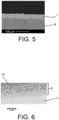
- layer 1 according to the invention can be applied to a layer 2 having a columnar microstructure obtained by EB-PVD (layer 8 in Figure 5 ).
- layer 2 has a thermal barrier and/or environmental barrier function. It also, but not exclusively, ensures good performance in terms of service life and thermal insulation or protection against oxidation and wet corrosion.
- layer 3 acts as a link layer.
- layer 3 may comprise an oxide layer obtained by oxidation of the elements of layer 3, as described above.
- layer 3 may be an aluminoforming layer, i.e. the oxidation of layer 3 may advantageously produce an ⁇ -alumina layer.
- layer 4 is part of a part or an element of a part made of a material chosen from metal alloys, such as metal superalloys, ceramic matrix composites (CMC), and combinations and/or mixtures of these materials.
- This material of layer 4 may in particular be chosen from AM1, René, and CMSX ® -4 superalloys.
- layer 1 according to the invention can be applied to the surface of a layer 5.
- This layer 5 can include independently and/or in combination layers 2, 3, 4.
- layers 2 and 3 and/or layer 5 allow, but not exclusively, to provide a thermal and/or environmental barrier function. They also allow, but not exclusively, to provide good performance in terms of service life and thermal insulation or protection against oxidation and wet corrosion.
- the addition of layer 1 according to the invention does not degrade the performance of the systems, described in the Figures 1 and 2 , on which it is applied.
- the microstructure of layer 1 has a homogeneous and/or cracked morphology, but not exclusively, whether it is produced on layer 2 or layer 5 and this regardless of the microstructure and/or the composition of layer 2 or layer 5.
- Layer 1 according to the invention reacts with the CMAS at high temperature, more precisely at a temperature higher than the melting temperature of the CMAS, to form a reactive zone 9 ( Figure 6 ) beyond which the penetration of CMAS within layer 1 is stopped and/or limited.
- zone 9 is composed of reaction products between the CMAS and layer 1 including, but not limited to, apatite and/or anorthite and/or zirconia phases and/or other reaction products and or combinations and/or mixtures of these phases.
- a layer 1 according to the invention is produced, by the method according to the invention, it is possible, prior to coating the substrate (including layers 2 to 4 of the Figure 1 and/or layer 5 of the Figure 2 ) by layer 1, prepare and/or clean the surface to be coated in order to remove residues and/or contaminants (inorganic and/or organic) which would be likely to prevent deposition and/or degrade adhesion and/or affect the microstructure.
- the surface preparation may be the formation of a surface roughness by sandblasting, the oxidation of the substrate to generate a thin oxide layer and/or a combination of these preparation methods.
- suspensions of ceramic particles in ethanol are first prepared by suspending ceramic particles in ethanol to obtain suspensions having a ceramic concentration of 12% by mass.
- the layer is made with an Oerlikon-Metco ® Triplex Pro200 torch, with a distance between the torch outlet and the 70 mm substrate, using a plasma gas mixture consisting of 80% by volume argon and 20% by volume helium.
- Example 5 the layer is made with an Oerlikon-Metco ® Triplex Pro200 torch, with a distance between the torch outlet and the substrate of 60 mm, using a plasma gas mixture consisting of 80% by volume of argon and 20% by volume of helium.
- Example 6 the layer is made with an Oerlikon-Metco ® F4-VB type torch, with a distance between the torch outlet and the substrate of 50 mm, using a plasma gas mixture consisting of 62% by volume of argon and 38% by volume of helium.
- an anti-CMAS layer according to the invention is prepared by the method according to the invention (see Figure 3 ).
- the anti-CMAS layer 1 consisting of Gd 2 Zr 2 O 7 , is prepared on the surface of a columnar, porous YSZ layer 6 obtained by an SPS process.
- the anti-CMAS layer is prepared by an SPS process using a suspension containing initial particles having a d 90 of less than 10 ⁇ m, namely a d 90 of 7 ⁇ m, and a d 50 of greater than or equal to 1 ⁇ m, namely 3 ⁇ m.
- the sample thus prepared consisting of the anti-CMAS layer on the substrate falls within the framework of the system represented in the Figures 1 and 2 .
- FIG. 3 is a backscattered electron scanning electron microscope (SEM) micrograph of a polished section of the sample prepared in this example.
- an anti-CMAS layer according to the invention is prepared by the method according to the invention.
- the anti-CMAS layer 1 consisting of Gd 2 Zr 2 O 7 is prepared on the surface of a columnar, compact, porous YSZ layer 7 obtained by an SPS process.
- the anti-CMAS layer is prepared by an SPS process using a suspension containing initial particles having a d 90 of less than 10 ⁇ m, namely a d 90 of 7 ⁇ m, and a d 50 of greater than or equal to 1 ⁇ m, namely 3 ⁇ m.
- the sample thus prepared consisting of the anti-CMAS layer on the substrate falls within the framework of the system represented in the Figures 1 and 2 .
- FIG. 4 is a backscattered electron scanning electron microscope (SEM) micrograph of a polished section of the sample prepared in this example.
- an anti-CMAS layer according to the invention is prepared by the method according to the invention.
- the anti-CMAS layer 1 consisting of Gd 2 Zr 2 O 7 is prepared on the surface of a columnar YSZ layer 8 obtained by an EB-PVD process.
- the anti-CMAS layer is prepared by an SPS process using a suspension containing initial particles having a d 90 of less than 10 ⁇ m, namely a d 90 of 7 ⁇ m, and a d 50 of greater than or equal to 1 ⁇ m, namely 3 ⁇ m.
- the sample thus prepared consisting of the anti-CMAS layer on the substrate falls within the framework of the system represented in the Figures 1 and 2 .
- FIG. 5 is a backscattered electron scanning electron microscope (SEM) micrograph of a polished section of the sample prepared in this example.
- an anti-CMAS layer according to the invention is prepared by the method according to the invention (see Figure 9A after infiltration by CMAS).
- the anti-CMAS layer 13 consisting of Gd 2 Zr 2 O 7 , is obtained by SPS using a suspension containing Gd 2 Zr 2 O 7 particles having a d 90 of 7 ⁇ m and a d 50 of 3 ⁇ m.
- the layer is produced on a self-supporting substrate 11 in yttria zirconia stabilized in a t' phase and obtained by APS.
- an anti-CMAS layer according to the invention is prepared by the method according to the invention (see Figure 9B after infiltration by CMAS).
- the anti-CMAS layer 14 consisting of Gd 2 Zr 2 O 7 , is obtained by SPS using a suspension containing Gd 2 Zr 2 O 7 particles having a d 90 of 4.95 ⁇ m and a d 50 of 1.01 ⁇ m.
- the layer is produced on a self-supporting substrate 11 made of yttria-containing zirconia stabilized in a t' phase and obtained by APS.
- an anti-CMAS layer not in accordance with the invention is prepared by a process not in accordance with the invention (see Figure 9C after infiltration by CMAS).
- the anti-CMAS layer 15 consisting of Gd 2 Zr 2 O 7 , is obtained by SPS using a suspension not in accordance with the invention, containing particles of Gd 2 Zr 2 O 7 having a d 90 of 0.89 ⁇ m and a d 50 of 0.41 ⁇ m.
- the layer is produced on a self-supporting substrate 11 made of yttria-containing zirconia stabilized in a t' phase and obtained by APS.
- CMAS 23.5% CaO - 15.0% Al 2 O 3 - 61.5% SiOz - 0% MgO (in % by mass) is deposited on the surface of each of the samples (30 mg/cm 2 ). The sample is heated at 1250 °C for 1 h.
- each of the anti-CMAS layers has reacted and leaves a drop of solidified CMAS on the surface of the sample.
- EDS Electronic Dispersive Spectroscopy
- a CMAS infiltration test is carried out according to the protocol described above, on the sample prepared in Example 3, and the sample is observed after infiltration.
- FIG. 6 is a backscattered electron scanning electron microscope (SEM) micrograph of a polished section of the anti-CMAS layer 1 obtained by SPS in example 3 on the surface of a columnar YSZ layer 8 obtained by EB-PVD.
- SEM backscattered electron scanning electron microscope
- the observation carried out after infiltration by the CMAS reveals on the surface the solidified CMAS 10 and a reaction zone 9 comprising the reaction products between the CMAS and layer 1.
- a CMAS infiltration test is performed according to the protocol described above, on the sample prepared in Example 4, and the sample is observed after CMAS infiltration.
- FIG. 7A is a micrograph taken with a scanning electron microscope (SEM) using backscattered electrons
- the Figure 7B is an EDS (" Energy Dispersive " in English) analysis of silicon from a polished section of the anti-CMAS layer 1 (13) obtained by SPS in example 4 on the surface of a YSZ layer 11 obtained by APS.
- the observation carried out after infiltration of CMAS reveals on the surface the solidified CMAS 10 and a reaction zone 9 comprising the reaction products between the CMAS and layer 1.
- the lighter zone on the EDS image corresponds either to the solidified CMAS 10 or to the reaction zone 9.
- FIG. 8A is another micrograph made with a scanning electron microscope (SEM) using backscattered electrons
- the Figure 8B is another silicon EDS analysis of a polished section of the anti-CMAS layer 1 obtained by SPS in Example 4 on the surface of an YSZ layer 11 obtained by APS.
- the observation is here carried out in an area presenting a crack 12 after CMAS infiltration and reveals on the surface the solidified CMAS 10 and a reaction zone 9 comprising the reaction products between the CMAS and layer 1(13).
- the lighter zone on the EDS image corresponds either to the solidified CMAS 10, or to the reaction zone 9, or to the degree of penetration within the crack of the CMAS or of the reaction products between the CMAS and layer 1.
- FIG. 9A is yet another backscattered electron scanning electron microscope (SEM) micrograph (left) and silicon EDS analysis (right) of a polished section of a 13 anti-CMAS layer of Gd 2 Zr 2 O 7 obtained in Example 4, by SPS, with initial particles having a d 90 of 7 ⁇ m and a d 50 of 3 ⁇ m. This layer is produced on the surface of a 11 YSZ layer obtained by APS.
- SEM backscattered electron scanning electron microscope
- the observation is carried out in an area presenting a crack after CMAS infiltration and reveals on the surface the solidified CMAS 10 and a reaction zone 9 comprising the reaction products between the CMAS and layer 13.
- the lighter zone on the EDS image corresponds either to the solidified CMAS 10, or to the reaction zone 9, or to the degree of penetration within the crack of the CMAS or of the reaction products between the CMAS and layer 13.
- FIG. 10 is a diffractogram obtained by X-ray diffraction after CMAS infiltration of the anti-CMAS layer 13.
- the analysis shows the presence of the initial material Gd 2 Zr 2 O 7 , of an apatite phase Ca 2 Gd 8 (SiO 4 ) 6 O 2 , of an anorthite phase CaAl 2 (SiO 4 ) 2 and of zirconia.
- a CMAS infiltration test is carried out according to the protocol described above, on the sample prepared in Example 5, and the sample is observed after infiltration.
- FIG. 9B is a backscattered electron scanning electron microscope (SEM) micrograph (left) and silicon EDS analysis (right) of a polished section of a Gd 2 Zr 2 O 7 anti-CMAS layer 14 obtained in Example 5, by SPS with initial particles having a diameter of 4.95 ⁇ m and a dso of 1.01 ⁇ m.
- SEM backscattered electron scanning electron microscope
- This layer is made on the surface of a YSZ layer 11 obtained by APS.
- the observation is made in an area showing cracking after CMAS infiltration and reveals on the surface the solidified CMAS 10 and a reaction zone 9 comprising the reaction products between the CMAS and layer 14.
- the lighter zone on the EDS image corresponds either to the solidified CMAS 10 or to the reaction zone 9 or to the degree of penetration within the crack of the CMAS or of the reaction products between the CMAS and layer 14.
- a CMAS infiltration test is carried out according to the protocol described above, on the sample not in accordance with the invention prepared in example 6, and the sample is observed after infiltration.
- FIG. 9C is a backscattered electron scanning electron microscope (SEM) micrograph (left) and an EDS analysis of silicon (right) of a polished section of the anti-CMAS layer 15 of Gd 2 Zr 2 O 7 obtained in Example 6, by SPS, with initial particles having a d 90 of 0.89 ⁇ m and a d 50 of 0.41 ⁇ m.
- This layer is produced on the surface of a YSZ layer 11 obtained by APS.
- the observation is carried out in an area presenting a crack after CMAS infiltration and reveals on the surface the solidified CMAS 10 and a reaction zone 9 comprising the reaction products between the CMAS and the layer 15.
- the lighter zone on the EDS image corresponds either to the solidified CMAS 10, or to the reaction zone 9, or to the degree of penetration within the cracking of the CMAS or of the reaction products between the CMAS and the layer 15.
- the phases present analyzed by X-ray diffraction include the initial material Gd 2 Zr 2 O 7 , an apatite phase Ca 2 Gd 8 (SiO 4 ) 6 O 2 , an anorthite phase CaAL 2 (SiO 4 ) 2 and zirconia ( Figure 10 ).
- the reactive zone 9 as well as the penetration of CMAS within the anti-CMAS layer is more significant, severe, as the particle sizes decrease.
- layer 15 of example 6 presents a much more significant, severe infiltration than layers 13 and 14 according to the invention ( Figure 9A and Figure 9B ).
- the size of the particles of anti-CMAS material injected into the plasma jet generates a difference in the morphology of the porosity. Indeed, the smallest particles will in particular offer the liquid CMAS a greater number of entry points, and more numerous and direct propagation paths in the thickness of the layer. Thus, in example 6, not in accordance with the invention, “small particles” are used in the suspension, and there is then an infiltration of the coating by the CMAS in the thickness of the coating.
- the reaction kinetics of the CMAS with the material of the layers is faster than the kinetics of infiltration, of penetration, of the CMAS in the porosity of the layers.
- the layers according to the invention because they are prepared with suspensions which have a "large" particle size consequently have a high tortuosity, which slows down the kinetics of penetration, of infiltration of the CMAS.
- the kinetics of penetration of the CMAS in the layers prepared by the process according to the invention is much less fast than the reaction kinetics of CMAS with the layer material which allows the formation of effective blocking phases.
- the anti-CMAS layer allows, by the high tortuosity generated, the formation of the blocking phase and/or blocking phases on the surface and/or at a low depth within the anti-CMAS layer.
- an anti-CMAS layer according to the invention is prepared by the method according to the invention.
- the anti-CMAS layer 21 consisting of Gd 2 Zr 2 O 7 is prepared on the surface of a columnar YSZ layer 8 obtained by an EB-PVD method.
- the anti-CMAS layer is prepared by an SPS process using a suspension containing initial particles having a d 90 of 13.2 ⁇ m and a d 50 greater than or equal to 1 ⁇ m, namely 5.5 ⁇ m.
- YSZ layer 8 is the same as YSZ layer 8 from Example 3 but layer 21 has a different particle size.
- the sample thus prepared consisting of the anti-CMAS layer on the substrate falls within the framework of the system represented in the Figures 1 and 2 .
- FIG. 11 is a backscattered electron scanning electron microscope (SEM) micrograph of a polished section of the sample prepared in this example.
- an anti-CMAS layer according to the invention is prepared by the method according to the invention (see Figure 12 after infiltration by CMAS).
- the anti-CMAS layer 21 consisting of Gd 2 Zr 2 O 7 is obtained by SPS using a suspension containing Gd 2 Zr 2 O 7 particles having a d 90 of 13.2 ⁇ m and a d 50 of 5.5 ⁇ m.
- the layer is produced on a self-supporting substrate 11 in yttria-containing zirconia stabilized in a t' phase and obtained by APS.
- a CMAS infiltration test is carried out according to the protocol described above, on the sample prepared in Example 12, and the sample is observed after infiltration.
- FIG. 12 is a backscattered electron scanning electron microscope (SEM) micrograph of a polished section of the anti-CMAS layer 21 obtained by SPS.
- the observation is carried out after infiltration by the CMAS, and reveals on the surface the solidified CMAS 10 and a reaction zone 9 comprising the reaction products between the CMAS and the layer 21.
Landscapes
- Chemical & Material Sciences (AREA)
- Engineering & Computer Science (AREA)
- Mechanical Engineering (AREA)
- Materials Engineering (AREA)
- Organic Chemistry (AREA)
- Chemical Kinetics & Catalysis (AREA)
- Metallurgy (AREA)
- Plasma & Fusion (AREA)
- Physics & Mathematics (AREA)
- Inorganic Chemistry (AREA)
- Ceramic Engineering (AREA)
- General Engineering & Computer Science (AREA)
- Turbine Rotor Nozzle Sealing (AREA)
- Coating By Spraying Or Casting (AREA)
- Other Surface Treatments For Metallic Materials (AREA)
Applications Claiming Priority (2)
| Application Number | Priority Date | Filing Date | Title |
|---|---|---|---|
| FR1660103A FR3057580B1 (fr) | 2016-10-18 | 2016-10-18 | Procede de revetement d'une surface d'un substrat solide par une couche comprenant un compose ceramique, et substrat revetu ainsi obtenu |
| PCT/FR2017/052868 WO2018073538A1 (fr) | 2016-10-18 | 2017-10-18 | Procede de revetement d'une surface d'un substrat solide par une couche comprenant un compose ceramique, et substrat revetu ainsi obtenu |
Publications (2)
| Publication Number | Publication Date |
|---|---|
| EP3529395A1 EP3529395A1 (fr) | 2019-08-28 |
| EP3529395B1 true EP3529395B1 (fr) | 2024-08-14 |
Family
ID=58347466
Family Applications (1)
| Application Number | Title | Priority Date | Filing Date |
|---|---|---|---|
| EP17797677.6A Active EP3529395B1 (fr) | 2016-10-18 | 2017-10-18 | Procédé de revêtement d'une surface d'un substrat solide par une couche comprenant un composé céramique, et substrat revêtu ainsi obtenu |
Country Status (8)
| Country | Link |
|---|---|
| US (1) | US20190242001A1 (https=) |
| EP (1) | EP3529395B1 (https=) |
| JP (1) | JP7271429B2 (https=) |
| CN (1) | CN109874330B (https=) |
| BR (1) | BR112019007670B1 (https=) |
| FR (1) | FR3057580B1 (https=) |
| RU (1) | RU2761397C2 (https=) |
| WO (1) | WO2018073538A1 (https=) |
Families Citing this family (17)
| Publication number | Priority date | Publication date | Assignee | Title |
|---|---|---|---|---|
| SG10201803000QA (en) | 2017-06-26 | 2019-01-30 | Rolls Royce Corp | High density bond coat for ceramic or ceramic matrix composites |
| WO2019126174A1 (en) * | 2017-12-19 | 2019-06-27 | Oerlikon Metco (Us) Inc. | Erosion and cmas resistant coating for protecting ebc and cmc layers and thermal spray coating method |
| CN108866470A (zh) * | 2018-06-19 | 2018-11-23 | 扬州睿德石油机械有限公司 | 一种大气等离子喷涂合金-陶瓷层状涂层的制备方法 |
| WO2020131929A1 (en) * | 2018-12-18 | 2020-06-25 | Oerlikon Metco (Us) Inc. | Coating for protecting ebc and cmc layers and thermal spray coating method thereof |
| US11673097B2 (en) | 2019-05-09 | 2023-06-13 | Valorbec, Societe En Commandite | Filtration membrane and methods of use and manufacture thereof |
| CN110218965A (zh) * | 2019-05-28 | 2019-09-10 | 沈阳富创精密设备有限公司 | 一种先进陶瓷层的制备方法 |
| CN111850454B (zh) * | 2020-07-30 | 2022-12-16 | 江苏大学 | 一种抗cmas侵蚀的热障涂层及制备方法 |
| KR20230121818A (ko) * | 2020-12-15 | 2023-08-21 | 신에쓰 가가꾸 고교 가부시끼가이샤 | 플라스마 용사용 슬러리, 용사막의 제조 방법, 산화알루미늄용사막 및 용사 부재 |
| AU2022238864B2 (en) * | 2021-03-17 | 2024-08-22 | Oerlikon Metco (Us) Inc. | Chemically complex ceramic abradable sealant materials |
| EP4071267A1 (en) | 2021-04-07 | 2022-10-12 | Treibacher Industrie AG | Suspension for thermal spray coatings |
| EP4071266A1 (en) | 2021-04-07 | 2022-10-12 | Treibacher Industrie AG | Suspension for thermal spray coatings |
| US12111148B2 (en) * | 2021-05-21 | 2024-10-08 | General Electric Company | Component imaging systems, apparatus, and methods |
| CN113461442B (zh) * | 2021-07-22 | 2022-04-15 | 北京航空航天大学 | 一种提高热障涂层抗cmas的方法和一种抗cmas的工件 |
| CN114752881B (zh) * | 2022-03-25 | 2024-03-08 | 华东理工大学 | 一种抗cmas腐蚀热障涂层的制备方法以及由此得到的热障涂层 |
| CN115231953A (zh) * | 2022-07-22 | 2022-10-25 | 燕山大学 | 一种硬质合金基体陶瓷复合材料及其制备方法 |
| CN118726890B (zh) * | 2024-06-06 | 2026-02-03 | 北京工业大学 | 一种抗cmas浸润的仿生热障涂层及制备方法 |
| CN121204592B (zh) * | 2025-11-25 | 2026-02-17 | 北矿新材科技有限公司 | 抗腐蚀与雷达-红外兼容隐身功能一体化涂层及其制备方法 |
Family Cites Families (21)
| Publication number | Priority date | Publication date | Assignee | Title |
|---|---|---|---|---|
| FR2557598B1 (fr) | 1983-12-29 | 1986-11-28 | Armines | Alliage monocristallin a matrice a base de nickel |
| DE102004025798A1 (de) * | 2004-05-26 | 2005-12-22 | Mtu Aero Engines Gmbh | Wärmedämmschichtsystem |
| US20070160859A1 (en) * | 2006-01-06 | 2007-07-12 | General Electric Company | Layered thermal barrier coatings containing lanthanide series oxides for improved resistance to CMAS degradation |
| US7736759B2 (en) | 2006-01-20 | 2010-06-15 | United Technologies Corporation | Yttria-stabilized zirconia coating with a molten silicate resistant outer layer |
| US20090184280A1 (en) | 2008-01-18 | 2009-07-23 | Rolls-Royce Corp. | Low Thermal Conductivity, CMAS-Resistant Thermal Barrier Coatings |
| DE102008007870A1 (de) | 2008-02-06 | 2009-08-13 | Forschungszentrum Jülich GmbH | Wärmedämmschichtsystem sowie Verfahren zu seiner Herstellung |
| US8124252B2 (en) * | 2008-11-25 | 2012-02-28 | Rolls-Royce Corporation | Abradable layer including a rare earth silicate |
| FR2940278B1 (fr) * | 2008-12-24 | 2011-05-06 | Snecma Propulsion Solide | Barriere environnementale pour substrat refractaire contenant du silicium |
| US8443891B2 (en) * | 2009-12-18 | 2013-05-21 | Petro-Hunt, L.L.C. | Methods of fracturing a well using Venturi section |
| US20110151219A1 (en) | 2009-12-21 | 2011-06-23 | Bangalore Nagaraj | Coating Systems for Protection of Substrates Exposed to Hot and Harsh Environments and Coated Articles |
| FR2957358B1 (fr) * | 2010-03-12 | 2012-04-13 | Snecma | Methode de fabrication d'une protection de barriere thermique et revetement multicouche apte a former une barriere thermique |
| US20120034491A1 (en) * | 2010-08-05 | 2012-02-09 | United Technologies Corporation | Cmas resistant tbc coating |
| US20130260132A1 (en) | 2012-04-02 | 2013-10-03 | United Technologies Corporation | Hybrid thermal barrier coating |
| JP5953947B2 (ja) * | 2012-06-04 | 2016-07-20 | 株式会社Ihi | 耐環境被覆されたセラミックス基複合材料部品及びその製造方法 |
| US11047033B2 (en) | 2012-09-05 | 2021-06-29 | Raytheon Technologies Corporation | Thermal barrier coating for gas turbine engine components |
| JP2014240511A (ja) * | 2013-06-11 | 2014-12-25 | 株式会社フジミインコーポレーテッド | 溶射皮膜の製造方法および溶射用材料 |
| US9890089B2 (en) * | 2014-03-11 | 2018-02-13 | General Electric Company | Compositions and methods for thermal spraying a hermetic rare earth environmental barrier coating |
| US20160186580A1 (en) * | 2014-05-20 | 2016-06-30 | United Technologies Corporation | Calcium Magnesium Aluminosilicate (CMAS) Resistant Thermal Barrier Coating and Coating Process Therefor |
| JP6513794B2 (ja) * | 2014-09-18 | 2019-05-15 | エリコン メテコ(ユーエス)インコーポレイテッド | 予備配合された粉末原料 |
| GB2532466B (en) * | 2014-11-19 | 2020-11-25 | Weston Body Hardware Ltd | A paddle latch |
| JP6510824B2 (ja) * | 2015-01-27 | 2019-05-08 | 日本イットリウム株式会社 | 溶射用粉末及び溶射材料 |
-
2016
- 2016-10-18 FR FR1660103A patent/FR3057580B1/fr active Active
-
2017
- 2017-10-18 BR BR112019007670-0A patent/BR112019007670B1/pt not_active IP Right Cessation
- 2017-10-18 JP JP2019541889A patent/JP7271429B2/ja active Active
- 2017-10-18 CN CN201780064708.5A patent/CN109874330B/zh active Active
- 2017-10-18 WO PCT/FR2017/052868 patent/WO2018073538A1/fr not_active Ceased
- 2017-10-18 RU RU2019115140A patent/RU2761397C2/ru active
- 2017-10-18 US US16/341,956 patent/US20190242001A1/en not_active Abandoned
- 2017-10-18 EP EP17797677.6A patent/EP3529395B1/fr active Active
Also Published As
| Publication number | Publication date |
|---|---|
| BR112019007670A2 (pt) | 2019-07-02 |
| BR112019007670B1 (pt) | 2023-04-04 |
| RU2019115140A (ru) | 2020-11-20 |
| RU2761397C2 (ru) | 2021-12-08 |
| JP2019533090A (ja) | 2019-11-14 |
| CA3040347A1 (en) | 2018-04-26 |
| CN109874330B (zh) | 2021-07-16 |
| FR3057580A1 (fr) | 2018-04-20 |
| CN109874330A (zh) | 2019-06-11 |
| RU2019115140A3 (https=) | 2021-04-02 |
| JP7271429B2 (ja) | 2023-05-11 |
| EP3529395A1 (fr) | 2019-08-28 |
| WO2018073538A1 (fr) | 2018-04-26 |
| FR3057580B1 (fr) | 2023-12-29 |
| US20190242001A1 (en) | 2019-08-08 |
Similar Documents
| Publication | Publication Date | Title |
|---|---|---|
| EP3529395B1 (fr) | Procédé de revêtement d'une surface d'un substrat solide par une couche comprenant un composé céramique, et substrat revêtu ainsi obtenu | |
| JP5554488B2 (ja) | 遮熱コーティング用アルミナ系保護皮膜 | |
| CA2792518C (fr) | Methode de fabrication d'une protecton de barriere thermique et revetement multicouche apte a former une barriere thermique | |
| CA2913974C (fr) | Barriere environnementale pour substrat refractaire contenant du silicium | |
| EP3638885B1 (fr) | Pièce de turbomachine revêtue et procédé de fabrication associé | |
| EP3638884B1 (fr) | Pièce de turbomachine revêtue et procédé de fabrication associé | |
| US20160273087A1 (en) | Structure or component for high temperature applications, as well as methods and apparatus for producing same | |
| WO2018087452A1 (fr) | Piece de turbomachine revetue d'une barriere thermique et procede pour l'obtenir. | |
| EP3732352B1 (fr) | Pièce revêtue d'une composition de protection contre les cmas à fissuration controlée, et procédé de traitement correspondant | |
| EP1522533A1 (fr) | Cible destinée à être évaporée sous faisceau d'électrons, son procédé de fabrication, barrière thermique et revêtement obtenus à partir d'une cible, et pièce mécanique comportant un tel revêtement | |
| Bakkar et al. | A new approach to protect and extend longevity of the thermal barrier coating by an impermeable layer of silicon nitride | |
| FR2999457A1 (fr) | Procede de revetement d'un substrat par un materiau abradable ceramique, et revetement ainsi obtenu. | |
| WO2017080948A1 (fr) | Revêtement céramique multicouche de protection thermique à haute température, notamment pour application aéronautique, et son procédé de fabrication | |
| FR3139567A1 (fr) | Procédé de fabrication d’une éprouvette de caractérisation | |
| CA3040347C (en) | Method for coating a surface of a solid substrate with a layer comprising a ceramic compound, and coated substrate thus obtained | |
| Di Iorio | Development of novel environmental barrier coatings for next generation gas turbine engines | |
| FR3070400A1 (fr) | Couche protectrice resistante aux materiaux du type cmas | |
| CA2508821A1 (fr) | Procede de fabrication ou de reparation d'un revetement sur un substrat metallique | |
| WO2025083363A1 (fr) | Procédé de revêtement d'un substrat en matériau composite à matrice céramique par au moins un revêtement, et pièce correspondante | |
| Uhlmann et al. | Ultra High Temperature Ceramic Coatings For Environmental Protection of Cf/SiC Composites |
Legal Events
| Date | Code | Title | Description |
|---|---|---|---|
| STAA | Information on the status of an ep patent application or granted ep patent |
Free format text: STATUS: UNKNOWN |
|
| STAA | Information on the status of an ep patent application or granted ep patent |
Free format text: STATUS: THE INTERNATIONAL PUBLICATION HAS BEEN MADE |
|
| PUAI | Public reference made under article 153(3) epc to a published international application that has entered the european phase |
Free format text: ORIGINAL CODE: 0009012 |
|
| STAA | Information on the status of an ep patent application or granted ep patent |
Free format text: STATUS: REQUEST FOR EXAMINATION WAS MADE |
|
| 17P | Request for examination filed |
Effective date: 20190419 |
|
| AK | Designated contracting states |
Kind code of ref document: A1 Designated state(s): AL AT BE BG CH CY CZ DE DK EE ES FI FR GB GR HR HU IE IS IT LI LT LU LV MC MK MT NL NO PL PT RO RS SE SI SK SM TR |
|
| AX | Request for extension of the european patent |
Extension state: BA ME |
|
| DAV | Request for validation of the european patent (deleted) | ||
| DAX | Request for extension of the european patent (deleted) | ||
| STAA | Information on the status of an ep patent application or granted ep patent |
Free format text: STATUS: EXAMINATION IS IN PROGRESS |
|
| 17Q | First examination report despatched |
Effective date: 20210712 |
|
| GRAP | Despatch of communication of intention to grant a patent |
Free format text: ORIGINAL CODE: EPIDOSNIGR1 |
|
| STAA | Information on the status of an ep patent application or granted ep patent |
Free format text: STATUS: GRANT OF PATENT IS INTENDED |
|
| RIC1 | Information provided on ipc code assigned before grant |
Ipc: F01D 5/28 20060101ALI20240212BHEP Ipc: C23C 4/134 20160101ALI20240212BHEP Ipc: C23C 4/11 20160101ALI20240212BHEP Ipc: C23C 28/00 20060101ALI20240212BHEP Ipc: C23C 28/04 20060101ALI20240212BHEP Ipc: C23C 4/12 20160101ALI20240212BHEP Ipc: C23C 4/10 20160101AFI20240212BHEP |
|
| INTG | Intention to grant announced |
Effective date: 20240312 |
|
| GRAS | Grant fee paid |
Free format text: ORIGINAL CODE: EPIDOSNIGR3 |
|
| GRAA | (expected) grant |
Free format text: ORIGINAL CODE: 0009210 |
|
| STAA | Information on the status of an ep patent application or granted ep patent |
Free format text: STATUS: THE PATENT HAS BEEN GRANTED |
|
| AK | Designated contracting states |
Kind code of ref document: B1 Designated state(s): AL AT BE BG CH CY CZ DE DK EE ES FI FR GB GR HR HU IE IS IT LI LT LU LV MC MK MT NL NO PL PT RO RS SE SI SK SM TR |
|
| REG | Reference to a national code |
Ref country code: GB Ref legal event code: FG4D Free format text: NOT ENGLISH |
|
| REG | Reference to a national code |
Ref country code: CH Ref legal event code: EP |
|
| REG | Reference to a national code |
Ref country code: DE Ref legal event code: R096 Ref document number: 602017084094 Country of ref document: DE |
|
| REG | Reference to a national code |
Ref country code: IE Ref legal event code: FG4D Free format text: LANGUAGE OF EP DOCUMENT: FRENCH |
|
| RAP4 | Party data changed (patent owner data changed or rights of a patent transferred) |
Owner name: SAFRAN Owner name: COMMISSARIAT A L'ENERGIE ATOMIQUE ET AUX ENERGIESALTERNATIVES |
|
| REG | Reference to a national code |
Ref country code: LT Ref legal event code: MG9D |
|
| REG | Reference to a national code |
Ref country code: NL Ref legal event code: MP Effective date: 20240814 |
|
| PG25 | Lapsed in a contracting state [announced via postgrant information from national office to epo] |
Ref country code: NO Free format text: LAPSE BECAUSE OF FAILURE TO SUBMIT A TRANSLATION OF THE DESCRIPTION OR TO PAY THE FEE WITHIN THE PRESCRIBED TIME-LIMIT Effective date: 20241114 |
|
| REG | Reference to a national code |
Ref country code: AT Ref legal event code: MK05 Ref document number: 1713353 Country of ref document: AT Kind code of ref document: T Effective date: 20240814 |
|
| PG25 | Lapsed in a contracting state [announced via postgrant information from national office to epo] |
Ref country code: FI Free format text: LAPSE BECAUSE OF FAILURE TO SUBMIT A TRANSLATION OF THE DESCRIPTION OR TO PAY THE FEE WITHIN THE PRESCRIBED TIME-LIMIT Effective date: 20240814 Ref country code: GR Free format text: LAPSE BECAUSE OF FAILURE TO SUBMIT A TRANSLATION OF THE DESCRIPTION OR TO PAY THE FEE WITHIN THE PRESCRIBED TIME-LIMIT Effective date: 20241115 Ref country code: NL Free format text: LAPSE BECAUSE OF FAILURE TO SUBMIT A TRANSLATION OF THE DESCRIPTION OR TO PAY THE FEE WITHIN THE PRESCRIBED TIME-LIMIT Effective date: 20240814 Ref country code: PT Free format text: LAPSE BECAUSE OF FAILURE TO SUBMIT A TRANSLATION OF THE DESCRIPTION OR TO PAY THE FEE WITHIN THE PRESCRIBED TIME-LIMIT Effective date: 20241216 Ref country code: PL Free format text: LAPSE BECAUSE OF FAILURE TO SUBMIT A TRANSLATION OF THE DESCRIPTION OR TO PAY THE FEE WITHIN THE PRESCRIBED TIME-LIMIT Effective date: 20240814 |
|
| PG25 | Lapsed in a contracting state [announced via postgrant information from national office to epo] |
Ref country code: BG Free format text: LAPSE BECAUSE OF FAILURE TO SUBMIT A TRANSLATION OF THE DESCRIPTION OR TO PAY THE FEE WITHIN THE PRESCRIBED TIME-LIMIT Effective date: 20240814 |
|
| PG25 | Lapsed in a contracting state [announced via postgrant information from national office to epo] |
Ref country code: LV Free format text: LAPSE BECAUSE OF FAILURE TO SUBMIT A TRANSLATION OF THE DESCRIPTION OR TO PAY THE FEE WITHIN THE PRESCRIBED TIME-LIMIT Effective date: 20240814 |
|
| PG25 | Lapsed in a contracting state [announced via postgrant information from national office to epo] |
Ref country code: AT Free format text: LAPSE BECAUSE OF FAILURE TO SUBMIT A TRANSLATION OF THE DESCRIPTION OR TO PAY THE FEE WITHIN THE PRESCRIBED TIME-LIMIT Effective date: 20240814 Ref country code: IS Free format text: LAPSE BECAUSE OF FAILURE TO SUBMIT A TRANSLATION OF THE DESCRIPTION OR TO PAY THE FEE WITHIN THE PRESCRIBED TIME-LIMIT Effective date: 20241214 |
|
| PG25 | Lapsed in a contracting state [announced via postgrant information from national office to epo] |
Ref country code: HR Free format text: LAPSE BECAUSE OF FAILURE TO SUBMIT A TRANSLATION OF THE DESCRIPTION OR TO PAY THE FEE WITHIN THE PRESCRIBED TIME-LIMIT Effective date: 20240814 |
|
| PG25 | Lapsed in a contracting state [announced via postgrant information from national office to epo] |
Ref country code: RS Free format text: LAPSE BECAUSE OF FAILURE TO SUBMIT A TRANSLATION OF THE DESCRIPTION OR TO PAY THE FEE WITHIN THE PRESCRIBED TIME-LIMIT Effective date: 20241114 Ref country code: ES Free format text: LAPSE BECAUSE OF FAILURE TO SUBMIT A TRANSLATION OF THE DESCRIPTION OR TO PAY THE FEE WITHIN THE PRESCRIBED TIME-LIMIT Effective date: 20240814 |
|
| PG25 | Lapsed in a contracting state [announced via postgrant information from national office to epo] |
Ref country code: RS Free format text: LAPSE BECAUSE OF FAILURE TO SUBMIT A TRANSLATION OF THE DESCRIPTION OR TO PAY THE FEE WITHIN THE PRESCRIBED TIME-LIMIT Effective date: 20241114 Ref country code: PT Free format text: LAPSE BECAUSE OF FAILURE TO SUBMIT A TRANSLATION OF THE DESCRIPTION OR TO PAY THE FEE WITHIN THE PRESCRIBED TIME-LIMIT Effective date: 20241216 Ref country code: PL Free format text: LAPSE BECAUSE OF FAILURE TO SUBMIT A TRANSLATION OF THE DESCRIPTION OR TO PAY THE FEE WITHIN THE PRESCRIBED TIME-LIMIT Effective date: 20240814 Ref country code: NO Free format text: LAPSE BECAUSE OF FAILURE TO SUBMIT A TRANSLATION OF THE DESCRIPTION OR TO PAY THE FEE WITHIN THE PRESCRIBED TIME-LIMIT Effective date: 20241114 Ref country code: NL Free format text: LAPSE BECAUSE OF FAILURE TO SUBMIT A TRANSLATION OF THE DESCRIPTION OR TO PAY THE FEE WITHIN THE PRESCRIBED TIME-LIMIT Effective date: 20240814 Ref country code: LV Free format text: LAPSE BECAUSE OF FAILURE TO SUBMIT A TRANSLATION OF THE DESCRIPTION OR TO PAY THE FEE WITHIN THE PRESCRIBED TIME-LIMIT Effective date: 20240814 Ref country code: IS Free format text: LAPSE BECAUSE OF FAILURE TO SUBMIT A TRANSLATION OF THE DESCRIPTION OR TO PAY THE FEE WITHIN THE PRESCRIBED TIME-LIMIT Effective date: 20241214 Ref country code: HR Free format text: LAPSE BECAUSE OF FAILURE TO SUBMIT A TRANSLATION OF THE DESCRIPTION OR TO PAY THE FEE WITHIN THE PRESCRIBED TIME-LIMIT Effective date: 20240814 Ref country code: GR Free format text: LAPSE BECAUSE OF FAILURE TO SUBMIT A TRANSLATION OF THE DESCRIPTION OR TO PAY THE FEE WITHIN THE PRESCRIBED TIME-LIMIT Effective date: 20241115 Ref country code: FI Free format text: LAPSE BECAUSE OF FAILURE TO SUBMIT A TRANSLATION OF THE DESCRIPTION OR TO PAY THE FEE WITHIN THE PRESCRIBED TIME-LIMIT Effective date: 20240814 Ref country code: ES Free format text: LAPSE BECAUSE OF FAILURE TO SUBMIT A TRANSLATION OF THE DESCRIPTION OR TO PAY THE FEE WITHIN THE PRESCRIBED TIME-LIMIT Effective date: 20240814 Ref country code: BG Free format text: LAPSE BECAUSE OF FAILURE TO SUBMIT A TRANSLATION OF THE DESCRIPTION OR TO PAY THE FEE WITHIN THE PRESCRIBED TIME-LIMIT Effective date: 20240814 Ref country code: AT Free format text: LAPSE BECAUSE OF FAILURE TO SUBMIT A TRANSLATION OF THE DESCRIPTION OR TO PAY THE FEE WITHIN THE PRESCRIBED TIME-LIMIT Effective date: 20240814 |
|
| PG25 | Lapsed in a contracting state [announced via postgrant information from national office to epo] |
Ref country code: RO Free format text: LAPSE BECAUSE OF FAILURE TO SUBMIT A TRANSLATION OF THE DESCRIPTION OR TO PAY THE FEE WITHIN THE PRESCRIBED TIME-LIMIT Effective date: 20240814 Ref country code: SM Free format text: LAPSE BECAUSE OF FAILURE TO SUBMIT A TRANSLATION OF THE DESCRIPTION OR TO PAY THE FEE WITHIN THE PRESCRIBED TIME-LIMIT Effective date: 20240814 Ref country code: DK Free format text: LAPSE BECAUSE OF FAILURE TO SUBMIT A TRANSLATION OF THE DESCRIPTION OR TO PAY THE FEE WITHIN THE PRESCRIBED TIME-LIMIT Effective date: 20240814 |
|
| PG25 | Lapsed in a contracting state [announced via postgrant information from national office to epo] |
Ref country code: EE Free format text: LAPSE BECAUSE OF FAILURE TO SUBMIT A TRANSLATION OF THE DESCRIPTION OR TO PAY THE FEE WITHIN THE PRESCRIBED TIME-LIMIT Effective date: 20240814 |
|
| PG25 | Lapsed in a contracting state [announced via postgrant information from national office to epo] |
Ref country code: CZ Free format text: LAPSE BECAUSE OF FAILURE TO SUBMIT A TRANSLATION OF THE DESCRIPTION OR TO PAY THE FEE WITHIN THE PRESCRIBED TIME-LIMIT Effective date: 20240814 |
|
| PG25 | Lapsed in a contracting state [announced via postgrant information from national office to epo] |
Ref country code: IT Free format text: LAPSE BECAUSE OF FAILURE TO SUBMIT A TRANSLATION OF THE DESCRIPTION OR TO PAY THE FEE WITHIN THE PRESCRIBED TIME-LIMIT Effective date: 20240814 Ref country code: SK Free format text: LAPSE BECAUSE OF FAILURE TO SUBMIT A TRANSLATION OF THE DESCRIPTION OR TO PAY THE FEE WITHIN THE PRESCRIBED TIME-LIMIT Effective date: 20240814 |
|
| REG | Reference to a national code |
Ref country code: DE Ref legal event code: R097 Ref document number: 602017084094 Country of ref document: DE |
|
| REG | Reference to a national code |
Ref country code: CH Ref legal event code: PL |
|
| PLBE | No opposition filed within time limit |
Free format text: ORIGINAL CODE: 0009261 |
|
| STAA | Information on the status of an ep patent application or granted ep patent |
Free format text: STATUS: NO OPPOSITION FILED WITHIN TIME LIMIT |
|
| PG25 | Lapsed in a contracting state [announced via postgrant information from national office to epo] |
Ref country code: MC Free format text: LAPSE BECAUSE OF FAILURE TO SUBMIT A TRANSLATION OF THE DESCRIPTION OR TO PAY THE FEE WITHIN THE PRESCRIBED TIME-LIMIT Effective date: 20240814 |
|
| PG25 | Lapsed in a contracting state [announced via postgrant information from national office to epo] |
Ref country code: LU Free format text: LAPSE BECAUSE OF NON-PAYMENT OF DUE FEES Effective date: 20241018 Ref country code: BE Free format text: LAPSE BECAUSE OF NON-PAYMENT OF DUE FEES Effective date: 20241031 |
|
| 26N | No opposition filed |
Effective date: 20250515 |
|
| PG25 | Lapsed in a contracting state [announced via postgrant information from national office to epo] |
Ref country code: CH Free format text: LAPSE BECAUSE OF NON-PAYMENT OF DUE FEES Effective date: 20241031 |
|
| REG | Reference to a national code |
Ref country code: BE Ref legal event code: MM Effective date: 20241031 |
|
| PG25 | Lapsed in a contracting state [announced via postgrant information from national office to epo] |
Ref country code: SE Free format text: LAPSE BECAUSE OF FAILURE TO SUBMIT A TRANSLATION OF THE DESCRIPTION OR TO PAY THE FEE WITHIN THE PRESCRIBED TIME-LIMIT Effective date: 20240814 |
|
| PG25 | Lapsed in a contracting state [announced via postgrant information from national office to epo] |
Ref country code: IE Free format text: LAPSE BECAUSE OF NON-PAYMENT OF DUE FEES Effective date: 20241018 |
|
| PGFP | Annual fee paid to national office [announced via postgrant information from national office to epo] |
Ref country code: DE Payment date: 20251020 Year of fee payment: 9 |
|
| PGFP | Annual fee paid to national office [announced via postgrant information from national office to epo] |
Ref country code: GB Payment date: 20251029 Year of fee payment: 9 |
|
| PGFP | Annual fee paid to national office [announced via postgrant information from national office to epo] |
Ref country code: FR Payment date: 20251023 Year of fee payment: 9 |
|
| PG25 | Lapsed in a contracting state [announced via postgrant information from national office to epo] |
Ref country code: CY Free format text: LAPSE BECAUSE OF FAILURE TO SUBMIT A TRANSLATION OF THE DESCRIPTION OR TO PAY THE FEE WITHIN THE PRESCRIBED TIME-LIMIT; INVALID AB INITIO Effective date: 20171018 |
|
| PG25 | Lapsed in a contracting state [announced via postgrant information from national office to epo] |
Ref country code: HU Free format text: LAPSE BECAUSE OF FAILURE TO SUBMIT A TRANSLATION OF THE DESCRIPTION OR TO PAY THE FEE WITHIN THE PRESCRIBED TIME-LIMIT; INVALID AB INITIO Effective date: 20171018 |