EP3529177B2 - Storage systems and methods - Google Patents
Storage systems and methods Download PDFInfo
- Publication number
- EP3529177B2 EP3529177B2 EP17790741.7A EP17790741A EP3529177B2 EP 3529177 B2 EP3529177 B2 EP 3529177B2 EP 17790741 A EP17790741 A EP 17790741A EP 3529177 B2 EP3529177 B2 EP 3529177B2
- Authority
- EP
- European Patent Office
- Prior art keywords
- containers
- container
- storage system
- stack
- load handling
- Prior art date
- Legal status (The legal status is an assumption and is not a legal conclusion. Google has not performed a legal analysis and makes no representation as to the accuracy of the status listed.)
- Active
Links
- 238000003860 storage Methods 0.000 title claims description 79
- 238000000034 method Methods 0.000 title description 6
- 238000004891 communication Methods 0.000 claims description 25
- 238000012544 monitoring process Methods 0.000 claims description 16
- 238000001816 cooling Methods 0.000 claims description 15
- 239000012530 fluid Substances 0.000 claims description 13
- 238000010438 heat treatment Methods 0.000 claims description 9
- 230000006870 function Effects 0.000 claims description 6
- 238000004364 calculation method Methods 0.000 claims description 4
- 238000012795 verification Methods 0.000 claims description 2
- 239000007789 gas Substances 0.000 description 7
- 238000012545 processing Methods 0.000 description 6
- 230000008901 benefit Effects 0.000 description 5
- 235000013399 edible fruits Nutrition 0.000 description 5
- 230000007246 mechanism Effects 0.000 description 5
- 238000000638 solvent extraction Methods 0.000 description 5
- 230000005070 ripening Effects 0.000 description 3
- XLYOFNOQVPJJNP-UHFFFAOYSA-N water Substances O XLYOFNOQVPJJNP-UHFFFAOYSA-N 0.000 description 3
- 230000005540 biological transmission Effects 0.000 description 2
- 238000013500 data storage Methods 0.000 description 2
- 230000000694 effects Effects 0.000 description 2
- 230000006698 induction Effects 0.000 description 2
- 239000007788 liquid Substances 0.000 description 2
- 230000003287 optical effect Effects 0.000 description 2
- 238000011084 recovery Methods 0.000 description 2
- 238000004088 simulation Methods 0.000 description 2
- 239000000779 smoke Substances 0.000 description 2
- 238000012546 transfer Methods 0.000 description 2
- OKTJSMMVPCPJKN-UHFFFAOYSA-N Carbon Chemical compound [C] OKTJSMMVPCPJKN-UHFFFAOYSA-N 0.000 description 1
- 230000003213 activating effect Effects 0.000 description 1
- 229910052799 carbon Inorganic materials 0.000 description 1
- 238000006243 chemical reaction Methods 0.000 description 1
- 235000019219 chocolate Nutrition 0.000 description 1
- 238000013461 design Methods 0.000 description 1
- 238000011161 development Methods 0.000 description 1
- 230000018109 developmental process Effects 0.000 description 1
- 238000010586 diagram Methods 0.000 description 1
- 238000009826 distribution Methods 0.000 description 1
- 230000005674 electromagnetic induction Effects 0.000 description 1
- 239000000835 fiber Substances 0.000 description 1
- 230000004345 fruit ripening Effects 0.000 description 1
- 238000007689 inspection Methods 0.000 description 1
- 238000004519 manufacturing process Methods 0.000 description 1
- 238000002844 melting Methods 0.000 description 1
- 230000008018 melting Effects 0.000 description 1
- 239000002184 metal Substances 0.000 description 1
- 238000000465 moulding Methods 0.000 description 1
- 230000008569 process Effects 0.000 description 1
- 238000001243 protein synthesis Methods 0.000 description 1
- 230000008439 repair process Effects 0.000 description 1
- 238000007789 sealing Methods 0.000 description 1
- 239000002002 slurry Substances 0.000 description 1
- 238000012876 topography Methods 0.000 description 1
- 230000014616 translation Effects 0.000 description 1
- 230000001960 triggered effect Effects 0.000 description 1
- 238000005303 weighing Methods 0.000 description 1
Images


Classifications
-
- B—PERFORMING OPERATIONS; TRANSPORTING
- B65—CONVEYING; PACKING; STORING; HANDLING THIN OR FILAMENTARY MATERIAL
- B65G—TRANSPORT OR STORAGE DEVICES, e.g. CONVEYORS FOR LOADING OR TIPPING, SHOP CONVEYOR SYSTEMS OR PNEUMATIC TUBE CONVEYORS
- B65G1/00—Storing articles, individually or in orderly arrangement, in warehouses or magazines
- B65G1/02—Storage devices
- B65G1/04—Storage devices mechanical
- B65G1/0464—Storage devices mechanical with access from above
-
- B—PERFORMING OPERATIONS; TRANSPORTING
- B65—CONVEYING; PACKING; STORING; HANDLING THIN OR FILAMENTARY MATERIAL
- B65G—TRANSPORT OR STORAGE DEVICES, e.g. CONVEYORS FOR LOADING OR TIPPING, SHOP CONVEYOR SYSTEMS OR PNEUMATIC TUBE CONVEYORS
- B65G1/00—Storing articles, individually or in orderly arrangement, in warehouses or magazines
- B65G1/02—Storage devices
- B65G1/04—Storage devices mechanical
- B65G1/0478—Storage devices mechanical for matrix-arrangements
-
- B—PERFORMING OPERATIONS; TRANSPORTING
- B65—CONVEYING; PACKING; STORING; HANDLING THIN OR FILAMENTARY MATERIAL
- B65G—TRANSPORT OR STORAGE DEVICES, e.g. CONVEYORS FOR LOADING OR TIPPING, SHOP CONVEYOR SYSTEMS OR PNEUMATIC TUBE CONVEYORS
- B65G1/00—Storing articles, individually or in orderly arrangement, in warehouses or magazines
- B65G1/02—Storage devices
- B65G1/04—Storage devices mechanical
- B65G1/06—Storage devices mechanical with means for presenting articles for removal at predetermined position or level
- B65G1/065—Storage devices mechanical with means for presenting articles for removal at predetermined position or level with self propelled cars
-
- B—PERFORMING OPERATIONS; TRANSPORTING
- B65—CONVEYING; PACKING; STORING; HANDLING THIN OR FILAMENTARY MATERIAL
- B65G—TRANSPORT OR STORAGE DEVICES, e.g. CONVEYORS FOR LOADING OR TIPPING, SHOP CONVEYOR SYSTEMS OR PNEUMATIC TUBE CONVEYORS
- B65G1/00—Storing articles, individually or in orderly arrangement, in warehouses or magazines
- B65G1/02—Storage devices
- B65G1/04—Storage devices mechanical
- B65G1/12—Storage devices mechanical with separate article supports or holders movable in a closed circuit to facilitate insertion or removal of articles the articles being books, documents, forms or the like
- B65G1/127—Storage devices mechanical with separate article supports or holders movable in a closed circuit to facilitate insertion or removal of articles the articles being books, documents, forms or the like the circuit being confined in a vertical plane
-
- B—PERFORMING OPERATIONS; TRANSPORTING
- B65—CONVEYING; PACKING; STORING; HANDLING THIN OR FILAMENTARY MATERIAL
- B65G—TRANSPORT OR STORAGE DEVICES, e.g. CONVEYORS FOR LOADING OR TIPPING, SHOP CONVEYOR SYSTEMS OR PNEUMATIC TUBE CONVEYORS
- B65G1/00—Storing articles, individually or in orderly arrangement, in warehouses or magazines
- B65G1/02—Storage devices
- B65G1/04—Storage devices mechanical
- B65G1/12—Storage devices mechanical with separate article supports or holders movable in a closed circuit to facilitate insertion or removal of articles the articles being books, documents, forms or the like
- B65G1/133—Storage devices mechanical with separate article supports or holders movable in a closed circuit to facilitate insertion or removal of articles the articles being books, documents, forms or the like the circuit being confined in a horizontal plane
-
- B—PERFORMING OPERATIONS; TRANSPORTING
- B65—CONVEYING; PACKING; STORING; HANDLING THIN OR FILAMENTARY MATERIAL
- B65G—TRANSPORT OR STORAGE DEVICES, e.g. CONVEYORS FOR LOADING OR TIPPING, SHOP CONVEYOR SYSTEMS OR PNEUMATIC TUBE CONVEYORS
- B65G1/00—Storing articles, individually or in orderly arrangement, in warehouses or magazines
- B65G1/16—Special arrangements of articles in storage spaces
-
- B—PERFORMING OPERATIONS; TRANSPORTING
- B65—CONVEYING; PACKING; STORING; HANDLING THIN OR FILAMENTARY MATERIAL
- B65G—TRANSPORT OR STORAGE DEVICES, e.g. CONVEYORS FOR LOADING OR TIPPING, SHOP CONVEYOR SYSTEMS OR PNEUMATIC TUBE CONVEYORS
- B65G57/00—Stacking of articles
- B65G57/02—Stacking of articles by adding to the top of the stack
- B65G57/03—Stacking of articles by adding to the top of the stack from above
-
- G—PHYSICS
- G06—COMPUTING; CALCULATING OR COUNTING
- G06F—ELECTRIC DIGITAL DATA PROCESSING
- G06F1/00—Details not covered by groups G06F3/00 - G06F13/00 and G06F21/00
- G06F1/26—Power supply means, e.g. regulation thereof
- G06F1/32—Means for saving power
- G06F1/3203—Power management, i.e. event-based initiation of a power-saving mode
-
- G—PHYSICS
- G06—COMPUTING; CALCULATING OR COUNTING
- G06N—COMPUTING ARRANGEMENTS BASED ON SPECIFIC COMPUTATIONAL MODELS
- G06N5/00—Computing arrangements using knowledge-based models
- G06N5/02—Knowledge representation; Symbolic representation
-
- H—ELECTRICITY
- H04—ELECTRIC COMMUNICATION TECHNIQUE
- H04W—WIRELESS COMMUNICATION NETWORKS
- H04W4/00—Services specially adapted for wireless communication networks; Facilities therefor
- H04W4/80—Services using short range communication, e.g. near-field communication [NFC], radio-frequency identification [RFID] or low energy communication
-
- B—PERFORMING OPERATIONS; TRANSPORTING
- B65—CONVEYING; PACKING; STORING; HANDLING THIN OR FILAMENTARY MATERIAL
- B65G—TRANSPORT OR STORAGE DEVICES, e.g. CONVEYORS FOR LOADING OR TIPPING, SHOP CONVEYOR SYSTEMS OR PNEUMATIC TUBE CONVEYORS
- B65G2201/00—Indexing codes relating to handling devices, e.g. conveyors, characterised by the type of product or load being conveyed or handled
- B65G2201/02—Articles
- B65G2201/0235—Containers
Definitions
- the present invention relates to storage systems. More specifically but not exclusively, it relates to a storage system having storage bins or containers in stacks and robots operating above the stacks to pick, move, remove, or replace containers.
- One known type of system for the storage and retrieval of items in multiple product lines involves arranging storage containers or containers in stacks on top of one another, the stacks being arranged in rows. The storage containers or containers are accessed from above, removing the need for aisles between rows and allowing more containers to be stored in a given space.
- the containers are passive and exist simply to hold the goods. Whilst the identity of a given container may be known and linked to its contents by barcoding for example, the containers in the system have no active components or on board intelligence.
- the containers comprise monitoring and controlling systems to, for example, containers that chill the contents, containers that comprise gas monitoring systems, for example, to monitor for fruit ripening and containers that comprise locating means to enable individual containers to be tracked and traced in port.
- the height of the tube has to be as least as high as the height of the largest stack of containers, so that that the highest stack of containers can be extracted in a single operation. Accordingly, when used in an enclosed space such as a warehouse, the maximum height of the stacks is restricted by the need to accommodate the tube of the load handler.
- EP 1037828 B1 (Autostore) the contents of which are incorporated herein by reference, describes a system in which stacks of containers are arranged within a frame structure.
- a system of this type is illustrated schematically in Figures 1 to 4 of the accompanying drawings.
- Robotic load handling devices can be controllably moved around the stack on a system of tracks on the upper most surface of the stack.
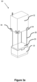
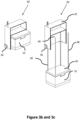
- Figure 3a and 3b are schematic perspective views of one form of a load handling device suitable for use in a robotic picking system from the rear and front, respectively, and Figure 3c is a schematic front perspective view of the load handling device of Figures 3a and 3b lifting a bin or container.
- individual containers within the storage system may be provided with services, in addition to or in place of goods, yet may be removed from the system without loss of data or information stored within the container due to removal of power supplied via, for example the uprights of the storage system .
- individual containers within the storage system may not contain goods but may contain services for provision to other containers or to monitor or control the condition of the system and in this way the integrity of the data contained therein is protected.
- the contents may be continually powered and data flow between containers maintained such that control or monitoring of containers within the system, or data relating to the system stored within memory or processing means within the system, is maintained.
- services and conditions within the containers may be maintained, for example temperature, moisture, lighting or other parameters, as the power and data connections to the container are maintained by virtue of the electrical and or data connections to the load handling device lifting and carrying the container.
- Control functions may be provided either by a local control system in the bin or by a central system sending signals to actuators in the containers.
- control and monitoring may be achieved for peer to peer communication via wireless or other means, between non-adjacent containers.
- the data transmitted may provide information on the condition of the bin, the contents of the bin or may provide information on adjacent containers to condition monitor the entire storage system.
- the containers may be heated or cooled as required by the specific contents of the bin. All of these services, data and control ability is maintained upon removal of the container from the stack for whatever reason.
- the present invention overcomes the problems of the prior art and provides a system of increasing the reliability and reducing the overall cost of large bin handling storage systems in which the containers comprise services, memory means or processing means.
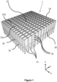
- stackable containers are stacked on top of one another to form stacks 12.
- the stacks 12 are arranged in a frame structure 14 in a warehousing or manufacturing environment.
- Figure 1 is a schematic perspective view of the frame structure 14, and
- Figure 2 is a top-down view showing a single stack 12 of bins 10 arranged within the frame structure 14.
- Each bin 10 typically holds a plurality of product items or good (not shown), and the product items within a bin 10 may be identical, or may be of different product types depending on the application.
- the frame structure 14 comprises a plurality of upright members 16 that support substantially horizontal members 18, 20.
- a first set of substantially parallel substantially horizontal members 18 is arranged perpendicularly to a second set of substantially parallel substantially horizontal members 20 to form a plurality of horizontal grid structures supported by the upright members 16.
- the members 16, 18, 20 are typically manufactured from metal.
- the bins 10 are stacked between the members 16, 18, 20 of the frame structure 14, so that the frame structure 14 guards against horizontal movement of the stacks 12 of bins 10, and guides vertical movement of the bins 10.
- the top level of the frame structure 14 includes rails 22 arranged in a grid pattern across the top of the stacks 12.
- the rails 22 support a plurality of robotic load handling devices 30.
- a first set 22a of parallel rails 22 guide movement of the load handling devices 30 in a first direction (X) across the top of the frame structure 14, and a second set 22b of parallel rails 22, arranged perpendicular to the first set 22a, guide movement of the load handling devices 30 in a second direction (Y), perpendicular to the first direction.
- the rails 22 allow movement of the load handling devices 30 in two dimensions in the X-Y plane, so that a load handling device 30 can be moved into position above any of the stacks 12.
- Each load handling device 30 comprises a vehicle 32 which is arranged to travel in the X and Y directions on the rails 22 of the frame structure 14, above the stacks 12.
- a first set of wheels 34 consisting of a pair of wheels 34 on the front of the vehicle 32 and a pair of wheels 34 on the back of the vehicle 32, are arranged to engage with two adjacent rails of the first set 22a of rails 22.
- a second set of wheels 36 consisting of a pair of wheels 36 on each side of the vehicle 32, are arranged to engage with two adjacent rails of the second set 22b of rails 22.
- Each set of wheels 34, 36 can be lifted and lowered, so that either the first set of wheels 34 or the second set of wheels 36 is engaged with the respective set of rails 22a, 22b at any one time.
- the wheels 34 can be driven, by way of a drive mechanism (not shown) housed in the vehicle 32, to move the load handling device 30 in the X direction.
- a drive mechanism housed in the vehicle 32
- the first set of wheels 34 are lifted clear of the rails 22, and the second set of wheels 36 are lowered into engagement with the second set of rails 22a.
- the drive mechanism can then be used to drive the second set of wheels 36 to achieve movement in the Y direction.
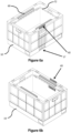
- one or more robotic load handling devices 30 can move around the top surface of the stacks 12 on the frame structure 14 under the control of a central picking system (not shown).
- Each robotic load handling device 30 is provided with means for lifting out one or more bins or containers from the stack 12 to access the required products. In this way, multiple products can be accessed from multiple locations in the grid and stacks at any one time.
- each load handling device can only carry a single container 10 then multiple load handling devices will need to co-operate in order to access the target container 10.
- Figure 4 shows a typical storage system as described above, the system having a plurality of load handling devices 30 active on the stacks 12 in order to co-operate to retrieve and replace containers 10 from and to the stacks 12. Unwanted containers 10 removed from stacks 12 in the pursuit of a target container 10 are placed back in to the stacks 12 at vacant positions.
- Figures 1 and 4 show the bins 10 in stacks 12 within the storage system. It will be appreciated that there may be a large number of bins or containers in any given storage system and that many different goods may be stored within the bins or containers in the stacks 12, each bin or container may contain different goods within a single stack 12 or similar goods may be stored in bins or containers 10 in a given stack or multiple different inventory items or goods may be stored in an individual container 10. Whilst the above described system was conceived to store and retrieve groceries in an online shopping e-commerce solution, it will be appreciated that other uses are envisaged and that other items such as parcels and letters may be stored in the containers 10.
- the bins or containers comprise memory or processing means or the like. It will be appreciated that all of the bins or containers may comprise memory or processing means. Alternatively only a portion of the bins or containers may comprise memory or processing means. It will be appreciated that memory or processing means may comprise computer means or any other means suitable for performing mathematical or computational functions.
- Figures 5a and 5b show one form of suitable container, the container 10, being capable of being held in stacks by co-operating surfaces forming interference fits between adjacent containers 10.
- the container 10 of Figure 5a and 5b additionally comprises connection means 40 at the co-operating surface where containers will cooperate in order to form a stack 12 of containers 10.
- the connection means 40 shown in Figures 5a and 5b comprises a push fit male connector 40 located at the top edge of the container 10.
- the bottom edge of the container comprises a female connector.
- the two containers are linked by routing means that may form part of the container 10 as mouldings or may be pipes, cables, wires or other routing means mounted on the surface of the side of the container 10.
- connector means and routing means is one form only of connector and routing means that may be used, any suitable form of releasable connector means capable of latching or connecting and unlatching or disconnecting as required on movement of the container in or out of the stack 12.
- connection means 40 may comprise electrically conductive layers deposited on the co-operating surfaces of the containers 10 or may comprise sprung-loaded contacts or springs as contacts or any other connection means capable of carrying power, data or other signals between two or more containers 10.
- Noncontacting methods of power transmission may also be used, for example magnetic induction or RF induction and optical methods.
- connection means 40 may comprise carbon loaded rubber contacts capable of carrying signals or data between two or more co-operating containers 10 in a stack.
- containers 10 Whilst the containers may be held in stacks 12 by interference means or by adjacent containers 10 having shaped, co-operating surfaces, containers 10 may be latched together via suitable latching means (not shown).
- the latching means may act to releasably latch two or more containers 10 together in the stack 12.
- the latching means must be capable of remote operation in order that the load handling means may lift individual containers 10 or a plurality of containers 10 latched together. Any form of remotely latching and unlatching means may be used. For example electromagnetic latching means or any other means suitable to perform the function.
- Figures 5a and 5b further show an individual bin 10 comprising power supply means 42 for supplying power to, for example, heating means 56, cooling means 58, data logging means 44, communication means 46 and/or lighting means 60 in Figures 6a and 6b .
- the bin 10 further comprises power control means 43 for controlling the power to the or each service and controlling the power to other containers 10 in the stack 12, if power is to be transmitted to adjacent containers 10 in the stack 12.
- containers 10 comprising power control and control means may power heaters 56, coolers 58, lights 60 or any other service requiring power. Anything requiring power may utilise the power supply means 42.
- the power supply means may comprise batteries or may comprise means for transmitting power from an external power source through connection means 52 on the containers 10 from the base of the storage system or via the uprights 16 of the grid.
- power, data or any other signals may be supplied to the containers 10 in the stacks 12 via power and or data connectors located in the floor of the warehouse. Power may be transmitted up the stacks 12 via the contacts 52 in the co-operating surfaces of the containers 10. Moreover, services may flow up stacks 12 of containers 10 from the floor, for example cooling or heating fluids may be utilised in this manner.
- Figures 5a and 5b further show an individual bin 10 comprising at least data logging means 44 and communication means 46 for transmitting data recorded to a remote central data logging device.
- the data logging means 44 comprises sensors suitable for monitoring the conditions in the bin 10, for example the temperature, any gas emission, for example as a result of decomposing fruit, and humidity.
- the data logging means 44 and communicating means 46 enable the content and condition of individual containers 10 to be monitored.
- knowing information about specific containers 10 in the stacks 12 in the system enables the condition of the storage system as a whole to be monitored.
- the bins or containers 10 per se may be anonymous, a unique identity may be assigned to each bin or container 10 in the storage system. In this way, the location of each bin or container 10 (and by association its contents) may be trackable and identifiable by the system via the communications means. In this way, the topology of the bins or containers 10 can be constructed as a result of each bin or container 10 having knowledge of the identity of the immediately adjacent bins or containers 10 and the bottom bin or container 10 in any stack having knowledge that there are no containers 10 below.
- any type and method of communication may be used, for example WiFi, Bluetooth, 3-wire serial, SigFox or other proprietary systems such as that described in UK Patent Application No. GB1509793.4 to Ocado Innovation Limited, the contents of which in hereby incorporated by reference. It will be appreciated that any other suitable communications means or protocol may be used.
- Figures 5a and 5b further show an individual container 10 from the stack 12, the container 10 comprising heating 56 and/or cooling means 58 and temperature monitoring means 50 for monitoring the temperature in the bin 10.
- the heating means 56 may comprise flow of hot fluid via direct means, for example hot air, or indirect means, for example radiator means or may further comprise electrical heaters or electromagnetic induction heaters.
- the cooling means 58 may comprise Peltier coolers or may comprise flow of cold fluid via direct means, for example cold air or via indirect means, for example radiator means, including ice slurry compressor driven.
- the temperatures of individual containers 10 may be monitored, controlled and varied depending on the content of the individual bin 10. If the contents of the bin need to be chilled or frozen, then the individual bin can have a temperature of 5 degrees C maintained, for chilled, and lower for frozen, rather than requiring a portion of the stacks 12 in the storage system to be maintained at a predetermined temperature by space heaters and coolers.
- the bins or containers 10 may be designed and arranged such that each bin or container 10 is sealed, for example in an airtight fashion, by the bin or container 10 located above.
- the top bin or container 10 in each stack 12 may be provided with a lid, not shown, to seal the top bin or container 10. Sealing the bins or containers 10 in this fashion enables the temperature within an individual bin or container to be more easily controlled by suitable heating or cooling means.
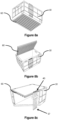
- FIGs 6a and 6b show an alternative form of the bin or container 10 comprising lighting means 60 and fluid supply means 72.
- the same connectors 40 and 17 may be used to route power to the lighting means 60 or water, for example to the fluid supply means 72.
- Figures 7a and 7b show and expanded view of the male connector 40 and the female connector 17 located on or in the side of the bin or container 10.
- Figures 7a and 7b show one example only of the connection means that may form the connections between adjacent bins or containers 10 in a stack 12 of containers 10 in detail.
- Figure 8 shows three examples of an individual bin or container 10 from the stack 12, the bin or container 10 comprising lighting means.
- the lighting means 60 may be provided in the base of a bin to light the bin 10 below.
- the lighting means 60 may comprise a lid 62 containing suitable bulbs, LEDs or any other suitable form of lighting.
- the lid 62 may be removeably attached to the bin 10 and fold away during removal of the bin 10 from the stack 12. Again the power supply to the lighting means 60 is supplied via the connector means 40 and 17 located on the container 10.
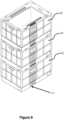
- Figure 9 shows a stack 12 of bins or containers 10 shown in Figure 8 .
- the bins or containers 10 comprise fluid supply means and lighting means 60.
- the connectors 40 and 17 cooperate together to connect each bin or container 10 the bin or container 10 immediately above and below. In this way, services such as power, to power the lighting means 60 or water to irrigate the contents of an individual container 10 may be routed through the containers in the stacks 12.
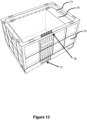
- Figure 10 shows a portion of the framework 14 of the storage system comprising a plurality of bins or containers 10 located therein, the bins or containers 10 carrying services upwardly through the framework 14 of the system by wires, cables or pipes or any other suitable means 17.
- the bottom bin or container 10 in the stack 12 connects to supply means routed through the base of the storage system via connectors 72.
- the supply means in the base may be located in a false base 76 of the system as shown in Figure 10 but may otherwise be routed under the floor of the building comprising the storage system or may be routed via other means.
- Figure 11 shows the connection means between a stack 12 of bins or containers 10 and the supply means in the base 76 of the system in more detail. It will be appreciated that this is one example only of a suitable connection means and that any connector system of releasably connecting bins or containers 10 to power, data, electrical, lighting, telecommunications or any other supply or service may be envisaged.
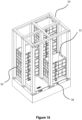
- Figure 12 shows yet another form of individual bin or container 10 in accordance with the invention from a stack 12, the bin or container 10 comprising fluid supply means 72 and further comprising a fluid reservoir 74.
- the contents of the bin or container 10 may require water to be supplied thereto.
- the bin or container 10 is provided with a reservoir 54 that may be filled with a liquid or gas.
- the bin or container 10 may be removed from the stack 12 by the robotic load handling device and taken to a location in the system where the reservoir can be topped up as required.
- the required fluids may be routed to specific containers 10 via the uprights 16 of the grid system.
- Figure 13 shows a further embodiment of the invention in which a bin or container 100 comprises a plurality of smaller bins or containers 110, each of the smaller bins or containers 110 comprising a given service connectable via the connection means 17, 40 located on at least one side of the bin or container 10.
- the storage system described above with reference to the Figures comprises a large number of bins or containers 10 arranged in stacks 12.
- the storage system comprises bins or containers 10 of different categories dispersed within the system.
- bins or containers 10 there may be empty bins or containers 10, bins or containers 10 containing goods to be stored, bins or containers containing services such as power supplies or communications means or data transfer means or data storage means, bins or containers 10 capable of heating, bins or containers 10 capable of cooling, bins or containers 10 comprising goods requiring liquids and/or light.
- some or all of the bins or containers 10 may contain one or more of the services or devices referred to above.
- a bin or container 10 with a reservoir 54 may also be provided with lighting means 60.
- connections between bins or containers 10 and communications between containers 10 and stacks 12 generates a knowledge base of the storage system in real time that will assist in the event of a power outage for example, that will aid in possible disaster recovery.
- the alternative would be to empty all the containers and rebuild the stack which would be inefficient and costly.
- a bin or container 10 comprising temperature sensing means may be used to monitor the temperature in chilled, frozen or ambient sections of the storage system. For example, an increase in the temperature in an ambient portion of the system could result in chocolate melting or ignitables igniting. This may be a particular problem in the summer months in warmer climates.
- a bin or container 10 comprising camera means maybe used to monitor the condition of the grid and other bins or containers 10 in the stacks 12.
- the robotic load handling devices 30 may be used to move the bins or containers 10 around the storage system to inspect portions of the system or other bins or containers 10 or stacks 12 as required. This may be relevant if there have been spillages in the system or other issues with the integrity of the system, grid or bins or containers.
- a bin or container 10 identification means within each individual container 10 together with communications means between bins or containers 10 or stacks 12 may be used to create a topological profile of the storage system, where peer-to-peer identity is possible. In the event of a catastrophic failure of the systems controlling the stacks, the topological information may be used to create a disaster recovery situation.
- Individual bins or containers 10 may be provided with lighting means 60, for use in conjunction with monitoring and camera means in order to assist in inspection of individual bins or containers 10 or the system as a whole. Furthermore, contents of the bins or containers 10 may benefit from lighting of specific wavelengths or a range of wavelengths. For example, under ripe fruit may be brought on using appropriate lighting. Additionally, it may be possible to use bins or containers 10 for cultivation purposes.
- the storage bins or containers 10 may be provided with sensors to detect gas, smoke, fire or heat, the sensors activating sprinkler systems to put out any fire.
- sensors detecting fire or smoke may activate sprinklers and communication means may be provided to directly communicate with a central monitoring system or directly to the emergency services.
- a bin or container 10 comprising gas sensing means may be used to monitor the condition of fruit in a chilled portion of the system. Ripening fruit give off gases so monitoring for these specific gases may provide an indication of over ripening fruit in storage. Should this be detected, containers 10, having cooling means within the bin may be cooled to prevent over ripening of the contents.
- the bins or containers 10 may contain weighing means such as scales to monitor the weight of parcels in storage before onward distribution.
- bins or containers 10 comprising services of some form will require power, data or signal connections to be carried to the services or devices within the bin or container 10.
- electrical connections 40 between bins or containers 10 or between the bottommost bin or container 10 of a stack may be of any suitable form, such as interference connections or any other suitable releasable connector capable of carrying the required power, data or signal between bins or containers 10 or a bin or container 10 and the base of the system or an upright within the system.
- the bins or containers 10 comprise intelligence means such as routers, calculators or servers (not shown).
- the intelligence means may communicate via peer to peer communications across the bins or containers 10 in the system. Furthermore, the communications may occur via contactless light through air communications, however any other suitable means for communication between the containers 10 may be envisaged and used.
- the intelligence means may be powered and controlled by suitable power supply means and power control means such as those means described above.
- Such a system may require extensive cooling.
- Such cooling means may be provided as described above or via cooling means being passed up the uprights 16 of the framework 14 from the base of the system.
- bins or containers 10 may require removal from the stacks 12 for repair reasons, redistribution reasons and to enable the systems or services within a given bin or container 10 to be changed and for many other reasons.
- the load handling device 30 comprising lifting means 39, the lifting means 39 further comprising releasable connecting means 40, the connecting means 40 comprising means for electrically or otherwise connecting the bin or container 10 to a power supply or other service (not shown) located in the load handling device 30.
- the lifting device 39 of the load handling device 30 is provided with cable 80 and connection means 40 suitable for releasably connecting to the bin or container 10.
- the cable 80 performs the function of an umbilical, connecting a power, data or signal source in the load handling device 30 via the releasable connecting means 40 to the container 10.
- Figures 14 and 15 show one form that the connections may take.
- any form of suitable connector 40 may be used capable of carrying power or signals or services as appropriate.
- the cable 80 may be any suitable form of cable capable of carrying the services required.
- the cable 80 may perform multiple functions, for example connecting a power source to the bin or container 10 and carrying data signals to a data storage device carried within the load handling device.
- the load handling device 30 may be utilised a means for downloading data from a bin or container 10 without removing the bin or container 10 from the system.
- FIG 15 is an expanded schematic perspective view of the lifting means of Figure 14 showing in more detail, one form of electrically connecting means 40 for electrically connecting the container to the load handling device 30.
- Figures 16 to 18 demonstrate the use of the make before break connection system.
- Figure 16 shows a portion of the storage system showing a number of stackable bins or containers 10 in situation within the uprights 14 of the storage system, each of the bins or containers 10 being at least electrically connected to the bin or container 10 immediately above and or below as appropriate, the bins or containers 10 at the bottom of each stack 12 being electrically connected to a power source (not shown) located within the storage system, said connections between bins or containers 10 or between bins or containers 10 and the base of the system being releasable when the lifting device 39 of the load handling device 30 is connected.
- the lifting device 39 will connect to the bin or container 10 and establish a connection between the load handling device 30 power source and the bin or container 10 before the bin or container 10 is disconnected from the bin or container 10 to which it is electrically connect beneath.
- connection between the bin or container 10 to be removed and the load handling device 30 will be verified before the bin or container 10 is moved from the stack 12. This verification may be conducted by monitoring load on the load handling device 30 power supply for example or by any other suitable means.
- Figure 17 shows the lifting device 39 being positioned and connected to the top most bin or container 10 of one of the stacks 12 of bins or containers 10 within the storage system, power and/or data and/or signal connections being provided to the load handling device 30 via a daisy-chain like cable 80.
- the cable 80 may take any suitable form and need not be limited to the form of cable 80 shown in the diagrams. It is sufficient for any suitable form of cable 80 to be used capable of carrying the power, data or signals required between the load handling device 30 and the bin or container 10.
- the load handling device 30 is positioned above a bin or container 10 to be removed.
- the lifting device 39 is lowered via suitable motor and tape means 38 down from the load handling device 30.
- the lifting device 39 releasably engages with the target bin or container 10. Once the connection between the bin or container 10 and the load handling device 30 is established, the bin or container 10 is lifted in to the load handling device 30.
- Figure 18 shows a lifting device 39 in accordance with one form of the invention in so far as the services concern power or data, lifting a bin or container 10 from the stack 12 of bins or containers 10, the bin or container 10 being lifted, being electrically connected to the load handling device 30 via a suitable cable 80 as described above.
- each bin or container 10 comprising the intelligence means, calculator or server may be connected with at least its six neighbours via optical channels.
- each calculator could transmit or receive into this channel without disturbing any other traffic, for example, using wavelength division multiplexing.
- each node could have a speed of light, exactly defined latency, connection to every other node in the system.
- such communications means may comprise laser based transmission through air.
- other communication means may be provided, for example connection of the servers or calculators by fibre optic tentacles extending to make contact with neighbours.
- each comprising powerful intelligence means may be combined in to a machine in a stack 60x60 and 28 tall in a 14k sq ft space. Or 1 million containers in a 200x160 grid, 33 tall in a 125k sq ft building.
- bins or containers 10 may be provided with one service, a selection of services or all services described. Furthermore, the services listed should not be regarded as limiting. Any form of service that is capable of being carried or transmitted to a bin or container 10 may be envisaged.
- the storage system comprises bins or containers 10 in stacks 12 disposed within a framework 14 in an unfettered manner.
- the system may be partitioned by suitable partitioning means into smaller sub sections defined by, for example temperature. In this way it would be possible to have an ambient portion, a chilled portion and a frozen portion for example.
- the partitioning may have additional advantages, for example, partitioning enables sections of the storage system to be isolated from other sections. This may be necessary if there is a fire, for example, and fire suppressant means are used in a given area to extinguish the fire.
- partitioning may be temporary and remotely deployable, for example roller shutters disposed under the grid.
- the load handling device 30 carries sufficient power or other resources to maintain the power, data, signal or other services required by the bin or container 10 to be removed from the fixed supplies provided through the framework 14 of the system.
- the load handling device 30 may not have sufficient of the services required.
- the load handling device 30 may be provided with such required services via alternative means.
- These means may include but not be limited to for example an overhead umbilical connected to the load handling device and transported around the system by virtue of the connection to the load handling device capable of carrying the required services to the load handling device for connection to the bin or container 10 to be removed.
- overhead sockets may be provided located above the storage system that the load handling device can releasably attach to such that such services are transmitted via the load handling device 30 to the bin or container 10 to be removed.
- the load handling device 30 may be provided with means for connection to a service being provided via the framework 14 or to an uppermost bin or container 10 in an adjacent stack 12. In this way the required service is provided through the components of the storage system available in close proximity to the load handling device 30 at the pint when a bin or container 10 is to be removed from a stack 12.
- load handling devices 30 operative on the system may form a cluster adjacent the load handling device 30 lifting the target bin or container 10 to then provide required services to the load handling device 30 that is holding the stack 12 of bins or containers 10 requiring the services.
- each load handling device may be configured to connect to, lift and remove one bin or container 10 from a stack 12.
- a load handling device 30 may be configured to connect to, lift and remove more than one bin or container 10 in a single movement.
- bins or containers 10 is used to denote storage containers 10 stackable in stacks 12 within a storage system.
- the storage bins or containers 10 may comprise further containing means within the bin or container 10 structure.
- the containing means may be connected to the bin or container by any suitable means to allow transfer of power, signal or data between the containing means, the bin or container 10 and the load handling device 30. This may be particularly the case should the bin or container be required to carry intelligence or calculating means and require cooling.
Landscapes
- Engineering & Computer Science (AREA)
- Mechanical Engineering (AREA)
- Theoretical Computer Science (AREA)
- Physics & Mathematics (AREA)
- General Engineering & Computer Science (AREA)
- General Physics & Mathematics (AREA)
- Mathematical Physics (AREA)
- Signal Processing (AREA)
- Computer Networks & Wireless Communication (AREA)
- Artificial Intelligence (AREA)
- Computational Linguistics (AREA)
- Data Mining & Analysis (AREA)
- Evolutionary Computation (AREA)
- Computing Systems (AREA)
- Software Systems (AREA)
- Warehouses Or Storage Devices (AREA)
- Preparation Of Compounds By Using Micro-Organisms (AREA)
- Details Of Rigid Or Semi-Rigid Containers (AREA)
- Stackable Containers (AREA)
Priority Applications (2)
| Application Number | Priority Date | Filing Date | Title |
|---|---|---|---|
| PL17790741T PL3529177T4 (pl) | 2016-10-19 | 2017-10-19 | Systemy i sposoby przechowywania |
| HRP20211206TT HRP20211206T4 (hr) | 2016-10-19 | 2017-10-19 | Sustavi i postupci za skladištenje |
Applications Claiming Priority (2)
| Application Number | Priority Date | Filing Date | Title |
|---|---|---|---|
| GBGB1617727.1A GB201617727D0 (en) | 2016-10-19 | 2016-10-19 | Storage systems and methods |
| PCT/EP2017/076799 WO2018073392A1 (en) | 2016-10-19 | 2017-10-19 | Storage systems and methods |
Publications (3)
| Publication Number | Publication Date |
|---|---|
| EP3529177A1 EP3529177A1 (en) | 2019-08-28 |
| EP3529177B1 EP3529177B1 (en) | 2021-04-28 |
| EP3529177B2 true EP3529177B2 (en) | 2024-02-07 |
Family
ID=57680859
Family Applications (1)
| Application Number | Title | Priority Date | Filing Date |
|---|---|---|---|
| EP17790741.7A Active EP3529177B2 (en) | 2016-10-19 | 2017-10-19 | Storage systems and methods |
Country Status (15)
| Country | Link |
|---|---|
| US (3) | US10919699B2 (ko) |
| EP (1) | EP3529177B2 (ko) |
| JP (3) | JP6953524B2 (ko) |
| KR (3) | KR102585087B1 (ko) |
| CN (3) | CN113548358A (ko) |
| AU (2) | AU2017347684B2 (ko) |
| CA (1) | CA3041170A1 (ko) |
| ES (1) | ES2882176T3 (ko) |
| FI (1) | FI3529177T4 (ko) |
| GB (2) | GB201617727D0 (ko) |
| HR (1) | HRP20211206T4 (ko) |
| HU (1) | HUE054956T2 (ko) |
| PL (1) | PL3529177T4 (ko) |
| PT (1) | PT3529177T (ko) |
| WO (1) | WO2018073392A1 (ko) |
Families Citing this family (28)
| Publication number | Priority date | Publication date | Assignee | Title |
|---|---|---|---|---|
| GB201509921D0 (en) * | 2015-06-08 | 2015-07-22 | Ocado Innovation Ltd | Object storage, handling and retrieving system and method |
| GB201617727D0 (en) * | 2016-10-19 | 2016-11-30 | Ocado Innovation Limited | Storage systems and methods |
| CN111727159B (zh) | 2018-01-09 | 2022-04-22 | 自动存储科技股份有限公司 | 用于遥控式运载工具的移位机构 |
| NO345674B1 (en) * | 2018-04-25 | 2021-06-07 | Autostore Tech As | Container-handling vehicle with a lifting shaft and method of operating gripper elements on a lifting frame of a container-handling vehicle |
| GB2570119B (en) * | 2018-01-10 | 2022-06-08 | Ocado Innovation Ltd | A controller and method for transporting devices |
| GB201805917D0 (en) * | 2018-04-10 | 2018-05-23 | Ocado Innovation Ltd | System and method for picking items |
| GB201807562D0 (en) * | 2018-05-09 | 2018-06-20 | Ocado Innovation Ltd | Apparatus and method for charging a robotic load handling device |
| NO20181419A1 (en) * | 2018-11-06 | 2020-05-07 | Autostore Tech As | Container handling vehicle with an open top, and method of handling product items into storage container carried by the vehicle |
| US11361277B2 (en) * | 2019-03-06 | 2022-06-14 | Walmart Apollo, Llc | Integrated container conveyance system |
| CN111022029B (zh) * | 2019-11-11 | 2022-10-28 | 东华理工大学 | 一种测井放射源自动安装更换装置 |
| GB202001012D0 (en) * | 2020-01-24 | 2020-03-11 | Ocado Innovation Ltd | Raising and lowering containers |
| GB202001297D0 (en) * | 2020-01-30 | 2020-03-18 | Ocado Innovation Ltd | Apparatus and method for charging a load handling device |
| NO345920B1 (en) * | 2020-01-31 | 2021-10-25 | Autostore Tech As | A system and method for monitoring atmospheric conditions in an automated storage and retrieval system |
| NO345896B1 (en) * | 2020-01-31 | 2021-10-04 | Autostore Tech As | System and method for performing measurements while containers are being handled by container handling vehicles |
| GB202005636D0 (en) * | 2020-04-17 | 2020-06-03 | Ocado Innovation Ltd | Multitemprature storage system |
| EP3906777A1 (de) * | 2020-05-04 | 2021-11-10 | Jungheinrich Aktiengesellschaft | Gewächshausanordnung |
| JP7035113B2 (ja) * | 2020-06-03 | 2022-03-14 | ソフトバンク株式会社 | システム、搭載装置、管理装置、プログラム、及び管理方法 |
| NO20200756A1 (en) * | 2020-06-26 | 2021-12-27 | Autostore Tech As | Automated storage and retrieval system and method for storing fresh food and produce |
| CN113184431B (zh) * | 2021-04-28 | 2023-04-18 | 立臻科技(昆山)有限公司 | 一种智能物料柜以及物料存取方法 |
| NO346764B1 (en) | 2021-06-10 | 2022-12-19 | Autostore Tech As | A storage container for an automated, grid-based storage and retrieval system. |
| CN113895757B (zh) * | 2021-09-24 | 2023-04-11 | 杭州首展科技有限公司 | 一种供应链分发跟进装置以及方法 |
| GB202300771D0 (en) * | 2022-01-31 | 2023-03-08 | Dematic Corp | Automated storage and retrieval system and microclimate-controlled receptacles for pharmaceuticals and method for operating same |
| GB2616945A (en) * | 2022-01-31 | 2023-09-27 | Dematic Corp | Automated storage and retrieval system with microclimate-controlled receptacles |
| EP4238898A1 (de) * | 2022-03-03 | 2023-09-06 | Jungheinrich Aktiengesellschaft | Blocklageranordnung |
| GB2618385A (en) * | 2022-05-06 | 2023-11-08 | Ocado Innovation Ltd | Storage containers for a grid framework structure |
| WO2023227532A1 (en) * | 2022-05-23 | 2023-11-30 | Ocado Innovation Limited | Multi-temperature storage system |
| CN114987897A (zh) * | 2022-05-23 | 2022-09-02 | 上海发电设备成套设计研究院有限责任公司 | 一种核电设备辐照老化试验的保温装置及其用途 |
| GB2619064A (en) * | 2022-05-26 | 2023-11-29 | Ocado Innovation Ltd | A combined power and data unit for a storage and retreival system, and related devices |
Family Cites Families (46)
| Publication number | Priority date | Publication date | Assignee | Title |
|---|---|---|---|---|
| US2701065A (en) | 1950-09-06 | 1955-02-01 | Charles A Bertel | Apparatus for storing and handling containers |
| JPS63258389A (ja) * | 1987-04-14 | 1988-10-25 | 株式会社ダイフク | 吊り下げ昇降装置付き搬送台車 |
| US5473908A (en) | 1987-11-12 | 1995-12-12 | The Pallet Reefer Company | Portable self-contained cooler/freezer apparatus for use on airplanes, common carrier type unrefrigerated truck lines, and vessels |
| JPH02150221A (ja) | 1988-01-29 | 1990-06-08 | Tamnaharry Dev Ltd | ひな鳥収容器の繰出し及び積重ね装置並びに繰出し及び積重ね方法 |
| JPH0558587A (ja) * | 1991-08-30 | 1993-03-09 | Daifuku Co Ltd | 吊下昇降移載装置付き搬送装置 |
| JP2570638Y2 (ja) * | 1992-07-17 | 1998-05-06 | 石川島播磨重工業株式会社 | 天井走行台車の把持装置への給電装置 |
| FI105668B (fi) | 1995-10-02 | 2000-09-29 | Cimcorp Oy | Poimintajärjestelmä |
| US5602721A (en) | 1995-12-22 | 1997-02-11 | Tandem Computers | Expandable modular computer system |
| NO972004D0 (no) | 1997-04-30 | 1997-04-30 | Hatteland Electronic As Jacob | Metode for organisering av vareflyt for en horisontalt lagdelt og dypstablet lagerbeholdning med uensartede komponenter, samt forflytningsutstyr for standariserte beholdere til formålet |
| NO317366B1 (no) | 1999-07-01 | 2004-10-18 | Autostore As | Lagringsanlegg med fjernstyrte vogner med to hjulsett og heisinnretning for drift på skinner anlagt i kryss over kolonner av lagringsenheter som er adskilt med vertikale profilstolper |
| US20030156501A1 (en) * | 2002-01-14 | 2003-08-21 | Martin Spindel | Trackable storage unit system and method |
| JP2004323169A (ja) | 2003-04-24 | 2004-11-18 | Food Safety Innovation Gijutsu Kenkyu Kumiai | 物流管理システム |
| US8651790B2 (en) * | 2006-09-25 | 2014-02-18 | Charles E. Benedict | Warehouse storage system |
| SE0402030L (sv) * | 2004-08-16 | 2006-02-17 | Moving Ab | System och förfarande för lagerhantering |
| WO2006071227A1 (en) | 2004-12-28 | 2006-07-06 | Great American Lines, Inc. | Container inspection system |
| DE102008019964B4 (de) | 2008-04-21 | 2013-02-28 | Deutsche Post Ag | Mobiler Frachtbehälter mit induktiver Energieversorgung; Umschlag- und/oder Transporteinrichtung für Frachtbehälter; Behälterlogistiksystem und Verfahren zur Energieversorgung eines Frachtbehälters |
| JP2012056659A (ja) * | 2010-09-07 | 2012-03-22 | Murata Machinery Ltd | 自動倉庫とその容器 |
| CN103329063B (zh) * | 2010-10-04 | 2017-09-12 | 阿沃森特亨茨维尔有限责任公司 | 用于实时地监视和管理数据中心资源的系统和方法 |
| CN103348328B (zh) * | 2010-10-04 | 2016-09-14 | 阿沃森特亨茨维尔公司 | 用于实时地监视并管理数据中心资源的系统和方法 |
| WO2013027761A1 (ja) | 2011-08-22 | 2013-02-28 | 積水化学工業株式会社 | リーファーコンテナ及びリーファーコンテナへの給電システム |
| WO2013082601A1 (en) * | 2011-12-03 | 2013-06-06 | Scott Dittman | Photosynthetic grow module and methods of use |
| DE102011089858A1 (de) * | 2011-12-23 | 2013-06-27 | Krones Ag | System zum Transport von auf Hilfsmitteln angeordneten Gütern |
| EP2847105B1 (en) * | 2012-05-11 | 2021-06-23 | Ocado Innovation Limited | Storage systems and methods for retrieving units from a storage system |
| US8963716B2 (en) | 2013-01-08 | 2015-02-24 | Imicrodata Corporation | Storage container for electronically addressable file folders and documents |
| JP6133070B2 (ja) * | 2013-02-04 | 2017-05-24 | 株式会社椿本チエイン | 低温保管システム |
| US9558454B2 (en) * | 2013-03-14 | 2017-01-31 | Futurewei Technologies, Inc. | System and method for model-based inventory management of a communications system |
| GB201310125D0 (en) * | 2013-06-06 | 2013-07-24 | Ocado Ltd | Storage and retrieval system |
| GB201310784D0 (en) | 2013-06-17 | 2013-07-31 | Ocado Ltd | Systems and Methods for Order Processing |
| GB201314313D0 (en) * | 2013-08-09 | 2013-09-25 | Ocado Ltd | Apparatus for retrieving units from a storage system |
| ITTO20131102A1 (it) * | 2013-12-31 | 2015-07-01 | Bonetto S R L | Sistema automatizzato o semiautomatizzato di stoccaggio e prelievo a temperature differenziate |
| NO340313B1 (no) * | 2014-01-08 | 2017-03-27 | Jakob Hatteland Logistics As | Fjernstyrt kjøretøy for å plukke opp lagringsbeholdere fra et lagringssystem, lagringssystem for lagring av beholdere og fremgangsmåte for å bytte en strømkilde |
| NL2012078C2 (en) | 2014-01-13 | 2015-07-16 | Kees Wilhelmus Petrus Aarts | Crate, control unit for a crate, stack of crates and method for operating these. |
| GB2527543A (en) * | 2014-06-25 | 2015-12-30 | Ocado Innovation Ltd | System and method for managing shipping containers |
| CN114162509A (zh) | 2015-04-15 | 2022-03-11 | 奥卡多创新有限公司 | 物品处理系统与方法 |
| EP3282830B1 (en) | 2015-04-15 | 2023-12-27 | Ocado Innovation Limited | Growing system |
| WO2016166323A1 (en) | 2015-04-15 | 2016-10-20 | Ocado Innovation Limited | Storage system with partition means and methods |
| KR20240024346A (ko) | 2015-04-15 | 2024-02-23 | 오카도 이노베이션 리미티드 | 보관 시스템 및 방법 |
| GB2541766A (en) | 2015-04-15 | 2017-03-01 | Ocado Innovation Ltd | Storage systems and methods |
| WO2016166353A1 (en) * | 2015-04-15 | 2016-10-20 | Ocado Innovation Limited | Storage system and methods |
| GB201602332D0 (en) | 2015-04-15 | 2016-03-23 | Ocado Innovation Ltd | Robotic container handling device and method |
| GB2541488A (en) | 2015-04-15 | 2017-02-22 | Ocado Innovation Ltd | Robotic picking system device and method |
| KR20230043230A (ko) | 2015-04-15 | 2023-03-30 | 오카도 이노베이션 리미티드 | 로봇 주차 장치 및 핸들링 방법 |
| GB2541764B (en) | 2015-04-15 | 2018-04-11 | Ocado Innovation Ltd | System and method for configuration of buildings or storage |
| CN105460475B (zh) * | 2015-11-18 | 2018-05-11 | 国家电网公司 | 一种插件智能储存装置 |
| NO342469B1 (en) | 2016-02-01 | 2018-05-28 | Autostore Tech As | Cleaning bin for cleaning a storage grid of a storage system and method for the same |
| GB201617727D0 (en) * | 2016-10-19 | 2016-11-30 | Ocado Innovation Limited | Storage systems and methods |
-
2016
- 2016-10-19 GB GBGB1617727.1A patent/GB201617727D0/en not_active Ceased
-
2017
- 2017-10-19 ES ES17790741T patent/ES2882176T3/es active Active
- 2017-10-19 HU HUE17790741A patent/HUE054956T2/hu unknown
- 2017-10-19 KR KR1020227036863A patent/KR102585087B1/ko active IP Right Grant
- 2017-10-19 US US16/343,124 patent/US10919699B2/en active Active
- 2017-10-19 EP EP17790741.7A patent/EP3529177B2/en active Active
- 2017-10-19 PL PL17790741T patent/PL3529177T4/pl unknown
- 2017-10-19 CN CN202110896575.6A patent/CN113548358A/zh active Pending
- 2017-10-19 FI FIEP17790741.7T patent/FI3529177T4/fi active
- 2017-10-19 CN CN201780069603.9A patent/CN109923048B/zh active Active
- 2017-10-19 CN CN202110967054.5A patent/CN113734679A/zh active Pending
- 2017-10-19 KR KR1020197013853A patent/KR102362845B1/ko active IP Right Grant
- 2017-10-19 CA CA3041170A patent/CA3041170A1/en active Pending
- 2017-10-19 KR KR1020227004447A patent/KR102459447B1/ko active IP Right Grant
- 2017-10-19 HR HRP20211206TT patent/HRP20211206T4/hr unknown
- 2017-10-19 GB GB1717214.9A patent/GB2558052B/en active Active
- 2017-10-19 AU AU2017347684A patent/AU2017347684B2/en active Active
- 2017-10-19 WO PCT/EP2017/076799 patent/WO2018073392A1/en unknown
- 2017-10-19 JP JP2019520953A patent/JP6953524B2/ja active Active
- 2017-10-19 PT PT177907417T patent/PT3529177T/pt unknown
-
2021
- 2021-02-11 US US17/174,020 patent/US11554914B2/en active Active
- 2021-09-29 JP JP2021158914A patent/JP7203924B2/ja active Active
-
2022
- 2022-12-09 US US18/063,856 patent/US20230108952A1/en active Pending
- 2022-12-27 JP JP2022210088A patent/JP7413499B2/ja active Active
-
2023
- 2023-06-16 AU AU2023203787A patent/AU2023203787A1/en active Pending
Also Published As
Similar Documents
| Publication | Publication Date | Title |
|---|---|---|
| US11554914B2 (en) | Storage systems and methods | |
| US11299344B2 (en) | Storage systems and methods | |
| JP6968918B2 (ja) | 貯蔵システムおよび方法 |
Legal Events
| Date | Code | Title | Description |
|---|---|---|---|
| STAA | Information on the status of an ep patent application or granted ep patent |
Free format text: STATUS: UNKNOWN |
|
| STAA | Information on the status of an ep patent application or granted ep patent |
Free format text: STATUS: THE INTERNATIONAL PUBLICATION HAS BEEN MADE |
|
| PUAI | Public reference made under article 153(3) epc to a published international application that has entered the european phase |
Free format text: ORIGINAL CODE: 0009012 |
|
| STAA | Information on the status of an ep patent application or granted ep patent |
Free format text: STATUS: REQUEST FOR EXAMINATION WAS MADE |
|
| 17P | Request for examination filed |
Effective date: 20190515 |
|
| AK | Designated contracting states |
Kind code of ref document: A1 Designated state(s): AL AT BE BG CH CY CZ DE DK EE ES FI FR GB GR HR HU IE IS IT LI LT LU LV MC MK MT NL NO PL PT RO RS SE SI SK SM TR |
|
| AX | Request for extension of the european patent |
Extension state: BA ME |
|
| DAV | Request for validation of the european patent (deleted) | ||
| DAX | Request for extension of the european patent (deleted) | ||
| GRAP | Despatch of communication of intention to grant a patent |
Free format text: ORIGINAL CODE: EPIDOSNIGR1 |
|
| STAA | Information on the status of an ep patent application or granted ep patent |
Free format text: STATUS: GRANT OF PATENT IS INTENDED |
|
| INTG | Intention to grant announced |
Effective date: 20201119 |
|
| GRAS | Grant fee paid |
Free format text: ORIGINAL CODE: EPIDOSNIGR3 |
|
| GRAA | (expected) grant |
Free format text: ORIGINAL CODE: 0009210 |
|
| STAA | Information on the status of an ep patent application or granted ep patent |
Free format text: STATUS: THE PATENT HAS BEEN GRANTED |
|
| AK | Designated contracting states |
Kind code of ref document: B1 Designated state(s): AL AT BE BG CH CY CZ DE DK EE ES FI FR GB GR HR HU IE IS IT LI LT LU LV MC MK MT NL NO PL PT RO RS SE SI SK SM TR |
|
| REG | Reference to a national code |
Ref country code: GB Ref legal event code: FG4D |
|
| REG | Reference to a national code |
Ref country code: CH Ref legal event code: EP |
|
| REG | Reference to a national code |
Ref country code: AT Ref legal event code: REF Ref document number: 1386847 Country of ref document: AT Kind code of ref document: T Effective date: 20210515 |
|
| REG | Reference to a national code |
Ref country code: DE Ref legal event code: R096 Ref document number: 602017037707 Country of ref document: DE |
|
| REG | Reference to a national code |
Ref country code: IE Ref legal event code: FG4D |
|
| REG | Reference to a national code |
Ref country code: RO Ref legal event code: EPE Ref country code: HR Ref legal event code: TUEP Ref document number: P20211206T Country of ref document: HR |
|
| REG | Reference to a national code |
Ref country code: FI Ref legal event code: FGE |
|
| REG | Reference to a national code |
Ref country code: PT Ref legal event code: SC4A Ref document number: 3529177 Country of ref document: PT Date of ref document: 20210802 Kind code of ref document: T Free format text: AVAILABILITY OF NATIONAL TRANSLATION Effective date: 20210727 |
|
| REG | Reference to a national code |
Ref country code: NL Ref legal event code: FP |
|
| REG | Reference to a national code |
Ref country code: SE Ref legal event code: TRGR |
|
| REG | Reference to a national code |
Ref country code: LT Ref legal event code: MG9D |
|
| REG | Reference to a national code |
Ref country code: NO Ref legal event code: T2 Effective date: 20210428 |
|
| REG | Reference to a national code |
Ref country code: HR Ref legal event code: ODRP Ref document number: P20211206T Country of ref document: HR Payment date: 20211012 Year of fee payment: 5 |
|
| REG | Reference to a national code |
Ref country code: HU Ref legal event code: AG4A Ref document number: E054956 Country of ref document: HU |
|
| PG25 | Lapsed in a contracting state [announced via postgrant information from national office to epo] |
Ref country code: LT Free format text: LAPSE BECAUSE OF FAILURE TO SUBMIT A TRANSLATION OF THE DESCRIPTION OR TO PAY THE FEE WITHIN THE PRESCRIBED TIME-LIMIT Effective date: 20210428 |
|
| REG | Reference to a national code |
Ref country code: HR Ref legal event code: T1PR Ref document number: P20211206 Country of ref document: HR |
|
| PG25 | Lapsed in a contracting state [announced via postgrant information from national office to epo] |
Ref country code: IS Free format text: LAPSE BECAUSE OF FAILURE TO SUBMIT A TRANSLATION OF THE DESCRIPTION OR TO PAY THE FEE WITHIN THE PRESCRIBED TIME-LIMIT Effective date: 20210828 Ref country code: GR Free format text: LAPSE BECAUSE OF FAILURE TO SUBMIT A TRANSLATION OF THE DESCRIPTION OR TO PAY THE FEE WITHIN THE PRESCRIBED TIME-LIMIT Effective date: 20210729 Ref country code: LV Free format text: LAPSE BECAUSE OF FAILURE TO SUBMIT A TRANSLATION OF THE DESCRIPTION OR TO PAY THE FEE WITHIN THE PRESCRIBED TIME-LIMIT Effective date: 20210428 Ref country code: RS Free format text: LAPSE BECAUSE OF FAILURE TO SUBMIT A TRANSLATION OF THE DESCRIPTION OR TO PAY THE FEE WITHIN THE PRESCRIBED TIME-LIMIT Effective date: 20210428 |
|
| REG | Reference to a national code |
Ref country code: ES Ref legal event code: FG2A Ref document number: 2882176 Country of ref document: ES Kind code of ref document: T3 Effective date: 20211201 |
|
| REG | Reference to a national code |
Ref country code: DE Ref legal event code: R026 Ref document number: 602017037707 Country of ref document: DE |
|
| PG25 | Lapsed in a contracting state [announced via postgrant information from national office to epo] |
Ref country code: DK Free format text: LAPSE BECAUSE OF FAILURE TO SUBMIT A TRANSLATION OF THE DESCRIPTION OR TO PAY THE FEE WITHIN THE PRESCRIBED TIME-LIMIT Effective date: 20210428 Ref country code: EE Free format text: LAPSE BECAUSE OF FAILURE TO SUBMIT A TRANSLATION OF THE DESCRIPTION OR TO PAY THE FEE WITHIN THE PRESCRIBED TIME-LIMIT Effective date: 20210428 Ref country code: SM Free format text: LAPSE BECAUSE OF FAILURE TO SUBMIT A TRANSLATION OF THE DESCRIPTION OR TO PAY THE FEE WITHIN THE PRESCRIBED TIME-LIMIT Effective date: 20210428 Ref country code: SK Free format text: LAPSE BECAUSE OF FAILURE TO SUBMIT A TRANSLATION OF THE DESCRIPTION OR TO PAY THE FEE WITHIN THE PRESCRIBED TIME-LIMIT Effective date: 20210428 |
|
| PLBI | Opposition filed |
Free format text: ORIGINAL CODE: 0009260 |
|
| PLAX | Notice of opposition and request to file observation + time limit sent |
Free format text: ORIGINAL CODE: EPIDOSNOBS2 |
|
| REG | Reference to a national code |
Ref country code: FI Ref legal event code: MDE Opponent name: AUTOSTORE TECHNOLOGY AS |
|
| 26 | Opposition filed |
Opponent name: AUTOSTORE TECHNOLOGY AS Effective date: 20220128 |
|
| PG25 | Lapsed in a contracting state [announced via postgrant information from national office to epo] |
Ref country code: IS Free format text: LAPSE BECAUSE OF FAILURE TO SUBMIT A TRANSLATION OF THE DESCRIPTION OR TO PAY THE FEE WITHIN THE PRESCRIBED TIME-LIMIT Effective date: 20210828 Ref country code: AL Free format text: LAPSE BECAUSE OF FAILURE TO SUBMIT A TRANSLATION OF THE DESCRIPTION OR TO PAY THE FEE WITHIN THE PRESCRIBED TIME-LIMIT Effective date: 20210428 |
|
| PLBB | Reply of patent proprietor to notice(s) of opposition received |
Free format text: ORIGINAL CODE: EPIDOSNOBS3 |
|
| PG25 | Lapsed in a contracting state [announced via postgrant information from national office to epo] |
Ref country code: MC Free format text: LAPSE BECAUSE OF FAILURE TO SUBMIT A TRANSLATION OF THE DESCRIPTION OR TO PAY THE FEE WITHIN THE PRESCRIBED TIME-LIMIT Effective date: 20210428 |
|
| REG | Reference to a national code |
Ref country code: AT Ref legal event code: UEP Ref document number: 1386847 Country of ref document: AT Kind code of ref document: T Effective date: 20210428 |
|
| REG | Reference to a national code |
Ref country code: HR Ref legal event code: ODRP Ref document number: P20211206 Country of ref document: HR Payment date: 20221012 Year of fee payment: 6 |
|
| P01 | Opt-out of the competence of the unified patent court (upc) registered |
Effective date: 20230505 |
|
| PG25 | Lapsed in a contracting state [announced via postgrant information from national office to epo] |
Ref country code: CY Free format text: LAPSE BECAUSE OF FAILURE TO SUBMIT A TRANSLATION OF THE DESCRIPTION OR TO PAY THE FEE WITHIN THE PRESCRIBED TIME-LIMIT Effective date: 20210428 |
|
| PLBP | Opposition withdrawn |
Free format text: ORIGINAL CODE: 0009264 |
|
| REG | Reference to a national code |
Ref country code: HR Ref legal event code: ODRP Ref document number: P20211206 Country of ref document: HR Payment date: 20231005 Year of fee payment: 7 |
|
| PGFP | Annual fee paid to national office [announced via postgrant information from national office to epo] |
Ref country code: NL Payment date: 20231019 Year of fee payment: 7 |
|
| PGFP | Annual fee paid to national office [announced via postgrant information from national office to epo] |
Ref country code: LU Payment date: 20231019 Year of fee payment: 7 |
|
| PUAH | Patent maintained in amended form |
Free format text: ORIGINAL CODE: 0009272 |
|
| STAA | Information on the status of an ep patent application or granted ep patent |
Free format text: STATUS: PATENT MAINTAINED AS AMENDED |
|
| PGFP | Annual fee paid to national office [announced via postgrant information from national office to epo] |
Ref country code: GB Payment date: 20231020 Year of fee payment: 7 |
|
| PGFP | Annual fee paid to national office [announced via postgrant information from national office to epo] |
Ref country code: ES Payment date: 20231227 Year of fee payment: 7 |
|
| PGFP | Annual fee paid to national office [announced via postgrant information from national office to epo] |
Ref country code: SE Payment date: 20231019 Year of fee payment: 7 Ref country code: RO Payment date: 20231005 Year of fee payment: 7 Ref country code: PT Payment date: 20231006 Year of fee payment: 7 Ref country code: NO Payment date: 20231025 Year of fee payment: 7 Ref country code: IT Payment date: 20231023 Year of fee payment: 7 Ref country code: IE Payment date: 20231023 Year of fee payment: 7 Ref country code: HU Payment date: 20231024 Year of fee payment: 7 Ref country code: HR Payment date: 20231005 Year of fee payment: 7 Ref country code: FR Payment date: 20231026 Year of fee payment: 7 Ref country code: FI Payment date: 20231020 Year of fee payment: 7 Ref country code: DE Payment date: 20231020 Year of fee payment: 7 Ref country code: CZ Payment date: 20231006 Year of fee payment: 7 Ref country code: CH Payment date: 20231102 Year of fee payment: 7 Ref country code: BG Payment date: 20231020 Year of fee payment: 7 Ref country code: AT Payment date: 20231020 Year of fee payment: 7 |
|
| 27A | Patent maintained in amended form |
Effective date: 20240207 |
|
| AK | Designated contracting states |
Kind code of ref document: B2 Designated state(s): AL AT BE BG CH CY CZ DE DK EE ES FI FR GB GR HR HU IE IS IT LI LT LU LV MC MK MT NL NO PL PT RO RS SE SI SK SM TR |
|
| REG | Reference to a national code |
Ref country code: DE Ref legal event code: R102 Ref document number: 602017037707 Country of ref document: DE |
|
| PGFP | Annual fee paid to national office [announced via postgrant information from national office to epo] |
Ref country code: PL Payment date: 20231006 Year of fee payment: 7 Ref country code: BE Payment date: 20231019 Year of fee payment: 7 |
|
| REG | Reference to a national code |
Ref country code: SE Ref legal event code: RPEO |
|
| REG | Reference to a national code |
Ref country code: HR Ref legal event code: T4IZ Ref document number: P20211206 Country of ref document: HR |
|
| PG25 | Lapsed in a contracting state [announced via postgrant information from national office to epo] |
Ref country code: MK Free format text: LAPSE BECAUSE OF FAILURE TO SUBMIT A TRANSLATION OF THE DESCRIPTION OR TO PAY THE FEE WITHIN THE PRESCRIBED TIME-LIMIT Effective date: 20210428 |
|
| REG | Reference to a national code |
Ref country code: AT Ref legal event code: UEP Ref document number: 1386847 Country of ref document: AT Kind code of ref document: T Effective date: 20240207 |