EP3529114B1 - Magnetventil zur steuerung des bremsdrucks einer radbremse und werkzeug zur herstellung seines ventilelements - Google Patents
Magnetventil zur steuerung des bremsdrucks einer radbremse und werkzeug zur herstellung seines ventilelements Download PDFInfo
- Publication number
- EP3529114B1 EP3529114B1 EP17769098.9A EP17769098A EP3529114B1 EP 3529114 B1 EP3529114 B1 EP 3529114B1 EP 17769098 A EP17769098 A EP 17769098A EP 3529114 B1 EP3529114 B1 EP 3529114B1
- Authority
- EP
- European Patent Office
- Prior art keywords
- valve
- armature
- valve element
- producing
- solenoid valve
- Prior art date
- Legal status (The legal status is an assumption and is not a legal conclusion. Google has not performed a legal analysis and makes no representation as to the accuracy of the status listed.)
- Active
Links
Images

Classifications
-
- B—PERFORMING OPERATIONS; TRANSPORTING
- B60—VEHICLES IN GENERAL
- B60T—VEHICLE BRAKE CONTROL SYSTEMS OR PARTS THEREOF; BRAKE CONTROL SYSTEMS OR PARTS THEREOF, IN GENERAL; ARRANGEMENT OF BRAKING ELEMENTS ON VEHICLES IN GENERAL; PORTABLE DEVICES FOR PREVENTING UNWANTED MOVEMENT OF VEHICLES; VEHICLE MODIFICATIONS TO FACILITATE COOLING OF BRAKES
- B60T8/00—Arrangements for adjusting wheel-braking force to meet varying vehicular or ground-surface conditions, e.g. limiting or varying distribution of braking force
- B60T8/32—Arrangements for adjusting wheel-braking force to meet varying vehicular or ground-surface conditions, e.g. limiting or varying distribution of braking force responsive to a speed condition, e.g. acceleration or deceleration
- B60T8/34—Arrangements for adjusting wheel-braking force to meet varying vehicular or ground-surface conditions, e.g. limiting or varying distribution of braking force responsive to a speed condition, e.g. acceleration or deceleration having a fluid pressure regulator responsive to a speed condition
- B60T8/36—Arrangements for adjusting wheel-braking force to meet varying vehicular or ground-surface conditions, e.g. limiting or varying distribution of braking force responsive to a speed condition, e.g. acceleration or deceleration having a fluid pressure regulator responsive to a speed condition including a pilot valve responding to an electromagnetic force
- B60T8/3615—Electromagnetic valves specially adapted for anti-lock brake and traction control systems
- B60T8/363—Electromagnetic valves specially adapted for anti-lock brake and traction control systems in hydraulic systems
-
- B—PERFORMING OPERATIONS; TRANSPORTING
- B60—VEHICLES IN GENERAL
- B60T—VEHICLE BRAKE CONTROL SYSTEMS OR PARTS THEREOF; BRAKE CONTROL SYSTEMS OR PARTS THEREOF, IN GENERAL; ARRANGEMENT OF BRAKING ELEMENTS ON VEHICLES IN GENERAL; PORTABLE DEVICES FOR PREVENTING UNWANTED MOVEMENT OF VEHICLES; VEHICLE MODIFICATIONS TO FACILITATE COOLING OF BRAKES
- B60T13/00—Transmitting braking action from initiating means to ultimate brake actuator with power assistance or drive; Brake systems incorporating such transmitting means, e.g. air-pressure brake systems
- B60T13/10—Transmitting braking action from initiating means to ultimate brake actuator with power assistance or drive; Brake systems incorporating such transmitting means, e.g. air-pressure brake systems with fluid assistance, drive, or release
- B60T13/66—Electrical control in fluid-pressure brake systems
- B60T13/68—Electrical control in fluid-pressure brake systems by electrically-controlled valves
- B60T13/686—Electrical control in fluid-pressure brake systems by electrically-controlled valves in hydraulic systems or parts thereof
-
- B—PERFORMING OPERATIONS; TRANSPORTING
- B60—VEHICLES IN GENERAL
- B60T—VEHICLE BRAKE CONTROL SYSTEMS OR PARTS THEREOF; BRAKE CONTROL SYSTEMS OR PARTS THEREOF, IN GENERAL; ARRANGEMENT OF BRAKING ELEMENTS ON VEHICLES IN GENERAL; PORTABLE DEVICES FOR PREVENTING UNWANTED MOVEMENT OF VEHICLES; VEHICLE MODIFICATIONS TO FACILITATE COOLING OF BRAKES
- B60T8/00—Arrangements for adjusting wheel-braking force to meet varying vehicular or ground-surface conditions, e.g. limiting or varying distribution of braking force
- B60T8/32—Arrangements for adjusting wheel-braking force to meet varying vehicular or ground-surface conditions, e.g. limiting or varying distribution of braking force responsive to a speed condition, e.g. acceleration or deceleration
- B60T8/34—Arrangements for adjusting wheel-braking force to meet varying vehicular or ground-surface conditions, e.g. limiting or varying distribution of braking force responsive to a speed condition, e.g. acceleration or deceleration having a fluid pressure regulator responsive to a speed condition
- B60T8/36—Arrangements for adjusting wheel-braking force to meet varying vehicular or ground-surface conditions, e.g. limiting or varying distribution of braking force responsive to a speed condition, e.g. acceleration or deceleration having a fluid pressure regulator responsive to a speed condition including a pilot valve responding to an electromagnetic force
-
- F—MECHANICAL ENGINEERING; LIGHTING; HEATING; WEAPONS; BLASTING
- F16—ENGINEERING ELEMENTS AND UNITS; GENERAL MEASURES FOR PRODUCING AND MAINTAINING EFFECTIVE FUNCTIONING OF MACHINES OR INSTALLATIONS; THERMAL INSULATION IN GENERAL
- F16K—VALVES; TAPS; COCKS; ACTUATING-FLOATS; DEVICES FOR VENTING OR AERATING
- F16K27/00—Construction of housing; Use of materials therefor
-
- F—MECHANICAL ENGINEERING; LIGHTING; HEATING; WEAPONS; BLASTING
- F16—ENGINEERING ELEMENTS AND UNITS; GENERAL MEASURES FOR PRODUCING AND MAINTAINING EFFECTIVE FUNCTIONING OF MACHINES OR INSTALLATIONS; THERMAL INSULATION IN GENERAL
- F16K—VALVES; TAPS; COCKS; ACTUATING-FLOATS; DEVICES FOR VENTING OR AERATING
- F16K31/00—Actuating devices; Operating means; Releasing devices
- F16K31/02—Actuating devices; Operating means; Releasing devices electric; magnetic
- F16K31/06—Actuating devices; Operating means; Releasing devices electric; magnetic using a magnet, e.g. diaphragm valves, cutting off by means of a liquid
- F16K31/0644—One-way valve
- F16K31/0655—Lift valves
- F16K31/0665—Lift valves with valve member being at least partially ball-shaped
-
- F—MECHANICAL ENGINEERING; LIGHTING; HEATING; WEAPONS; BLASTING
- F16—ENGINEERING ELEMENTS AND UNITS; GENERAL MEASURES FOR PRODUCING AND MAINTAINING EFFECTIVE FUNCTIONING OF MACHINES OR INSTALLATIONS; THERMAL INSULATION IN GENERAL
- F16K—VALVES; TAPS; COCKS; ACTUATING-FLOATS; DEVICES FOR VENTING OR AERATING
- F16K31/00—Actuating devices; Operating means; Releasing devices
- F16K31/02—Actuating devices; Operating means; Releasing devices electric; magnetic
- F16K31/06—Actuating devices; Operating means; Releasing devices electric; magnetic using a magnet, e.g. diaphragm valves, cutting off by means of a liquid
- F16K31/0675—Electromagnet aspects, e.g. electric supply therefor
-
- H—ELECTRICITY
- H01—ELECTRIC ELEMENTS
- H01F—MAGNETS; INDUCTANCES; TRANSFORMERS; SELECTION OF MATERIALS FOR THEIR MAGNETIC PROPERTIES
- H01F7/00—Magnets
- H01F7/06—Electromagnets; Actuators including electromagnets
- H01F7/08—Electromagnets; Actuators including electromagnets with armatures
- H01F7/16—Rectilinearly-movable armatures
-
- B—PERFORMING OPERATIONS; TRANSPORTING
- B60—VEHICLES IN GENERAL
- B60Y—INDEXING SCHEME RELATING TO ASPECTS CROSS-CUTTING VEHICLE TECHNOLOGY
- B60Y2400/00—Special features of vehicle units
- B60Y2400/81—Braking systems
Definitions
- the present invention relates to a method for producing a solenoid valve for controlling the brake pressure of a wheel brake of a slip-controllable hydraulic brake system of a motor vehicle, with a longitudinally movable at least partially in a valve insert and cooperating with a valve seat valve element, which in the installed position by a spring device with a relative to the opening direction.
- valve seat acting force component is acted upon and can be actuated by means of an electromagnetic actuator in the closing direction with respect to the valve seat
- the valve element is arranged between an armature and the valve seat and is in operative connection with the armature
- the solenoid valve being an end face of the valve element facing the armature has at least one projection, the projection defining a contact point with the armature, with several projections (6.3) being formed on the end face (6.4) of the valve element (6) facing the armature (4) s are formed, characterized in that a surface unevenness of the armature (4) or of the valve element (6) is determined and the height of the projections is dimensioned on the basis of the determined surface unevenness.
- the patent application for example, is from the prior art DE 10 2007 053 134 A1 known.
- This document relates to a solenoid valve, in particular for a hydraulic unit, which is used, for example, in an anti-lock braking system (ABS) or a traction control system (ASR system) or an electronic one Stability program system (ESP system) is used.
- ABS anti-lock braking system
- ASR traction control system
- ESP electronic one Stability program system
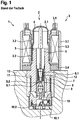
- the solenoid valve 1 which is designed, for example, as a normally open control valve, a magnet assembly 3 for generating a magnetic flux, which comprises a housing jacket 3.1, a winding carrier 3.2, a coil winding 3.3 and a cover plate 3.4, and a valve cartridge 2, which has a Capsule 2.1, a valve insert 8 pushed into the capsule 2.1 with a first end, a magnet armature 4 with a valve element 6 (also called a plunger) and a return spring 7.
- the capsule 2.1 and the valve insert 8 of the valve cartridge 2 are pressed together and the valve cartridge 2 is hydraulically sealed off from the atmosphere by a sealing weld 2.2.
- the valve insert 8 absorbs the pressure forces occurring in the hydraulic system and forwards them via a caulking flange 11 to a caulking area 12 of a fluid block 13.
- the magnet assembly 3 generates a magnetic force by energizing the coil winding 3.3 via electrical connections 3.5, which moves the longitudinally movable magnet armature 4 with the valve element 6, which includes a closing element 6.1 with a main sealing element 6.2, against the force of the return spring 7 against the valve insert 8, whereby the valve element 6 and the return spring 7 are guided in an inner bore of the valve insert 2.
- the valve insert 8 conducts the magnetic flux introduced by the magnet assembly 3 via the cover plate 3.4 axially over an air gap 5 in the direction of the magnet armature 4.
- valve insert 8 receives the so-called valve body 9 at a second end, which comprises a main valve seat 9.1 in which the The main sealing element 6.2 designed as a sealing cap is immersed in a sealing manner in order to implement the sealing function of the solenoid valve 1.
- a lower valve part 10 is placed axially on the valve insert 8 and is supported, said lower valve part comprising a check valve 10.1 arranged eccentrically to the main valve axis.
- the lower valve part 10, designed as a plastic insert, for example, also serves to seal against the surrounding fluid block 13, to seal against the valve body 9 and to accommodate a flat filter 10.2.
- valve element At least part of the valve element is arranged in a valve space delimited by the valve insert in the area of the valve seat. Furthermore, an end of the valve element facing away from the valve chamber is in operative connection with an armature.
- an end face of the armature facing the valve insert and / or an end face of the valve insert facing the end faces of the armature is designed with a surface profile such that a flow cross-section limited by the end faces varies at least regionally in the radial direction and / or in the circumferential direction of the armature.
- the tappet and armature components are installed in the valve without guiding them (ie with all degrees of freedom).
- the components are loosely mounted to one another and can therefore have a wide variety of orientations.
- the tappet is an injection-molded part
- the armature is a cold-formed steel component.
- the resulting component accuracy (especially on the armature, ram) has a very strong influence on the pressure setting accuracy.
- the most varied of component orientations between the armature and the tappet can lead to fluctuations in the pressure position (as in Fig. 2 shown), because a large number of different constellations between armature and plunger can occur and thus different magnetic forces result.
- the method according to the invention for producing a solenoid valve advantageously enables the contact situation between armature and tappet to be optimized in order to improve the accuracy of the inlet valve.
- the inventive method for producing a solenoid valve for controlling the brake pressure of a wheel brake of a slip-controllable hydraulic brake system of a motor vehicle with a longitudinally movable at least partially arranged in a valve insert and interacting with a valve seat, which in the installed position of a spring device with a acting in the opening direction with respect to the valve seat Force component is applied and can be actuated by means of an electromagnetic actuator in the closing direction with respect to the valve seat, wherein the valve element is arranged between an armature and the valve seat and is in operative connection with the armature, is characterized in that a surface unevenness of the armature (4) or the Valve element (6) is determined and based on the determined surface unevenness, the height of the projections can be dimensioned.
- a contact point between the valve element and the armature is defined by means of the projection on the end face of the valve element (also called the tappet).
- the contact between the two components is clearly defined and defined.
- a flat contact surface can also be created for the armature.
- the contact surface of the armature is designed perpendicular to the desired or required direction of movement of the armature and / or the valve element. Usually the valve element is guided closely and the armature is guided loosely. By means of the formation of a corresponding vertical contact surface, tilting of the armature during movement is avoided.
- the contact point is designed as a projection on the end face. Any type of defined structural elevation should be understood as a projection. This can take place, for example, in the form of a “pad” (also called a contact pad).
- the projection can be designed as a step. Alternatively, flowing shapes and continuous transitions are also conceivable.
- the projection can furthermore have a flat plateau surface. Alternatively, however, another form can also be present.
- the valve element is in particular injection molded and fiber-reinforced.
- the projection can be produced as part of the injection molding process. To form the projection, both an accumulation of material at the point of the projection and a recess at other points are conceivable, so that the projection is formed as a result.
- the tool required to manufacture the valve element is designed accordingly and has corresponding depressions in order to form the projection during the injection molding process.
- a projection can also be formed by a subsequent machining process, for example by means of a machining process.
- the armature and valve element are designed as two separate components.
- the anchor is a cold-formed steel component.
- the electromagnetic actuator in particular the Armature activated and operated.
- the valve element is therefore actuated in the closing direction in particular by means of the electromagnetic actuator via the armature.
- the armature moves activated by the actuator and thus also moves the valve element that is operatively connected to the armature.
- the valve element is in direct contact with the armature.
- the surface of the components has unevenness, which are, for example, production-related and can only be determined in advance to a limited extent.
- component inaccuracies If the components are reoriented (read: rotation during operation), there is usually a change in the contact points and, as a result, a change in the pressure setting accuracy.
- a defined contact point can be created through the preamble. Due to the inventive solution, there is a constant contact point even when the components are reoriented. This ensures a clear investment situation. This results in a reduction in the variation in armature tilting, which in turn causes a reduction in the magnetic force spread.
- the inventive solution thus enables a higher pressure setting accuracy of the valve.
- the projection can be formed without additional components.
- the contact point or contact points can be produced by simple manufacturing processes (for example by means of the injection molding process) and without (further, for example cutting) processing steps.
- valve element By attaching defined contact points to the valve element (tappet), it can be ensured that the system situation becomes clearer. If their height is greater than the surface unevenness on the armature (manufacturing process), it is also ensured that the contact between armature and tappet always occurs at these points. In the prior art, due to the unevenness, the contact points can change when the components are reoriented. The fluctuation of the armature tilt angle during operation is reduced by the clearer contact situation.
- the method for producing a solenoid valve is characterized in that the projection is designed as an interrupted ring; or the projection is designed as a portion of an annular element; or the projection is formed at points.
- the projection can assume any geometrical shape that is suitable for bridging spatial spacing between the end face of the valve element and the end face of the armature. This is intended to create a flat contact surface for the anchor. This can be, for example, an annular curvature over a partial area of the end face of the valve element. This could also be designed as an interrupted attached ring. Of course, a point-on-point attachment on the front side is also conceivable. It is common to all embodiments that the projection is formed only over part of the end face (facing the armature).
- the shapes described are advantageously suitable for defining a contact point with the anchor. Furthermore, the system situation can be clearly defined in this way. A suitable contact surface can also be created in order to reduce and avoid anchor tilting.
- the method for producing a solenoid valve is characterized in that a plurality of projections are formed which are positioned in the circumferential direction on the end face of the valve element.
- a plurality of projections are formed.
- at least two projections can be formed.
- these projections are distributed in the circumferential direction on the end face of the valve element.
- the distribution can also take place in a radial arrangement or a mixed arrangement, for example a star-shaped arrangement.
- These projections define the contact points between the valve element and the armature. These contact points ensure a clear installation situation and prevent the armature from tilting. The remaining part of the end face of the valve element, however, does not get into Contact with the anchor. As a result, the introduction of force can advantageously also be distributed.
- the positioning of the projections on the end face can also be achieved in a simple manner and with reduced additional manufacturing expenditure (for example when producing the tool for injection molding).
- the method for producing a solenoid valve is characterized in that a plurality of projections are formed which are positioned radially at the same distance from the central axis of the valve element.
- the method for producing a solenoid valve is characterized in that a plurality of projections are formed which are positioned circumferentially spaced from one another on the end face of the valve element.
- the plurality of projections are present. These can, for example, be designed as parts of an annular elevation on the end face. However, the respective parts (projections) do not overlap, but are spaced from one another over the circumference. This advantageously results in an improvement in the investment situation. This enables a more uniform pressure setting accuracy.
- the method for producing a solenoid valve is according to one of the preceding claims, characterized in that several projections are formed, these being positioned symmetrically distributed to the central axis on the end face of the valve element.
- the plurality of projections have, for example, the same distance from the central axis, and the distance between two adjacent projections is the same.
- the projections are preferably evenly distributed.
- the projections can also have the same depths (for example 0.35 mm) and widths (for example 0.75 mm). This advantageously enables a clear contact situation. This also allows a uniform flow of force and prevents the armature from tilting.
- the method for producing a solenoid valve is characterized in that several projections are formed, these being positioned on the outer edge of the end face of the valve element.
- the method for producing a solenoid valve is characterized in that three projections are formed.
- the method for producing a solenoid valve is characterized in that a projection is formed on each wing of the valve element.
- valve element contains axial cutouts which, for example, have a positive effect on the fluid flow, continue to remain between the Recesses wings of the valve element that allow radial guidance.
- the valve element contains axial cutouts which, for example, have a positive effect on the fluid flow, continue to remain between the Recesses wings of the valve element that allow radial guidance.
- four wings can be provided.
- a suitable distance between the contact points and the central axis can be set. In this way, an optimization of the installation situation within the existing structure and geometry of the valve element can advantageously be made possible. This enables the advantages described (in particular reduction / avoidance of tilting of the armature and a clear contact situation) without changing the basic current design of the valve element.
- the method for producing a solenoid valve is characterized in that the height of the projections is dimensioned such that it compensates for a defined surface unevenness, in particular a defined surface unevenness and an additional safety margin.
- surface unevenness can also occur on the armature or valve element in the course of the manufacturing process. This can be taken into account and compensated for by a correspondingly defined height of the projections. This can ensure that the contact between the armature and the valve element occurs at the defined contact points (and not at the undefined bumps).
- the corresponding surface unevenness and the corresponding height of the projections can be determined, for example, on the basis of measured values or simulations. For example, the height of a projection is approximately 0.025 mm to 0.075 mm, for example 0.0365 mm or 0.0499 mm. This advantageously ensures the unambiguous system situation, both in the case of regular unevenness and in the case of exceptional circumstances, for example workpieces with a limited degree of error.
- the method for producing a solenoid valve is characterized in that the surface of the projections is dimensioned in such a way that it is as small as possible and ensures permanent resistance when the valve element comes into force against the armature.
- the area or the sum of the areas of the defined contact points is therefore designed in such a way that a defined surface pressure can be transmitted.
- a force-loaded application of the valve element to the armature results both due to the spring force in the rest position and due to the spring force and actuator force during a movement.
- the area is defined in such a way that it is designed as the smallest possible area. In this way, the risk can be reduced that this hits a respective contact point on an unevenness, for example on the armature face.
- a tool for producing a valve element for a solenoid valve for controlling the brake pressure of a wheel brake of a slip-controllable hydraulic brake system of a motor vehicle is provided, the valve element being at least partially arranged in a longitudinally movable manner in a valve insert and being able to interact with a valve seat, and the valve element in the installed position of a spring device can be acted upon by a force component acting in the opening direction with respect to the valve seat and can be actuated by means of an electromagnetic actuator in the closing direction with respect to the valve seat, and wherein the valve element can be arranged between an armature and the valve seat and wherein the valve element is in operative connection with the armature, characterized in that the tool is set up to design the valve element in such a way that an end face of the valve element facing the armature has at least one projection, the V Orsprung defines a contact point with the anchor.
- This is understood to mean a tool which is set up and designed to produce a valve element as described above.
- An injection mold for producing the valve element for example, can be understood as a tool.
- This injection mold can, for example, have recesses for producing the projections on the end face of the valve element.
- FIG. 1 Fig. 3 is a schematic sectional view of a conventional solenoid valve. This has already been described as prior art.
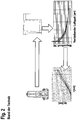
- Fig. 2 furthermore shows schematically a chain of causes and effects.
- Possible inaccuracies in the individual components are shown in the illustrations at the top left. Such inaccuracies can lead to tilting or to an inclined position of the armature, for example with respect to the valve insert. This is shown in the illustration at the top right.
- the armature and / or the valve element can still rotate. These lead to a varying inclination of the armature, for example with regard to the valve insert.
- varying inclinations of the armature cause a varying magnetic force acting on the armature. This is shown in the illustration below on the right.
- Figures 3a and 3b show embodiments for solving the problem.
- Fig. 3a defined contact points 6.3 on the face of the valve element 6 in direct plan view.
- the contact points 6.3 are defined and formed on the end face 6.4 of the valve element 6 facing the armature 4.
- a contact point 6.3 is formed on each wing of the valve element 6.
- the contact points 6.3 are positioned on the outer edge of the face 6.4, but slightly offset from the outer edge.
- the contact points 6.3 are longer in the circumferential direction than in the radial direction.
- the radial edges of the contact points 6.3 are aligned with the central axis 6.5 of the valve element 6.
- Figure 3b shows the embodiment in a side view.
- the valve element 6 is also shown here.
- the contact points 6.3 formed are attached to the end face 6.4 of the valve element 6 facing the armature 4.
- the spacing between the contact points 6.3 is also shown.
- the illustrated height of the contact points 6.3 is used for improved recognition.
- the closing element 6.1 and the main sealing element 6.2 and the spring device 7 are shown.
Landscapes
- Engineering & Computer Science (AREA)
- General Engineering & Computer Science (AREA)
- Physics & Mathematics (AREA)
- Mechanical Engineering (AREA)
- Electromagnetism (AREA)
- Transportation (AREA)
- Fluid Mechanics (AREA)
- Power Engineering (AREA)
- Magnetically Actuated Valves (AREA)
- Valves And Accessory Devices For Braking Systems (AREA)
Description
- Die vorliegende Erfindung betrifft ein Verfahren zur Herstellung eines Magnetventils zur Steuerung des Bremsdrucks einer Radbremse einer schlupfregelbaren Hydraulikbremsanlage eines Kraftfahrzeugs, mit einem längsbeweglich zumindest teilweise in einem Ventileinsatz angeordneten und mit einem Ventilsitz zusammenwirkenden Ventilelement, das in Einbaulage von einer Federeinrichtung mit einer in Öffnungsrichtung bzgl. des Ventilsitzes wirkenden Kraftkomponente beaufschlagt wird und mittels eines elektromagnetischen Aktuator in Schließrichtung bzgl. des Ventilsitzes betätigbar ist, wobei das Ventilelementes zwischen einem Anker und dem Ventilsitz angeordnet ist und mit dem Anker in Wirkverbindung steht, wobei das Magnetventil wobei eine dem Anker zugewandte Stirnseite des Ventilelements wenigstens einen Vorsprung aufweist, wobei der Vorsprung eine Kontaktstelle mit dem Anker definiert, wobei an der dem Anker (4) zugewandten Stirnseite (6.4) des Ventilelements (6) mehrere Vorsprünge (6.3) ausgebildet sind, dadurch gekennzeichnet, eine Oberflächenunebenheit des Ankers (4) oder des Ventilelements(6) ermittelt wird und anhand der ermittelten Oberflächenunebenheit die Höhe der Vorsprünge dimensioniert werden.
- Aus dem Stand der Technik ist beispielsweise die Patentanmeldung
DE 10 2007 053 134 A1 bekannt. Diese Schrift betrifft ein Magnetventil, insbesondere für ein Hydraulikaggregat, welches beispielsweise in einem Antiblockiersystem (ABS) oder einem Antriebsschlupfregelsystem (ASR-System) oder einem elektronischen Stabilitätsprogrammsystem (ESP-System) eingesetzt wird. Ein solches ist inFigur 1 dargestellt. Wie ausFigur 1 ersichtlich ist, umfasst das Magnetventil 1, das beispielsweise als stromlos offenes Regelventil ausgeführt ist, eine Magnetbaugruppe 3 zur Erzeugung eines Magnetflusses, die einen Gehäusemantel 3.1, einen Wicklungsträger 3.2, eine Spulenwicklung 3.3 und eine Abdeckscheibe 3.4 umfasst, und eine Ventilpatrone 2, die eine Kapsel 2.1, einen mit einem ersten Ende in die Kapsel 2.1 eingeschobenen Ventileinsatz 8, einen Magnetanker 4 mit einem Ventilelement 6 (auch Stößel genannt) und eine Rückstellfeder 7 umfasst. Bei der Herstellung des Magnetventils 1 werden die Kapsel 2.1 und der Ventileinsatz 8 der Ventilpatrone 2 durch Pressen aufeinander gefügt und durch eine Dichtschweißung 2.2 wird die Ventilpatrone 2 hydraulisch gegenüber der Atmosphäre abgedichtet. Zusätzlich nimmt der Ventileinsatz 8 die im hydraulischen System auftretenden Druckkräfte auf und leitet diese über einen Verstemmflansch 11 an einen Verstemmbereich 12 eines Fluidblocks 13 weiter. - Die Magnetbaugruppe 3 erzeugt durch eine Bestromung der Spulenwicklung 3.3 über elektrischen Anschlüsse 3.5 eine Magnetkraft, die den längsbeweglichen Magnetanker 4 mit dem Ventilelement 6, der ein Schließelement 6.1 mit einem Hauptdichtelement 6.2 umfasst, entgegen der Kraft der Rückstellfeder 7 gegen den Ventileinsatz 8 bewegt, wobei das Ventilelement 6 und die Rückstellfeder 7 in einer Innenbohrung des Ventileinsatzes 2 geführt sind. Der Ventileinsatz 8 leitet den von der Magnetbaugruppe 3 über die Abdeckscheibe 3.4 eingeleiteten Magnetfluss axial über einen Luftspalt 5 in Richtung Magnetanker 4. Zudem nimmt der Ventileinsatz 8 an einem zweiten Ende den so genannten Ventilkörper 9 auf, der einen Hauptventilsitz 9.1 umfasst, in welchen das als Dichtkalotte ausgeführte Hauptdichtelement 6.2 dichtend eintaucht, um die Dichtfunktion des Magnetventils 1 umzusetzen. Wie weiter aus
Figur 1 ersichtlich ist, wird an den Ventileinsatz 8 axial ein Ventilunterteil 10 angelegt und abgestützt, das ein exzentrisch zur Ventilhauptachse angeordnetes Rückschlagventil 10.1 umfasst. Das beispielsweise als Kunststoffeinsatz ausgeführte Ventilunterteil 10 dient zusätzlich zur Abdichtung zum umgebenden Fluidblock 13, zur Abdichtung zum Ventilkörper 9 und zur Aufnahme eines Flachfilters 10.2. - Weiterhin ist aus dem Stand der Technik die Patentanmeldung
DE 10 2004 030 428 A1 bekannt. Diese Schrift betrifft eine elektromagnetische Ventilvorrichtung. Wenigstens ein Teil des Ventilelementes ist in einem von dem Ventileinsatz im Bereich des Ventilsitzes begrenzten Ventilraum angeordnet. Des Weiteren steht ein dem Ventilraum abgewandtes Ende des Ventilelementes mit einem Anker in Wirkverbindung. Hierbei ist eine dem Ventileinsatz zugewandte Stirnseite des Ankers und/oder eine der Stirnseiten des Ankers zugewandte Stirnseite des Ventileinsatzes mit einem derartigen Oberflächenprofil ausgeführt, dass ein von den Stirnseiten begrenzter Strömungsquerschnitt in radialer Richtung und/oder in Umfangsrichtung des Ankers wenigstens bereichsweise variiert. - Weiterhin ist aus dem Stand der Technik die Patentanmeldung
US 2001/050347 A1 bekannt. Diese Schrift betrifft ein Magnetventil. Dieses enthält einen einen Stößel aus magnetisches Material mit einer Endfläche sowie einem beweglichen Teil, wobei an dem Ende des beweglichen Teils ein Vorsprung ausgebildet ist, welcher an der Endfläche des Stößels anliegt. - Weiterhin ist aus dem Stand der Technik die Patentanmeldung
DE 102 53 769 A1 bekannt. Diese Schrift betrifft ein Magnetventil, welches dadurch gekennzeichnet ist, dass der Stößel durch eine zwischen seinen beiden Enden verlaufende Bohrung eine rohrförmige, hohle Form aufweist, und dass das im Stößel geführte Schließglied Ausnehmungen aufweist, über welche Druckmittel von der Ventilkammer in die Bohrung des Stößels strömen kann. - Weiterhin ist aus dem Stand der Technik die Patentanmeldung
WO 01/00473A1 - Weiterhin ist aus dem Stand der Technik die Patentanmeldung
EP 1 647 460 A1 bekannt. Diese Schrift betrifft ein Elektromagnetventil mit einer Vielzahl von Vorsprüngen welche auf der Oberfläche des Ankers ausgebildet sind, die den Magnetkern berührt. - Im Allgemeinen werden die Bauteile Stößel und Anker ungeführt (d.h. mit allen Freiheitsgraden) in das Ventil verbaut. Zudem sind die Bauteile zu einander lose montiert und können somit unterschiedlichste Orientierungen aufweisen. Bei dem Stößel handelt es sich um ein Spritzgussteil, beim Anker um ein kaltumgeformtes Stahlbauteil. Die daraus resultierende Bauteilgenauigkeit (vor allem an Anker, Stößel) beeinflusst die Druckstellgenauigkeit sehr stark. Zudem können unterschiedlichste Bauteilorientierungen zwischen Anker und Stößel zu Schwankungen bei der Druckstellung kommen (wie in
Fig. 2 dargestellte), weil sich eine Vielzahl unterschiedlicher Konstellationen zwischen Anker und Stößel einstellen kann und sich somit unterschiedliche Magnetkräfte ergeben. - Vorteilhaft ermöglicht hingegen das erfindungsgemäße Verfahren zur Herstellung eines Magnetventils eine Optimierung der Kontaktsituation zwischen Anker und Stößel zur Verbesserung der Genauigkeit des Einlassventils. Ermöglicht wird dies gemäß der Erfindung durch die Merkmale des unabhängigen Patentanspruchs. Weiterbildungen der Erfindung sind in den abhängigen Patentansprüchen angegeben.
- Das erfindungsgemäße Verfahren zur Herstellung eines Magnetventils zur Steuerung des Bremsdrucks einer Radbremse einer schlupfregelbaren Hydraulikbremsanlage eines Kraftfahrzeugs, mit einem längsbeweglich zumindest teilweise in einem Ventileinsatz angeordneten und mit einem Ventilsitz zusammenwirkenden Ventilelement, das in Einbaulage von einer Federeinrichtung mit einer in Öffnungsrichtung bzgl. des Ventilsitzes wirkenden Kraftkomponente beaufschlagt wird und mittels eines elektromagnetischen Aktuator in Schließrichtung bzgl. des Ventilsitzes betätigbar ist, wobei das Ventilelementes zwischen einem Anker und dem Ventilsitz angeordnet ist und mit dem Anker in Wirkverbindung steht, ist dadurch gekennzeichnet, dass eine Oberflächenunebenheit des Ankers (4) oder des Ventilelements(6) ermittelt wird und anhand der ermittelten Oberflächenunebenheit die Höhe der Vorsprünge dimensioniert werden.
- Hierunter wird verstanden, dass mittels des Vorsprungs an der Stirnseite des Ventilelements (auch Stößel genannt) eine Anlagestelle zwischen dem Ventilelement und dem Anker definiert wird. Der Kontakt zwischen beiden Komponenten ist dadurch klar bestimmt und festgelegt. Weiterhin kann mittels des Vorsprungs als Anlagestelle (sowie zumindest einer weiteren Anlagestelle) auch eine ebene Anlagefläche für den Anker geschaffen werden. Insbesondere ist hierbei von Vorteil, wenn die Anlagefläche des Ankers senkrecht zur gewünschten oder erforderlichen Bewegungsrichtung des Ankers und/oder des Ventilelements ausgebildet ist. Zumeist ist das Ventilelement eng geführt und der Anker lose geführt. Mittels der Ausbildung einer entsprechenden senkrechten Anlagefläche wird ein Verkippen des Ankers bei der Bewegung vermieden.
- Die Kontaktstelle ist als Vorsprung der Stirnseite ausgebildet. Als Vorsprung soll jede Art von definierter baulicher Erhebung verstanden werden. Dies kann bspw. in Form eines "Pad" (auch Kontaktpads genannt) erfolgen. Bspw. kann der Vorsprung als Stufe ausgebildet sein. Alternativ sind auch fließende Formen und kontinuierliche Übergänge denkbar. Der Vorsprung kann weiterhin eine ebene Plateaufläche aufweisen. Alternativ kann jedoch auch eine andere Form vorliegen. Das Ventilelement ist insbesondere spritzgegossen und faserverstärkt. Die Herstellung des Vorsprungs kann im Rahmen des Spritzgussprozesses erfolgen. Zur Ausbildung des Vorsprungs ist sowohl eine Materialanhäufung an der Stelle des Vorsprungs als auch eine Vertiefung an anderen Stellen denkbar, so dass sich der Vorsprung hierdurch bildet. Das zur Herstellung des Ventilelements erforderliche Werkzeug ist entsprechend ausgestaltet und weist entsprechende Vertiefungen auf, um den Vorsprung beim Spritzgußprozess auszubilden. Alternativ kann ein Vorsprung auch durch ein anschließendes Bearbeitungsverfahren gebildet werde, bspw. mittels eines spanenden Bearbeitungsprozesses.
- Weiterhin sei darauf verwiesen, dass Anker und Ventilelement als zwei separate Bauteile ausgebildet sind. Hierbei ist der Anker ein kaltumgeformtes Stahlbauteil. Hierdurch wird mittels des elektromagnetischen Aktuators insbesondere der Anker aktiviert und betätigt. Das Ventilelement wird daher insbesondere mittels des elektromagnetischen Aktuators über den Anker in Schließrichtung betätigt. Der Anker bewegt sich aktiviert durch den Aktuator und bewegt damit auch das mit dem Anker in Wirkverbindung stehende Ventilelement. Das Ventilelement steht dabei in direktem Kontakt mit dem Anker.
- Die Oberfläche der Komponenten besitzt jedoch Unebenheiten, die bspw. produktionsbedingt sind und nur im begrenzten Maße voraus zu bestimmen. Ebenfalls bestehen Bauteilungenauigkeiten. Hierbei kommt es bei einer Neuorientierung der Bauteile (sprich: Drehung im Betrieb) normalerweise zu einer Änderung der Kontaktstellen und dadurch eine Änderung der Druckstellgenauigkeit. Jedoch kann durch den Vorspruch eine definierte Kontaktstelle geschaffen werden. Durch die erfinderische Lösung besteht auch bei einer Neuorientierung der Bauteile eine gleichbleibende Kontaktstelle. Hierdurch wird eine eindeutige Anlagesituation sichergestellt. Hierdurch erfolgt eine Reduzierung der Variation des Ankerverkippens, was wiederum eine Verringerung der Magnetkraftstreuung bewirkt. Durch die erfinderische Lösung wird somit eine höhere Druckstellgenauigkeit des Ventils ermöglicht.
- Vorteilhaft ist dabei weiterhin, dass der Vorsprung ohne zusätzlichen Komponenten gebildet werden kann. Die Erzeugung der Kontaktstelle oder der Kontaktstellen kann durch einfache Fertigungsverfahren (bspw. mittels des Spritzgussprozesses), sowie ohne (weitere, bspw. spanende) Bearbeitungsschritte erfolgen.
- Durch Anbringung von definierten Kontaktstellen am Ventilelement (Stößel) kann sichergestellt werden, dass sich die Anlagesituation eindeutiger wird. Wenn deren Höhe größer ist als die auftretende Oberflächenunebenheit am Anker (Herstellprozess) ist zudem sichergestellt, dass der Kontakt zwischen Anker und Stößel stets an diesen Punkten auftritt. In Stand der Technik können sich aufgrund der Unebenheiten die Anlagepunkte bei Neuorientierung der Bauteile verändern. Die auftretende Schwankung der Ankerkippwinkel im Betrieb reduziert sich durch die eindeutigere Kontaktsituation.
- In einer vorteilhaften Ausführung ist das Verfahren zur Herstellung eines Magnetventils dadurch gekennzeichnet, dass der Vorsprung als unterbrochener Ring ausgebildet ist; oder der Vorsprung als Teilbereich eines ringförmigen Elements ausgebildet ist; oder der Vorsprung punktuell ausgebildet ist.
- Hierunter wird verstanden, dass der Vorsprung jegliche geometrische Form annehmen kann, die geeignet ist eine bereichsweise räumliche Distanzierung der Stirnseite des Ventilelements mit der Stirnseite des Ankers zu überbrücken. Hierdurch soll eine ebene Anlagefläche für den Anker geschaffen werden. Dies kann bspw. eine ringförmige Wölbung über einen Teilbereich der Stirnseite des Ventilelements sein. Ebenfalls könnte dies als unterbrochener aufgesetzter Ring ausgebildet sein. Selbstverständlich ist auch ein punktuell ausgebildeter Vorsatz auf der Stirnseite denkbar. Allen Ausführungsformen ist zu eigen, dass der Vorsprung lediglich über einen Teil der (dem Anker zugewandten) Stirnseite ausgebildet ist.
- Vorteilhaft eignen sich die beschriebenen Formen, um eine Kontaktstelle mit dem Anker zu definieren. Weiterhin kann hierdurch die Anlagesituation eindeutig definiert werden. Ebenso kann eine geeignete Anlagefläche geschaffen werden, um ein Ankerkippen zu reduzieren und zu vermeiden.
- In einer möglichen Ausgestaltung ist das Verfahren zur Herstellung eines Magnetventils dadurch gekennzeichnet, dass mehrere Vorsprünge ausgebildet sind, welche in Umfangsrichtung auf der Stirnseite des Ventilelementes positioniert sind.
- Hierunter wird verstanden, dass mehrere Vorsprünge ausgebildet sind. Bspw. können wenigstens zwei Vorsprünge ausgebildet sein. In einer Ausführung sind diese Vorsprünge in Umfangsrichtung auf der Stirnseite des Ventilelements verteilt. In einer alternativen Ausführung kann die Verteilung auch in einer radialen Anordnung oder einer gemischten Anordnung, bspw. sternförmigen Anordnung erfolgen. Diese Vorsprünge definieren die Kontaktstellen zwischen dem Ventilelement und dem Anker. Diese Kontaktstellen stellen eine eindeutige Anlagesituation sicher und vermeiden ein Verkippen des Ankers. Der verbleibende Teil der Stirnseite des Ventilelements gelangt hingegen nicht in Kontakt mit dem Anker. Vorteilhaft kann hierdurch weiterhin eine Verteilung der Krafteinleitung erfolgen. Ebenfalls ist die Positionierung der Vorsprünge an der Stirnseite auf einfache Weise und mit reduziertem zusätzlichem Fertigungsaufwand (bspw. bei der Herstellung des Werkzeugs für den Spritzguss) erzielbar.
- In einer bevorzugten Ausführung ist das Verfahren zur Herstellung eines Magnetventils dadurch gekennzeichnet, dass mehrere Vorsprünge ausgebildet sind, welche radial im selben Abstand zur Mittelachse des Ventilelements positioniert sind.
- Hierunter wird verstanden, dass die Vorsprünge im Wesentlichen in gleicher Entfernung von der Mittelachse des Ventilelements angeordnet sind. Vorteilhaft kann hierdurch eine eindeutige Kontaktsituation geschaffen werden und ein Verkippen des Ankers auf eine bestimmte Seite reduziert und weitgehend vermieden werden. Weiterhin ergibt sein ein gleichmäßigerer Kraftfluss.
- In einer alternativen Weiterbildung ist das Verfahren zur Herstellung eines Magnetventils dadurch gekennzeichnet, dass mehrere Vorsprünge ausgebildet sind, welche auf der Stirnseite des Ventilelements zirkumferentiell voneinander beabstandet positioniert sind.
- Hierunter wird verstanden, dass die mehrere Vorsprünge vorhanden sind. Diese können bspw. als Teile einer ringförmigen Erhebung auf der Stirnseite ausgebildet sein. Die jeweiligen Teile (Vorsprünge) überdecken sich jedoch nicht, sondern sind über den Umfang von einander beabstandet. Vorteilhaft ergibt sich dadurch eine Verbesserung der Anlagesituation. Hierdurch wird eine einheitlichere Druckstellgenauigkeit ermöglicht.
- In einer vorteilhaften Ausgestaltung ist das Verfahren zur Herstellung eines Magnetventils nach einem der vorhergehenden Ansprüche, dadurch gekennzeichnet, dass mehrere Vorsprünge ausgebildet sind, wobei diese symmetrisch verteilt zur Mittelachse auf der Stirnseite des Ventilelements positioniert sind.
- Hierunter wird verstanden, dass die mehreren Vorsprünge bspw. denselben Abstand zur Mittelachse aufweisen, sowie der Abstand zweier benachbarter Vorsprünge gleich ist. Vorzugsweise sind die Vorsprünge gleichmäßig verteilt. Ebenfalls können die Vorsprünge die gleiche Tiefen (bspw. 0,35 mm) und Breiten (bspw. 0,75 mm) aufweisen. Vorteilhaft wird hierdurch eine eindeutige Kontaktsituation ermöglich. Dies erlaubt weiterhin einen gleichmäßigen Kraftfluss und verhindert ein Verkippen des Ankers.
- In einer möglichen Ausführung ist das Verfahren zur Herstellung eines Magnetventils dadurch gekennzeichnet, dass mehrere Vorsprünge ausgebildet sind, wobei diese am äußeren Rand der Stirnseite des Ventilelements positioniert sind.
- Hierunter wird verstanden, dass die Vorsprünge so positioniert sind, dass diese den weitest möglichen Abstand zur Mittelachse aufweisen. Hierdurch kann vorteilhaft ein Verkippen des Ankers bei einer Bewegung reduziert oder vermieden werden.
- In einer bevorzugten Weiterbildung ist das Verfahren zur Herstellung eines Magnetventils dadurch gekennzeichnet, dass drei Vorsprünge ausgebildet sind.
- Hierunter wird verstanden, dass exakt drei Vorsprünge an der Stirnseite des Ventilelements definiert sind. Durch die Festlegung auf diese Anzahl kann eine Überbestimmung der Kontaktsituation vermieden werden. Hierdurch wird ein "Kippeln" des Ankers aufgrund der geometrischen Überbestimmung verhindert.
- In einer alternativen Ausführung sind jedoch auch vier oder 5 Vorsprünge denkbar.
- In einer alternativen Ausführungsform ist das Verfahren zur Herstellung eines Magnetventils dadurch gekennzeichnet, dass an jedem Flügel des Ventilelements jeweils ein Vorsprung ausgebildet ist.
- Hierunter wird verstanden, dass das Ventilelement axiale Aussparungen enthält, die bspw. den Fluidfluss positiv beeinflussen, weiterhin verbleiben zwischen den Aussparungen Flügel des Ventilelements, die eine radiale Führung ermöglichen. Bspw. können vier Flügel vorgesehen sein. Durch eine Positionierung der Kontaktstellen an den Flügeln, kann ein geeigneter Abstand der Kontaktstellen von der Mittelachse eingestellt werden. Vorteilhaft kann hierdurch eine Optimierung der Anlagesituation innerhalb der bestehenden Struktur und Geometrie des Ventilelements ermöglicht werden. Dies ermöglicht die beschriebenen Vorteile (insbesondere Reduzierung/Vermeidung Verkippen des Ankers sowie eindeutige Kontaktsituation) ohne Änderung des prinzipiellen aktuellen Designs des Ventilelements.
- In einer vorteilhaften Ausgestaltung ist das Verfahren zur Herstellung eines Magnetventils dadurch gekennzeichnet, dass die Höhe der Vorsprünge derart dimensioniert ist, dass diese eine definierte Oberflächenunebenheit ausgleicht, insbesondere eine definierte Oberflächenunebenheit sowie einen zusätzlichen Sicherheitsaufschlag.
- Hierunter wird verstanden, dass im Rahmen des Herstellungsprozesses auch Oberflächenunebenheiten am Anker oder Ventilelement auftreten können. Durch eine entsprechend definierte Höhe der Vorsprünge kann diese berücksichtigt und ausgeglichen werden. Hierdurch kann sichergestellt werden, dass der Kontakt zwischen dem Anker und dem Ventilelement an den definierten Kontaktstellen auftritt (und nicht an den nicht definierten Unebenheiten). Die entsprechenden Oberflächenunebenheiten sowie die entsprechende Höhe der Vorsprünge kann bspw. aufgrund Messwerte oder Simulationen ermittelt werden. Bspw. liegt die Höhe eines Vorsprungs bei etwa 0,025 mm bis 0,075 mm, bspw. bei 0,0365 mm oder bei 0,0499 mm. Vorteilhaft erfolgt hiermit eine Sicherstellung der eindeutigen Anlagesituation, sowohl bei regulären Unebenheiten, als auch bei außergewöhnlichen Umständen, bspw. Werkstücken mit bedingtem Fehlermaß.
- In einer möglichen Ausgestaltung ist das Verfahren zur Herstellung eines Magnetventils dadurch gekennzeichnet, dass die Fläche der Vorsprünge derart dimensioniert ist, dass diese kleinstmöglich ist sowie eine dauerhafte Beständigkeit bei einem kraftbeaufschlagten Anliegen des Ventilelements an dem Anker gewährleistet.
- Hierunter ist zu verstehen, dass die gesamte Flächenpressung auf die vorhandenen in Kontakt stehenden Flächen der Kontaktstellen verteilt wird. Die Fläche, bzw. die Summe der Flächen der definierten Kontaktstellen ist daher so ausgelegt, dass eine definierte Flächenpressung übertragen werden kann. Ein derart kraftbeaufschlagtes Anliegen des Ventilelements an den Anker ergibt sich sowohl aufgrund der Federkraft in Ruhestellung, als auch aufgrund der Federkraft sowie Aktuatorkraft bei einer Bewegung. Weiterhin ist die Fläche derart definiert, dass diese als kleinstmögliche Fläche ausgestaltet ist. Hierdurch kann das Risiko reduziert werden, dass diese auf eine jeweilige Kontaktstelle auf eine Unebenheit bspw. bei der Ankerstirnseite trifft.
- Weiterhin ist ein Werkzeug zur Herstellung eines Ventilelements für ein Magnetventil zur Steuerung des Bremsdrucks einer Radbremse einer schlupfregelbaren Hydraulikbremsanlage eines Kraftfahrzeugs, vorgesehen, wobei das Ventilelement längsbeweglich zumindest teilweise in einem Ventileinsatz angeordnet werden und mit einem Ventilsitz zusammenwirken kann, und wobei das Ventilelement in Einbaulage von einer Federeinrichtung mit einer in Öffnungsrichtung bezüglich des Ventilsitzes wirkenden Kraftkomponente beaufschlagbar ist und mittels eines elektromagnetischen Aktuator in Schließrichtung bezüglich des Ventilsitzes betätigbar ist, und wobei das Ventilelement zwischen einem Anker und dem Ventilsitz angeordnet werden kann und wobei das Ventilelement mit dem Anker in Wirkverbindung steht, dadurch gekennzeichnet, dass das Werkzeug eingerichtet ist das Ventilelement derart auszubilden, dass eine dem Anker zugewandte Stirnseite des Ventilelements wenigstens einen Vorsprung aufweist, wobei der Vorsprung eine Kontaktstelle mit dem Anker definiert.
- Hierunter wird ein Werkzeug verstanden, welches eingerichtet und ausgebildet ist, ein wie oben beschriebenes Ventilelement zu erzeugen. Als Werkzeug kann bspw. eine Spritzgussform zur Herstellung des Ventilelements verstanden werden. Diese Spritzgussform kann bspw. Aussparungen zur Erzeugung der Vorsprünge der Stirnfläche des Ventilelements aufweisen.
- Es ist darauf hinzuweisen, dass die in der Beschreibung einzeln aufgeführten Merkmale in beliebiger, technisch sinnvoller Weise miteinander kombiniert werden können und weitere Ausgestaltungen der Erfindung aufzeigen. Weitere Merkmale und Zweckmäßigkeit der Erfindung ergeben sich aus der Beschreibung von Ausführungsbeispielen anhand der beigefügten Figuren.
- Von den Figuren zeigt:
-
Fig. 1 eine schematische Schnittansicht eines herkömmlichen Magnetventils; und -
Fig. 2 eine schematische Ursachen- und Wirkungskette hinsichtlich der Druckstellgenauigkeit und dem Ankerkippwinkel; und -
Fig. 3a eine schematische Ansicht eines Ausführungsbeispiels eines Ventilelements mit ausgebildeten Kontaktstellen in Aufsicht, und -
Fig. 3b eine schematische Ansicht eines Ausführungsbeispiels eines Ventilelements mit ausgebildeten Kontaktstellen in Seitenansicht. - In
Fig. 1 ist eine schematische Schnittansicht eines herkömmlichen Magnetventils gezeigt. Dieses wurde bereits als Stand der Technik beschrieben. -
Fig. 2 zeigt weiterhin schematisch eine Ursachen- und Wirkungskette. Hierbei werden in den Darstellungen links oben mögliche Ungenauigkeiten in den einzelnen Bauteilen dargestellt. Solche Ungenauigkeiten können zu einem Verkippen, bzw. zu einer Schrägstellung des Ankers bspw. hinsichtlich dem Ventileinsatz führen. Dies ist in der Darstellung rechts oben gezeigt. Bei einem Einsatz des Ventils kann es weiterhin zu Drehungen des Ankers und/oder des Ventilelements kommen. Diese führen zu einer variierenden Schrägstellung des Ankers bspw. hinsichtlich dem Ventileinsatz. Variierende Schrägstellungen des Ankers verursachen jedoch eine variierende auf den Anker wirkende Magnetkraft. Dies ist in der Darstellung rechts unten gezeigt. Die variierende auf den Anker wirkende Magnetkraft führt wiederum zu einer unterschiedlichen Strom-/Druck-Charakteristik des Ventils, wie dies in der Darstellung unten links abgebildet ist. Einfache Unebenheiten in den Komponenten verursachen damit unterschiedliche Leistungscharakteristiken bei unterschiedlichen Ventilen - vielmehr sogar werden damit unterschiedliche Charakteristiken bei ein und demselben Ventil während des Betriebs des Ventils erzeugt. -
Fig. 3a und Fig. 3b zeigen Ausführungsformen zur Lösung des Problems. Hierbei zeigtFig. 3a definierte Kontaktstellen 6.3 auf der Stirnseite des Ventilelements 6 in direkten Aufsicht. Die Kontaktstellen 6.3 sind auf der zum Anker 4 weisenden Stirnseite 6.4 des Ventilelements 6 definiert und ausgebildet. Hierbei ist auf jedem Flügel des Ventilelements 6 jeweils eine Kontaktstelle 6.3 ausgebildet. Die Kontaktstellen 6.3 sind am äußeren Rand der Stirnseite 6.4 positioniert, jedoch leicht von der Außenkante abgesetzt. Die Kontaktstellen 6.3 sind in Umfangsrichtung länger als in radialer Richtung. Die radialen Kanten der Kontaktstellen 6.3 sind auf die Mittelachse 6.5 des Ventilelements 6 ausgerichtet. -
Fig. 3b zeigt das Ausführungsbeispiel in einer Seitenansicht. Hierbei ist ebenfalls das Ventilelement 6 dargestellt. Man sieht dabei deutlich, dass die ausgebildeten Kontaktstellen 6.3 auf der dem Anker 4 zugewandten Stirnseite 6.4 des Ventilelements 6 angebracht sind. Weiterhin ist auch die Beabstandung der Kontaktstellen 6.3 dargestellt. Die dargestellte Höhe der Kontaktstellen 6.3 dient der verbesserten Erkennung. Weiterhin sind das Schließelement 6.1 sowie das Hauptdichtelement 6.2 und die Federeinrichtung 7 dargestellt.
Claims (12)
- Verfahren zur Herstellung eines Magnetventils (1) zur Steuerung eines Bremsdrucks einer Radbremse einer schlupfregelbaren Hydraulikbremsanlage eines Kraftfahrzeugs,mit einem längsbeweglich zumindest teilweise in einem Ventileinsatz (8) angeordneten und mit einem Ventilsitz (9.1) zusammenwirkenden Ventilelement (6), das in Einbaulage von einer Federeinrichtung (7) mit einer in Öffnungsrichtung bzgl. des Ventilsitzes (9.1) wirkenden Kraftkomponente beaufschlagt wird und mittels eines elektromagnetischen Aktuators (3) in Schließrichtung bzgl. des Ventilsitzes (9.1) betätigbar ist,wobei das Ventilelementes (6) zwischen einem Anker (4) und dem Ventilsitz (9.1) angeordnet ist und mit dem Anker (4) in Wirkverbindung steht,wobei eine dem Anker (4) zugewandte Stirnseite (6.4) des Ventilelements wenigstens einen Vorsprung (6.3) aufweist, wobei der Vorsprung (6.3) eine Kontaktstelle mit dem Anker (4) definiert, wobei an der dem Anker (4) zugewandten Stirnseite (6.4) des Ventilelements (6) mehrere Vorsprünge (6.3) ausgebildet sind, dadurch gekennzeichnet, dass eine Oberflächenunebenheit des Ankers (4) oder des Ventilelements(6) ermittelt wird und anhand der ermittelten Oberflächenunebenheit die Höhe der Vorsprünge dimensioniert werden.
- Verfahren zur Herstellung eines Magnetventils (1) nach Anspruch 1, dadurch gekennzeichnet, dass- der Vorsprung (6.3) als unterbrochener Ring ausgebildet ist; oder- der Vorsprung (6.3) als Teilbereich eines ringförmigen Elements ausgebildet ist; oder- der Vorsprung (6.3) punktuell ausgebildet ist.
- Verfahren zur Herstellung eines Magnetventils (1) nach einem der vorhergehenden Ansprüche, dadurch gekennzeichnet, dass mehrere Vorsprünge (6.3) ausgebildet sind, welche in Umfangsrichtung auf der Stirnseite (6.4) des Ventilelementes (6) positioniert sind.
- Verfahren zur Herstellung eines Magnetventils (1) nach einem der vorhergehenden Ansprüche, dadurch gekennzeichnet, dass mehrere Vorsprünge (6.3) ausgebildet sind, welche radial im selben Abstand zur Mittelachse (6.5) des Ventilelements (6) positioniert sind.
- Verfahren zur Herstellung eines Magnetventils (1) nach einem der vorhergehenden Ansprüche, dadurch gekennzeichnet, dass mehrere Vorsprünge (6.3) ausgebildet sind, welche auf der Stirnseite (6.4) des Ventilelements (6) zirkumferentiell voneinander beabstandet positioniert sind.
- Verfahren zur Herstellung eines Magnetventils (1) nach einem der vorhergehenden Ansprüche, dadurch gekennzeichnet, dass mehrere Vorsprünge (6.3) ausgebildet sind, wobei diese symmetrisch verteilt zur Mittelachse (6.5) auf der Stirnseite (6.4) des Ventilelements (6) positioniert sind.
- Verfahren zur Herstellung eines Magnetventils (1) nach einem der vorhergehenden Ansprüche, dadurch gekennzeichnet, dass mehrere Vorsprünge (6.3) ausgebildet sind, wobei diese am äußeren Rand der Stirnseite (6.4) des Ventilelements (6) positioniert sind.
- Verfahren zur Herstellung eines Magnetventils (1) nach einem der vorhergehenden Ansprüche, dadurch gekennzeichnet, dass drei Vorsprünge (6.3) ausgebildet sind.
- Verfahren zur Herstellung eines Magnetventils (1) nach einem der vorhergehenden Ansprüche, dadurch gekennzeichnet, dass das Ventilelement (6) mehrere Flügel zur radialen Führung des Ventilelements (6) aufweist, wobei an jedem Flügel des Ventilelements (6) jeweils ein Vorsprung (6.3) ausgebildet ist.
- Verfahren zur Herstellung eines Magnetventils (1) nach einem der vorhergehenden Ansprüche, dadurch gekennzeichnet, dass die Höhe des Vorsprungs (6.3) derart dimensioniert ist, dass diese eine ermittelte Oberflächenunebenheit des Ankers (4) oder des Ventilelements (6) sowie einen zusätzlichen Sicherheitsaufschlag ausgleicht.
- Verfahren zur Herstellung eines Magnetventils (1) nach einem der vorhergehenden Ansprüche, dadurch gekennzeichnet, dass die Fläche des Vorsprungs (6.3) derart dimensioniert ist, dass diese eine dauerhafte Beständigkeit bei einem kraftbeaufschlagten Anliegen des Ventilelements (6) an dem Anker (4) gewährleistet und nicht größer ist als notwendig um eine dauerhafte Beständigkeit bei einem kraftbeaufschlagten Anliegen des Ventilelements (6) an dem Anker (4) zu gewährleisten.
- Magnetventil (1) zur Steuerung eines Bremsdrucks einer Radbremse einer schlupfregelbaren Hydraulikbremsanlage eines Kraftfahrzeugs, mit einem längsbeweglich zumindest teilweise in einem Ventileinsatz (8) angeordneten und mit einem Ventilsitz (9.1) zusammenwirkenden Ventilelement (6), das in Einbaulage von einer Federeinrichtung (7) mit einer in Öffnungsrichtung bzgl. des Ventilsitzes (9.1) wirkenden Kraftkomponente beaufschlagt wird und mittels eines elektromagnetischen Aktuators (3) in Schließrichtung bzgl. des Ventilsitzes (9.1) betätigbar ist, wobei das Ventilelementes (6) zwischen einem Anker (4) und dem Ventilsitz (9.1) angeordnet ist und mit dem Anker (4) in Wirkverbindung steht, wobei eine dem Anker (4) zugewandte Stirnseite (6.4) des Ventilelements wenigstens einen Vorsprung (6.3) aufweist, wobei der Vorsprung (6.3) eine Kontaktstelle mit dem Anker (4) definiert, wobei an der dem Anker (4) zugewandten Stirnseite (6.4) des Ventilelements (6) mehrere Vorsprünge (6.3) ausgebildet sind, dadurch gekennzeichnet, dass das Magnetventil (1) durch ein Verfahren nach einem der vorhergehenden Ansprüche hergestellt worden ist, wobei zumindest eine Oberflächenunebenheit des Ankers (4) oder des Ventilelements(6) ermittelt worden ist und anhand der ermittelten Oberflächenunebenheit die Höhe der Vorsprünge dimensioniert worden ist.
Applications Claiming Priority (2)
| Application Number | Priority Date | Filing Date | Title |
|---|---|---|---|
| DE102016220348.7A DE102016220348A1 (de) | 2016-10-18 | 2016-10-18 | Magnetventil zur Steuerung des Bremsdrucks einer Radbremse |
| PCT/EP2017/073828 WO2018072958A1 (de) | 2016-10-18 | 2017-09-20 | Magnetventil zur steuerung des bremsdrucks einer radbremse und werkzeug zur herstellung seines ventilelements |
Publications (2)
| Publication Number | Publication Date |
|---|---|
| EP3529114A1 EP3529114A1 (de) | 2019-08-28 |
| EP3529114B1 true EP3529114B1 (de) | 2021-11-10 |
Family
ID=59914489
Family Applications (1)
| Application Number | Title | Priority Date | Filing Date |
|---|---|---|---|
| EP17769098.9A Active EP3529114B1 (de) | 2016-10-18 | 2017-09-20 | Magnetventil zur steuerung des bremsdrucks einer radbremse und werkzeug zur herstellung seines ventilelements |
Country Status (7)
| Country | Link |
|---|---|
| US (1) | US10969032B2 (de) |
| EP (1) | EP3529114B1 (de) |
| JP (1) | JP7223687B2 (de) |
| KR (1) | KR102407309B1 (de) |
| CN (1) | CN109843666B (de) |
| DE (1) | DE102016220348A1 (de) |
| WO (1) | WO2018072958A1 (de) |
Families Citing this family (2)
| Publication number | Priority date | Publication date | Assignee | Title |
|---|---|---|---|---|
| DE112020006812B4 (de) | 2020-02-27 | 2025-02-13 | Pierburg Gmbh | Elektromagnetventil für einen Kälte- oder Klimakreislauf |
| DE102020112636A1 (de) * | 2020-05-11 | 2021-11-11 | Fte Automotive Gmbh | Magnetventil sowie Pumpeneinheit mit einem solchen Magnetventil |
Family Cites Families (21)
| Publication number | Priority date | Publication date | Assignee | Title |
|---|---|---|---|---|
| JPS5440519U (de) | 1977-08-26 | 1979-03-17 | ||
| JPH07239050A (ja) | 1994-02-25 | 1995-09-12 | Mitsubishi Electric Corp | 流体制御弁、その制御磁路手段、その耐摩耗性手段およびその減衰手段 |
| WO2001000473A1 (de) | 1999-06-23 | 2001-01-04 | Continental Teves Ag & Co. Ohg | Elektromagnetventil, insbesondere für hydraulische bremsanlagen mit schlupfregelung |
| DE19936711A1 (de) | 1999-06-23 | 2001-01-11 | Continental Teves Ag & Co Ohg | Elektromagnetventil, insbesondere für hyraulische Bremsanlagen mit Schlupfregelung |
| JP3781948B2 (ja) | 2000-06-08 | 2006-06-07 | 株式会社日立製作所 | 電磁弁 |
| JP2002174356A (ja) | 2000-12-06 | 2002-06-21 | Aisin Seiki Co Ltd | 電磁弁 |
| JP2002347597A (ja) | 2001-05-28 | 2002-12-04 | Bosch Automotive Systems Corp | 電磁弁、及び該電磁弁を備えた車両用液圧ユニット |
| DE10253769B4 (de) | 2002-11-19 | 2014-05-15 | Robert Bosch Gmbh | Elektromagnetisch betätigtes Ventil, insbesondere für hydraulische Bremsanlagen von Kraftfahrzeugen |
| KR100771016B1 (ko) * | 2003-04-21 | 2007-10-29 | 주식회사 만도 | 브레이크 시스템용 솔레노이드밸브 |
| US20050051749A1 (en) * | 2003-04-21 | 2005-03-10 | Mando Corporation | Solenoid valve for brake system |
| DE10321413B4 (de) | 2003-05-13 | 2014-06-26 | Robert Bosch Gmbh | Elektromagnetisch betätigbares Ventil |
| DE102004030428A1 (de) | 2004-06-24 | 2006-01-19 | Robert Bosch Gmbh | Ventilvorrichtung |
| EP1800981A3 (de) * | 2004-10-15 | 2007-07-04 | Mando Corporation | Elektromagnetventil für eine Bremsanlage |
| ATE383537T1 (de) * | 2005-08-12 | 2008-01-15 | Festo Ag & Co | Magnetventileinrichtung |
| DE102007031855A1 (de) * | 2007-07-09 | 2009-01-15 | Robert Bosch Gmbh | Ventilpatrone für ein Magnetventil |
| KR101187197B1 (ko) * | 2007-10-11 | 2012-10-02 | 주식회사 만도 | 브레이크시스템용 솔레노이드밸브 |
| DE102007053299A1 (de) | 2007-11-08 | 2009-05-14 | Robert Bosch Gmbh | Ventilpatrone für ein Magnetventil und zugehöriges Magnetventil |
| DE102007053134A1 (de) | 2007-11-08 | 2009-05-14 | Robert Bosch Gmbh | Ventilpatrone für ein Magnetventil und zugehöriges Magnetventil |
| JP2009257577A (ja) | 2008-03-28 | 2009-11-05 | Nippon Soken Inc | 電磁弁及びこれを備える電磁弁ユニット |
| JP4755708B2 (ja) | 2009-07-03 | 2011-08-24 | 日信工業株式会社 | 常開型電磁弁 |
| JP2013210049A (ja) | 2012-03-30 | 2013-10-10 | Denso Corp | 電磁弁 |
-
2016
- 2016-10-18 DE DE102016220348.7A patent/DE102016220348A1/de not_active Withdrawn
-
2017
- 2017-09-20 US US16/342,274 patent/US10969032B2/en active Active
- 2017-09-20 JP JP2019517809A patent/JP7223687B2/ja active Active
- 2017-09-20 CN CN201780063933.7A patent/CN109843666B/zh active Active
- 2017-09-20 WO PCT/EP2017/073828 patent/WO2018072958A1/de not_active Ceased
- 2017-09-20 KR KR1020197011025A patent/KR102407309B1/ko active Active
- 2017-09-20 EP EP17769098.9A patent/EP3529114B1/de active Active
Non-Patent Citations (1)
| Title |
|---|
| None * |
Also Published As
| Publication number | Publication date |
|---|---|
| DE102016220348A1 (de) | 2018-04-19 |
| US20190322263A1 (en) | 2019-10-24 |
| JP7223687B2 (ja) | 2023-02-16 |
| KR102407309B1 (ko) | 2022-06-13 |
| US10969032B2 (en) | 2021-04-06 |
| CN109843666A (zh) | 2019-06-04 |
| KR20190071708A (ko) | 2019-06-24 |
| CN109843666B (zh) | 2021-12-28 |
| WO2018072958A1 (de) | 2018-04-26 |
| JP2019530834A (ja) | 2019-10-24 |
| EP3529114A1 (de) | 2019-08-28 |
Similar Documents
| Publication | Publication Date | Title |
|---|---|---|
| DE102004012526B4 (de) | Steuerventil zum Steuern der Fluidströmung in einer Hydrauliksteuereinheit | |
| EP0951412B1 (de) | Magnetventil | |
| EP2209679B1 (de) | Ventilpatrone für ein magnetventil und zugehöriges magnetventil | |
| EP2718603B1 (de) | Elektromagnetisch betätigbares ventil | |
| EP3529814B1 (de) | Elektromagnetisches stellglied | |
| EP2219912B1 (de) | Ventilpatrone für ein magnetventil und zugehöriges magnetventil | |
| DE102007053134A1 (de) | Ventilpatrone für ein Magnetventil und zugehöriges Magnetventil | |
| DE102006003491B4 (de) | Magnetventil | |
| EP1816047A2 (de) | Magnetventil | |
| DE10311486A1 (de) | Elektromagnetventil | |
| EP3529115B1 (de) | Magnetventil zur steuerung des bremsdrucks einer radbremse | |
| WO2018072958A1 (de) | Magnetventil zur steuerung des bremsdrucks einer radbremse und werkzeug zur herstellung seines ventilelements | |
| EP1817216B1 (de) | Elektromagnetisch betätigbares ventil, insbesondere in einer bremsanlage eines kraftfahrzeuges | |
| WO2018068928A1 (de) | Magnetventil und hydraulisches bremssystem für ein fahrzeug | |
| DE102010002469B4 (de) | Verfahren zum Herstellen eines elektrisch betätigbaren Magnetkreisbauteils sowie Magnetkreisbeuteil | |
| EP1981746B1 (de) | Hydraulikaggregat | |
| WO2020043329A1 (de) | Ventil | |
| EP3885613B1 (de) | Randgestauchter kippanker für ein fahrzeugmagnetventil | |
| WO1998033687A1 (de) | Mehrwege-regelventil | |
| WO2007085316A1 (de) | Magnetventil | |
| EP1558978A1 (de) | Ventileinheit, verfahren zur herstellung und verwendung einer ventileinheit | |
| EP1706301A1 (de) | Ventil zum steuern von fluiden mit integrierter druckausgleichsmöglichkeit und/oder massnahmen zum verhindern des ankerklebens | |
| EP1546590B1 (de) | Elektromagnetventil | |
| DE102024120988A1 (de) | Druckregelventil zum Steuern oder Regeln eines Drucks eines Fluids in einem Pilotdruckraum und Schwingungsdämpfer mit einem solchen Druckregelventil | |
| EP4515130A1 (de) | Magnetventil mit verbesserter luftführung und verfahren zu dessen herstellung |
Legal Events
| Date | Code | Title | Description |
|---|---|---|---|
| STAA | Information on the status of an ep patent application or granted ep patent |
Free format text: STATUS: UNKNOWN |
|
| STAA | Information on the status of an ep patent application or granted ep patent |
Free format text: STATUS: THE INTERNATIONAL PUBLICATION HAS BEEN MADE |
|
| PUAI | Public reference made under article 153(3) epc to a published international application that has entered the european phase |
Free format text: ORIGINAL CODE: 0009012 |
|
| STAA | Information on the status of an ep patent application or granted ep patent |
Free format text: STATUS: REQUEST FOR EXAMINATION WAS MADE |
|
| 17P | Request for examination filed |
Effective date: 20190520 |
|
| AK | Designated contracting states |
Kind code of ref document: A1 Designated state(s): AL AT BE BG CH CY CZ DE DK EE ES FI FR GB GR HR HU IE IS IT LI LT LU LV MC MK MT NL NO PL PT RO RS SE SI SK SM TR |
|
| AX | Request for extension of the european patent |
Extension state: BA ME |
|
| DAV | Request for validation of the european patent (deleted) | ||
| DAX | Request for extension of the european patent (deleted) | ||
| STAA | Information on the status of an ep patent application or granted ep patent |
Free format text: STATUS: EXAMINATION IS IN PROGRESS |
|
| 17Q | First examination report despatched |
Effective date: 20200226 |
|
| RAP1 | Party data changed (applicant data changed or rights of an application transferred) |
Owner name: ROBERT BOSCH GMBH |
|
| GRAP | Despatch of communication of intention to grant a patent |
Free format text: ORIGINAL CODE: EPIDOSNIGR1 |
|
| STAA | Information on the status of an ep patent application or granted ep patent |
Free format text: STATUS: GRANT OF PATENT IS INTENDED |
|
| INTG | Intention to grant announced |
Effective date: 20210719 |
|
| GRAS | Grant fee paid |
Free format text: ORIGINAL CODE: EPIDOSNIGR3 |
|
| GRAA | (expected) grant |
Free format text: ORIGINAL CODE: 0009210 |
|
| STAA | Information on the status of an ep patent application or granted ep patent |
Free format text: STATUS: THE PATENT HAS BEEN GRANTED |
|
| AK | Designated contracting states |
Kind code of ref document: B1 Designated state(s): AL AT BE BG CH CY CZ DE DK EE ES FI FR GB GR HR HU IE IS IT LI LT LU LV MC MK MT NL NO PL PT RO RS SE SI SK SM TR |
|
| REG | Reference to a national code |
Ref country code: GB Ref legal event code: FG4D Free format text: NOT ENGLISH |
|
| REG | Reference to a national code |
Ref country code: AT Ref legal event code: REF Ref document number: 1445814 Country of ref document: AT Kind code of ref document: T Effective date: 20211115 Ref country code: CH Ref legal event code: EP |
|
| REG | Reference to a national code |
Ref country code: DE Ref legal event code: R096 Ref document number: 502017011994 Country of ref document: DE |
|
| REG | Reference to a national code |
Ref country code: IE Ref legal event code: FG4D Free format text: LANGUAGE OF EP DOCUMENT: GERMAN |
|
| REG | Reference to a national code |
Ref country code: LT Ref legal event code: MG9D |
|
| REG | Reference to a national code |
Ref country code: NL Ref legal event code: MP Effective date: 20211110 |
|
| PG25 | Lapsed in a contracting state [announced via postgrant information from national office to epo] |
Ref country code: RS Free format text: LAPSE BECAUSE OF FAILURE TO SUBMIT A TRANSLATION OF THE DESCRIPTION OR TO PAY THE FEE WITHIN THE PRESCRIBED TIME-LIMIT Effective date: 20211110 Ref country code: LT Free format text: LAPSE BECAUSE OF FAILURE TO SUBMIT A TRANSLATION OF THE DESCRIPTION OR TO PAY THE FEE WITHIN THE PRESCRIBED TIME-LIMIT Effective date: 20211110 Ref country code: FI Free format text: LAPSE BECAUSE OF FAILURE TO SUBMIT A TRANSLATION OF THE DESCRIPTION OR TO PAY THE FEE WITHIN THE PRESCRIBED TIME-LIMIT Effective date: 20211110 Ref country code: BG Free format text: LAPSE BECAUSE OF FAILURE TO SUBMIT A TRANSLATION OF THE DESCRIPTION OR TO PAY THE FEE WITHIN THE PRESCRIBED TIME-LIMIT Effective date: 20220210 |
|
| PG25 | Lapsed in a contracting state [announced via postgrant information from national office to epo] |
Ref country code: IS Free format text: LAPSE BECAUSE OF FAILURE TO SUBMIT A TRANSLATION OF THE DESCRIPTION OR TO PAY THE FEE WITHIN THE PRESCRIBED TIME-LIMIT Effective date: 20220310 Ref country code: SE Free format text: LAPSE BECAUSE OF FAILURE TO SUBMIT A TRANSLATION OF THE DESCRIPTION OR TO PAY THE FEE WITHIN THE PRESCRIBED TIME-LIMIT Effective date: 20211110 Ref country code: PT Free format text: LAPSE BECAUSE OF FAILURE TO SUBMIT A TRANSLATION OF THE DESCRIPTION OR TO PAY THE FEE WITHIN THE PRESCRIBED TIME-LIMIT Effective date: 20220310 Ref country code: PL Free format text: LAPSE BECAUSE OF FAILURE TO SUBMIT A TRANSLATION OF THE DESCRIPTION OR TO PAY THE FEE WITHIN THE PRESCRIBED TIME-LIMIT Effective date: 20211110 Ref country code: NO Free format text: LAPSE BECAUSE OF FAILURE TO SUBMIT A TRANSLATION OF THE DESCRIPTION OR TO PAY THE FEE WITHIN THE PRESCRIBED TIME-LIMIT Effective date: 20220210 Ref country code: NL Free format text: LAPSE BECAUSE OF FAILURE TO SUBMIT A TRANSLATION OF THE DESCRIPTION OR TO PAY THE FEE WITHIN THE PRESCRIBED TIME-LIMIT Effective date: 20211110 Ref country code: LV Free format text: LAPSE BECAUSE OF FAILURE TO SUBMIT A TRANSLATION OF THE DESCRIPTION OR TO PAY THE FEE WITHIN THE PRESCRIBED TIME-LIMIT Effective date: 20211110 Ref country code: HR Free format text: LAPSE BECAUSE OF FAILURE TO SUBMIT A TRANSLATION OF THE DESCRIPTION OR TO PAY THE FEE WITHIN THE PRESCRIBED TIME-LIMIT Effective date: 20211110 Ref country code: GR Free format text: LAPSE BECAUSE OF FAILURE TO SUBMIT A TRANSLATION OF THE DESCRIPTION OR TO PAY THE FEE WITHIN THE PRESCRIBED TIME-LIMIT Effective date: 20220211 Ref country code: ES Free format text: LAPSE BECAUSE OF FAILURE TO SUBMIT A TRANSLATION OF THE DESCRIPTION OR TO PAY THE FEE WITHIN THE PRESCRIBED TIME-LIMIT Effective date: 20211110 |
|
| PG25 | Lapsed in a contracting state [announced via postgrant information from national office to epo] |
Ref country code: SM Free format text: LAPSE BECAUSE OF FAILURE TO SUBMIT A TRANSLATION OF THE DESCRIPTION OR TO PAY THE FEE WITHIN THE PRESCRIBED TIME-LIMIT Effective date: 20211110 Ref country code: SK Free format text: LAPSE BECAUSE OF FAILURE TO SUBMIT A TRANSLATION OF THE DESCRIPTION OR TO PAY THE FEE WITHIN THE PRESCRIBED TIME-LIMIT Effective date: 20211110 Ref country code: RO Free format text: LAPSE BECAUSE OF FAILURE TO SUBMIT A TRANSLATION OF THE DESCRIPTION OR TO PAY THE FEE WITHIN THE PRESCRIBED TIME-LIMIT Effective date: 20211110 Ref country code: EE Free format text: LAPSE BECAUSE OF FAILURE TO SUBMIT A TRANSLATION OF THE DESCRIPTION OR TO PAY THE FEE WITHIN THE PRESCRIBED TIME-LIMIT Effective date: 20211110 Ref country code: DK Free format text: LAPSE BECAUSE OF FAILURE TO SUBMIT A TRANSLATION OF THE DESCRIPTION OR TO PAY THE FEE WITHIN THE PRESCRIBED TIME-LIMIT Effective date: 20211110 Ref country code: CZ Free format text: LAPSE BECAUSE OF FAILURE TO SUBMIT A TRANSLATION OF THE DESCRIPTION OR TO PAY THE FEE WITHIN THE PRESCRIBED TIME-LIMIT Effective date: 20211110 |
|
| REG | Reference to a national code |
Ref country code: DE Ref legal event code: R097 Ref document number: 502017011994 Country of ref document: DE |
|
| PLBE | No opposition filed within time limit |
Free format text: ORIGINAL CODE: 0009261 |
|
| STAA | Information on the status of an ep patent application or granted ep patent |
Free format text: STATUS: NO OPPOSITION FILED WITHIN TIME LIMIT |
|
| 26N | No opposition filed |
Effective date: 20220811 |
|
| PG25 | Lapsed in a contracting state [announced via postgrant information from national office to epo] |
Ref country code: AL Free format text: LAPSE BECAUSE OF FAILURE TO SUBMIT A TRANSLATION OF THE DESCRIPTION OR TO PAY THE FEE WITHIN THE PRESCRIBED TIME-LIMIT Effective date: 20211110 |
|
| PG25 | Lapsed in a contracting state [announced via postgrant information from national office to epo] |
Ref country code: SI Free format text: LAPSE BECAUSE OF FAILURE TO SUBMIT A TRANSLATION OF THE DESCRIPTION OR TO PAY THE FEE WITHIN THE PRESCRIBED TIME-LIMIT Effective date: 20211110 |
|
| PG25 | Lapsed in a contracting state [announced via postgrant information from national office to epo] |
Ref country code: MC Free format text: LAPSE BECAUSE OF FAILURE TO SUBMIT A TRANSLATION OF THE DESCRIPTION OR TO PAY THE FEE WITHIN THE PRESCRIBED TIME-LIMIT Effective date: 20211110 |
|
| REG | Reference to a national code |
Ref country code: CH Ref legal event code: PL |
|
| REG | Reference to a national code |
Ref country code: BE Ref legal event code: MM Effective date: 20220930 |
|
| PG25 | Lapsed in a contracting state [announced via postgrant information from national office to epo] |
Ref country code: IT Free format text: LAPSE BECAUSE OF FAILURE TO SUBMIT A TRANSLATION OF THE DESCRIPTION OR TO PAY THE FEE WITHIN THE PRESCRIBED TIME-LIMIT Effective date: 20211110 |
|
| PG25 | Lapsed in a contracting state [announced via postgrant information from national office to epo] |
Ref country code: LU Free format text: LAPSE BECAUSE OF NON-PAYMENT OF DUE FEES Effective date: 20220920 |
|
| PG25 | Lapsed in a contracting state [announced via postgrant information from national office to epo] |
Ref country code: LI Free format text: LAPSE BECAUSE OF NON-PAYMENT OF DUE FEES Effective date: 20220930 Ref country code: IE Free format text: LAPSE BECAUSE OF NON-PAYMENT OF DUE FEES Effective date: 20220920 Ref country code: CH Free format text: LAPSE BECAUSE OF NON-PAYMENT OF DUE FEES Effective date: 20220930 |
|
| PG25 | Lapsed in a contracting state [announced via postgrant information from national office to epo] |
Ref country code: BE Free format text: LAPSE BECAUSE OF NON-PAYMENT OF DUE FEES Effective date: 20220930 |
|
| REG | Reference to a national code |
Ref country code: AT Ref legal event code: MM01 Ref document number: 1445814 Country of ref document: AT Kind code of ref document: T Effective date: 20220920 |
|
| PG25 | Lapsed in a contracting state [announced via postgrant information from national office to epo] |
Ref country code: AT Free format text: LAPSE BECAUSE OF NON-PAYMENT OF DUE FEES Effective date: 20220920 |
|
| PG25 | Lapsed in a contracting state [announced via postgrant information from national office to epo] |
Ref country code: HU Free format text: LAPSE BECAUSE OF FAILURE TO SUBMIT A TRANSLATION OF THE DESCRIPTION OR TO PAY THE FEE WITHIN THE PRESCRIBED TIME-LIMIT; INVALID AB INITIO Effective date: 20170920 |
|
| PG25 | Lapsed in a contracting state [announced via postgrant information from national office to epo] |
Ref country code: CY Free format text: LAPSE BECAUSE OF FAILURE TO SUBMIT A TRANSLATION OF THE DESCRIPTION OR TO PAY THE FEE WITHIN THE PRESCRIBED TIME-LIMIT Effective date: 20211110 |
|
| PG25 | Lapsed in a contracting state [announced via postgrant information from national office to epo] |
Ref country code: MK Free format text: LAPSE BECAUSE OF FAILURE TO SUBMIT A TRANSLATION OF THE DESCRIPTION OR TO PAY THE FEE WITHIN THE PRESCRIBED TIME-LIMIT Effective date: 20211110 |
|
| PG25 | Lapsed in a contracting state [announced via postgrant information from national office to epo] |
Ref country code: MT Free format text: LAPSE BECAUSE OF FAILURE TO SUBMIT A TRANSLATION OF THE DESCRIPTION OR TO PAY THE FEE WITHIN THE PRESCRIBED TIME-LIMIT Effective date: 20211110 |
|
| PGFP | Annual fee paid to national office [announced via postgrant information from national office to epo] |
Ref country code: GB Payment date: 20250923 Year of fee payment: 9 |
|
| PGFP | Annual fee paid to national office [announced via postgrant information from national office to epo] |
Ref country code: FR Payment date: 20250925 Year of fee payment: 9 |
|
| PG25 | Lapsed in a contracting state [announced via postgrant information from national office to epo] |
Ref country code: TR Free format text: LAPSE BECAUSE OF FAILURE TO SUBMIT A TRANSLATION OF THE DESCRIPTION OR TO PAY THE FEE WITHIN THE PRESCRIBED TIME-LIMIT Effective date: 20211110 |
|
| PGFP | Annual fee paid to national office [announced via postgrant information from national office to epo] |
Ref country code: DE Payment date: 20251121 Year of fee payment: 9 |