EP3528347B1 - Elektrischer steckverbinder mit automatischer verriegelung - Google Patents
Elektrischer steckverbinder mit automatischer verriegelung Download PDFInfo
- Publication number
- EP3528347B1 EP3528347B1 EP19158406.9A EP19158406A EP3528347B1 EP 3528347 B1 EP3528347 B1 EP 3528347B1 EP 19158406 A EP19158406 A EP 19158406A EP 3528347 B1 EP3528347 B1 EP 3528347B1
- Authority
- EP
- European Patent Office
- Prior art keywords
- arm
- housing member
- connector
- electrical connector
- lid
- Prior art date
- Legal status (The legal status is an assumption and is not a legal conclusion. Google has not performed a legal analysis and makes no representation as to the accuracy of the status listed.)
- Active
Links
Images


Classifications
-
- H—ELECTRICITY
- H01—ELECTRIC ELEMENTS
- H01R—ELECTRICALLY-CONDUCTIVE CONNECTIONS; STRUCTURAL ASSOCIATIONS OF A PLURALITY OF MUTUALLY-INSULATED ELECTRICAL CONNECTING ELEMENTS; COUPLING DEVICES; CURRENT COLLECTORS
- H01R13/00—Details of coupling devices of the kinds covered by groups H01R12/70 or H01R24/00 - H01R33/00
- H01R13/62—Means for facilitating engagement or disengagement of coupling parts or for holding them in engagement
- H01R13/627—Snap or like fastening
- H01R13/6271—Latching means integral with the housing
- H01R13/6273—Latching means integral with the housing comprising two latching arms
-
- B—PERFORMING OPERATIONS; TRANSPORTING
- B60—VEHICLES IN GENERAL
- B60D—VEHICLE CONNECTIONS
- B60D1/00—Traction couplings; Hitches; Draw-gear; Towing devices
- B60D1/58—Auxiliary devices
- B60D1/62—Auxiliary devices involving supply lines, electric circuits or the like
- B60D1/64—Couplings or joints therefor
-
- H—ELECTRICITY
- H01—ELECTRIC ELEMENTS
- H01R—ELECTRICALLY-CONDUCTIVE CONNECTIONS; STRUCTURAL ASSOCIATIONS OF A PLURALITY OF MUTUALLY-INSULATED ELECTRICAL CONNECTING ELEMENTS; COUPLING DEVICES; CURRENT COLLECTORS
- H01R12/00—Structural associations of a plurality of mutually-insulated electrical connecting elements, specially adapted for printed circuits, e.g. printed circuit boards [PCB], flat or ribbon cables, or like generally planar structures, e.g. terminal strips, terminal blocks; Coupling devices specially adapted for printed circuits, flat or ribbon cables, or like generally planar structures; Terminals specially adapted for contact with, or insertion into, printed circuits, flat or ribbon cables, or like generally planar structures
- H01R12/70—Coupling devices
- H01R12/71—Coupling devices for rigid printing circuits or like structures
- H01R12/712—Coupling devices for rigid printing circuits or like structures co-operating with the surface of the printed circuit or with a coupling device exclusively provided on the surface of the printed circuit
- H01R12/716—Coupling device provided on the PCB
-
- H—ELECTRICITY
- H01—ELECTRIC ELEMENTS
- H01R—ELECTRICALLY-CONDUCTIVE CONNECTIONS; STRUCTURAL ASSOCIATIONS OF A PLURALITY OF MUTUALLY-INSULATED ELECTRICAL CONNECTING ELEMENTS; COUPLING DEVICES; CURRENT COLLECTORS
- H01R13/00—Details of coupling devices of the kinds covered by groups H01R12/70 or H01R24/00 - H01R33/00
- H01R13/44—Means for preventing access to live contacts
- H01R13/447—Shutter or cover plate
-
- H—ELECTRICITY
- H01—ELECTRIC ELEMENTS
- H01R—ELECTRICALLY-CONDUCTIVE CONNECTIONS; STRUCTURAL ASSOCIATIONS OF A PLURALITY OF MUTUALLY-INSULATED ELECTRICAL CONNECTING ELEMENTS; COUPLING DEVICES; CURRENT COLLECTORS
- H01R13/00—Details of coupling devices of the kinds covered by groups H01R12/70 or H01R24/00 - H01R33/00
- H01R13/46—Bases; Cases
- H01R13/502—Bases; Cases composed of different pieces
- H01R13/506—Bases; Cases composed of different pieces assembled by snap action of the parts
-
- H—ELECTRICITY
- H01—ELECTRIC ELEMENTS
- H01R—ELECTRICALLY-CONDUCTIVE CONNECTIONS; STRUCTURAL ASSOCIATIONS OF A PLURALITY OF MUTUALLY-INSULATED ELECTRICAL CONNECTING ELEMENTS; COUPLING DEVICES; CURRENT COLLECTORS
- H01R13/00—Details of coupling devices of the kinds covered by groups H01R12/70 or H01R24/00 - H01R33/00
- H01R13/46—Bases; Cases
- H01R13/52—Dustproof, splashproof, drip-proof, waterproof, or flameproof cases
- H01R13/5219—Sealing means between coupling parts, e.g. interfacial seal
-
- H—ELECTRICITY
- H01—ELECTRIC ELEMENTS
- H01R—ELECTRICALLY-CONDUCTIVE CONNECTIONS; STRUCTURAL ASSOCIATIONS OF A PLURALITY OF MUTUALLY-INSULATED ELECTRICAL CONNECTING ELEMENTS; COUPLING DEVICES; CURRENT COLLECTORS
- H01R13/00—Details of coupling devices of the kinds covered by groups H01R12/70 or H01R24/00 - H01R33/00
- H01R13/62—Means for facilitating engagement or disengagement of coupling parts or for holding them in engagement
- H01R13/629—Additional means for facilitating engagement or disengagement of coupling parts, e.g. aligning or guiding means, levers, gas pressure electrical locking indicators, manufacturing tolerances
- H01R13/633—Additional means for facilitating engagement or disengagement of coupling parts, e.g. aligning or guiding means, levers, gas pressure electrical locking indicators, manufacturing tolerances for disengagement only
-
- H—ELECTRICITY
- H01—ELECTRIC ELEMENTS
- H01R—ELECTRICALLY-CONDUCTIVE CONNECTIONS; STRUCTURAL ASSOCIATIONS OF A PLURALITY OF MUTUALLY-INSULATED ELECTRICAL CONNECTING ELEMENTS; COUPLING DEVICES; CURRENT COLLECTORS
- H01R13/00—Details of coupling devices of the kinds covered by groups H01R12/70 or H01R24/00 - H01R33/00
- H01R13/62—Means for facilitating engagement or disengagement of coupling parts or for holding them in engagement
- H01R13/639—Additional means for holding or locking coupling parts together, after engagement, e.g. separate keylock, retainer strap
- H01R13/6395—Additional means for holding or locking coupling parts together, after engagement, e.g. separate keylock, retainer strap for wall or panel outlets
-
- H—ELECTRICITY
- H01—ELECTRIC ELEMENTS
- H01R—ELECTRICALLY-CONDUCTIVE CONNECTIONS; STRUCTURAL ASSOCIATIONS OF A PLURALITY OF MUTUALLY-INSULATED ELECTRICAL CONNECTING ELEMENTS; COUPLING DEVICES; CURRENT COLLECTORS
- H01R2201/00—Connectors or connections adapted for particular applications
- H01R2201/26—Connectors or connections adapted for particular applications for vehicles
Definitions
- This disclosure relates to an electrical connector, for a vehicle, with automatic latching.
- an implement bus breakaway connector is used for off-road equipment.
- the IBBC can support electrical connections for between a tractor and an implement via an implement cable that terminates in a mating member (e.g., socket).
- the electrical connector is typically mounted on the tractor or other propulsion unit via a standard mounting configuration, such as the ISO 11783-2 (ISOBUS standard). If the operator forgets to unplug the mating member from the electrical connector while separating the tractor and the implement, the break-away feature allows the controlled disconnection between the mating member and the electrical connector without damaging the cable.
- the conventional IBBC supports a controller area network (CAN) data bus with several conductors. However, the conventional IBBC may not support automatic latching or locking of the mating member to the connector.
- CAN controller area network
- German utility model publication DE 20 2009 002 880 U1 describes a socket with a socket housing in which an insertion opening is formed for inserting a plug into the socket and which has a cover hinged to the socket through which the insertion opening can be covered.
- the socket has a locking mechanism with which the plug inserted into the socket can be locked in the socket, characterized that the locking mechanism has a lock which locks the cover of the socket in the closed position.
- the European patent publication EP 1492 203 A2 describes a connector assembly that includes a housing and a first connector mounted on the housing and adapted for mating with a second connector. Both connectors have electrical conductors for communicating electrically with each other.
- the assembly also includes a yoke pivotally coupled to the housing. The yoke is pivotal to an open position and to a closed position. The yoke is engagable with the second connector to move the second connector into full mating engagement with the first connector as the yoke is pivoted to its closed position.
- a latching device is coupled to the yoke, and the latching device is releasably engageable with the housing to releasably hold the yoke in its closed position.
- the latching device is operable to unlatch and permit the yoke to be pivoted to its open position and allow the second connector to be disconnected from the first connector if sufficient tension is applied to the second connector in a direction to pull the second connector away from the first connector.
- the yoke comprises a base member and a pair of spaced-apart limbs projecting from the base member. The limbs are engagable with a shoulder formed on the second connector.
- the yoke also has a handle which extends from an end of one of the limbs.
- an electrical connector comprises a first housing member that has a first base portion, a first tubular portion extending outward from the first base portion and a first hollow support extending outward from the first base portion.
- a second housing member has a second base portion, a second tubular portion extending outward from the second base portion and a second hollow support extending outward from the second base portion.
- the second housing member engages the first housing member (e.g., via snap-fit connectors) to form an enclosure.
- a substrate supports a central set of conductive members within the second tubular portion and a peripheral set of conductive members within the first hollow support.
- a first arm is pivotably attached to the enclosure or an outer enclosure. The first arm is resiliently biased inwardly toward the second base portion.
- a second arm is pivotably attached to the enclosure and spaced apart from the first arm. The second arm is resiliently biased inwardly toward the second base portion.
- the arms support automatic latching of the connector portion to a mating connector portion.
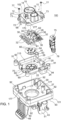
- FIG. 1 is an exploded perspective view of the electrical connector.
- an electrical connector 100 comprises a first housing member 10 that has a first base portion 12, a first tubular portion 14 (e.g., first tubular support) extending outward from the first base portion 12 and a first hollow support 16 extending outward from the first base portion 12.
- a second housing member 18 has a second base portion 20, a second tubular portion 22 (e.g., second tubular support) extending outward from the second base portion 20 and a second hollow support 24 (with recess 94, possibly with mating features on interior walls to retain a first data port and second data port) extending outward from the second base portion 20.
- the second housing member 18 engages the first housing member 10 (e.g., via snap-fit connectors 68) to form an enclosure 26.
- a substrate 28 is disposed within the enclosure 26, where the substrate 28 supports a central set of conductive members (34, 36) within the first tubular portion 14 and the second tubular portion 22.
- An interior 15 of the first tubular portion 14 contains a central set of conductive members 34, or metallic pins.
- the substrate 28 supports a peripheral set of conductive members (34, 36) within the first hollow support 16.
- An outer enclosure 27 is connected to the enclosure 26.
- the enclosure 26 or the second housing member 18 may comprise a set of sleeves 91 located about a periphery of the enclosure 27 or the second housing member 18.
- the sleeves 90 can be inserted into corresponding pockets 92 in the outer enclosure 27 to connect the outer enclosure 27 to the enclosure 26.
- a first arm 40 is pivotably attached to the outer enclosure 27 via a protruding hinge portion 83, which extends outward from the outer enclosure 27.
- the first arm 40 is pivotably attached to the enclosure 26 or the second housing member 18.
- the first arm 40 is resiliently biased inwardly toward the exterior 93 of the outer enclosure 27, or toward second base portion 20, via one or more springs 55 or other resilient members associated with a protruding hinge portion 83.
- a second arm 42 is pivotably attached to the outer enclosure 27 via a protruding hinge portion 83, which extends outward from the outer enclosure 27.
- the second arm 42 is pivotably attached to the enclosure 26 or the second housing member 18.
- the second arm 42 is spaced apart from the first arm 40.
- the second arm 42 is resiliently biased inwardly toward the exterior 93 of the outer enclosure 27, or toward the second base portion 20, via one or more springs 55 or other resilient members associated with the protruding hinge portion 83.
- the arms (40, 42) support automatic latching of the connector portion 79 (in FIG. 7 ) to a mating connector portion 63, where the latched state is illustrated in FIG. 3 .
- the first arm 40 terminates in a first tab 48; the second arm 42 terminates in a second tab 50; and a third arm 43 terminates a third tab 51.
- the first arm 40 and first tab 48 are collectively referred to as the first pawl 49; the second arm 42 and the second tab 50 are collectively referred to as the second pawl 59; the third arm 43 the third tab are collectively referred to as the third pawl 58.
- the first housing member 10, the second housing member 18 and the outer enclosure 27 can be made or formed by injection molding of plastic, a polymer, fiber-filled plastic, a fiber-filled polymer, a plastic matrix that binds of filler, or a polymer matrix that binds a filler.
- the filler or fiber may comprise glass fiber, carbon fiber, ceramic fiber, glass filler, or other filler.
- the second housing member 18 engages with and connects to the first housing member 10 via one or more snap-fit connectors 68.
- the first housing member 10 has a plurality of first snap-fit connector portions (70 or 72) and wherein the second housing member 18 has a plurality of second snap-fit connector portions (70 or 72) to interlock with corresponding ones of each other to join and secure the first housing member 10 and the second housing member 18.
- each snap-fit connector 68 comprises a connector protrusion 70 that interlocks or engages with connector slot 72 to form a snap-fit connection between the first housing member 10 and the second housing member 18 (e.g., near wings 73 and respective mating wall portion 74).
- the snap-fit connectors 68 may be replaced or supplemented by fasteners 277 that engage corresponding bores or anchors in the second housing member 18.
- the central conductive members 34 are sealed with respect to the second housing member 18 or the second base portion 20 via an elastomeric seal 64 with openings 66 to receive the central conductive members 34.
- the elastomeric seal 64 can be compressed between the substrate 28 and an annular portion or step in an interior 115 of the second housing member 18.
- the elastomeric seal 64 may be composed of silicone rubber, synthetic rubber or natural rubber, for example.
- the elastomeric seal 64 may be used alone or with additional sealant, plastic resin, polymer resin, filler, or potting compound to provide a hermetic, weather-resistant seal that is resistant to salt and fog, for instance.
- an outer enclosure 27 may be mounted on the outer surface of the enclosure 26 via interlocking of the sleeves and respective sockets 92. However, in an alternate embodiment the outer enclosure 27 may be mounted on the outer surface of the enclosure 26 via one or more fasteners 77 (e.g., that engage corresponding receptacles 177 associated with the enclosure 26).
- the outer enclosure 27 is associated with protruding supports or protruding hinges 83 that extend outward from the outer enclosure 27.
- Independent claim 1 recites an outer enclosure 27 connected to the enclosure 26, but, if the outer enclosure 27 is not used, then the protruding supports or protruding hinges 83 may extend from the second housing member 18.
- the integral protruding hinge 83 or protruding supports along with corresponding shafts 57 form pivot points 84 upon which the first arm 40, the second arm 42, and third arm 43 can rotate.
- the integral protruding hinge 83 or protruding supports have openings for receiving corresponding shafts 57.
- One or more coil springs 55 are coaxially mounted about or on respective shafts 57 to bias the first lid 44 and the second lid 46 toward or in respective closed position. In one embodiment, one or more coil springs 55 or other resilient members bias the first arm 40, the second arm 42, and the third arm 43 toward an exterior 93 of the outer enclosure 27 or second housing member 18.
- one or more coil springs 55 are coaxially mounted about or on respective shafts 57 to bias the first pawl 49, the second pawl 59, and third pawl 58 toward an exterior 93 of the outer enclosure 27.
- one end of the spring 55 is retained by a retention slot 53 in an exterior of the outer enclosure 27, whereas an opposite end of the spring is retained by a corresponding retention slot in the first pawl 49 or second pawl 59.
- the first lid 44 is associated with an arm portion 41 that terminates in a tab portion 82.
- the arm portion 41 of the first lid 44 has an opening for receiving a respective shaft 57 associated with one or more springs 55 coaxially mounted about the shaft 57.
- the second lid 46 is associated with a third arm 43 that has an opening for receiving a respective shaft 57 associated with one or more springs 55 mounted about the shaft 57.
- the first arm 40 has an opening or bore 38 for receiving a respective shaft 57 associated with one or more springs 55 coaxially mounted about the shaft 57.
- the second arm 42 has an opening or bore 38 for receiving a respective shaft 57 associated with one or more springs 55 coaxially mounted about the shaft 57.
- the first lid 44 has an arm portion 41 with an opening or bore 38 for receiving a shaft 57 or hinge pin. Opposite the arm portion 41, the first lid 44 terminates in a tab portion 82 that serves as a handle that can be manipulated by a user's hand or one or more fingers.
- the first lid 44 comprises a cap or cover that is mounted to the second housing member 18, outer enclosure 27 or base using a shaft 57 or hinge pin (e.g., composed of metal or an alloy).
- the ends of the shaft 57 are retained by push nuts or retention rings that mate with a respective groove in the shaft 57.
- a spring 55 or double torsion coil spring is used to bias the first lid 44 in a closed position over the end of the second tubular portion 22 (e.g., as shown in FIG. 5 ).
- the first lid 44 holds a seal 45 (e.g., in FIG. 4 an elastomeric substantially annular face seal 45) in a compressed state to keep dirt, debris and moisture out of the unmated connector.
- the first lid 44 can swing open or handle by a tab 82 or handle portion.
- the arm portion 41 of the first lid 44 at an end opposite of the hinged end supported by a protruding hinges 83.
- the opened first lid 44 exposes the connector portion 79 for use or connection with a mating connector portion 63.
- the connector portion 79 is illustrated as a socket that contains conductive pins 81 or substantially circular vehicle connector.
- the connector portion 79 may include optional dielectric compartments 80 or walls to separate respective conductive pins 18 from each other.
- the first arm 40 has a first notch 61 or first seating portion that presses against an annular end of the first lid 44.
- the second arm 42 has a seating portion or second notch 61 that presses against an annular end of the first lid 44.
- the connected data refers to a state when the mating connector portion 63 is plugged in or connected to the connector portion 79 as illustrated in FIG. 3 and FIG. 4 .
- the mating connector portion 63 is engaged with a socket, port or connector portion 79 in the end of the second tubular portion 22.
- the first arm 40 or first pawl 49 has a first notch 61 (or first seating surface) that engages or presses against an annular step 56 or shelf of the mating connector portion 63 to latch or lock removably the connection in place between the mating connector portion 63 and the connector portion 79.
- the second arm 42 or second pawl 59 has a second notch 61 (or second seating surface) that presses against the annular step 56 or shelf of the mating connector portion 63 to latch or lock removably the connection in place between the mating connector portion 63 and the connector portion 79.
- the notches 61 e.g., first seating portion and the second seating portion
- the notches 61 are positioned on oppositely (e.g., 180 degrees apart) with respect to a substantially annular end of the second tubular portion 22.
- the first arm 40 and the second arm 42 have notches 61 for automatically latching to (and pressing against) a first lid 44 that is hinged to the connector in a closed state and for automatically latching to (and pressing against a step in) a mating connector portion 63 in a releasable connected state.
- the notches 61 comprise seating surfaces and the notches 61 press against the first lid 44 in the closed state to form a hermetic seal 45 via an annular ring in an interior 115 of the first lid 44 that presses against an end of the second tubular portion 22.
- the notches 61 press against an end (e.g., annular end) or a step (e.g., annular step or rectangular step) in the mating connector portion 63 in a connected state to secure removably the mating connector portion 63 to the connector portion 79, where the mating connector portion 63 will automatically release from the connector portion 79 if an outward pulling force on the mating connector portion 63 exceeds a threshold level.
- an end e.g., annular end
- a step e.g., annular step or rectangular step
- a first lid 44 covers an end of the second tubular portion 22.
- the first lid 44 is hinged to the second housing member 18 and biased toward the end of second tubular portion 22.
- a second lid 46 covers a corresponding container 88 that is associated with a data port 76, where the data port 76 may comprise a first port 75, a second port 78, or both.
- the second lid 46 is hinged to the outer enclosure 27, or second housing member 18, and biased toward the container 88.
- the second lid 46 is attached to a third arm 43 that terminates in a third tab 51.
- the third arm 43 has a notch 61 for retaining a mating data port connector portion in a removably connected state when the mating connector data port connector portion is connected to the corresponding data port 76.
- the second lid 46 is opened to expose conductors of a data port, such as an Ethernet port, a Universal Serial Bus (USB) port, an ADSL (Asymmetric Digital Subscriber Line) port, or Very High Bitrate Digital Subscriber Line (VDSL) within the container 88.
- a data port such as an Ethernet port, a Universal Serial Bus (USB) port, an ADSL (Asymmetric Digital Subscriber Line) port, or Very High Bitrate Digital Subscriber Line (VDSL) within the container 88.
- the conductors of the data port 76 comprise two pins associated with two-wire Ethernet, two-wire ADSL or two-wire VDSL.
- the conductors of the data port 76 comprise four pins associated with four wire Ethernet or four-wire shielded USB port.
- the substrate 28 comprises a circuit board 30 with electrical and electronic components 32 to support communications of Controller Area Network (CAN) data messages over particular conductive members 34 of the central set and the particular conductive members 36 of the peripheral set.
- CAN Controller Area Network
- the first arm 40 terminates in a first tab 48 and the second arm 42 terminates a second tab 50, wherein the first tab 48 and the second tab 50 comprise handles to support release, by a human hand, of a mating connector portion 63 from engagement with the connector 79, or the second tubular support 22.
- the outer surfaces 52 of the first arm 40 and the first tab 48 form an angle 54 that is greater than a substantially orthogonal angle 54 to form a handle that can be pressed against readily to open a closed state or connected state of the electrical connector 100.
- the outer surfaces 52 of the second arm 42 and the second tab 50 form an angle 54 that is greater than a substantially orthogonal angle 54 to form a handle that can be pressed against readily to open a closed state or connected state of the electrical connector 100.
- the outer side 101 or implement side of the electrical connector 100 opposite the inner side 102 or tractor side, provides connector portion 79 (e.g., an integrated circular connector feature or port) with conductive members 81 for mating with mating connector portion 63 or socket with conductors that makes electrical and mechanical contact with the conductive members 81.
- the outer side 101 or implement side of the electrical connector 100 provides a plurality of integral hinges 83 that project outward from the outer side 101 to provide pivot points 84 for a first lid 44, first arm 40, a second arm 42, and a second lid 46 (or third arm 43 associated with the second lid 46).
- the first arm 40, the second arm 42 and the third arm 43 may terminate in respective tabs (48, 50, 82) that can provide handles for a user to operate to connect and disconnect a mating connector portion 63 (e.g., mating plug or socket) to the connector portion 79 of the electrical connector 100.
- a mating connector portion 63 e.g., mating plug or socket
- pawl 49, 59
- the arms or pawls (49, 59) are supported by a shaft 57 or hinge pin that is mounted between protruding hinges 83 that extend outward from the surface of the second housing member 18 or outer enclosure 27, where the torsion spring 55 biases the arms or pawls (49, 59) toward the second housing member 18 or outer enclosure 27.
- the electrical connector may have standard footprint to match the ISO 11783-2 (ISOBUS) four bolt mounting footprint of openings 60 on a vehicle.
- the pawls (49, 59) are arranged with the hook portions, seating portions, or notches 61 facing inward towards the second tubular portion 22 or connector portion 79 (e.g., substantially circular vehicle connector).
- the pawls (49, 59) are spring-loaded (e.g., by springs 55) or resiliently biased to latch or close towards the end of the second tubular portion 22 or connector portion 79 (e.g., implement connector portion). Both pawls (49, 59) can rotate or swing respective handle portions in a pawl arc in a pawl plane that is generally perpendicular to a lid arc or lid plane of the first lid 44.
- each pawl (49, 59) in the inward pawl arc is limited by a stop or limit of the pawl (49, 59) or its arm at or near the respective hinge 83, such as a bottom edge of the pawl (49, 59) or its respective arm (40, 42) that rests against an exterior 93 of the outer enclosure 27. Accordingly, both pawls (49, 59) are always separated by at least a minimum distance (e.g., minimum lateral distance proportional to the dimensions or width of the mating connector portion 63) between hook portions, seating portions or notches 61, such that the mating connector portion 63 can be readily, removably connected or disconnected.
- a minimum distance e.g., minimum lateral distance proportional to the dimensions or width of the mating connector portion 63
- the electrical connector 100 has several states, such as a normally closed and sealed state for the first lid 44, the second lid 46, or both.
- the normally closed and sealed state refers to a state in which the mating connector portion 63 is disconnected from the connector portion 79 (e.g., substantially circular vehicle connector). If the mating connector portion 63 is disconnected or if the connector portion 79 is not in use, then the first lid 44 will be closed covering and sealing hermetically the connector opening of the connector portion 79. Similarly, if the mating connector is disconnected from the data port 76, such as an Ethernet port or USB port, then the second lid 46 will be closed covering and sealing hermetically the connector opening or container 88 to prevent the ingress of moisture, dirt, debris and contaminants.
- the data port 76 such as an Ethernet port or USB port
- the first lid 44 is a cap or cover for protecting the connector 79 from the ingress of dirt, debris, contaminants, salt, corrosive chemicals, or moisture that might otherwise damage (e.g., corrode) the conductor members 81 or interfere with a reliable electrical connection associated with the electrical connector 100 and a corresponding mating connector portion 63. If the first lid 44 is closed, then the first pawl 49 or first arm 40 and the second pawl 59 or second arm 42 latch or resiliently bias the first lid 44 in the closed position, against an annular step 56 (in FIG. 4 ), by the notches 61, seating portions or hook features. If the second lid 46 is closed, then the third arm 43 or third pawl latch or resiliently bias the second lid 46 in the closed position, against the container 88, by a notch 61, seating portion or hook feature.
- the arms (40, 42) will move outward and unlatch allowing the first lid 44 to be opened. If the first lid 44 is opened sufficiently, then the user can manually insert of the mating connector portion 63 portion of the electrical connector 100 into the connector portion 79 to form a reliable electrical and mechanical connection between the vehicle and an external cable 47 and connector portion 79 (e.g., associated with an implement, such as a towed implement).
- the mating connector portion 63 comprises an implement harness connector.
- the pawls (49, 59) will open to receive the mating connector portion 63. If the mating connector portion 63 (e.g., implement harness connector) pushes past the pawls (49, 59) to a fully seated condition, then both pawls (49, 59) will return to a rest position which that positively retains or latches the mating connector portion 63 to the electrical connector 100 in the mated and sealed position, which can also be referred to as a connected state.
- the mating connector portion 63 e.g., implement harness connector
- the mating connector portion 63 e.g., mated implement harness connector
- the user presses e.g., bumps
- the pawls (49, 59) will move outward and unlatch allowing or handle portion the mating connector portion 63 to disconnect from the electrical connector 100 or second tubular portion 22.
- the mating connector portion 63 e.g., implement harness connecter
- the first lid 44 or cover will automatically push past the pawls (49, 59) to close over top of the end of the second tubular portion 22 or the vehicle connector opening of connector portion 79. If the first lid 44 is closed completely, then both pawls (49, 59) will return to a rest position which positively retains or latches the first lid 44 in the closed and sealed position.
- the mating connector portion 63 portion e.g., the mated implement harness
- the pawls (49, 59) will open releasing the mating connector portion 63 (e.g., implement harness connector) without damage to the electrical connector or the mating connector portion 63, or the mated implement cable 47 or wire harness.
- the electrical connector 100 of the disclosure features a robust spring-loaded hinge pin design (e.g., shaft 57 and torsion springs 55) for connector's moving parts to foster reliability and longevity.
- the electrical connector 100 is well suited for providing automatic latching of one or more lids and automatic latching between the electrical connector and mating connector portion (e.g., 63), such as an implement harness connector or data port connector. Accordingly, the automatic latching of lids protects the conductive members from damage, corrosion and the ingress of dirt and debris that might otherwise interfere with a reliable electrical connection between the electrical connector and mating connector portion.
- the electrical connector provides additional space that supports a high speed data connection, such as Ethernet, two-wire Ethernet, four-wire Ethernet or USB.
Landscapes
- Engineering & Computer Science (AREA)
- Transportation (AREA)
- Mechanical Engineering (AREA)
- Connector Housings Or Holding Contact Members (AREA)
Claims (16)
- Elektrischer Steckverbinder (100), der Folgendes aufweist:ein erstes Gehäuseelement (10) mit einem ersten Basisteil (12), einem ersten rohrförmigen Teil (14), der sich von dem ersten Basisteil nach außen erstreckt, und einer ersten hohlen Stütze (16), die sich von dem ersten Basisteil nach außen erstreckt;ein zweites Gehäuseelement (18) mit einem zweiten Basisteil (20), einem zweiten rohrförmigen Teil (22), der sich von dem zweiten Basisteil nach außen erstreckt, und einer zweiten hohlen Stütze (24), die sich von dem zweiten Basisteil nach außen erstreckt; wobei das zweite Gehäuseelement mit dem ersten Gehäuseelement, eine Umhausung (26) bildend, in Eingriff ist;in der Umhausung (26) einen Träger (28), der einen zentralen Satz leitfähiger Elemente (34) in dem zweiten rohrförmigen Teil trägt, wobei der Träger einen peripheren Satz leitfähiger Elemente (36) in der ersten hohlen Stütze trägt;eine äußere Umhausung (27), die mit der Umhausung (26) verbunden ist;einen ersten Arm (40), der schwenkbar an einem ersten Drehpunkt (84) entweder an der äußeren Umhausung (27) oder der Umhausung (26) des elektrischen Steckverbinders angebracht ist; undeinen zweiten Arm (42), der schwenkbar an einem zweiten Drehpunkt (84) entweder an der äußeren Umhausung (27) oder der Umhausung (26) des elektrischen Steckverbinders verbunden ist und von dem ersten Arm beabstandet ist, wobei der zweite Drehpunkt von dem ersten Drehpunkt verschieden ist, dadurch gekennzeichnet, dassder erste Arm sich nach außen von dem zweiten Basisteil (20) des zweiten Gehäuseelements (18) und in Richtung auf ihn federnd einwärts vorgespannt erstreckt;und der zweite Arm sich nach außen von dem zweiten Basisteil (20) des zweiten Gehäuseelements (18) und in Richtung auf ihn federnd einwärts vorgespannt erstreckt.
- Elektrischer Steckverbinder nach Anspruch 1, wobei der erste Arm (40) über einen vorstehenden Gelenkteil (83), der sich von der äußere Umhausung (27) nach außen erstreckt, schwenkbar an der äußere Umhausung (27) angebracht ist und wobei der zweite Arm (42) über einen weiteren vorstehenden Gelenkteil (83), der sich ebenfalls von der äußere Umhausung (27) nach außen erstreckt, schwenkbar an der äußere Umhausung (27) angebracht ist.
- Elektrischer Steckverbinder nach Anspruch 1, der ferner einen ersten Deckel (44) aufweist, der an den Steckverbinder angelenkt ist, wobei der erste Arm und der zweite Arm jeweilige Aussparungen (61) zum automatischen Verriegeln am ersten Deckel (44) in einem geschlossenen Zustand und zum automatischen Verriegeln mit einem Gegen-Steckverbinderteil (63) in einem lösbaren verbundenen Zustand haben.
- Elektrischer Steckverbinder nach Anspruch 3, wobei:
die Aussparungen (61) im geschlossenen Zustand gegen den ersten Deckel (44) drücken, um eine hermetische Dichtung über einen Ring mit kreisförmigem Querschnitt (115) in einem Inneren des ersten Deckels zu bilden, der gegen ein Ende des zweiten rohrförmigen Teils drückt. - Elektrischer Steckverbinder nach Anspruch 3 oder Anspruch 4, der ferner ein Gegen-Steckverbinderteil (63) aufweist, das mit dem elektrischen Steckverbinder verbunden ist, wobei der Gegen-Steckverbinderteil eine auswärts angeordnete Stufe aufweist, gegen die die Aussparungen (61) des ersten und des zweiten Arms drücken, um den Gegen-Steckverbinderteil abnehmbar an dem Steckverbinder zu befestigen, wobei sich der Gegen-Steckverbinderteil automatisch vom Steckverbinder löst, wenn eine nach außen gerichtete Zugkraft auf den Gegen-Steckverbinderteil ein Schwellenniveau übersteigt.
- Elektrischer Steckverbinder nach Anspruch 1, wobei das zweite Gehäuseelement über einen Schnappverbinder (68) mit dem ersten Gehäuseelement in Eingriff kommt und verbunden wird und wobei wahlweise:
das erste Gehäuseelement mehrere erste Schnappverbinderteile (72) hat und das zweite Gehäuseelement mehrere zweite Schnappverbinderteile (70) zum Verriegeln mit entsprechenden der mehreren ersten Schnappverbinderteile hat, um das erste Gehäuseelement und das zweite Gehäuseelement zusammenzufügen und aneinander zu befestigen. - Elektrischer Steckverbinder nach Anspruch 1, der eine elastomere Dichtung (64) mit Öffnungen zum Aufnehmen der zentralen leitfähigen Elemente (34) zwischen dem Träger und dem zweiten Gehäuseelement aufweist,
wobei, wahlweise, die elastomere Dichtung zwischen dem Träger und einem ringförmigen Teil (115) in einem Inneren des zweiten Gehäuseelements zusammengedrückt wird. - Elektrischer Steckverbinder nach Anspruch 1, der ferner Folgendes aufweist:
einen ersten Deckel (44) zum Bedecken eines Endes des zweiten rohrförmigen Teils, wobei der erste Deckel (44) an dem zweiten Gehäuseelement angelenkt ist und in Richtung auf das Ende des zweiten rohrförmigen Teils vorgespannt ist. - Elektrischer Steckverbinder nach Anspruch 1, der ferner Folgendes aufweist:einen zweiten Deckel (46) zum Bedecken eines entsprechenden Behälters, wobei der zweite Deckel an das zweite Gehäuseelement angelenkt ist und in Richtung auf die zweite hohle Stütze vorgespannt ist, wobei der zweite Deckel an einem dritten Arm (43) angebracht ist, der in einer Zunge (51) endet,wobei der dritte Arm wahlweise eine Aussparung (61) hat zum Festhalten eines Gegen-Steckverbinderteils in einem abnehmbar verbundenen Zustand, wenn der Gegen-Steckverbinderteil mit dem Steckverbinderteil verbunden ist.
- Elektrischer Steckverbinder nach Anspruch 9, wobei der zweite Deckel (43) geöffnet wird, um Leiter eines Datenanschlusses in dem Behälter freizulegen.
- Elektrischer Steckverbinder nach Anspruch 10, wobei die Steckverbinder zwei Zweidraht-Ethernet zugeordnete Stifte umfassen oder die Steckverbinder vier Vierdraht-Ethernet zugeordnete Stifte umfassen.
- Elektrischer Steckverbinder nach Anspruch 1, wobei der Träger eine Leiterplatte (30) mit elektrischen und elektronischen Komponenten zum Unterstützen der Kommunikation der Controller Area Network-, CAN, -Datennachrichten über besondere leitfähige Elemente des zentralen Satzes und der besonderen leitfähigen Elemente des peripheren Satzes aufweist.
- Elektrischer Steckverbinder nach Anspruch 1, wobei der erste Arm in einer ersten Zunge (48) endet und der zweite Arm in einer zweiten Zunge (50) endet, wobei die erste Zunge und die zweite Zunge das Lösen eines Gegen-Steckverbinderteils (63) aus dem Eingriff mit dem ersten rohrförmigen Teil oder einem Steckverbinderteil durch eine menschliche Hand unterstützen und wobei, wahlweise:
Außenflächen des ersten Arms und der ersten Zunge einen Winkel bilden, der größer als ein im Wesentlichen orthogonaler Winkel ist, und wobei Außenflächen des zweiten Arms und der zweiten Zunge einen Winkel bilden, der größer als ein im Wesentlichen orthogonaler Winkel ist. - Elektrischer Steckverbinder nach Anspruch 1, wobei der erste Arm einen ersten Sitzflächenteil hat, der gegen ein ringförmiges Ende des zweiten rohrförmigen Teils drückt, wenn ein Gegen-Steckverbinderteil mit einem Verbinderteil im Ende des zweiten rohrförmigen Teils in Eingriff ist, und wobei der zweite Arm einen zweiten Sitzflächenteil hat, der gegen das ringförmige Ende des zweiten rohrförmigen Teil drückt, wenn der Gegen-Steckverbinderteil mit einem Steckverbinderteil in einem Ende des zweiten rohrförmigen Teils in Eingriff kommt.
- Elektrischer Steckverbinder nach Anspruch 14, wobei der erste Sitzflächenteil und der zweite Sitzflächenteil am ringförmigen Ende des zweiten rohrförmigen Teils einander entgegengesetzt positioniert sind.
- Elektrischer Steckverbinder nach Anspruch 1, wobei die äußere Umhausung um ihren Umfang einen Satz Aufnahmen aufweist und wobei die äußere Umhausung Hülsen hat, die sich mit den entsprechenden Aufnahmen verriegeln.
Applications Claiming Priority (1)
| Application Number | Priority Date | Filing Date | Title |
|---|---|---|---|
| US15/900,435 US10326236B1 (en) | 2018-02-20 | 2018-02-20 | Electrical connector with automatic latching |
Publications (2)
| Publication Number | Publication Date |
|---|---|
| EP3528347A1 EP3528347A1 (de) | 2019-08-21 |
| EP3528347B1 true EP3528347B1 (de) | 2024-06-26 |
Family
ID=65529452
Family Applications (1)
| Application Number | Title | Priority Date | Filing Date |
|---|---|---|---|
| EP19158406.9A Active EP3528347B1 (de) | 2018-02-20 | 2019-02-20 | Elektrischer steckverbinder mit automatischer verriegelung |
Country Status (2)
| Country | Link |
|---|---|
| US (2) | US10326236B1 (de) |
| EP (1) | EP3528347B1 (de) |
Families Citing this family (10)
| Publication number | Priority date | Publication date | Assignee | Title |
|---|---|---|---|---|
| US10326236B1 (en) * | 2018-02-20 | 2019-06-18 | Deere & Company | Electrical connector with automatic latching |
| JP7084789B2 (ja) * | 2018-06-14 | 2022-06-15 | 株式会社Subaru | 充電用ソケット及び充電用ソケットのブラケット |
| DE102018121680B3 (de) * | 2018-09-05 | 2019-12-19 | Lufthansa Technik Aktiengesellschaft | Steckverbindungsdose und Passagierversorgungsmodul |
| BE1026857B1 (de) * | 2018-12-10 | 2020-07-13 | Phoenix Contact E Mobility Gmbh | Steckverbinderteil mit einer Leiterplatte |
| US10923869B2 (en) * | 2019-06-10 | 2021-02-16 | Toyota Motor Engineering & Manufacturing North America, Inc. | Vehicle harness connector interface assemblies |
| CN111786197B (zh) * | 2020-08-07 | 2025-03-18 | 惠州市金富永五金制品有限公司 | 一种防水pin针连接器 |
| CN214625556U (zh) * | 2021-05-07 | 2021-11-05 | 泰科电子(上海)有限公司 | 充电座 |
| WO2023028370A1 (en) * | 2021-08-27 | 2023-03-02 | Lippert Components, Inc. | Power cord slide connector coupling and method of connecting |
| JP7638845B2 (ja) * | 2021-10-06 | 2025-03-04 | 日本航空電子工業株式会社 | コネクタ装置 |
| US11735863B2 (en) | 2021-10-19 | 2023-08-22 | Deere & Company | Electrical connector with automatic latching and slidable lock |
Citations (2)
| Publication number | Priority date | Publication date | Assignee | Title |
|---|---|---|---|---|
| DE202009002880U1 (de) * | 2009-03-03 | 2010-07-22 | Erich Jaeger Gmbh & Co. Kg | Steckdose |
| EP1492203B1 (de) * | 2003-06-23 | 2012-03-21 | Deere & Company | Verbindungseinrichtung |
Family Cites Families (35)
| Publication number | Priority date | Publication date | Assignee | Title |
|---|---|---|---|---|
| US2496208A (en) * | 1946-09-16 | 1950-01-31 | Pollak Corp Joseph | Electrical connector |
| SE415511B (sv) * | 1979-01-08 | 1980-10-06 | Volvo Ab | Elektriskt anslutningsdon |
| DE9205811U1 (de) | 1992-04-30 | 1992-08-13 | Erich Jaeger GmbH & Co KG, 6380 Bad Homburg | Steckverbindung, insbesondere für den elektrischen Anschluß von Anhängerfahrzeugen |
| US5302141A (en) * | 1992-11-23 | 1994-04-12 | Cole Hersee Company | Compatible trailer connection |
| US5785532A (en) * | 1993-06-09 | 1998-07-28 | United Technologies Automotive, Inc. | Power distribution box and system |
| JP2739627B2 (ja) * | 1993-12-20 | 1998-04-15 | 矢崎総業株式会社 | コネクタハウジング結合機構 |
| FR2733635B1 (fr) * | 1995-04-25 | 1997-07-25 | Carrier Kheops Bac | Connecteur electrique a poignee d'actionnement perfectionne |
| US5873744A (en) * | 1997-02-18 | 1999-02-23 | Ramos, Jr.; Phillip M. | Electrical connector assembly |
| US5951309A (en) * | 1998-03-02 | 1999-09-14 | Hubbell Incorporated | Receptacle assembly having position retention tabs |
| US6054779A (en) * | 1998-04-14 | 2000-04-25 | Strick Corporation | Electrical power connector for tandem trailers |
| MXPA02009235A (es) * | 2000-03-22 | 2004-04-05 | R A Phillips Ind Inc | Ensamble de tapon y enchufe electricos autosellante para camiones. |
| US6450833B1 (en) * | 2000-08-25 | 2002-09-17 | Wabash Technology Corporation | Seven-way trailer connector |
| US6554626B2 (en) * | 2001-04-17 | 2003-04-29 | Philatron International | Electrical receptacle assembly |
| US6840782B1 (en) | 2004-02-26 | 2005-01-11 | Aaron M. Borden | Dual-sectioned grounding bushing assembly |
| DE202005001568U1 (de) | 2005-01-31 | 2005-03-31 | Jaeger Erich Gmbh & Co Kg | Steckdose |
| CA2540612A1 (en) * | 2005-03-24 | 2006-09-24 | Bld Products, Ltd. | Electrical connector assembly |
| US7491065B2 (en) * | 2006-11-14 | 2009-02-17 | Karl Wagner | Surface mount trailer electrical connector |
| WO2008116224A1 (en) * | 2007-03-22 | 2008-09-25 | Stoneridge Control Devices, Inc. | Trailer tow connector assembly |
| US7643271B2 (en) * | 2008-02-04 | 2010-01-05 | R.A. Phillips Industries, Inc. | Electrical junction box for tractor trailer |
| US9415730B2 (en) * | 2008-04-23 | 2016-08-16 | Littlefuse, Inc. | Flexible power distribution module cover assembly |
| US8241053B2 (en) * | 2009-09-10 | 2012-08-14 | Vocollect, Inc. | Electrical cable with strength member |
| US8167639B2 (en) * | 2010-02-02 | 2012-05-01 | Tyco Electronics Corporation | Coaxial latching connector assembly |
| US8251732B2 (en) * | 2010-06-28 | 2012-08-28 | Maxi-Seal Harness Systems Inc. | Power input electrical connector |
| US8888515B2 (en) * | 2010-08-11 | 2014-11-18 | Erich Jaeger Gmbh + Co. Kg | Socket |
| US8376758B2 (en) * | 2010-09-14 | 2013-02-19 | Tramec, L.L.C. | Receptacle with printed circuit board |
| US8540527B2 (en) * | 2011-02-07 | 2013-09-24 | R.A. Phillips Industries, Inc. | Jumper cable plug with moisture resistant seal |
| US8192216B1 (en) * | 2011-02-07 | 2012-06-05 | R.A. Phillips Industries, Inc. | Electrical connector with moisture resistant seal |
| ES2685676T3 (es) | 2012-02-07 | 2018-10-10 | R.A. Phillips Industries, Inc. | Enchufe de cable de conexión con junta resistente a la humedad |
| DE102012007911B4 (de) * | 2012-04-20 | 2014-07-17 | Schaltbau Gmbh | Elektrische Steckverbindung |
| US8939785B2 (en) * | 2012-10-04 | 2015-01-27 | Gt Contact Co., Ltd. | Cable connector with spring-loaded plunger and assembly thereof |
| ITTO20130519A1 (it) * | 2013-06-25 | 2014-12-26 | Menber S Spa | Presa con blocco coperchio |
| US9543719B2 (en) | 2014-10-09 | 2017-01-10 | Deere & Company | Electrical connector for a vehicle |
| US9496639B2 (en) * | 2015-03-13 | 2016-11-15 | Grote Industries, Inc. | Electrical connectors for vehicles |
| JP6295239B2 (ja) * | 2015-10-26 | 2018-03-14 | 矢崎総業株式会社 | 電子制御ユニットのコネクタ接続構造及び電子制御ユニット |
| US10326236B1 (en) * | 2018-02-20 | 2019-06-18 | Deere & Company | Electrical connector with automatic latching |
-
2018
- 2018-02-20 US US15/900,435 patent/US10326236B1/en active Active
-
2019
- 2019-02-18 US US16/278,448 patent/US10707611B2/en active Active
- 2019-02-20 EP EP19158406.9A patent/EP3528347B1/de active Active
Patent Citations (2)
| Publication number | Priority date | Publication date | Assignee | Title |
|---|---|---|---|---|
| EP1492203B1 (de) * | 2003-06-23 | 2012-03-21 | Deere & Company | Verbindungseinrichtung |
| DE202009002880U1 (de) * | 2009-03-03 | 2010-07-22 | Erich Jaeger Gmbh & Co. Kg | Steckdose |
Also Published As
| Publication number | Publication date |
|---|---|
| EP3528347A1 (de) | 2019-08-21 |
| US10707611B2 (en) | 2020-07-07 |
| US20190260161A1 (en) | 2019-08-22 |
| US10326236B1 (en) | 2019-06-18 |
Similar Documents
| Publication | Publication Date | Title |
|---|---|---|
| EP3528347B1 (de) | Elektrischer steckverbinder mit automatischer verriegelung | |
| US7025636B2 (en) | Adaptor for making broken connectors serviceable | |
| JP2762347B2 (ja) | 端子位置保証手段を有するフード付き電気コネクタ | |
| US5954536A (en) | Connector for flat flexible circuitry | |
| CN212392437U (zh) | 连接器 | |
| US4345813A (en) | Keyable connector-header assemblies for multiple conductor cables | |
| CN101133524A (zh) | 连接器用护罩以及连接器组装体 | |
| EP2412062B1 (de) | Verbinderanordnung mit einer verriegelung | |
| WO2007130291A2 (en) | Computer interface jack | |
| EP1233477B1 (de) | Wasserdichter Verbinder für flexibles Flachkabel | |
| EP4170828A1 (de) | Elektrischer verbinder mit automatischer verriegelung und verschiebbarer verriegelung | |
| US6827594B1 (en) | Connector assembly | |
| US5425654A (en) | Electrical connector assembly with cam lever lock mechanism | |
| CN101971434A (zh) | 连接器护盖 | |
| EP2240983B1 (de) | Verriegelnde elektrische aufnahme | |
| US7182626B2 (en) | Electrical connector with improved latch means | |
| US7258556B1 (en) | Spring loaded cover for electrical connector | |
| US9184538B1 (en) | Replacement adaptor for broken clip on cable connector | |
| WO2007097746A1 (en) | Adapter for making broken connectors serviceable | |
| GB2393046A (en) | Connectors and assemblies | |
| GB2191640A (en) | A multi-core flat electrical or optical fibre cable connector | |
| CN1732599A (zh) | 用于带母线的照明系统中的电插座的插头 |
Legal Events
| Date | Code | Title | Description |
|---|---|---|---|
| PUAI | Public reference made under article 153(3) epc to a published international application that has entered the european phase |
Free format text: ORIGINAL CODE: 0009012 |
|
| STAA | Information on the status of an ep patent application or granted ep patent |
Free format text: STATUS: THE APPLICATION HAS BEEN PUBLISHED |
|
| AK | Designated contracting states |
Kind code of ref document: A1 Designated state(s): AL AT BE BG CH CY CZ DE DK EE ES FI FR GB GR HR HU IE IS IT LI LT LU LV MC MK MT NL NO PL PT RO RS SE SI SK SM TR |
|
| AX | Request for extension of the european patent |
Extension state: BA ME |
|
| STAA | Information on the status of an ep patent application or granted ep patent |
Free format text: STATUS: REQUEST FOR EXAMINATION WAS MADE |
|
| 17P | Request for examination filed |
Effective date: 20200221 |
|
| RBV | Designated contracting states (corrected) |
Designated state(s): AL AT BE BG CH CY CZ DE DK EE ES FI FR GB GR HR HU IE IS IT LI LT LU LV MC MK MT NL NO PL PT RO RS SE SI SK SM TR |
|
| STAA | Information on the status of an ep patent application or granted ep patent |
Free format text: STATUS: EXAMINATION IS IN PROGRESS |
|
| 17Q | First examination report despatched |
Effective date: 20200715 |
|
| GRAP | Despatch of communication of intention to grant a patent |
Free format text: ORIGINAL CODE: EPIDOSNIGR1 |
|
| STAA | Information on the status of an ep patent application or granted ep patent |
Free format text: STATUS: GRANT OF PATENT IS INTENDED |
|
| INTG | Intention to grant announced |
Effective date: 20240305 |
|
| GRAS | Grant fee paid |
Free format text: ORIGINAL CODE: EPIDOSNIGR3 |
|
| GRAA | (expected) grant |
Free format text: ORIGINAL CODE: 0009210 |
|
| STAA | Information on the status of an ep patent application or granted ep patent |
Free format text: STATUS: THE PATENT HAS BEEN GRANTED |
|
| AK | Designated contracting states |
Kind code of ref document: B1 Designated state(s): AL AT BE BG CH CY CZ DE DK EE ES FI FR GB GR HR HU IE IS IT LI LT LU LV MC MK MT NL NO PL PT RO RS SE SI SK SM TR |
|
| REG | Reference to a national code |
Ref country code: GB Ref legal event code: FG4D |
|
| REG | Reference to a national code |
Ref country code: CH Ref legal event code: EP |
|
| REG | Reference to a national code |
Ref country code: DE Ref legal event code: R096 Ref document number: 602019054069 Country of ref document: DE |
|
| PG25 | Lapsed in a contracting state [announced via postgrant information from national office to epo] |
Ref country code: BG Free format text: LAPSE BECAUSE OF FAILURE TO SUBMIT A TRANSLATION OF THE DESCRIPTION OR TO PAY THE FEE WITHIN THE PRESCRIBED TIME-LIMIT Effective date: 20240626 |
|
| PG25 | Lapsed in a contracting state [announced via postgrant information from national office to epo] |
Ref country code: HR Free format text: LAPSE BECAUSE OF FAILURE TO SUBMIT A TRANSLATION OF THE DESCRIPTION OR TO PAY THE FEE WITHIN THE PRESCRIBED TIME-LIMIT Effective date: 20240626 Ref country code: FI Free format text: LAPSE BECAUSE OF FAILURE TO SUBMIT A TRANSLATION OF THE DESCRIPTION OR TO PAY THE FEE WITHIN THE PRESCRIBED TIME-LIMIT Effective date: 20240626 |
|
| REG | Reference to a national code |
Ref country code: LT Ref legal event code: MG9D |
|
| PG25 | Lapsed in a contracting state [announced via postgrant information from national office to epo] |
Ref country code: GR Free format text: LAPSE BECAUSE OF FAILURE TO SUBMIT A TRANSLATION OF THE DESCRIPTION OR TO PAY THE FEE WITHIN THE PRESCRIBED TIME-LIMIT Effective date: 20240927 |
|
| PG25 | Lapsed in a contracting state [announced via postgrant information from national office to epo] |
Ref country code: LV Free format text: LAPSE BECAUSE OF FAILURE TO SUBMIT A TRANSLATION OF THE DESCRIPTION OR TO PAY THE FEE WITHIN THE PRESCRIBED TIME-LIMIT Effective date: 20240626 |
|
| REG | Reference to a national code |
Ref country code: NL Ref legal event code: MP Effective date: 20240626 |
|
| PG25 | Lapsed in a contracting state [announced via postgrant information from national office to epo] |
Ref country code: NO Free format text: LAPSE BECAUSE OF FAILURE TO SUBMIT A TRANSLATION OF THE DESCRIPTION OR TO PAY THE FEE WITHIN THE PRESCRIBED TIME-LIMIT Effective date: 20240926 Ref country code: LV Free format text: LAPSE BECAUSE OF FAILURE TO SUBMIT A TRANSLATION OF THE DESCRIPTION OR TO PAY THE FEE WITHIN THE PRESCRIBED TIME-LIMIT Effective date: 20240626 Ref country code: HR Free format text: LAPSE BECAUSE OF FAILURE TO SUBMIT A TRANSLATION OF THE DESCRIPTION OR TO PAY THE FEE WITHIN THE PRESCRIBED TIME-LIMIT Effective date: 20240626 Ref country code: GR Free format text: LAPSE BECAUSE OF FAILURE TO SUBMIT A TRANSLATION OF THE DESCRIPTION OR TO PAY THE FEE WITHIN THE PRESCRIBED TIME-LIMIT Effective date: 20240927 Ref country code: FI Free format text: LAPSE BECAUSE OF FAILURE TO SUBMIT A TRANSLATION OF THE DESCRIPTION OR TO PAY THE FEE WITHIN THE PRESCRIBED TIME-LIMIT Effective date: 20240626 Ref country code: BG Free format text: LAPSE BECAUSE OF FAILURE TO SUBMIT A TRANSLATION OF THE DESCRIPTION OR TO PAY THE FEE WITHIN THE PRESCRIBED TIME-LIMIT Effective date: 20240626 Ref country code: RS Free format text: LAPSE BECAUSE OF FAILURE TO SUBMIT A TRANSLATION OF THE DESCRIPTION OR TO PAY THE FEE WITHIN THE PRESCRIBED TIME-LIMIT Effective date: 20240926 |
|
| PG25 | Lapsed in a contracting state [announced via postgrant information from national office to epo] |
Ref country code: NL Free format text: LAPSE BECAUSE OF FAILURE TO SUBMIT A TRANSLATION OF THE DESCRIPTION OR TO PAY THE FEE WITHIN THE PRESCRIBED TIME-LIMIT Effective date: 20240626 |
|
| REG | Reference to a national code |
Ref country code: AT Ref legal event code: MK05 Ref document number: 1698503 Country of ref document: AT Kind code of ref document: T Effective date: 20240626 |
|
| PG25 | Lapsed in a contracting state [announced via postgrant information from national office to epo] |
Ref country code: NL Free format text: LAPSE BECAUSE OF FAILURE TO SUBMIT A TRANSLATION OF THE DESCRIPTION OR TO PAY THE FEE WITHIN THE PRESCRIBED TIME-LIMIT Effective date: 20240626 |
|
| PG25 | Lapsed in a contracting state [announced via postgrant information from national office to epo] |
Ref country code: PT Free format text: LAPSE BECAUSE OF FAILURE TO SUBMIT A TRANSLATION OF THE DESCRIPTION OR TO PAY THE FEE WITHIN THE PRESCRIBED TIME-LIMIT Effective date: 20241028 |
|
| PG25 | Lapsed in a contracting state [announced via postgrant information from national office to epo] |
Ref country code: PT Free format text: LAPSE BECAUSE OF FAILURE TO SUBMIT A TRANSLATION OF THE DESCRIPTION OR TO PAY THE FEE WITHIN THE PRESCRIBED TIME-LIMIT Effective date: 20241028 |
|
| PG25 | Lapsed in a contracting state [announced via postgrant information from national office to epo] |
Ref country code: PL Free format text: LAPSE BECAUSE OF FAILURE TO SUBMIT A TRANSLATION OF THE DESCRIPTION OR TO PAY THE FEE WITHIN THE PRESCRIBED TIME-LIMIT Effective date: 20240626 |
|
| PG25 | Lapsed in a contracting state [announced via postgrant information from national office to epo] |
Ref country code: EE Free format text: LAPSE BECAUSE OF FAILURE TO SUBMIT A TRANSLATION OF THE DESCRIPTION OR TO PAY THE FEE WITHIN THE PRESCRIBED TIME-LIMIT Effective date: 20240626 |
|
| PG25 | Lapsed in a contracting state [announced via postgrant information from national office to epo] |
Ref country code: AT Free format text: LAPSE BECAUSE OF FAILURE TO SUBMIT A TRANSLATION OF THE DESCRIPTION OR TO PAY THE FEE WITHIN THE PRESCRIBED TIME-LIMIT Effective date: 20240626 Ref country code: IS Free format text: LAPSE BECAUSE OF FAILURE TO SUBMIT A TRANSLATION OF THE DESCRIPTION OR TO PAY THE FEE WITHIN THE PRESCRIBED TIME-LIMIT Effective date: 20241026 |
|
| PG25 | Lapsed in a contracting state [announced via postgrant information from national office to epo] |
Ref country code: CZ Free format text: LAPSE BECAUSE OF FAILURE TO SUBMIT A TRANSLATION OF THE DESCRIPTION OR TO PAY THE FEE WITHIN THE PRESCRIBED TIME-LIMIT Effective date: 20240626 |
|
| PG25 | Lapsed in a contracting state [announced via postgrant information from national office to epo] |
Ref country code: RO Free format text: LAPSE BECAUSE OF FAILURE TO SUBMIT A TRANSLATION OF THE DESCRIPTION OR TO PAY THE FEE WITHIN THE PRESCRIBED TIME-LIMIT Effective date: 20240626 Ref country code: SK Free format text: LAPSE BECAUSE OF FAILURE TO SUBMIT A TRANSLATION OF THE DESCRIPTION OR TO PAY THE FEE WITHIN THE PRESCRIBED TIME-LIMIT Effective date: 20240626 |
|
| PG25 | Lapsed in a contracting state [announced via postgrant information from national office to epo] |
Ref country code: ES Free format text: LAPSE BECAUSE OF FAILURE TO SUBMIT A TRANSLATION OF THE DESCRIPTION OR TO PAY THE FEE WITHIN THE PRESCRIBED TIME-LIMIT Effective date: 20240626 Ref country code: SM Free format text: LAPSE BECAUSE OF FAILURE TO SUBMIT A TRANSLATION OF THE DESCRIPTION OR TO PAY THE FEE WITHIN THE PRESCRIBED TIME-LIMIT Effective date: 20240626 |
|
| PG25 | Lapsed in a contracting state [announced via postgrant information from national office to epo] |
Ref country code: SM Free format text: LAPSE BECAUSE OF FAILURE TO SUBMIT A TRANSLATION OF THE DESCRIPTION OR TO PAY THE FEE WITHIN THE PRESCRIBED TIME-LIMIT Effective date: 20240626 Ref country code: SK Free format text: LAPSE BECAUSE OF FAILURE TO SUBMIT A TRANSLATION OF THE DESCRIPTION OR TO PAY THE FEE WITHIN THE PRESCRIBED TIME-LIMIT Effective date: 20240626 Ref country code: RO Free format text: LAPSE BECAUSE OF FAILURE TO SUBMIT A TRANSLATION OF THE DESCRIPTION OR TO PAY THE FEE WITHIN THE PRESCRIBED TIME-LIMIT Effective date: 20240626 Ref country code: PL Free format text: LAPSE BECAUSE OF FAILURE TO SUBMIT A TRANSLATION OF THE DESCRIPTION OR TO PAY THE FEE WITHIN THE PRESCRIBED TIME-LIMIT Effective date: 20240626 Ref country code: IS Free format text: LAPSE BECAUSE OF FAILURE TO SUBMIT A TRANSLATION OF THE DESCRIPTION OR TO PAY THE FEE WITHIN THE PRESCRIBED TIME-LIMIT Effective date: 20241026 Ref country code: ES Free format text: LAPSE BECAUSE OF FAILURE TO SUBMIT A TRANSLATION OF THE DESCRIPTION OR TO PAY THE FEE WITHIN THE PRESCRIBED TIME-LIMIT Effective date: 20240626 Ref country code: EE Free format text: LAPSE BECAUSE OF FAILURE TO SUBMIT A TRANSLATION OF THE DESCRIPTION OR TO PAY THE FEE WITHIN THE PRESCRIBED TIME-LIMIT Effective date: 20240626 Ref country code: CZ Free format text: LAPSE BECAUSE OF FAILURE TO SUBMIT A TRANSLATION OF THE DESCRIPTION OR TO PAY THE FEE WITHIN THE PRESCRIBED TIME-LIMIT Effective date: 20240626 Ref country code: AT Free format text: LAPSE BECAUSE OF FAILURE TO SUBMIT A TRANSLATION OF THE DESCRIPTION OR TO PAY THE FEE WITHIN THE PRESCRIBED TIME-LIMIT Effective date: 20240626 |
|
| PG25 | Lapsed in a contracting state [announced via postgrant information from national office to epo] |
Ref country code: IT Free format text: LAPSE BECAUSE OF FAILURE TO SUBMIT A TRANSLATION OF THE DESCRIPTION OR TO PAY THE FEE WITHIN THE PRESCRIBED TIME-LIMIT Effective date: 20240626 |
|
| REG | Reference to a national code |
Ref country code: DE Ref legal event code: R097 Ref document number: 602019054069 Country of ref document: DE |
|
| PG25 | Lapsed in a contracting state [announced via postgrant information from national office to epo] |
Ref country code: DK Free format text: LAPSE BECAUSE OF FAILURE TO SUBMIT A TRANSLATION OF THE DESCRIPTION OR TO PAY THE FEE WITHIN THE PRESCRIBED TIME-LIMIT Effective date: 20240626 |
|
| PLBE | No opposition filed within time limit |
Free format text: ORIGINAL CODE: 0009261 |
|
| STAA | Information on the status of an ep patent application or granted ep patent |
Free format text: STATUS: NO OPPOSITION FILED WITHIN TIME LIMIT |
|
| 26N | No opposition filed |
Effective date: 20250327 |
|
| PG25 | Lapsed in a contracting state [announced via postgrant information from national office to epo] |
Ref country code: SE Free format text: LAPSE BECAUSE OF FAILURE TO SUBMIT A TRANSLATION OF THE DESCRIPTION OR TO PAY THE FEE WITHIN THE PRESCRIBED TIME-LIMIT Effective date: 20240626 |
|
| PG25 | Lapsed in a contracting state [announced via postgrant information from national office to epo] |
Ref country code: MC Free format text: LAPSE BECAUSE OF FAILURE TO SUBMIT A TRANSLATION OF THE DESCRIPTION OR TO PAY THE FEE WITHIN THE PRESCRIBED TIME-LIMIT Effective date: 20240626 |
|
| REG | Reference to a national code |
Ref country code: CH Ref legal event code: PL |
|
| PG25 | Lapsed in a contracting state [announced via postgrant information from national office to epo] |
Ref country code: LU Free format text: LAPSE BECAUSE OF NON-PAYMENT OF DUE FEES Effective date: 20250220 |
|
| PG25 | Lapsed in a contracting state [announced via postgrant information from national office to epo] |
Ref country code: CH Free format text: LAPSE BECAUSE OF NON-PAYMENT OF DUE FEES Effective date: 20250228 |
|
| REG | Reference to a national code |
Ref country code: BE Ref legal event code: MM Effective date: 20250228 |
|
| PG25 | Lapsed in a contracting state [announced via postgrant information from national office to epo] |
Ref country code: BE Free format text: LAPSE BECAUSE OF NON-PAYMENT OF DUE FEES Effective date: 20250228 |
|
| PG25 | Lapsed in a contracting state [announced via postgrant information from national office to epo] |
Ref country code: IE Free format text: LAPSE BECAUSE OF NON-PAYMENT OF DUE FEES Effective date: 20250220 |
|
| PGFP | Annual fee paid to national office [announced via postgrant information from national office to epo] |
Ref country code: GB Payment date: 20260227 Year of fee payment: 8 |
|
| PGFP | Annual fee paid to national office [announced via postgrant information from national office to epo] |
Ref country code: DE Payment date: 20260121 Year of fee payment: 8 |
|
| PGFP | Annual fee paid to national office [announced via postgrant information from national office to epo] |
Ref country code: FR Payment date: 20260225 Year of fee payment: 8 |