EP3528062B1 - Aktuatorsteuerungssystem mit transienter reduktion nach redundanzpegelwechseln - Google Patents
Aktuatorsteuerungssystem mit transienter reduktion nach redundanzpegelwechseln Download PDFInfo
- Publication number
- EP3528062B1 EP3528062B1 EP19157951.5A EP19157951A EP3528062B1 EP 3528062 B1 EP3528062 B1 EP 3528062B1 EP 19157951 A EP19157951 A EP 19157951A EP 3528062 B1 EP3528062 B1 EP 3528062B1
- Authority
- EP
- European Patent Office
- Prior art keywords
- update cycle
- motors
- gain value
- integral
- contribution
- Prior art date
- Legal status (The legal status is an assumption and is not a legal conclusion. Google has not performed a legal analysis and makes no representation as to the accuracy of the status listed.)
- Active
Links
Images


Classifications
-
- G—PHYSICS
- G05—CONTROLLING; REGULATING
- G05B—CONTROL OR REGULATING SYSTEMS IN GENERAL; FUNCTIONAL ELEMENTS OF SUCH SYSTEMS; MONITORING OR TESTING ARRANGEMENTS FOR SUCH SYSTEMS OR ELEMENTS
- G05B11/00—Automatic controllers
- G05B11/01—Automatic controllers electric
- G05B11/36—Automatic controllers electric with provision for obtaining particular characteristics, e.g. proportional, integral, differential
- G05B11/42—Automatic controllers electric with provision for obtaining particular characteristics, e.g. proportional, integral, differential for obtaining a characteristic which is both proportional and time-dependent, e.g. P. I., P. I. D.
-
- B—PERFORMING OPERATIONS; TRANSPORTING
- B23—MACHINE TOOLS; METAL-WORKING NOT OTHERWISE PROVIDED FOR
- B23Q—DETAILS, COMPONENTS, OR ACCESSORIES FOR MACHINE TOOLS, e.g. ARRANGEMENTS FOR COPYING OR CONTROLLING; MACHINE TOOLS IN GENERAL CHARACTERISED BY THE CONSTRUCTION OF PARTICULAR DETAILS OR COMPONENTS; COMBINATIONS OR ASSOCIATIONS OF METAL-WORKING MACHINES, NOT DIRECTED TO A PARTICULAR RESULT
- B23Q15/00—Automatic control or regulation of feed movement, cutting velocity or position of tool or work
- B23Q15/20—Automatic control or regulation of feed movement, cutting velocity or position of tool or work before or after the tool acts upon the workpiece
- B23Q15/22—Control or regulation of position of tool or workpiece
- B23Q15/24—Control or regulation of position of tool or workpiece of linear position
-
- G—PHYSICS
- G05—CONTROLLING; REGULATING
- G05B—CONTROL OR REGULATING SYSTEMS IN GENERAL; FUNCTIONAL ELEMENTS OF SUCH SYSTEMS; MONITORING OR TESTING ARRANGEMENTS FOR SUCH SYSTEMS OR ELEMENTS
- G05B13/00—Adaptive control systems, i.e. systems automatically adjusting themselves to have a performance which is optimum according to some preassigned criterion
- G05B13/02—Adaptive control systems, i.e. systems automatically adjusting themselves to have a performance which is optimum according to some preassigned criterion electric
- G05B13/04—Adaptive control systems, i.e. systems automatically adjusting themselves to have a performance which is optimum according to some preassigned criterion electric involving the use of models or simulators
- G05B13/042—Adaptive control systems, i.e. systems automatically adjusting themselves to have a performance which is optimum according to some preassigned criterion electric involving the use of models or simulators in which a parameter or coefficient is automatically adjusted to optimise the performance
-
- G—PHYSICS
- G05—CONTROLLING; REGULATING
- G05B—CONTROL OR REGULATING SYSTEMS IN GENERAL; FUNCTIONAL ELEMENTS OF SUCH SYSTEMS; MONITORING OR TESTING ARRANGEMENTS FOR SUCH SYSTEMS OR ELEMENTS
- G05B17/00—Systems involving the use of models or simulators of said systems
- G05B17/02—Systems involving the use of models or simulators of said systems electric
-
- G—PHYSICS
- G05—CONTROLLING; REGULATING
- G05D—SYSTEMS FOR CONTROLLING OR REGULATING NON-ELECTRIC VARIABLES
- G05D19/00—Control of mechanical oscillations, e.g. of amplitude, of frequency, of phase
- G05D19/02—Control of mechanical oscillations, e.g. of amplitude, of frequency, of phase characterised by the use of electric means
-
- G—PHYSICS
- G05—CONTROLLING; REGULATING
- G05D—SYSTEMS FOR CONTROLLING OR REGULATING NON-ELECTRIC VARIABLES
- G05D3/00—Control of position or direction
- G05D3/12—Control of position or direction using feedback
- G05D3/14—Control of position or direction using feedback using an analogue comparing device
- G05D3/1445—Control of position or direction using feedback using an analogue comparing device with a plurality of loops
- G05D3/1463—Control of position or direction using feedback using an analogue comparing device with a plurality of loops using PID devices
-
- H—ELECTRICITY
- H02—GENERATION; CONVERSION OR DISTRIBUTION OF ELECTRIC POWER
- H02P—CONTROL OR REGULATION OF ELECTRIC MOTORS, ELECTRIC GENERATORS OR DYNAMO-ELECTRIC CONVERTERS; CONTROLLING TRANSFORMERS, REACTORS OR CHOKE COILS
- H02P5/00—Arrangements specially adapted for regulating or controlling the speed or torque of two or more electric motors
- H02P5/74—Arrangements specially adapted for regulating or controlling the speed or torque of two or more electric motors controlling two or more AC dynamo-electric motors
- H02P5/747—Arrangements specially adapted for regulating or controlling the speed or torque of two or more electric motors controlling two or more AC dynamo-electric motors mechanically coupled by gearing
-
- H—ELECTRICITY
- H02—GENERATION; CONVERSION OR DISTRIBUTION OF ELECTRIC POWER
- H02P—CONTROL OR REGULATION OF ELECTRIC MOTORS, ELECTRIC GENERATORS OR DYNAMO-ELECTRIC CONVERTERS; CONTROLLING TRANSFORMERS, REACTORS OR CHOKE COILS
- H02P9/00—Arrangements for controlling electric generators for the purpose of obtaining a desired output
- H02P9/008—Arrangements for controlling electric generators for the purpose of obtaining a desired output wherein the generator is controlled by the requirements of the prime mover
-
- H—ELECTRICITY
- H02—GENERATION; CONVERSION OR DISTRIBUTION OF ELECTRIC POWER
- H02P—CONTROL OR REGULATION OF ELECTRIC MOTORS, ELECTRIC GENERATORS OR DYNAMO-ELECTRIC CONVERTERS; CONTROLLING TRANSFORMERS, REACTORS OR CHOKE COILS
- H02P9/00—Arrangements for controlling electric generators for the purpose of obtaining a desired output
- H02P9/04—Control effected upon non-electric prime mover and dependent upon electric output value of the generator
-
- G—PHYSICS
- G05—CONTROLLING; REGULATING
- G05B—CONTROL OR REGULATING SYSTEMS IN GENERAL; FUNCTIONAL ELEMENTS OF SUCH SYSTEMS; MONITORING OR TESTING ARRANGEMENTS FOR SUCH SYSTEMS OR ELEMENTS
- G05B2219/00—Program-control systems
- G05B2219/30—Nc systems
- G05B2219/42—Servomotor, servo controller kind till VSS
- G05B2219/42033—Kind of servo controller
-
- G—PHYSICS
- G05—CONTROLLING; REGULATING
- G05B—CONTROL OR REGULATING SYSTEMS IN GENERAL; FUNCTIONAL ELEMENTS OF SUCH SYSTEMS; MONITORING OR TESTING ARRANGEMENTS FOR SUCH SYSTEMS OR ELEMENTS
- G05B2219/00—Program-control systems
- G05B2219/30—Nc systems
- G05B2219/42—Servomotor, servo controller kind till VSS
- G05B2219/42317—Redundant, two actuators
Definitions
- This application relates to an actuator control system, and more particularly to an actuator control system that provides a transient reduction after redundancy level changes.
- Linear actuators a move along a longitudinal axis to linearly move a load.
- Linear actuators can be controlled using a closed-loop control system which provides an output control signal based on a desired value (also known as a "setpoint") and a feedback value (also known as a "process variable").
- the feedback value is obtained from a feedback loop, and provides for determining an error between the desired value and the feedback value.
- a proportional integral derivative (PID) controller is a closed-loop controller that utilizes such a control arrangement.
- a PID controller includes a proportional (P) term that provides for a gross error adjustment, an integral (I) term that provides for a steady state error adjustment, and a derivative (D) term for anticipating the feedback value overshooting the desired value.
- Some control systems include multiple motors for redundantly operating an actuator. If one of the motors experiences a fault condition and becomes unavailable, the remaining active motors can compensate by increasing their output. However, as the quantity of active motors changes, transient errors may appear in a feedback signal.
- Actuator control systems are known from RASHIDI BAHADOR ET AL: "Error based self-regulating PID angle control of variable structure redundant brushed DC motors", 2014 SECOND RSI/SM INTERNATIONAL CONFERENCE ON ROBOTICS AND MECHATRONICS (ICROM), IEEE, 15 October 2014, pages 274-279, XP032709555, DOI: 10.1109/ICROM.
- An actuator control system is provided by claim 1.
- An method of controlling a plurality of actuator motors includes cooperatively operating a linear actuator using a plurality of motors as defined by independent claim 8.
- An output signal for controlling active ones of the plurality of motors during a current update cycle is determined based on a first predefined gain value, an integral contribution from the current update cycle, and an integral contribution from a preceding update cycle.
- the integral contribution from the preceding update cycle is scaled for the output signal determination based on the first gain value and a second predefined gain value from the preceding update cycle.
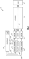
- Figure 1 is a schematic view of an example actuator control system 10.
- a plurality of motors 12A-C redundantly and cooperatively operate an actuator 14.
- the actuator moves a load 16.
- a controller 20 outputs control signals schematically shown as 22A-C to the plurality of motors 12A-C for controlling the plurality of motors 12 during a current update cycle.
- the actuator control system 10 includes at least one position sensor 24A, at least one velocity sensor 24B, and at least one electrical current sensor 24C.
- Figure 1 only depicts a single position sensor 24A, velocity sensor 24B, and electrical current sensor 24C, it is understood that in some examples each motor 12A-C has a dedicated position sensor 24A, dedicated velocity sensor 24B, and dedicated electrical current sensor 24C.
- the at least one position sensor 24A and at least one velocity sensor 24B for a given one of the motors 12 are the same sensor.
- the controller 20 obtains position feedback 26A from the at least one position sensor 24A, obtains velocity feedback 26B from the at least one velocity sensor 24B, and obtains electrical current feedback 26C from the at least one electrical current sensor 24C.
- the controller receives separate position feedback 26A, velocity feedback 26B, and electrical current feedback 26C for each of the motors 12A-C.
- the controller 20 updates the control signals 22A-C during a subsequent update cycle based on the feedback 26.
- the controller 20 includes memory 28 that stores a plurality of sets of predefined gain values that are used for determining the control signal 22. Each set of gain values corresponds to a quantity of the motors 12 that are active during a given update cycle.
- Each of the sensors 24A-C is associated with the actuator 14.
- the position sensor 24A measures a position of the actuator 14 or an associated one of the motors 12.
- the velocity sensor 24B measures a speed of movement of the actuator 14 or an associated one of the motors 12.
- the current sensor 24C measures an electrical current delivered to an associated one of the motors 12.
- the at least one position sensor 24A and velocity sensor 24B are the same sensor, and the velocity feedback 24B for a given one of the motors 12 is derived from the position feedback 26A for the given one of the motors.
- one or more of the sensors are linear variable differential transformers (LVDTs).
- the motors 12A-C are linear motors and the actuator 14 is a linear actuator that moves along a longitudinal axis L between various positions to linearly move the load 16.
- the load 16 includes a rotor of a rotorcraft, and the actuator 14 is configured to control an aspect of the rotor, such as an angle of attack of the rotor.
- loads 16 and other types of actuators 14 could be used in the system 10.
- other quantities of motors 12 could be used that cooperatively operate the actuator 14.
- the motors 12A-C provide for redundant operation of the actuator 14. If one of the motors 12 experiences a fault condition and/or becomes unavailable, the remaining active motors can compensate by increasing their output. If the controller 20 detects that one of the motors 12 is unavailable (e.g., based on the feedback 26 from sensors 24), it will adjust the control signal 22 accordingly to increase reliance on the available ones of the motors 12.
- FIG. 2 is a schematic view of an example implementation of the controller 20 of Figure 1 .
- the controller 20 includes three separate feedback loops 30A-C.
- Feedback loop 30A is a position loop that utilizes the position feedback 24A and a proportional (P) control 32.
- Feedback loop 30B is a velocity loop that utilizes the velocity feedback 24B and a proportional integral derivative (PID) control 34.
- Feedback loop 30C is an electrical current loop that utilizes the electrical current feedback 24C and a proportional integral (PI) control 36.
- the controller 20 implementation of Figure 2 is separately performed for each of the motors 12A-C based on the specific feedback for each of the motors for a given update cycle (e.g., update command 22A for motor 12A based on feedback from motor 12A, update command 22B for motor 12B based on feedback from motor 12B, and update command 22C for motor 12B based on feedback from motor 12C).
- Gain set 38A represents "simplex” gains for when a single one of the motors 12 is active.
- Gain set 38B represents “duplex” gains for when two of the motors 12 are active.
- Gain set 38C represents “triplex” gains for when all three of the motors 12 are active.
- a multiplexer 40 selects which of the gain sets 38 to use based on a quantity of the motors 12 that are currently active.
- the K p value represents a proportional gain for the feedback loop 30B
- the K i value represents an integral gain for the feedback loop 30B
- the K d value represents a derivative gain for the feedback loop 30B.
- a proportional gain K p_pos is used (with the "p” denoting proportional and the "pos” denoting position feedback loop 30A)
- a proportional gain K p_cur and integral gain K i_cur (with the "p” and "i” representing proportional and integral gains, respectively, and the "cur” denoting electrical current feedback loop 30C).
- the same K p_pos , K p_cur , and K i_cur values are used regardless of how many of the motors 12 are active.
- a command 42 is received indicating a desired position for a given one of the motors 12A-C 14.
- An actual position of the given motor 12 is received via feedback 24A and is subtracted by a summer 46 to obtain a position error 48, which the P control 32 multiplies by the proportional gain K p_pos to obtain a velocity demand 50.
- the velocity demand 50 is output by the proportional control 32 and provided to summer 52 in the velocity feedback loop 30B.
- the summer 52 subtracts an actual velocity value received as velocity feedback 24B from the velocity demand 50 to obtain a velocity error 54 that is provided to the PID control 34.
- the PID control 34 utilizes the velocity error 54 from the summer 52, along with the set 38 of gains corresponding to the number of motors 12 active during a current update cycle to determine an electrical current demand 56 which is required to close the position error 48.
- the electrical current demand 56 is provided to summer 58 in the electrical current feedback loop 30C.
- the summer 58 subtracts an electrical current feedback value 24C from the electrical current demand 56 to determine an electrical current error 59 which is provided to PI control 36.
- PI control 36 utilizes the electrical current error 59 along with the K p_c and K i_c gain values to determine a voltage demand needed to obtain a desired electrical current.
- the voltage demand is used as the control signal 22 that is provided to the given one of the motors 12, as shown in Figure 1 .
- the controller 20 provides an updated control signal 22 during each update cycle based on the feedback 26A-C received in the feedback loops 30A-C.
- the duration of an update cycle can be selected based on an intended application. In some examples, many update cycles occur per second.
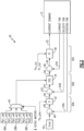
- FIG 3 is a schematic view of an example scaling feature for use in the PID control 34 of Figure 2 .
- the PID control 34 receives a gain set 38 as an input that includes gains K p_vel , K i_vel and K d_vel corresponding the quantity of motors 12 that are currently active.
- the PID block 34 also receives a velocity feedback value 24B from the feedback loop 30B and receives the velocity error 54 from summer 52.
- the PID control 34 includes a contribution determination block 60 that determines the electrical current demand 56 based on a proportional "P" contribution 62, integral "I” contribution 64, and derivative "D” contribution 66. Each of these P, I, and D contributions 62-66 are calculated during each update cycle.
- An output of the contribution determination block 60 (see "PID OUTPUT" in Figure 3 ) is provided as the electrical current demand 56 of Figure 2 .
- the electrical current demand 56 is the sum of the P contribution 62, I contribution 64, and D contribution 66.
- the contribution determination block 60 utilizes the I contribution from a preceding update cycle, also known as an "integral back value" 68 (and shown as “I_back_value” in Figure 3 ).
- the integral back value 68 is held in a delay buffer 74.
- the integral back value 68 from the preceding update cycle provides a historical component when determining the updated I contribution 64 for the current update cycle.
- the integral back value 68 is from an immediately preceding update cycle.
- the P contribution 62 and D contribution 66 are calculated based only on non-feedback inputs, whereas the I contribution 64 is determined based on feedback, including the integral back value 68.
- the PID control 34 takes a different approach by introducing a scaling feature 70 that selectively scales the integral back value 68 based on whether the gain set 38 has changed.
- a gain value comparison feature 72 compares the gain set 38 for a current update cycle against the gain set 38 from a preceding update cycle to determine if those values have changed based on a change in the quantity of active motors 12.
- the optional scaling 70 is not performed and the integral back value 68 is used from the preceding update cycle without scaling. However, if the gain values have changed, indicating a change in the quantity of active motors 12, the integral back value 68 is scaled using the optional scaling feature 70. This scaling mitigates the transient error that would otherwise occur in a position error signal.
- the scaling 70 is based on a ratio of the old gain value Ki old from the preceding update cycle to the new value Ki new of the current update cycle according to the following logic:
- I_back_value ⁇ Ki old Ki new represents a scaled integral back value 68 value that the integral back value 68 is expected to settle to.
- Figure 3 describes scaling 70 for an integral back value 68 of a PID control 34, the same scaling technique could be applied to non-PID controls that also use an integral term, such as the PI control 36.
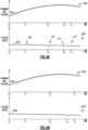
- Figure 4A illustrates a pair of graphs 80A, 82A that demonstrate transient values after changes in motor redundancy level.
- Graph 80A plots a position command and an actual position over time as 84A.
- the command and position 84A are represented by a single line because the command and position do not significantly differ from each other.
- the position and command 84A indicates that the actuator 14 is moving in a first direction until approximately time T4, at which the actuator 14 reverses direction.
- Graph 82A depicts a position error 86A corresponding to the feedback 24A from Figure 2 .
- all three motors 12 are active.
- the quantity of active motors 12 reduces to 1, and a transient value 88 value appears on line 86A. This transient value appears despite there being no difference between the command and actual position 84A at time T1.
- the quantity of active motors 12 increases from 1 to 2 and a second transient value 90 appears on line 86A.
- the quantity of active motors 12 increases from 2 to 3 and a third transient value 92 appears on the line 86A.
- the position time occurring at approximately T4 corresponds to the actuator 14 reversing direction, and provides a perturbance at 94 on the graph, but this is not an error due to a change in redundancy level.
- a graph 80B is shown with the same position and command 84B with the same changes in quantities of active motors at times T1, T2, and T3, and direction change at approximately T4.
- the PID control 34 in Figure 4B utilizes the scaling feature 70 discussed above and as shown the transient values 88, 90, and 92 no longer appear in graph 86B.
- Figure 5 schematically illustrates a flow chart 100 of an example method of controlling a plurality of actuator motors 12.
- An actuator 14 is cooperatively operated using a plurality of motors 12 (block 102).
- An output signal is determined for controlling active ones of the plurality of motors 12 during a current update cycle (block 104).
- the output signal is determined based on a first gain value (corresponding to a first quantity of the motors that are active during the current update cycle), an integral contribution from the current update cycle, and an integral contribution from a preceding update cycle.
- the integral contribution from the preceding update cycle is scaled for the output signal determination (block 106).
- the scaling is based on the first gain value and a second gain value from the preceding update cycle.
- Figure 2 utilizes a P control 32 for position feedback loop 30A, PID control for velocity feedback loop 30B, and PI control 36 for position feedback loop 30C, it is understood that this is a non-limiting example and that the various controls could be used for different ones of the loops (e.g., PID for position feedback loop 30A).
Landscapes
- Engineering & Computer Science (AREA)
- Physics & Mathematics (AREA)
- Automation & Control Theory (AREA)
- General Physics & Mathematics (AREA)
- Power Engineering (AREA)
- Computer Vision & Pattern Recognition (AREA)
- Software Systems (AREA)
- Medical Informatics (AREA)
- Evolutionary Computation (AREA)
- Health & Medical Sciences (AREA)
- Artificial Intelligence (AREA)
- Mechanical Engineering (AREA)
- Control Of Multiple Motors (AREA)
Claims (14)
- Aktuatorsteuerungssystem, umfassend:einen Linearaktuator (14);eine Vielzahl von Motoren (12), die dazu konfiguriert sind, den Linearaktuator zusammenwirkend zu betreiben; undeine Steuereinrichtung (20) mit einem Speicher, in dem eine Vielzahl von Sätzen vordefinierter Verstärkungswerte gespeichert ist, wobei die Steuereinrichtung (20) konfiguriert ist zum:
Bestimmen eines Ausgangssignals zum Steuern aktiver der Motoren während eines aktuellen Aktualisierungszyklus basierend auf einem ersten Verstärkungswert der vordefinierten Verstärkungswerte, einem Integralbeitrag aus dem aktuellen Aktualisierungszyklus und einem Integralbeitrag aus einem vorhergehenden Aktualisierungszyklus, wobei jeder Satz von Verstärkungswerten einer Menge der Vielzahl von Motoren entspricht, die während eines gegebenen Aktualisierungszyklus aktiv ist, und dadurch gekennzeichnet, dass die Steuereinrichtung ferner konfiguriert ist zum:
basierend darauf, dass eine Anzahl der Motoren, die aktiv ist, zwischen dem aktuellen und den vorhergehenden Aktualisierungszyklen unterschiedlich ist, Skalieren des Integralbeitrags aus dem vorhergehenden Aktualisierungszyklus für die Ausgabesignalbestimmung basierend auf dem ersten Verstärkungswert und einem zweiten Verstärkungswert der vordefinierten Verstärkungswerte aus dem vorhergehenden Aktualisierungszyklus. - Aktuatorsteuersystem nach Anspruch 1, wobei:
jeder Satz von vordefinierten Verstärkungswerten einen jeweiligen proportionalen Verstärkungswert, einen integralen Verstärkungswert und einen derivativen Verstärkungswert beinhaltet. - Aktuatorsteuerungssystem nach Anspruch 1 oder 2, wobei die Skalierung als Teil einer Proportional-Integral-Derivativ-, PID-, Funktion der Steuereinrichtung durchgeführt wird oder wobei die Skalierung als Teil einer Proportional-Integral-, PI-, Funktion der Steuereinrichtung durchgeführt wird.
- Aktuatorsteuerungssystem nach Anspruch 1 oder 2, wobei die Skalierung auf einem Verhältnis zwischen dem ersten und dem zweiten Verstärkungswert basiert, und wobei das Verhältnis vorzugsweise ein Verhältnis des zweiten Verstärkungswerts zum ersten Verstärkungswert ist, und die Skalierung eine Multiplikation des Integralbeitrags aus dem vorhergehenden Aktualisierungszyklus mit dem Verhältnis umfasst.
- Aktuatorsteuerungssystem nach Anspruch 4, wobei das Ausgangssignal ferner auf einem proportionalen Beitrag und einem derivativen Beitrag basiert, die beide aus dem aktuellen Aktualisierungszyklus stammen.
- Aktuatorsteuerungssystem nach einem der vorhergehenden Ansprüche, umfassend mindestens einen Sensor (24), der dazu konfiguriert ist, eine Rückkopplung von dem Aktuator oder von mindestens einem der Motoren bereitzustellen, wobei die Steuereinrichtung dazu konfiguriert ist, das Ausgangssignal basierend auf der Rückkopplung zu bestimmen.
- Aktuatorsteuerungssystem nach einem der vorhergehenden Ansprüche 1, wobei der Aktuator dazu konfiguriert ist, einen Rotor eines Drehflüglers zu steuern.
- Verfahren zum Steuern einer Vielzahl von Aktuatormotoren, umfassend:zusammenwirkendes Betreiben eines Linearaktuators unter Verwendung einer Vielzahl von Motoren;Bestimmen eines Ausgangssignals zum Steuern aktiver der Motoren während eines aktuellen Aktualisierungszyklus basierend auf einem ersten Verstärkungswert einer Vielzahl von Sätzen von gespeicherten vordefinierten Verstärkungswerten, einem Integralbeitrag aus dem aktuellen Aktualisierungszyklus und einem Integralbeitrag aus einem vorhergehenden Aktualisierungszyklus, wobei jeder Satz von Verstärkungswerten einer Menge der Vielzahl von Motoren entspricht, die während eines gegebenen Aktualisierungszyklus aktiv ist, und gekennzeichnet durchbasierend darauf, dass eine Anzahl der Motoren, die aktiv ist, zwischen dem aktuellen und den vorhergehenden Aktualisierungszyklen unterschiedlich ist, Skalieren des Integralbeitrags aus dem vorhergehenden Aktualisierungszyklus für die Ausgabesignalbestimmung basierend auf dem ersten Verstärkungswert und einem zweiten Verstärkungswert der Vielzahl von Sätzen von gespeicherten vordefinierten Verstärkungswerten aus dem vorhergehenden Aktualisierungszyklus.
- Verfahren nach Anspruch 8, umfassend:Auswählen des ersten Verstärkungswerts während des aktuellen Aktualisierungszyklus basierend auf einer Anzahl der Motoren, die während des aktuellen Aktualisierungszyklus aktiv ist;Auswählen des zweiten Verstärkungswerts während des vorhergehenden Aktualisierungszyklus basierend auf einer Anzahl der Motoren, die während des vorhergehenden Aktualisierungszyklus aktiv ist.
- Verfahren nach Anspruch 8 oder 9, wobei jeder Satz von gespeicherten vordefinierten Verstärkungswerten einen jeweiligen proportionalen Verstärkungswert, integralen Verstärkungswert und derivativen Verstärkungswert beinhaltet.
- Verfahren nach einem der Ansprüche 8 bis 10, wobei das Bestimmen und Skalieren als Teil einer Proportional-Integral-Differential-, PID-, Steuerungsfunktion durchgeführt werden oder wobei das Bestimmen und Skalieren als Teil einer Proportional-Integral-, PI-, Steuerungsfunktion durchgeführt werden.
- Verfahren nach einem der Ansprüche 8 bis 10, wobei das Skalieren auf einem Verhältnis zwischen dem ersten und dem zweiten Verstärkungswert basiert, und wobei das Verhältnis vorzugsweise ein Verhältnis des zweiten Verstärkungswerts zum ersten Verstärkungswert ist, und das Skalieren Multiplizieren des Integralbeitrags aus dem vorhergehenden Aktualisierungszyklus mit dem Verhältnis umfasst, und wobei das Bestimmen vorzugsweise ferner auf einem proportionalen Beitrag aus dem aktuellen Aktualisierungszyklus und einem derivativen Beitrag aus dem aktuellen Aktualisierungszyklus basiert.
- Verfahren nach einem der Ansprüche 8 bis 12, umfassend:Empfangen von Sensordaten von mindestens einem dem Aktuator zugeordneten Sensor;wobei das Bestimmen auf den Sensordaten basiert.
- Verfahren nach Anspruch 13, wobei das Empfangen von Sensordaten umfasst:Empfangen von Positionsdaten von einem Positionssensor (24A);Bestimmen von Geschwindigkeitsdaten aus den Positionsdaten; undEmpfangen von Daten zu elektrischem Strom von einem Sensor (24C) für elektrischen Strom.
Applications Claiming Priority (1)
| Application Number | Priority Date | Filing Date | Title |
|---|---|---|---|
| US15/898,877 US10338539B1 (en) | 2018-02-19 | 2018-02-19 | Actuator control system with transient reduction after redundancy level changes |
Publications (2)
| Publication Number | Publication Date |
|---|---|
| EP3528062A1 EP3528062A1 (de) | 2019-08-21 |
| EP3528062B1 true EP3528062B1 (de) | 2024-08-14 |
Family
ID=65628535
Family Applications (1)
| Application Number | Title | Priority Date | Filing Date |
|---|---|---|---|
| EP19157951.5A Active EP3528062B1 (de) | 2018-02-19 | 2019-02-19 | Aktuatorsteuerungssystem mit transienter reduktion nach redundanzpegelwechseln |
Country Status (2)
| Country | Link |
|---|---|
| US (1) | US10338539B1 (de) |
| EP (1) | EP3528062B1 (de) |
Families Citing this family (1)
| Publication number | Priority date | Publication date | Assignee | Title |
|---|---|---|---|---|
| CN109799699B (zh) * | 2019-02-19 | 2022-06-07 | 阿波罗智能技术(北京)有限公司 | 自动驾驶系统控制参数处理方法、装置、设备、存储介质 |
Family Cites Families (8)
| Publication number | Priority date | Publication date | Assignee | Title |
|---|---|---|---|---|
| US5206570A (en) | 1991-03-19 | 1993-04-27 | Maxtor Corporation | Actuator servo compensation method |
| US5949675A (en) * | 1996-11-01 | 1999-09-07 | Space Systems/Loral, Inc. | Transient-free gain switching within error threshold |
| JP6007986B2 (ja) * | 2012-09-25 | 2016-10-19 | 株式会社安川電機 | モータ制御装置 |
| US9327761B2 (en) * | 2014-01-29 | 2016-05-03 | Nsk Ltd. | Electric power steering apparatus |
| WO2017026234A1 (ja) | 2015-08-07 | 2017-02-16 | 学校法人慶應義塾 | 振動制御装置、振動制御方法、振動制御システム、プログラム及び記録媒体 |
| US10291166B2 (en) * | 2017-03-13 | 2019-05-14 | Rockwell Automation Technologies, Inc. | System and method of single parameter ratiometric tuning for motor drives |
| JP6913488B2 (ja) * | 2017-03-21 | 2021-08-04 | 株式会社Screenホールディングス | 搬送制御方法及び搬送装置並びに印刷装置 |
| JP6882667B2 (ja) * | 2017-03-29 | 2021-06-02 | シンフォニアテクノロジー株式会社 | 駆動ギヤのロック制御装置及びアクチュエータのロック制御装置 |
-
2018
- 2018-02-19 US US15/898,877 patent/US10338539B1/en active Active
-
2019
- 2019-02-19 EP EP19157951.5A patent/EP3528062B1/de active Active
Also Published As
| Publication number | Publication date |
|---|---|
| US10338539B1 (en) | 2019-07-02 |
| EP3528062A1 (de) | 2019-08-21 |
Similar Documents
| Publication | Publication Date | Title |
|---|---|---|
| US20080218116A1 (en) | Servo controller | |
| KR20010108037A (ko) | 수치제어장치 | |
| EP1826416A2 (de) | Hydraulikschaltung einer Baumaschine | |
| EP1798615A2 (de) | Festpositions-Anhaltesteuervorrichtung für eine Drehwelle | |
| US20240102388A1 (en) | Valve Position Control | |
| EP3220214B1 (de) | Steuerparameterabstimmungsvorrichtung und steuerparameterabstimmungsverfahren | |
| US20070250183A1 (en) | Method for synchronization of a controller | |
| CN105629719A (zh) | 马达控制装置及马达控制方法 | |
| EP3528062A1 (de) | Aktuatorsteuerungssystem mit transienter reduktion nach redundanzpegelwechseln | |
| US4742444A (en) | Method of optimizing drive controls in machine tools having computer control | |
| CN117678155A (zh) | 频率特性预测装置及频率特性预测方法 | |
| CN110941242A (zh) | 电动机控制装置 | |
| EP1025467A1 (de) | Verfahren zur einstellung der reglerparameter eines zustandsreglers | |
| JP4282631B2 (ja) | テーブル形式データで運転を行う数値制御装置 | |
| CN106292575A (zh) | 用于基于阀的特性曲线和比例积分微分信号值的组合来控制阀的方法、装置和系统 | |
| US11086277B2 (en) | System and method for determining the parameters of a controller | |
| US6738688B2 (en) | Method of predicting carrying time in automatic warehouse system | |
| WO2002025390A1 (en) | Servo control method | |
| JP2006302208A (ja) | 数値制御装置 | |
| CN118622676A (zh) | 泵校正系统和泵校正方法 | |
| JP2018516407A (ja) | 負荷に応じたゲインとpコントローラとを用いた切削加工工程の制御 | |
| US20190027170A1 (en) | Servo control method having first and second trajectory generation units | |
| JP2018112858A (ja) | 制御装置、制御方法、制御プログラム | |
| JP5824370B2 (ja) | フルクローズド位置制御装置 | |
| JPH04220701A (ja) | 流体制御システム |
Legal Events
| Date | Code | Title | Description |
|---|---|---|---|
| PUAI | Public reference made under article 153(3) epc to a published international application that has entered the european phase |
Free format text: ORIGINAL CODE: 0009012 |
|
| STAA | Information on the status of an ep patent application or granted ep patent |
Free format text: STATUS: THE APPLICATION HAS BEEN PUBLISHED |
|
| AK | Designated contracting states |
Kind code of ref document: A1 Designated state(s): AL AT BE BG CH CY CZ DE DK EE ES FI FR GB GR HR HU IE IS IT LI LT LU LV MC MK MT NL NO PL PT RO RS SE SI SK SM TR |
|
| AX | Request for extension of the european patent |
Extension state: BA ME |
|
| RIN1 | Information on inventor provided before grant (corrected) |
Inventor name: AVRITCH, STEVEN A. Inventor name: DICKIE, DAVID F. Inventor name: ELDRIDGE, JEFFREY A. |
|
| STAA | Information on the status of an ep patent application or granted ep patent |
Free format text: STATUS: REQUEST FOR EXAMINATION WAS MADE |
|
| 17P | Request for examination filed |
Effective date: 20191121 |
|
| RBV | Designated contracting states (corrected) |
Designated state(s): AL AT BE BG CH CY CZ DE DK EE ES FI FR GB GR HR HU IE IS IT LI LT LU LV MC MK MT NL NO PL PT RO RS SE SI SK SM TR |
|
| STAA | Information on the status of an ep patent application or granted ep patent |
Free format text: STATUS: EXAMINATION IS IN PROGRESS |
|
| 17Q | First examination report despatched |
Effective date: 20210906 |
|
| GRAP | Despatch of communication of intention to grant a patent |
Free format text: ORIGINAL CODE: EPIDOSNIGR1 |
|
| STAA | Information on the status of an ep patent application or granted ep patent |
Free format text: STATUS: GRANT OF PATENT IS INTENDED |
|
| RIC1 | Information provided on ipc code assigned before grant |
Ipc: H02P 9/00 20060101ALI20240229BHEP Ipc: H02P 25/06 20160101ALI20240229BHEP Ipc: H02P 5/747 20060101ALI20240229BHEP Ipc: G05B 13/04 20060101ALI20240229BHEP Ipc: G05B 11/42 20060101AFI20240229BHEP |
|
| INTG | Intention to grant announced |
Effective date: 20240315 |
|
| GRAS | Grant fee paid |
Free format text: ORIGINAL CODE: EPIDOSNIGR3 |
|
| GRAA | (expected) grant |
Free format text: ORIGINAL CODE: 0009210 |
|
| STAA | Information on the status of an ep patent application or granted ep patent |
Free format text: STATUS: THE PATENT HAS BEEN GRANTED |
|
| AK | Designated contracting states |
Kind code of ref document: B1 Designated state(s): AL AT BE BG CH CY CZ DE DK EE ES FI FR GB GR HR HU IE IS IT LI LT LU LV MC MK MT NL NO PL PT RO RS SE SI SK SM TR |
|
| REG | Reference to a national code |
Ref country code: GB Ref legal event code: FG4D |
|
| REG | Reference to a national code |
Ref country code: CH Ref legal event code: EP |
|
| REG | Reference to a national code |
Ref country code: DE Ref legal event code: R096 Ref document number: 602019056874 Country of ref document: DE |
|
| REG | Reference to a national code |
Ref country code: IE Ref legal event code: FG4D |
|
| REG | Reference to a national code |
Ref country code: LT Ref legal event code: MG9D |
|
| REG | Reference to a national code |
Ref country code: NL Ref legal event code: MP Effective date: 20240814 |
|
| PG25 | Lapsed in a contracting state [announced via postgrant information from national office to epo] |
Ref country code: NO Free format text: LAPSE BECAUSE OF FAILURE TO SUBMIT A TRANSLATION OF THE DESCRIPTION OR TO PAY THE FEE WITHIN THE PRESCRIBED TIME-LIMIT Effective date: 20241114 |
|
| REG | Reference to a national code |
Ref country code: AT Ref legal event code: MK05 Ref document number: 1713871 Country of ref document: AT Kind code of ref document: T Effective date: 20240814 |
|
| PG25 | Lapsed in a contracting state [announced via postgrant information from national office to epo] |
Ref country code: GR Free format text: LAPSE BECAUSE OF FAILURE TO SUBMIT A TRANSLATION OF THE DESCRIPTION OR TO PAY THE FEE WITHIN THE PRESCRIBED TIME-LIMIT Effective date: 20241115 Ref country code: NL Free format text: LAPSE BECAUSE OF FAILURE TO SUBMIT A TRANSLATION OF THE DESCRIPTION OR TO PAY THE FEE WITHIN THE PRESCRIBED TIME-LIMIT Effective date: 20240814 Ref country code: PT Free format text: LAPSE BECAUSE OF FAILURE TO SUBMIT A TRANSLATION OF THE DESCRIPTION OR TO PAY THE FEE WITHIN THE PRESCRIBED TIME-LIMIT Effective date: 20241216 Ref country code: PL Free format text: LAPSE BECAUSE OF FAILURE TO SUBMIT A TRANSLATION OF THE DESCRIPTION OR TO PAY THE FEE WITHIN THE PRESCRIBED TIME-LIMIT Effective date: 20240814 Ref country code: FI Free format text: LAPSE BECAUSE OF FAILURE TO SUBMIT A TRANSLATION OF THE DESCRIPTION OR TO PAY THE FEE WITHIN THE PRESCRIBED TIME-LIMIT Effective date: 20240814 |
|
| PG25 | Lapsed in a contracting state [announced via postgrant information from national office to epo] |
Ref country code: BG Free format text: LAPSE BECAUSE OF FAILURE TO SUBMIT A TRANSLATION OF THE DESCRIPTION OR TO PAY THE FEE WITHIN THE PRESCRIBED TIME-LIMIT Effective date: 20240814 |
|
| PG25 | Lapsed in a contracting state [announced via postgrant information from national office to epo] |
Ref country code: LV Free format text: LAPSE BECAUSE OF FAILURE TO SUBMIT A TRANSLATION OF THE DESCRIPTION OR TO PAY THE FEE WITHIN THE PRESCRIBED TIME-LIMIT Effective date: 20240814 |
|
| PG25 | Lapsed in a contracting state [announced via postgrant information from national office to epo] |
Ref country code: AT Free format text: LAPSE BECAUSE OF FAILURE TO SUBMIT A TRANSLATION OF THE DESCRIPTION OR TO PAY THE FEE WITHIN THE PRESCRIBED TIME-LIMIT Effective date: 20240814 Ref country code: IS Free format text: LAPSE BECAUSE OF FAILURE TO SUBMIT A TRANSLATION OF THE DESCRIPTION OR TO PAY THE FEE WITHIN THE PRESCRIBED TIME-LIMIT Effective date: 20241214 |
|
| PG25 | Lapsed in a contracting state [announced via postgrant information from national office to epo] |
Ref country code: HR Free format text: LAPSE BECAUSE OF FAILURE TO SUBMIT A TRANSLATION OF THE DESCRIPTION OR TO PAY THE FEE WITHIN THE PRESCRIBED TIME-LIMIT Effective date: 20240814 |
|
| PG25 | Lapsed in a contracting state [announced via postgrant information from national office to epo] |
Ref country code: RS Free format text: LAPSE BECAUSE OF FAILURE TO SUBMIT A TRANSLATION OF THE DESCRIPTION OR TO PAY THE FEE WITHIN THE PRESCRIBED TIME-LIMIT Effective date: 20241114 Ref country code: ES Free format text: LAPSE BECAUSE OF FAILURE TO SUBMIT A TRANSLATION OF THE DESCRIPTION OR TO PAY THE FEE WITHIN THE PRESCRIBED TIME-LIMIT Effective date: 20240814 |
|
| PG25 | Lapsed in a contracting state [announced via postgrant information from national office to epo] |
Ref country code: RS Free format text: LAPSE BECAUSE OF FAILURE TO SUBMIT A TRANSLATION OF THE DESCRIPTION OR TO PAY THE FEE WITHIN THE PRESCRIBED TIME-LIMIT Effective date: 20241114 Ref country code: PT Free format text: LAPSE BECAUSE OF FAILURE TO SUBMIT A TRANSLATION OF THE DESCRIPTION OR TO PAY THE FEE WITHIN THE PRESCRIBED TIME-LIMIT Effective date: 20241216 Ref country code: PL Free format text: LAPSE BECAUSE OF FAILURE TO SUBMIT A TRANSLATION OF THE DESCRIPTION OR TO PAY THE FEE WITHIN THE PRESCRIBED TIME-LIMIT Effective date: 20240814 Ref country code: NO Free format text: LAPSE BECAUSE OF FAILURE TO SUBMIT A TRANSLATION OF THE DESCRIPTION OR TO PAY THE FEE WITHIN THE PRESCRIBED TIME-LIMIT Effective date: 20241114 Ref country code: NL Free format text: LAPSE BECAUSE OF FAILURE TO SUBMIT A TRANSLATION OF THE DESCRIPTION OR TO PAY THE FEE WITHIN THE PRESCRIBED TIME-LIMIT Effective date: 20240814 Ref country code: LV Free format text: LAPSE BECAUSE OF FAILURE TO SUBMIT A TRANSLATION OF THE DESCRIPTION OR TO PAY THE FEE WITHIN THE PRESCRIBED TIME-LIMIT Effective date: 20240814 Ref country code: IS Free format text: LAPSE BECAUSE OF FAILURE TO SUBMIT A TRANSLATION OF THE DESCRIPTION OR TO PAY THE FEE WITHIN THE PRESCRIBED TIME-LIMIT Effective date: 20241214 Ref country code: HR Free format text: LAPSE BECAUSE OF FAILURE TO SUBMIT A TRANSLATION OF THE DESCRIPTION OR TO PAY THE FEE WITHIN THE PRESCRIBED TIME-LIMIT Effective date: 20240814 Ref country code: GR Free format text: LAPSE BECAUSE OF FAILURE TO SUBMIT A TRANSLATION OF THE DESCRIPTION OR TO PAY THE FEE WITHIN THE PRESCRIBED TIME-LIMIT Effective date: 20241115 Ref country code: FI Free format text: LAPSE BECAUSE OF FAILURE TO SUBMIT A TRANSLATION OF THE DESCRIPTION OR TO PAY THE FEE WITHIN THE PRESCRIBED TIME-LIMIT Effective date: 20240814 Ref country code: ES Free format text: LAPSE BECAUSE OF FAILURE TO SUBMIT A TRANSLATION OF THE DESCRIPTION OR TO PAY THE FEE WITHIN THE PRESCRIBED TIME-LIMIT Effective date: 20240814 Ref country code: BG Free format text: LAPSE BECAUSE OF FAILURE TO SUBMIT A TRANSLATION OF THE DESCRIPTION OR TO PAY THE FEE WITHIN THE PRESCRIBED TIME-LIMIT Effective date: 20240814 Ref country code: AT Free format text: LAPSE BECAUSE OF FAILURE TO SUBMIT A TRANSLATION OF THE DESCRIPTION OR TO PAY THE FEE WITHIN THE PRESCRIBED TIME-LIMIT Effective date: 20240814 |
|
| PG25 | Lapsed in a contracting state [announced via postgrant information from national office to epo] |
Ref country code: RO Free format text: LAPSE BECAUSE OF FAILURE TO SUBMIT A TRANSLATION OF THE DESCRIPTION OR TO PAY THE FEE WITHIN THE PRESCRIBED TIME-LIMIT Effective date: 20240814 Ref country code: DK Free format text: LAPSE BECAUSE OF FAILURE TO SUBMIT A TRANSLATION OF THE DESCRIPTION OR TO PAY THE FEE WITHIN THE PRESCRIBED TIME-LIMIT Effective date: 20240814 Ref country code: SM Free format text: LAPSE BECAUSE OF FAILURE TO SUBMIT A TRANSLATION OF THE DESCRIPTION OR TO PAY THE FEE WITHIN THE PRESCRIBED TIME-LIMIT Effective date: 20240814 |
|
| PG25 | Lapsed in a contracting state [announced via postgrant information from national office to epo] |
Ref country code: EE Free format text: LAPSE BECAUSE OF FAILURE TO SUBMIT A TRANSLATION OF THE DESCRIPTION OR TO PAY THE FEE WITHIN THE PRESCRIBED TIME-LIMIT Effective date: 20240814 |
|
| PG25 | Lapsed in a contracting state [announced via postgrant information from national office to epo] |
Ref country code: CZ Free format text: LAPSE BECAUSE OF FAILURE TO SUBMIT A TRANSLATION OF THE DESCRIPTION OR TO PAY THE FEE WITHIN THE PRESCRIBED TIME-LIMIT Effective date: 20240814 |
|
| PG25 | Lapsed in a contracting state [announced via postgrant information from national office to epo] |
Ref country code: IT Free format text: LAPSE BECAUSE OF FAILURE TO SUBMIT A TRANSLATION OF THE DESCRIPTION OR TO PAY THE FEE WITHIN THE PRESCRIBED TIME-LIMIT Effective date: 20240814 Ref country code: SK Free format text: LAPSE BECAUSE OF FAILURE TO SUBMIT A TRANSLATION OF THE DESCRIPTION OR TO PAY THE FEE WITHIN THE PRESCRIBED TIME-LIMIT Effective date: 20240814 |
|
| REG | Reference to a national code |
Ref country code: DE Ref legal event code: R097 Ref document number: 602019056874 Country of ref document: DE |
|
| PLBE | No opposition filed within time limit |
Free format text: ORIGINAL CODE: 0009261 |
|
| STAA | Information on the status of an ep patent application or granted ep patent |
Free format text: STATUS: NO OPPOSITION FILED WITHIN TIME LIMIT |
|
| 26N | No opposition filed |
Effective date: 20250515 |
|
| PG25 | Lapsed in a contracting state [announced via postgrant information from national office to epo] |
Ref country code: SE Free format text: LAPSE BECAUSE OF FAILURE TO SUBMIT A TRANSLATION OF THE DESCRIPTION OR TO PAY THE FEE WITHIN THE PRESCRIBED TIME-LIMIT Effective date: 20240814 |
|
| PG25 | Lapsed in a contracting state [announced via postgrant information from national office to epo] |
Ref country code: MC Free format text: LAPSE BECAUSE OF FAILURE TO SUBMIT A TRANSLATION OF THE DESCRIPTION OR TO PAY THE FEE WITHIN THE PRESCRIBED TIME-LIMIT Effective date: 20240814 |
|
| REG | Reference to a national code |
Ref country code: CH Ref legal event code: PL |
|
| PG25 | Lapsed in a contracting state [announced via postgrant information from national office to epo] |
Ref country code: LU Free format text: LAPSE BECAUSE OF NON-PAYMENT OF DUE FEES Effective date: 20250219 |
|
| PG25 | Lapsed in a contracting state [announced via postgrant information from national office to epo] |
Ref country code: CH Free format text: LAPSE BECAUSE OF NON-PAYMENT OF DUE FEES Effective date: 20250228 |
|
| REG | Reference to a national code |
Ref country code: BE Ref legal event code: MM Effective date: 20250228 |
|
| PG25 | Lapsed in a contracting state [announced via postgrant information from national office to epo] |
Ref country code: BE Free format text: LAPSE BECAUSE OF NON-PAYMENT OF DUE FEES Effective date: 20250228 |
|
| PG25 | Lapsed in a contracting state [announced via postgrant information from national office to epo] |
Ref country code: IE Free format text: LAPSE BECAUSE OF NON-PAYMENT OF DUE FEES Effective date: 20250219 |
|
| PGFP | Annual fee paid to national office [announced via postgrant information from national office to epo] |
Ref country code: GB Payment date: 20260122 Year of fee payment: 8 |
|
| PGFP | Annual fee paid to national office [announced via postgrant information from national office to epo] |
Ref country code: DE Payment date: 20260121 Year of fee payment: 8 |
|
| PGFP | Annual fee paid to national office [announced via postgrant information from national office to epo] |
Ref country code: FR Payment date: 20260121 Year of fee payment: 8 |