EP3528009B1 - System und verfahren zum deketieren eines tunnels für ein fahrzeug - Google Patents
System und verfahren zum deketieren eines tunnels für ein fahrzeug Download PDFInfo
- Publication number
- EP3528009B1 EP3528009B1 EP19154233.1A EP19154233A EP3528009B1 EP 3528009 B1 EP3528009 B1 EP 3528009B1 EP 19154233 A EP19154233 A EP 19154233A EP 3528009 B1 EP3528009 B1 EP 3528009B1
- Authority
- EP
- European Patent Office
- Prior art keywords
- tunnel
- variation
- amplitude
- vehicle
- detection system
- Prior art date
- Legal status (The legal status is an assumption and is not a legal conclusion. Google has not performed a legal analysis and makes no representation as to the accuracy of the status listed.)
- Active
Links
Images


Classifications
-
- G—PHYSICS
- G01—MEASURING; TESTING
- G01S—RADIO DIRECTION-FINDING; RADIO NAVIGATION; DETERMINING DISTANCE OR VELOCITY BY USE OF RADIO WAVES; LOCATING OR PRESENCE-DETECTING BY USE OF THE REFLECTION OR RERADIATION OF RADIO WAVES; ANALOGOUS ARRANGEMENTS USING OTHER WAVES
- G01S19/00—Satellite radio beacon positioning systems; Determining position, velocity or attitude using signals transmitted by such systems
- G01S19/01—Satellite radio beacon positioning systems transmitting time-stamped messages, e.g. GPS [Global Positioning System], GLONASS [Global Orbiting Navigation Satellite System] or GALILEO
- G01S19/13—Receivers
- G01S19/14—Receivers specially adapted for specific applications
-
- B—PERFORMING OPERATIONS; TRANSPORTING
- B60—VEHICLES IN GENERAL
- B60W—CONJOINT CONTROL OF VEHICLE SUB-UNITS OF DIFFERENT TYPE OR DIFFERENT FUNCTION; CONTROL SYSTEMS SPECIALLY ADAPTED FOR HYBRID VEHICLES; ROAD VEHICLE DRIVE CONTROL SYSTEMS FOR PURPOSES NOT RELATED TO THE CONTROL OF A PARTICULAR SUB-UNIT
- B60W40/00—Estimation or calculation of non-directly measurable driving parameters for road vehicle drive control systems not related to the control of a particular sub unit, e.g. by using mathematical models
-
- G—PHYSICS
- G01—MEASURING; TESTING
- G01S—RADIO DIRECTION-FINDING; RADIO NAVIGATION; DETERMINING DISTANCE OR VELOCITY BY USE OF RADIO WAVES; LOCATING OR PRESENCE-DETECTING BY USE OF THE REFLECTION OR RERADIATION OF RADIO WAVES; ANALOGOUS ARRANGEMENTS USING OTHER WAVES
- G01S19/00—Satellite radio beacon positioning systems; Determining position, velocity or attitude using signals transmitted by such systems
- G01S19/38—Determining a navigation solution using signals transmitted by a satellite radio beacon positioning system
- G01S19/39—Determining a navigation solution using signals transmitted by a satellite radio beacon positioning system the satellite radio beacon positioning system transmitting time-stamped messages, e.g. GPS [Global Positioning System], GLONASS [Global Orbiting Navigation Satellite System] or GALILEO
-
- G—PHYSICS
- G01—MEASURING; TESTING
- G01S—RADIO DIRECTION-FINDING; RADIO NAVIGATION; DETERMINING DISTANCE OR VELOCITY BY USE OF RADIO WAVES; LOCATING OR PRESENCE-DETECTING BY USE OF THE REFLECTION OR RERADIATION OF RADIO WAVES; ANALOGOUS ARRANGEMENTS USING OTHER WAVES
- G01S19/00—Satellite radio beacon positioning systems; Determining position, velocity or attitude using signals transmitted by such systems
- G01S19/38—Determining a navigation solution using signals transmitted by a satellite radio beacon positioning system
- G01S19/39—Determining a navigation solution using signals transmitted by a satellite radio beacon positioning system the satellite radio beacon positioning system transmitting time-stamped messages, e.g. GPS [Global Positioning System], GLONASS [Global Orbiting Navigation Satellite System] or GALILEO
- G01S19/42—Determining position
-
- G—PHYSICS
- G01—MEASURING; TESTING
- G01S—RADIO DIRECTION-FINDING; RADIO NAVIGATION; DETERMINING DISTANCE OR VELOCITY BY USE OF RADIO WAVES; LOCATING OR PRESENCE-DETECTING BY USE OF THE REFLECTION OR RERADIATION OF RADIO WAVES; ANALOGOUS ARRANGEMENTS USING OTHER WAVES
- G01S5/00—Position-fixing by co-ordinating two or more direction or position line determinations; Position-fixing by co-ordinating two or more distance determinations
- G01S5/01—Determining conditions which influence positioning, e.g. radio environment, state of motion or energy consumption
- G01S5/014—Identifying transitions between environments
-
- G—PHYSICS
- G01—MEASURING; TESTING
- G01S—RADIO DIRECTION-FINDING; RADIO NAVIGATION; DETERMINING DISTANCE OR VELOCITY BY USE OF RADIO WAVES; LOCATING OR PRESENCE-DETECTING BY USE OF THE REFLECTION OR RERADIATION OF RADIO WAVES; ANALOGOUS ARRANGEMENTS USING OTHER WAVES
- G01S5/00—Position-fixing by co-ordinating two or more direction or position line determinations; Position-fixing by co-ordinating two or more distance determinations
- G01S5/01—Determining conditions which influence positioning, e.g. radio environment, state of motion or energy consumption
- G01S5/014—Identifying transitions between environments
- G01S5/015—Identifying transitions between environments between indoor and outdoor environments
-
- G—PHYSICS
- G08—SIGNALLING
- G08G—TRAFFIC CONTROL SYSTEMS
- G08G1/00—Traffic control systems for road vehicles
- G08G1/01—Detecting movement of traffic to be counted or controlled
- G08G1/0104—Measuring and analyzing of parameters relative to traffic conditions
- G08G1/0108—Measuring and analyzing of parameters relative to traffic conditions based on the source of data
- G08G1/012—Measuring and analyzing of parameters relative to traffic conditions based on the source of data from other sources than vehicle or roadside beacons, e.g. mobile networks
-
- G—PHYSICS
- G08—SIGNALLING
- G08G—TRAFFIC CONTROL SYSTEMS
- G08G1/00—Traffic control systems for road vehicles
- G08G1/01—Detecting movement of traffic to be counted or controlled
- G08G1/0104—Measuring and analyzing of parameters relative to traffic conditions
- G08G1/0137—Measuring and analyzing of parameters relative to traffic conditions for specific applications
-
- B—PERFORMING OPERATIONS; TRANSPORTING
- B60—VEHICLES IN GENERAL
- B60Q—ARRANGEMENT OF SIGNALLING OR LIGHTING DEVICES, THE MOUNTING OR SUPPORTING THEREOF OR CIRCUITS THEREFOR, FOR VEHICLES IN GENERAL
- B60Q2300/00—Indexing codes for automatically adjustable headlamps or automatically dimmable headlamps
- B60Q2300/30—Indexing codes relating to the vehicle environment
- B60Q2300/33—Driving situation
- B60Q2300/337—Tunnels or bridges
-
- B—PERFORMING OPERATIONS; TRANSPORTING
- B60—VEHICLES IN GENERAL
- B60W—CONJOINT CONTROL OF VEHICLE SUB-UNITS OF DIFFERENT TYPE OR DIFFERENT FUNCTION; CONTROL SYSTEMS SPECIALLY ADAPTED FOR HYBRID VEHICLES; ROAD VEHICLE DRIVE CONTROL SYSTEMS FOR PURPOSES NOT RELATED TO THE CONTROL OF A PARTICULAR SUB-UNIT
- B60W2552/00—Input parameters relating to infrastructure
-
- B—PERFORMING OPERATIONS; TRANSPORTING
- B60—VEHICLES IN GENERAL
- B60W—CONJOINT CONTROL OF VEHICLE SUB-UNITS OF DIFFERENT TYPE OR DIFFERENT FUNCTION; CONTROL SYSTEMS SPECIALLY ADAPTED FOR HYBRID VEHICLES; ROAD VEHICLE DRIVE CONTROL SYSTEMS FOR PURPOSES NOT RELATED TO THE CONTROL OF A PARTICULAR SUB-UNIT
- B60W2555/00—Input parameters relating to exterior conditions, not covered by groups B60W2552/00, B60W2554/00
- B60W2555/20—Ambient conditions, e.g. wind or rain
Definitions
- the present invention relates to a tunnel detection system for a motor vehicle as well as to the method of detection of the tunnel by the system.
- Tunnel detection by a detection system comprising cameras in a vehicle is known. This detection is generally based on the recognition of road signs. Tunnel detection makes it possible to adapt the driver assistance devices when the vehicle is passing through the tunnel.
- tunnel detection by radar signal is tunnel detection by radar signal.
- this alternative is not very robust and can be traced back to devices to aid in the conduct of false information.
- the most feared example concerns false obstacle detection in the path of the vehicle instead of tunnel detection.
- this function can be activated incorrectly since the vehicle is simply in a tunnel whose structure causes reflections of radar waves falsely interpreted as the presence of an obstacle in the path of the vehicle.
- US 2015/296041 A1 discloses a method in which constraint data, associated with a mobile communication device performing a communication session associated with a mobile application using a wireless connection, is collected. Weight values are assigned to the stress data. A score for the communication session is generated based on the data, with each data being modified based on the weight corresponding. If the score is in a first range, a context corresponding to the communication session is stored and the session is extended. If the score is in a second range different from the first, the context is stored and the communication session is maintained as a transient session. If the score is neither in the first range nor in the second range, the communication session is terminated.
- US 2006/271295 A1 describes a navigation system for improving the reliability of estimation of a solution of the navigation system.
- DE 10 2015 016045 A1 describes a system for determining the position of a vehicle for verifying whether the vehicle is located in an area covered by a ceiling element of a structure.
- the aim of the invention is to be able to detect the crossing of a vehicle in a tunnel using only standard sensors on board the vehicle without the need for additional sensors such as a camera or a radar.
- the substitution of the device for detecting a tunnel by camera by the invention makes it possible to detect whether the vehicle is entering or exiting a tunnel in order to be able to make the necessary adaptations in the vehicle.
- a tunnel detection system for a motor vehicle is defined by claim 1.
- the radio frequency signal receiver can include a satellite geolocation system.
- the variation of the predetermined reference signal amplitude may comprise a variation of predetermined exponential decreasing or predetermined exponential increasing amplitude representative respectively of the passage of the receiver in a tunnel entrance or in a tunnel exit so as to be able to detect the tunnel crossed by the detection system.
- a motor vehicle comprises the tunnel detection system of the first embodiment.
- the motor vehicle may include an automatic emergency braking device by radar detection. electrically connected to the tunnel detection system so that the tunnel detection system can authorize or not automatic emergency braking.
- a method of detecting a tunnel by a motor vehicle comprising the detection system of the first embodiment comprises the steps defined in claim 5.
- the step of determining at least one level of correspondence can comprise a step of determining at least one level of correspondence representative of the difference between the detected amplitude variation of the radio frequency signal with a predetermined exponential decreasing or predetermined exponential increasing amplitude variation. representative respectively of the passage of the receiver in a tunnel entrance or in a tunnel exit.
- a method of activating an automatic emergency braking function of a vehicle comprising the detection method described above comprises a step of authorizing the automatic emergency braking function during the detection of the tunnel crossed by the detection system.
- a motor vehicle 10 is shown going through a tunnel 12.
- the crossing of the tunnel 12 takes place in three phases.
- the vehicle 10 is shown in the three phases of crossing the tunnel.
- the vehicle is shown a first time in the first phase, the said first phase consisting of the passage of the vehicle 10 into the entrance 14 of the tunnel 12.
- the vehicle 10 is shown a second time (in dotted lines), by transparency through the tunnel 12, in the second phase, said second phase consisting of the taxiing of the vehicle 10 inside tunnel 12.
- Vehicle 10 is shown a third time in the third phase, said third phase consisting of vehicle 10 passing through exit 16 of tunnel 12.
- the vehicle 10 is subjected to various radiofrequency waves 18, 20 coming from sources external to the vehicle 10.
- the radiofrequency waves 18, 20 can come from a satellite 22 of geolocation provided for the operation of the monitoring devices.
- geolocation by satellite (GPS) of radio stations provided for the operation of car radios or even of telephony relay antennas 24 provided for the operation of mobile telephony devices.
- Vehicle 10 is also subjected to various weather conditions.
- the meteorological conditions can be sunshine 26 causing significant luminosity in the environment of the vehicle 10, rain showers 28, a phenomenon of wind, snow showers, high or low temperatures. ..
- the vehicle comprises at least one receiver 30 of radiofrequency signals originating from sources external to the vehicle 10.
- the receiver 30 of radiofrequency signals can be a satellite geolocation device (GPS), a car radio or even a device. telephone signal reception.
- GPS satellite geolocation device
- car radio or even a device. telephone signal reception.
- the vehicle 10 also includes at least one weather condition sensor 32, that is to say at least one sensor 32 capable of detecting a phenomenon due to the weather such as sunshine 26, rain showers 28, wind, snow, temperature, etc.
- the vehicle may include a brightness sensor 32 generally cooperating with the exterior and interior lighting of the vehicle, or else a sensor 32 rain cooperating with the windscreen wipers.
- the radiofrequency wave sensors 32 and receivers 30 mentioned above are generally standard sensors / receivers integrated into the vehicle (such as a GPS receiver, a light sensor, etc.) providing samples of the force / force. the signal strength measured by the sensor in time / space.
- a graph 34 illustrating an example of variation in amplitude detected of a radio frequency signal received by the receiver 30 of the radio frequency signal of the vehicle 10 is shown. More particularly, the circles 43 represent samples for measuring the amplitude of the GPS signal received by the GPS device of the vehicle 10 during the crossing of the vehicle 10 in a tunnel 12. In other words, it is the variation of amplitude of the GPS signal received by the GPS device of the vehicle 10 when the vehicle transits from an 'open air' environment 48 to an 'under tunnel' environment 50 then from the 'under tunnel' environment 50 to the 'open air' environment 48.
- the x-axis represents a distance d extending from the entrance 14 of the tunnel 12 to the exit 16 of the tunnel 12.
- the y-axis represents the variation in amplitude A of the GPS signal received by the GPS device of the vehicle 10 when crossing the vehicle 10 in the tunnel 12.
- the graph 34 is divided according to the three phases of crossing of the tunnel 12 by the vehicle 10, that is to say the entry phase 36 of the vehicle 10 in tunnel 12, the rolling phase 38 of vehicle 10 in tunnel 12 and the exit phase 40 of vehicle 10 from tunnel 12.
- the amplitude A of the signal GPS received decreases from the amplitude of the GPS signal received just before the passage of the vehicle 10 in the entrance 14 of the tunnel 12 to an overall level of amplitude A very low, or even zero, generally too low to be used by the device of geolocation of the vehicle 10.
- this signal decrease can follow a decreasing exponential law 42 modeled on the graph 50 by the dotted curve.
- the amplitude of the GPS signal received remains constantly very low overall, or even zero.
- the received signal is generally a flat signal 44 modeled by the dotted curve.
- the increase in the amplitude A of the received GPS signal increases from the very low amplitude level A, or even zero, up to an amplitude level A of the same order of magnitude as that received just before the entry of the vehicle 10 into the tunnel 12.
- this increase in the amplitude A of the signal can follow an increasing exponential law 46 modeled on graph 50 by the dotted curve.
- the vehicle 10 comprises a tunnel detection system 52 including the receiver 30 of radio frequency signals provided to receive a radio frequency signal coming from a source external to the vehicle 10 and a controller 54 communicating with the receiver 30 of radio frequency signals. Additionally, the detection system 52 also comprises other standard vehicle sensors, of the weather condition sensor 32 type as described above, electrically connected to the controller 54.
- the controller 54 of the tunnel detection system 52 12 is configured to be able to detect variations in the signals received from the condition sensors 32. meteorological and radio frequency signal receiver 30 so as to detect the presence of tunnel 12 when vehicle 10 passes through tunnel 12.
- the tunnel detection system 52 cooperates with devices for aiding driving 53 of the vehicle 10 such as, for example and without limitation, an automatic emergency braking device 56 by radar detection or another adaptive speed control device 58.
- the controller 54 is therefore electrically connected to the driving assistance functions 55 of the vehicle 10 so as to be able to adapt said driving assistance functions 55. to the 'tunnel' environment 50.
- the detection of tunnel 12 by the detection system 52 of the invention makes it possible to maintain or authorize the automatic emergency braking function 57 of the emergency braking device 56.
- automatic thanks to the tunnel detection system 52 of the invention, certain radar wave reflections previously emitted by the vehicle 10 can be interpreted by the automatic emergency braking device as the presence of the tunnel 12 and not of obstacle in the path of the vehicle 10. Thus, unwanted automatic emergency braking can be avoided.
- the controller 54 communicates with the receiver 30 of radiofrequency signals, the controller 54 being configured to detect the variations in amplitude of the radiofrequency signal received by the receiver 30.
- Controller 54 is configured to determine at least one match level FL representative of the difference between the detected amplitude variation of the received radio frequency signal with at least one predetermined RS reference signal amplitude variation representative of the variation. amplitude of a signal received by receiver 30 when passing through receiver 30 in a tunnel 12.
- the level of correspondence FL between the detected signal amplitude variation and a predetermined RS reference signal amplitude variation may vary from 0% to 100%.
- a 0% FL match level is determined when the two compared signals have no similarity.
- An FL correspondence level of 100% is determined when the variation in amplitude of the two signals compared is strictly identical.
- a level of correspondence FL between 0% and 100% corresponds to the degree of similarity between the law of variation of the amplitude of the signal detected with the law of variation of the amplitude of the predetermined reference signal RS.
- the controller 54 is configured to compare the determined FL match level with a predetermined minimum match threshold TH.
- the predetermined minimum threshold of correspondence TH is the minimum degree of similarity required by the detection system 52 making it possible to conclude as to the detection or non-detection of a tunnel 12 crossed by the detection system 52.
- the controller 54 is configured to detect at least one variation in meteorological condition and to adjust the predetermined minimum match threshold TH according to the variation in meteorological conditions detected. If the controller 54 detects a fairly surprising variation in weather conditions, the controller 54 will conclude that there is an increased probability of detection of a tunnel 12 traversed by the system 52, the detection system 52 having already detected a variation in the amplitude of the radio frequency signal. received.
- a surprising variation in meteorological conditions is an unusual variation of a meteorological phenomenon in the 'free air' environment 48. In this way, the minimum predetermined match threshold TH could be lowered. In fact, the combination of the determined level of correspondence FL and the detection of a fairly surprising variation in meteorological conditions increases the degree of probability of crossing the system 52 in tunnel 12.
- a surprising variation in weather conditions may be a sudden stop of a rain shower 28, a sudden rain shower 28, a sudden change in brightness from light to dark or from light to dark. darkness to clarity.
- These surprising variations in meteorological conditions foreshadow the passage of a tunnel 12 by the detection system 52.
- a vehicle 10 is traveling under a rain shower 28 in the 'open air' environment 48, when the vehicle enters tunnel 12, then vehicle 10 is suddenly no longer subject to rain shower 28.
- the weather conditions of the 'open air' environment 48 are rain showers 28, a vehicle 10 coming out of a tunnel 12 in which there are normally no rain showers 28, is suddenly subjected to rain showers 28.
- a predetermined reference signal amplitude variation RS can be a signal comprising an amplitude variation according to an exponential decreasing 42 or exponential increasing 46 law respectively representative of the crossing of the passage. of the receiver 30 in an input 14 of tunnel 12 or in an output 16 of tunnel 12.
- the FL match level must be 100%.
- the FL correspondence level of 100% will necessarily be greater than or equal to the minimum required TH correspondence threshold so that the system detects the passage of the system 52 into the entrance 14 of the tunnel 12.
- the minimum correspondence threshold TH can be set at 90% by default, so that the detection of the crossing of the tunnel 12 by the system 52 is limited to the detections of radiofrequency signals of which the The amplitude varies in a manner almost similar to the amplitude variations of the predetermined RS reference signals. However, if during the detection of a variation in amplitude of the received radiofrequency signal, the system 52 also detects a variation of rain shower 28 or of surprising luminosity, as described previously, the minimum threshold of correspondence is reviewed again. decrease, for example from 90% to 70%.
- the position of the entrance 14 of the tunnel 12 is estimated by using the first interception point 41 (see figure 2 ) between the level of radio frequency signal received in the constant 'free air' environment 48 detected before the entry of the detection system 52 into the tunnel 12 and the decrease in amplitude of the signal detected during the entry of the detection system 52 in tunnel 12.
- the position of exit 16 of tunnel 12 is estimated in the same way using the second interception point 47 (see figure 2 ) between the constant signal level in the 'free air' environment 48 detected after the exit of the detection system 52 from tunnel 12 and the increase in amplitude of the signal detected when leaving the detection system 52 from tunnel 12 .
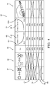
- a table 60 showing several non-limiting examples of scenarios of detection or non-detection of a tunnel 12 crossed by the vehicle 10 comprising the detection system 52 is shown. Each row of table 60 corresponds to a scenario of detection or non-detection of the crossing of vehicle 10 in a tunnel 12.
- the first column 62 represents the result of the detection by a brightness sensor of the sudden variation in brightness, passing from light to darkness or vice versa.
- a box in the first column 62 is marked by a cross, this means that there is no detection of such a variation.
- a box in the first column 62 is marked with a circle, this means that such a variation has been detected.
- the second column 64 represents the result of the detection by a rain sensor of the sudden variation of rain shower 28, from a rain shower. 28 to a situation without rain showers 28 or vice versa.
- a box in the second column 64 is marked with a cross, this means that there is no detection of such a variation.
- a box in the second column 64 is marked with a circle, this means that such a variation has been detected.
- the third column 66 indicates the minimum predetermined match threshold TH.
- the TH threshold is set at 90%.
- the TH threshold is set at 70%.
- the minimum TH match threshold is set at 60%.
- the fourth column 68 and the fifth column 70 represent levels of correspondence FL between the variation in amplitude of the radio frequency signal detected and a variation in amplitude of predetermined RS reference signals. More precisely, the fourth column 68 and the fifth column 70 respectively represent first levels of correspondence FL1 between the variation in amplitude of the radio frequency signal detected and an exponential decreasing amplitude variation 42 of a first predetermined reference signal RS1, and second levels of correspondence FL2 between the variation in amplitude of the radio frequency signal detected and an exponentially increasing variation in amplitude 46 of a second predetermined reference signal RS2. According to this example, correspondence levels of 0%, 60%, 70%, 80%, 90% and 100% will be noted.
- the second level of correspondence FL2 between the amplitude variation of the radio frequency signal detected and an increasing exponential amplitude variation 46 is 0%.
- a variation in amplitude following a decreasing exponential law of the type 'A.exp (-Bd) + C' is considered by the system of the invention as having no degree of similarity with a amplitude variation according to an increasing exponential law of the type 'A.exp (+ Bd) + C'.
- the variable 'd' of the exponential laws is representative of the distance traveled by the vehicle.
- the values A, B and C are constants depending on the nature of the tunnel and the characteristics of the radiofrequency signals.
- the sixth column 72 represents the result of the detection of a tunnel 12 crossed by the detection system 52 on board the vehicle 10. If a box in the sixth column 72 is marked with a cross, this means that it does not there was no detection. If a box is marked with a circle, then it means that there has been detection.
- the first level of correspondence FL1 between the variation in amplitude of the radio frequency signal detected and an exponential decreasing amplitude variation 42 is 0%
- the second level of correspondence FL2 between the amplitude variation of the radio frequency signal detected and an exponentially increasing amplitude variation 46 is 90%. Since the predetermined minimum correspondence threshold TH has been set at 90%, then the detection system 52 concludes with a detection of a tunnel 12 crossed by the vehicle 10, more particularly with the detection of the passage of the vehicle 10 in the exit 16 tunnel 12.
- the first level of correspondence FL1 between the variation in amplitude of the radio frequency signal detected and an exponential decreasing amplitude variation 42 is 70% and the second level of correspondence FL2 between the amplitude variation of the detected radiofrequency signal and an amplitude variation exponentially increasing 46 is 0%. Since the predetermined minimum correspondence threshold TH has been set at 70%, then the system concludes with a detection of a tunnel 12 crossed by the vehicle 10, more particularly with the detection of the passage of the vehicle 10 into the entrance 14 of the tunnel. 12.
- the first level of correspondence FL1 between the variation in amplitude of the radio frequency signal detected and an exponential decreasing amplitude variation 42 is 60% and the second level of correspondence FL2 between the variation d
- the amplitude of the radio frequency signal detected and an exponentially increasing amplitude variation 46 is 0%. Since the predetermined minimum correspondence threshold TH has been set at 70%, then the system concludes that a tunnel 12 crossed by the vehicle 10 has not been detected.
- the detection system 52 concludes with a detection of a tunnel 12 crossed by the vehicle 10 and more particularly with the detection of the passage of the vehicle 10 in the exit 16 of the tunnel 12.
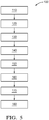
- a method 100 for detecting a tunnel 12 by a motor vehicle 10 comprises a first step consisting in receiving 110 a radiofrequency signal originating from a source external to the vehicle 10.
- the second step is a step 120 of detecting the variation in amplitude of the radiofrequency signal received.
- the next step consists in determining at least one level of correspondence FL representative of the difference between the variation in amplitude detected of the radiofrequency signal received and at least one variation of amplitude of the predetermined reference signal RS representative of the variation in amplitude signal received when crossing the vehicle 10 in a tunnel 12.
- this step can consist of two steps: a first step of determining 130 a first correspondence level FL1 representative of the difference between the detected amplitude variation of the radiofrequency signal and a predetermined exponential decreasing amplitude variation 42 representative of the passage of the system 52 in an entrance 14 of tunnel 12; and a second step of determining 140 of a second level of correspondence FL2 representative of the difference between the detected amplitude variation of the radiofrequency signal and a predetermined exponential increasing amplitude variation 46 representative of the passage of the system 52 in an output 16 of tunnel 12.
- the next step is an optional step 150 of detecting variations in meteorological conditions, such as for example a sudden variation in rainfall 28 or in brightness. This step of detecting variations in meteorological conditions allows a step 160 of adjusting a predetermined minimum correspondence threshold TH.
- the next step consists in comparing 170 the determined correspondence levels FL1, FL2 with the minimum predetermined correspondence threshold TH.
- the last step consists in detecting 180 the tunnel 12 crossed by the vehicle 10 when at least one determined level of correspondence FL1, FL2 is greater than or equal to the minimum predetermined correspondence threshold TH.
- the method 100 for detecting a tunnel 12 by a motor vehicle 10 described above can form part of a method for activating an automatic emergency braking function 57 of a vehicle 10. so that when a tunnel crossed by the vehicle 10 is detected, the detection system 52 authorizes the automatic emergency braking function 57.
Landscapes
- Engineering & Computer Science (AREA)
- Remote Sensing (AREA)
- Radar, Positioning & Navigation (AREA)
- Physics & Mathematics (AREA)
- General Physics & Mathematics (AREA)
- Computer Networks & Wireless Communication (AREA)
- Chemical & Material Sciences (AREA)
- Analytical Chemistry (AREA)
- Toxicology (AREA)
- Automation & Control Theory (AREA)
- Mathematical Physics (AREA)
- Transportation (AREA)
- Mechanical Engineering (AREA)
- Health & Medical Sciences (AREA)
- Traffic Control Systems (AREA)
- Control Of Driving Devices And Active Controlling Of Vehicle (AREA)
- Electric Propulsion And Braking For Vehicles (AREA)
Claims (6)
- System zum Detektieren (52) eines Tunnels (12) für ein Kraftfahrzeug (10), umfassend
einen Radiofrequenzsignal-Empfänger (30), der vorgesehen ist, ein Radiofrequenzsignal von einer externen Quelle des Fahrzeugs (10) zu empfangen;
einen Controller (54), der mit dem Radiofrequenzsignal-Empfänger (30) kommuniziert, wobei der Controller (54) ausgelegt ist, um mindestens eine Amplitudenvariation des von dem Empfänger (30) empfangenen Radiofrequenzsignals zu ermitteln;
dadurch gekennzeichnet, dass
das System zum Detektieren (52) eines Tunnels (12) mindestens einen Sensor (32) mindestens einer meteorologischen Bedingung, vorzugsweise einen Lichtstärkesensor, umfasst;
der Controller (54) ausgelegt ist, um mindestens ein Übereinstimmungsniveau (FL) zu bestimmen, das für die Differenz zwischen der ermittelten Amplitudenvariation des Radiofrequenzsignals und mindestens einer vorbestimmten Referenzsignal-Amplitudenvariation (RS) repräsentativ ist, die für die Amplitudenvariation eines von dem Empfänger (30) empfangenen Signals bei einer Durchquerung des Empfängers (30) eines Tunnels (12) repräsentativ ist;
der Controller (54) ausgelegt ist, um das bestimmte Übereinstimmungsniveau (FL) mit einem vorbestimmten Mindest-Übereinstimmungsgrenzwert (TH) zu vergleichen;
und dass der Controller (54) ausgelegt ist, um den von dem Detektionssystem (52) durchquerten Tunnel (12) zu ermitteln, wenn das bestimmte Übereinstimmungsniveau (FL) größer oder gleich dem vorbestimmten Mindest-Übereinstimmungsgrenzwert (TH) ist;
der Controller (54) ausgelegt ist, um mindestens eine Variation einer meteorologischen Bedingung zu ermitteln;
der Controller (54) ausgelegt ist, um den vorbestimmten Mindest-Übereinstimmungsgrenzwert (TH) an die ermittelte Variation einer meteorologischen Bedingung anzupassen. - Detektionssystem (52) eines Tunnels (12) nach Anspruch 1, dadurch gekennzeichnet, dass der Radiofrequenzsignal-Empfänger (30) ein Satelliten-Geolokalisierungssystem (GPS) umfasst.
- Detektionssystem (52) eines Tunnels (12) nach einem der vorangehenden Ansprüche, dadurch gekennzeichnet, dass die vorbestimmte Referenzsignal-Amplitudenvariation (RS) eine exponentiell abnehmende (42) oder exponentiell zunehmende (46) Amplitudenvariation umfasst, die jeweils für das Passieren des Empfängers eines Eingangs (14) eines Tunnels (12) oder eines Ausgangs (16) eines Tunnels (12) derart repräsentativ ist, dass der von dem Detektionssystem (52) durchquerte Tunnel (12) ermittelbar ist.
- Kraftfahrzeug (10), dadurch gekennzeichnet, dass es das Detektionssystem eines Tunnels (12) nach einem der vorangehenden Ansprüche umfasst.
- Methode (100) zum Detektieren eines Tunnels (12) durch ein Kraftfahrzeug (10), umfassend das Detektionssystem (52) nach einem der Ansprüche 1 bis 3, umfassend die folgenden Schritte
Empfangen (110) eines Radiofrequenzsignals von einer externen Quelle des Fahrzeugs (10);
Ermitteln (120) einer Amplitudenvariation des empfangenen Radiofrequenzsignals;
Bestimmen (130, 140) mindestens eines Übereinstimmungsniveaus (FL), das für die Differenz zwischen der ermittelten Amplitudenvariation des Radiofrequenzsignals und mindestens einer vorbestimmten Referenzsignal-Amplitudenvariation (RS) repräsentativ ist, die für die Amplitudenvariation eines empfangenen Signals bei einer Durchquerung des Empfängers (10) eines Tunnels (12) repräsentativ ist;
Vergleichen (170) des bestimmten Übereinstimmungsniveaus (FL) mit einem vorbestimmten Mindest-Übereinstimmungsgrenzwert (TH) ;
Ermitteln (180) des von dem Fahrzeug (10) durchquerten Tunnels (12), wenn das bestimmte Übereinstimmungsniveau (FL) größer oder gleich dem vorbestimmten Mindest-Übereinstimmungsgrenzwert (TH) ist;
wobei der Vergleichsschritt (170) des bestimmten Übereinstimmungsniveaus (FL) mit einem vorbestimmten Mindest-Übereinstimmungsgrenzwert (TH) zuvor die folgenden Schritte umfasst:Ermitteln (150) einer Variation meteorologischer Bedingungen;Anpassen (160) des vorbestimmten Mindest-Übereinstimmungsgrenzwerts (TH) an die ermittelte Variation einer meteorologischen Bedingung. - Detektionsmethode (100) nach vorangehendem Anspruch, dadurch gekennzeichnet, dass der Schritt des Bestimmens (130, 140) mindestens eines Übereinstimmungsniveaus einen Schritt des Bestimmens (130, 140) mindestens eines Übereinstimmungsniveaus (FL) umfasst, das für die Differenz zwischen der ermittelten Amplitudenvariation des Radiofrequenzsignals und einer vorbestimmten exponentiell abnehmenden (42) oder exponentiell zunehmenden (46) Amplitudenvariation repräsentativ ist, die jeweils für die Durchquerung des Empfänger (30) eines Eingang (14) eines Tunnels (12) oder eines Ausgang (16) eines Tunnels (12) repräsentativ ist.
Applications Claiming Priority (1)
| Application Number | Priority Date | Filing Date | Title |
|---|---|---|---|
| FR1851283A FR3077885B1 (fr) | 2018-02-15 | 2018-02-15 | Systeme et methode de detection de tunnel pour vehicule automobile |
Publications (2)
| Publication Number | Publication Date |
|---|---|
| EP3528009A1 EP3528009A1 (de) | 2019-08-21 |
| EP3528009B1 true EP3528009B1 (de) | 2020-11-18 |
Family
ID=62597614
Family Applications (1)
| Application Number | Title | Priority Date | Filing Date |
|---|---|---|---|
| EP19154233.1A Active EP3528009B1 (de) | 2018-02-15 | 2019-01-29 | System und verfahren zum deketieren eines tunnels für ein fahrzeug |
Country Status (4)
| Country | Link |
|---|---|
| US (1) | US10520603B2 (de) |
| EP (1) | EP3528009B1 (de) |
| CN (1) | CN110155063B (de) |
| FR (1) | FR3077885B1 (de) |
Families Citing this family (5)
| Publication number | Priority date | Publication date | Assignee | Title |
|---|---|---|---|---|
| JP7375678B2 (ja) * | 2020-06-02 | 2023-11-08 | トヨタ自動車株式会社 | 車両制御方法、車両制御プログラム、及び車両制御システム |
| JP2022028553A (ja) * | 2020-08-03 | 2022-02-16 | トヨタ自動車株式会社 | サーバ、プログラム、通信装置、及び車両 |
| DE102020211117A1 (de) | 2020-09-03 | 2022-03-03 | Bombardier Transportation Gmbh | Verfahren zur Detektion einer Tunneleinfahrt oder einer Tunnelausfahrt eines Schienenfahrzeugs, Betriebsverfahren sowie Schienenfahrzeug |
| JP7128875B2 (ja) * | 2020-09-29 | 2022-08-31 | 智子 藤原 | 事故防止のためのトンネル安全システム |
| CN119071736B (zh) * | 2024-07-30 | 2025-10-28 | 华中科技大学 | 基于gnss信号的无线感知方法及系统 |
Family Cites Families (8)
| Publication number | Priority date | Publication date | Assignee | Title |
|---|---|---|---|---|
| DE10320744B3 (de) * | 2003-05-09 | 2004-12-09 | Daimlerchrysler Ag | Vorrichtung und Verfahren zur Klimaregelung |
| EP1853878A2 (de) * | 2005-02-07 | 2007-11-14 | Siemens VDO Automotive Corporation | Navigationssystem |
| US8957769B2 (en) * | 2009-01-30 | 2015-02-17 | Panasonic Automotive Systems Company Of America, Division Of Panasonic Corporation Of North America | Method for driver personalization based on tunnel detection for a single-tuner system |
| US10171609B2 (en) * | 2014-04-15 | 2019-01-01 | International Business Machines Corporation | Constraint based signal for intellegent and optimized end user mobile experience enhancement |
| DE102015016045B8 (de) * | 2015-12-11 | 2017-09-14 | Audi Ag | Satellitengestützte Ermittlung eines Kraftfahrzeugs in einem überdachten Bereich |
| DE102016213913A1 (de) * | 2016-07-28 | 2018-02-01 | Robert Bosch Gmbh | Sensorvorrichtung für ein Fahrzeug, Fahrzeug, Verfahren zum Betreiben einer Sensorvorrichtung |
| JP6705335B2 (ja) * | 2016-08-11 | 2020-06-03 | 株式会社デンソー | 車両用表示制御装置及び車両運転アシストシステム |
| JP6627127B2 (ja) * | 2017-11-27 | 2020-01-08 | 本田技研工業株式会社 | 車両制御装置、車両制御方法、およびプログラム |
-
2018
- 2018-02-15 FR FR1851283A patent/FR3077885B1/fr active Active
-
2019
- 2019-01-29 EP EP19154233.1A patent/EP3528009B1/de active Active
- 2019-02-01 US US16/265,003 patent/US10520603B2/en active Active
- 2019-02-13 CN CN201910112269.1A patent/CN110155063B/zh active Active
Non-Patent Citations (1)
| Title |
|---|
| None * |
Also Published As
| Publication number | Publication date |
|---|---|
| US10520603B2 (en) | 2019-12-31 |
| EP3528009A1 (de) | 2019-08-21 |
| CN110155063B (zh) | 2022-05-17 |
| US20190250280A1 (en) | 2019-08-15 |
| FR3077885A1 (fr) | 2019-08-16 |
| FR3077885B1 (fr) | 2020-08-28 |
| CN110155063A (zh) | 2019-08-23 |
Similar Documents
| Publication | Publication Date | Title |
|---|---|---|
| EP3528009B1 (de) | System und verfahren zum deketieren eines tunnels für ein fahrzeug | |
| JP6956121B2 (ja) | 気象検出用レーダおよび車両システムの動的制御ならびに作動 | |
| US9799219B2 (en) | Vehicle data system and method | |
| EP0902877B1 (de) | Verfahren zur seitlichen vermeidung einer beweglichen zone eines fahrzeugs | |
| JP6512873B2 (ja) | ソナーセンサシステム用感度変更装置 | |
| FR2864675A1 (fr) | Appareil et procede d'assistance a la conduite d'un vehicule | |
| CN209248021U (zh) | 用于车辆的雾检测的检测设备 | |
| EP3948820B1 (de) | Verfahren zur gewährleistung, dass ein fahrzeug eine ampel sicher passieren kann, und entsprechendes computerprogrammprodukt | |
| WO2020016150A1 (fr) | Procédé de localisation d'un véhicule | |
| EP1422663B1 (de) | Verfahren und Anordnung zur Bestimmung der Sichtweite eines Fahrzeuglenkers | |
| CN117601803A (zh) | 自动雨水响应系统 | |
| US20240402295A1 (en) | Radar blindness and blockage detector, radar detector system, driver assistance system and method for detecting radar blindness and blockage | |
| FR3047217B1 (fr) | Dispositif de determination de l'etat d'un feu de signalisation, systeme embatque comprenant un tel dispositif, vehicule comprenant un tel systeme et procede de determination associe | |
| WO2008152231A2 (fr) | Procédé et dispositif de surveillance d'une position horizontale d'un avion roulant au sol | |
| WO2020260225A1 (fr) | Dispositif lumineux de vehicule automobile integrant un système de detection | |
| WO2022152986A1 (fr) | Procédé et dispositif de suivi de trajectoire d'un véhicule circulant sur une voie de circulation | |
| FR3144890A1 (fr) | Procédé et dispositif de détermination d’une direction de circulation d’un véhicule d’urgence | |
| WO2024003473A1 (fr) | Procédé et dispositif de contrôle d'un système d'aide à la conduite d'un véhicule circulant dans un environnement routier comprenant une intersection | |
| JP2005253233A (ja) | 受信異常判定装置および無線信号受信システム、無線通信システム | |
| FR3097513A1 (fr) | Procédé et dispositif de contrôle d’un véhicule automobile | |
| FR3061104A1 (fr) | Procede de localisation de zones de transmission deficiente entre une unite roue d'une roue de vehicule automobile et une unite centrale de controle des roues | |
| FR3034205A1 (fr) | Procede de suivi du comportement d’un vehicule circulant sur un reseau routier multivoies |
Legal Events
| Date | Code | Title | Description |
|---|---|---|---|
| PUAI | Public reference made under article 153(3) epc to a published international application that has entered the european phase |
Free format text: ORIGINAL CODE: 0009012 |
|
| STAA | Information on the status of an ep patent application or granted ep patent |
Free format text: STATUS: THE APPLICATION HAS BEEN PUBLISHED |
|
| AK | Designated contracting states |
Kind code of ref document: A1 Designated state(s): AL AT BE BG CH CY CZ DE DK EE ES FI FR GB GR HR HU IE IS IT LI LT LU LV MC MK MT NL NO PL PT RO RS SE SI SK SM TR |
|
| AX | Request for extension of the european patent |
Extension state: BA ME |
|
| STAA | Information on the status of an ep patent application or granted ep patent |
Free format text: STATUS: REQUEST FOR EXAMINATION WAS MADE |
|
| 17P | Request for examination filed |
Effective date: 20200210 |
|
| RBV | Designated contracting states (corrected) |
Designated state(s): AL AT BE BG CH CY CZ DE DK EE ES FI FR GB GR HR HU IE IS IT LI LT LU LV MC MK MT NL NO PL PT RO RS SE SI SK SM TR |
|
| RIN1 | Information on inventor provided before grant (corrected) |
Inventor name: NARULA, PRASANT J. Inventor name: STATNIKOV, KONSTANTIN |
|
| GRAP | Despatch of communication of intention to grant a patent |
Free format text: ORIGINAL CODE: EPIDOSNIGR1 |
|
| STAA | Information on the status of an ep patent application or granted ep patent |
Free format text: STATUS: GRANT OF PATENT IS INTENDED |
|
| RIC1 | Information provided on ipc code assigned before grant |
Ipc: G01S 19/14 20100101AFI20200526BHEP Ipc: G01S 19/42 20100101ALI20200526BHEP |
|
| INTG | Intention to grant announced |
Effective date: 20200615 |
|
| GRAS | Grant fee paid |
Free format text: ORIGINAL CODE: EPIDOSNIGR3 |
|
| GRAA | (expected) grant |
Free format text: ORIGINAL CODE: 0009210 |
|
| STAA | Information on the status of an ep patent application or granted ep patent |
Free format text: STATUS: THE PATENT HAS BEEN GRANTED |
|
| AK | Designated contracting states |
Kind code of ref document: B1 Designated state(s): AL AT BE BG CH CY CZ DE DK EE ES FI FR GB GR HR HU IE IS IT LI LT LU LV MC MK MT NL NO PL PT RO RS SE SI SK SM TR |
|
| REG | Reference to a national code |
Ref country code: GB Ref legal event code: FG4D Free format text: NOT ENGLISH |
|
| REG | Reference to a national code |
Ref country code: CH Ref legal event code: EP |
|
| REG | Reference to a national code |
Ref country code: IE Ref legal event code: FG4D Free format text: LANGUAGE OF EP DOCUMENT: FRENCH |
|
| REG | Reference to a national code |
Ref country code: DE Ref legal event code: R096 Ref document number: 602019001314 Country of ref document: DE |
|
| REG | Reference to a national code |
Ref country code: AT Ref legal event code: REF Ref document number: 1336360 Country of ref document: AT Kind code of ref document: T Effective date: 20201215 |
|
| REG | Reference to a national code |
Ref country code: AT Ref legal event code: MK05 Ref document number: 1336360 Country of ref document: AT Kind code of ref document: T Effective date: 20201118 |
|
| REG | Reference to a national code |
Ref country code: NL Ref legal event code: MP Effective date: 20201118 |
|
| PG25 | Lapsed in a contracting state [announced via postgrant information from national office to epo] |
Ref country code: RS Free format text: LAPSE BECAUSE OF FAILURE TO SUBMIT A TRANSLATION OF THE DESCRIPTION OR TO PAY THE FEE WITHIN THE PRESCRIBED TIME-LIMIT Effective date: 20201118 Ref country code: PT Free format text: LAPSE BECAUSE OF FAILURE TO SUBMIT A TRANSLATION OF THE DESCRIPTION OR TO PAY THE FEE WITHIN THE PRESCRIBED TIME-LIMIT Effective date: 20210318 Ref country code: FI Free format text: LAPSE BECAUSE OF FAILURE TO SUBMIT A TRANSLATION OF THE DESCRIPTION OR TO PAY THE FEE WITHIN THE PRESCRIBED TIME-LIMIT Effective date: 20201118 Ref country code: GR Free format text: LAPSE BECAUSE OF FAILURE TO SUBMIT A TRANSLATION OF THE DESCRIPTION OR TO PAY THE FEE WITHIN THE PRESCRIBED TIME-LIMIT Effective date: 20210219 Ref country code: NO Free format text: LAPSE BECAUSE OF FAILURE TO SUBMIT A TRANSLATION OF THE DESCRIPTION OR TO PAY THE FEE WITHIN THE PRESCRIBED TIME-LIMIT Effective date: 20210218 |
|
| PG25 | Lapsed in a contracting state [announced via postgrant information from national office to epo] |
Ref country code: AT Free format text: LAPSE BECAUSE OF FAILURE TO SUBMIT A TRANSLATION OF THE DESCRIPTION OR TO PAY THE FEE WITHIN THE PRESCRIBED TIME-LIMIT Effective date: 20201118 Ref country code: SE Free format text: LAPSE BECAUSE OF FAILURE TO SUBMIT A TRANSLATION OF THE DESCRIPTION OR TO PAY THE FEE WITHIN THE PRESCRIBED TIME-LIMIT Effective date: 20201118 Ref country code: PL Free format text: LAPSE BECAUSE OF FAILURE TO SUBMIT A TRANSLATION OF THE DESCRIPTION OR TO PAY THE FEE WITHIN THE PRESCRIBED TIME-LIMIT Effective date: 20201118 Ref country code: IS Free format text: LAPSE BECAUSE OF FAILURE TO SUBMIT A TRANSLATION OF THE DESCRIPTION OR TO PAY THE FEE WITHIN THE PRESCRIBED TIME-LIMIT Effective date: 20210318 Ref country code: LV Free format text: LAPSE BECAUSE OF FAILURE TO SUBMIT A TRANSLATION OF THE DESCRIPTION OR TO PAY THE FEE WITHIN THE PRESCRIBED TIME-LIMIT Effective date: 20201118 Ref country code: BG Free format text: LAPSE BECAUSE OF FAILURE TO SUBMIT A TRANSLATION OF THE DESCRIPTION OR TO PAY THE FEE WITHIN THE PRESCRIBED TIME-LIMIT Effective date: 20210218 |
|
| REG | Reference to a national code |
Ref country code: LT Ref legal event code: MG9D |
|
| PG25 | Lapsed in a contracting state [announced via postgrant information from national office to epo] |
Ref country code: HR Free format text: LAPSE BECAUSE OF FAILURE TO SUBMIT A TRANSLATION OF THE DESCRIPTION OR TO PAY THE FEE WITHIN THE PRESCRIBED TIME-LIMIT Effective date: 20201118 |
|
| PG25 | Lapsed in a contracting state [announced via postgrant information from national office to epo] |
Ref country code: SM Free format text: LAPSE BECAUSE OF FAILURE TO SUBMIT A TRANSLATION OF THE DESCRIPTION OR TO PAY THE FEE WITHIN THE PRESCRIBED TIME-LIMIT Effective date: 20201118 Ref country code: SK Free format text: LAPSE BECAUSE OF FAILURE TO SUBMIT A TRANSLATION OF THE DESCRIPTION OR TO PAY THE FEE WITHIN THE PRESCRIBED TIME-LIMIT Effective date: 20201118 Ref country code: EE Free format text: LAPSE BECAUSE OF FAILURE TO SUBMIT A TRANSLATION OF THE DESCRIPTION OR TO PAY THE FEE WITHIN THE PRESCRIBED TIME-LIMIT Effective date: 20201118 Ref country code: CZ Free format text: LAPSE BECAUSE OF FAILURE TO SUBMIT A TRANSLATION OF THE DESCRIPTION OR TO PAY THE FEE WITHIN THE PRESCRIBED TIME-LIMIT Effective date: 20201118 Ref country code: RO Free format text: LAPSE BECAUSE OF FAILURE TO SUBMIT A TRANSLATION OF THE DESCRIPTION OR TO PAY THE FEE WITHIN THE PRESCRIBED TIME-LIMIT Effective date: 20201118 Ref country code: LT Free format text: LAPSE BECAUSE OF FAILURE TO SUBMIT A TRANSLATION OF THE DESCRIPTION OR TO PAY THE FEE WITHIN THE PRESCRIBED TIME-LIMIT Effective date: 20201118 |
|
| REG | Reference to a national code |
Ref country code: DE Ref legal event code: R097 Ref document number: 602019001314 Country of ref document: DE |
|
| PG25 | Lapsed in a contracting state [announced via postgrant information from national office to epo] |
Ref country code: DK Free format text: LAPSE BECAUSE OF FAILURE TO SUBMIT A TRANSLATION OF THE DESCRIPTION OR TO PAY THE FEE WITHIN THE PRESCRIBED TIME-LIMIT Effective date: 20201118 Ref country code: MC Free format text: LAPSE BECAUSE OF FAILURE TO SUBMIT A TRANSLATION OF THE DESCRIPTION OR TO PAY THE FEE WITHIN THE PRESCRIBED TIME-LIMIT Effective date: 20201118 |
|
| PLBE | No opposition filed within time limit |
Free format text: ORIGINAL CODE: 0009261 |
|
| STAA | Information on the status of an ep patent application or granted ep patent |
Free format text: STATUS: NO OPPOSITION FILED WITHIN TIME LIMIT |
|
| PG25 | Lapsed in a contracting state [announced via postgrant information from national office to epo] |
Ref country code: LU Free format text: LAPSE BECAUSE OF NON-PAYMENT OF DUE FEES Effective date: 20210129 |
|
| REG | Reference to a national code |
Ref country code: BE Ref legal event code: MM Effective date: 20210131 |
|
| 26N | No opposition filed |
Effective date: 20210819 |
|
| PG25 | Lapsed in a contracting state [announced via postgrant information from national office to epo] |
Ref country code: IT Free format text: LAPSE BECAUSE OF FAILURE TO SUBMIT A TRANSLATION OF THE DESCRIPTION OR TO PAY THE FEE WITHIN THE PRESCRIBED TIME-LIMIT Effective date: 20201118 Ref country code: FR Free format text: LAPSE BECAUSE OF NON-PAYMENT OF DUE FEES Effective date: 20210131 Ref country code: AL Free format text: LAPSE BECAUSE OF FAILURE TO SUBMIT A TRANSLATION OF THE DESCRIPTION OR TO PAY THE FEE WITHIN THE PRESCRIBED TIME-LIMIT Effective date: 20201118 Ref country code: NL Free format text: LAPSE BECAUSE OF FAILURE TO SUBMIT A TRANSLATION OF THE DESCRIPTION OR TO PAY THE FEE WITHIN THE PRESCRIBED TIME-LIMIT Effective date: 20201118 |
|
| PG25 | Lapsed in a contracting state [announced via postgrant information from national office to epo] |
Ref country code: SI Free format text: LAPSE BECAUSE OF FAILURE TO SUBMIT A TRANSLATION OF THE DESCRIPTION OR TO PAY THE FEE WITHIN THE PRESCRIBED TIME-LIMIT Effective date: 20201118 |
|
| PG25 | Lapsed in a contracting state [announced via postgrant information from national office to epo] |
Ref country code: IE Free format text: LAPSE BECAUSE OF NON-PAYMENT OF DUE FEES Effective date: 20210129 Ref country code: ES Free format text: LAPSE BECAUSE OF FAILURE TO SUBMIT A TRANSLATION OF THE DESCRIPTION OR TO PAY THE FEE WITHIN THE PRESCRIBED TIME-LIMIT Effective date: 20201118 |
|
| PG25 | Lapsed in a contracting state [announced via postgrant information from national office to epo] |
Ref country code: IS Free format text: LAPSE BECAUSE OF FAILURE TO SUBMIT A TRANSLATION OF THE DESCRIPTION OR TO PAY THE FEE WITHIN THE PRESCRIBED TIME-LIMIT Effective date: 20210318 |
|
| PG25 | Lapsed in a contracting state [announced via postgrant information from national office to epo] |
Ref country code: BE Free format text: LAPSE BECAUSE OF NON-PAYMENT OF DUE FEES Effective date: 20210131 |
|
| REG | Reference to a national code |
Ref country code: CH Ref legal event code: PL |
|
| PG25 | Lapsed in a contracting state [announced via postgrant information from national office to epo] |
Ref country code: LI Free format text: LAPSE BECAUSE OF NON-PAYMENT OF DUE FEES Effective date: 20220131 Ref country code: CH Free format text: LAPSE BECAUSE OF NON-PAYMENT OF DUE FEES Effective date: 20220131 |
|
| P01 | Opt-out of the competence of the unified patent court (upc) registered |
Effective date: 20230424 |
|
| PG25 | Lapsed in a contracting state [announced via postgrant information from national office to epo] |
Ref country code: CY Free format text: LAPSE BECAUSE OF FAILURE TO SUBMIT A TRANSLATION OF THE DESCRIPTION OR TO PAY THE FEE WITHIN THE PRESCRIBED TIME-LIMIT Effective date: 20201118 |
|
| PG25 | Lapsed in a contracting state [announced via postgrant information from national office to epo] |
Ref country code: HU Free format text: LAPSE BECAUSE OF FAILURE TO SUBMIT A TRANSLATION OF THE DESCRIPTION OR TO PAY THE FEE WITHIN THE PRESCRIBED TIME-LIMIT; INVALID AB INITIO Effective date: 20190129 |
|
| PG25 | Lapsed in a contracting state [announced via postgrant information from national office to epo] |
Ref country code: MK Free format text: LAPSE BECAUSE OF FAILURE TO SUBMIT A TRANSLATION OF THE DESCRIPTION OR TO PAY THE FEE WITHIN THE PRESCRIBED TIME-LIMIT Effective date: 20201118 |
|
| PG25 | Lapsed in a contracting state [announced via postgrant information from national office to epo] |
Ref country code: TR Free format text: LAPSE BECAUSE OF FAILURE TO SUBMIT A TRANSLATION OF THE DESCRIPTION OR TO PAY THE FEE WITHIN THE PRESCRIBED TIME-LIMIT Effective date: 20201118 |
|
| PG25 | Lapsed in a contracting state [announced via postgrant information from national office to epo] |
Ref country code: MT Free format text: LAPSE BECAUSE OF FAILURE TO SUBMIT A TRANSLATION OF THE DESCRIPTION OR TO PAY THE FEE WITHIN THE PRESCRIBED TIME-LIMIT Effective date: 20201118 |
|
| REG | Reference to a national code |
Ref country code: DE Ref legal event code: R081 Ref document number: 602019001314 Country of ref document: DE Owner name: APTIV TECHNOLOGIES AG, CH Free format text: FORMER OWNER: APTIV TECHNOLOGIES LIMITED, ST. MICHAEL, BB |
|
| PGFP | Annual fee paid to national office [announced via postgrant information from national office to epo] |
Ref country code: GB Payment date: 20260112 Year of fee payment: 8 |
|
| PGFP | Annual fee paid to national office [announced via postgrant information from national office to epo] |
Ref country code: DE Payment date: 20251217 Year of fee payment: 8 |