EP3527872A1 - Elektrische leuchte - Google Patents
Elektrische leuchte Download PDFInfo
- Publication number
- EP3527872A1 EP3527872A1 EP18204590.6A EP18204590A EP3527872A1 EP 3527872 A1 EP3527872 A1 EP 3527872A1 EP 18204590 A EP18204590 A EP 18204590A EP 3527872 A1 EP3527872 A1 EP 3527872A1
- Authority
- EP
- European Patent Office
- Prior art keywords
- electrical
- electric lamp
- lamp according
- housing base
- housing
- Prior art date
- Legal status (The legal status is an assumption and is not a legal conclusion. Google has not performed a legal analysis and makes no representation as to the accuracy of the status listed.)
- Granted
Links
Images

Classifications
-
- F—MECHANICAL ENGINEERING; LIGHTING; HEATING; WEAPONS; BLASTING
- F21—LIGHTING
- F21S—NON-PORTABLE LIGHTING DEVICES; SYSTEMS THEREOF; VEHICLE LIGHTING DEVICES SPECIALLY ADAPTED FOR VEHICLE EXTERIORS
- F21S8/00—Lighting devices intended for fixed installation
- F21S8/02—Lighting devices intended for fixed installation of recess-mounted type, e.g. downlighters
- F21S8/024—Lighting devices intended for fixed installation of recess-mounted type, e.g. downlighters intended to be recessed in a wall or like vertical structure, e.g. building facade
-
- F—MECHANICAL ENGINEERING; LIGHTING; HEATING; WEAPONS; BLASTING
- F21—LIGHTING
- F21V—FUNCTIONAL FEATURES OR DETAILS OF LIGHTING DEVICES OR SYSTEMS THEREOF; STRUCTURAL COMBINATIONS OF LIGHTING DEVICES WITH OTHER ARTICLES, NOT OTHERWISE PROVIDED FOR
- F21V21/00—Supporting, suspending, or attaching arrangements for lighting devices; Hand grips
- F21V21/002—Supporting, suspending, or attaching arrangements for lighting devices; Hand grips making direct electrical contact, e.g. by piercing
-
- F—MECHANICAL ENGINEERING; LIGHTING; HEATING; WEAPONS; BLASTING
- F21—LIGHTING
- F21V—FUNCTIONAL FEATURES OR DETAILS OF LIGHTING DEVICES OR SYSTEMS THEREOF; STRUCTURAL COMBINATIONS OF LIGHTING DEVICES WITH OTHER ARTICLES, NOT OTHERWISE PROVIDED FOR
- F21V21/00—Supporting, suspending, or attaching arrangements for lighting devices; Hand grips
- F21V21/14—Adjustable mountings
- F21V21/30—Pivoted housings or frames
-
- F—MECHANICAL ENGINEERING; LIGHTING; HEATING; WEAPONS; BLASTING
- F21—LIGHTING
- F21Y—INDEXING SCHEME ASSOCIATED WITH SUBCLASSES F21K, F21L, F21S and F21V, RELATING TO THE FORM OR THE KIND OF THE LIGHT SOURCES OR OF THE COLOUR OF THE LIGHT EMITTED
- F21Y2115/00—Light-generating elements of semiconductor light sources
- F21Y2115/10—Light-emitting diodes [LED]
-
- H—ELECTRICITY
- H01—ELECTRIC ELEMENTS
- H01R—ELECTRICALLY-CONDUCTIVE CONNECTIONS; STRUCTURAL ASSOCIATIONS OF A PLURALITY OF MUTUALLY-INSULATED ELECTRICAL CONNECTING ELEMENTS; COUPLING DEVICES; CURRENT COLLECTORS
- H01R13/00—Details of coupling devices of the kinds covered by groups H01R12/70 or H01R24/00 - H01R33/00
- H01R13/02—Contact members
- H01R13/22—Contacts for co-operating by abutting
- H01R13/24—Contacts for co-operating by abutting resilient; resiliently-mounted
- H01R13/2407—Contacts for co-operating by abutting resilient; resiliently-mounted characterized by the resilient means
- H01R13/2421—Contacts for co-operating by abutting resilient; resiliently-mounted characterized by the resilient means using coil springs
-
- H—ELECTRICITY
- H01—ELECTRIC ELEMENTS
- H01R—ELECTRICALLY-CONDUCTIVE CONNECTIONS; STRUCTURAL ASSOCIATIONS OF A PLURALITY OF MUTUALLY-INSULATED ELECTRICAL CONNECTING ELEMENTS; COUPLING DEVICES; CURRENT COLLECTORS
- H01R13/00—Details of coupling devices of the kinds covered by groups H01R12/70 or H01R24/00 - H01R33/00
- H01R13/62—Means for facilitating engagement or disengagement of coupling parts or for holding them in engagement
- H01R13/627—Snap or like fastening
- H01R13/6277—Snap or like fastening comprising annular latching means, e.g. ring snapping in an annular groove
-
- H—ELECTRICITY
- H01—ELECTRIC ELEMENTS
- H01R—ELECTRICALLY-CONDUCTIVE CONNECTIONS; STRUCTURAL ASSOCIATIONS OF A PLURALITY OF MUTUALLY-INSULATED ELECTRICAL CONNECTING ELEMENTS; COUPLING DEVICES; CURRENT COLLECTORS
- H01R24/00—Two-part coupling devices, or either of their cooperating parts, characterised by their overall structure
- H01R24/38—Two-part coupling devices, or either of their cooperating parts, characterised by their overall structure having concentrically or coaxially arranged contacts
Definitions
- the present invention is based on a designed according to the preamble of the main claim electrical lamp, which is provided for coupling to an existing of an insert and an essay, electrical / electronic installation device.
- the necessary for coupling such electrical lights electrical / electronic installation devices are often used in connection with an electrical installation system of a building use.
- the use of such electrical / electronic installation device is typically designed so that it can be used in a commercial installation box and attached to the associated wall and / or installation box.
- the article of such an electrical / electronic installation device usually forms not only the visible surface, but also has the specific functional components, so that associated electric lights can be properly connected.
- the intended for coupling electrical lights consist essentially of a housing assembly, in which at least one provided with light bulbs electrical Leuchtstoffleiterplatte is housed and in which several, necessary for the function, optical and electrical / electronic components are housed.
- Such electrical lights are usually intended to provide within buildings for a targeted illumination of their environment, for an illumination of directly in their environment befindlichem objects, for abuts- Ambiente- or a signaling lighting.
- Such electric lights are intended for installation on ceilings and walls of buildings.
- the electric Luminaire has, for accommodating an electrical Leuchtestoffleiterplatte and for housing the necessary for the function of optical and electrical / electronic components, a housing assembly. Housed in the housing assembly electrical Leuchtstoffleiterplatte is provided with a cable connection to allow the use of the electrical / electronic installation device connection to an electrical installation system of a building.
- the coupling point of the attachment is designed such that only lights can be coupled, which have an identically designed (spherical) housing arrangement.
- the present invention seeks to provide an electric light, which can be connected without the use of a cable connection in a particularly simple manner to an electrical installation system of a building.
- the mechanical, electrical and data coupling takes place via a hat-shaped coupling part of the housing assembly, which is dimensionally and functionally matched to a coupling device, which, designed as a cup-shaped depression, in the essay of a connected to the electrical installation system of a building electrical / electronic installation device located.
- the housing base of the electric lamp is provided with a cylindrically shaped coupling part and if the attachment as Ankoppel adopted a precisely fitting, also cylindrically shaped, cup-shaped depression is provided in which the coupling part of the electric lamp rotatably can be inserted.
- Such a configuration of the mechanical coupling, with simultaneous electrical and data coupling advantageously allows the coupled electric lamp in a particularly simple way and can be aligned by the user by twisting function optimized.
- the electrical lamp has sliding contacts, which interact contact with circularly arranged sliding tracks, which are located on a coupling conductor plate, which is arranged in the pot-shaped recess of the essay.
- the electrical lamp L has a hat-shaped coupling part 1 for coupling to a second functional module of an electrical / electronic installation device I designed as attachment A on its housing arrangement.
- the hat-shaped coupling part 1 is integrally formed on a housing base 2 of the housing assembly.
- an electrical circuit board 4 is held, on the one hand is electrically conductive with a plurality of out of the hat-shaped coupling part 1 outwardly sliding contacts 5 and the other electrically connected to a Leuchtstoffleiterplatte 7 in combination.
- the Leuchtstoffleiterplatte 7 is fixed via a screw on the outer major surface 8 of a screwed to the housing base 2 housing cover 9.
- a design cover 10 is provided, which is also fixed to the housing base 2.
- the hat-shaped coupling part 1 is integrally formed on the housing base 2.
- the hat-shaped coupling part 1 and the housing base 2 are thus made in one piece.
- the housing base 2 has a rectangular outer contour.
- a housing cover 9 is screwed to the housing base 2, which serves as a carrier for the Leuchtstoffleiterplatte 7.
- the Leuchtstoffleiterplatte 7 is equipped with several, designed as LED bulbs 6.
- the core of the Leuchtstoffleiterplatte 7 made of aluminum.
- a design cover 10 is provided which forms the shapely conclusion on the outside and with its free edge region comprises the outer contour of the rectangular housing base 2.
- Both the LED 6 designed as light bulbs and other resilient contact pins 21 are arranged on the housing cover 9 facing the printed circuit board surface of the Leuchtstoffleiterplatte 7. For the passage of light emitted by the bulbs 6 light, the housing cover 9 corresponding light passage openings. To produce an electrical connection, the further resilient contact pins 21 penetrate the outer main surface 8 of the housing cover 9 and come into contact with the contact surface on the electrical circuit board 4. In the present embodiment, four further resilient contact pins 21 are provided for contacting, which are combined to form a contact arrangement.
- the housing base 2 designed as a reflector 11 light influencing element.
- the reflector 11 has an arcuate contour and is supported on the back of correspondingly shaped, integrally on the housing base 2, webs 12 from.
- the front side of the reflector 11 faces the illuminants 6 located on the illuminant plate 7.
- the housing cover 9 is formed rectangular in the manner of a box and is provided on one of its four peripheral walls 13 with a light exit window 14, which allows a defined light emission of the generated by the bulbs 6 and redirected by the reflector 11 light.
- the light exit window 14 is associated with one of its edge surfaces directly to the reflector 11.
- the edge surface opposite this edge surface of the light exit window 14 has an integrally formed retaining rail 22, which holding interacts with appropriately designed holding areas of the housing cover 9.
- six sliding contacts 5 are provided for the production of electrical and data communications with the electrical / electronic installation device I, wherein each of the six sliding contacts 5 is formed as a resilient contact pin.
- Three sliding contacts 5 are each combined to form a contact arrangement.
- There are two contact arrangements are provided, each having three sliding contacts 5, so that a redundant contacting of three, the attachment A of the electrical / electronic installation device I existing, sliding tracks 15 is ensured (see in particular FIG. 3 ).
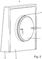
- sliding contacts 5 on the one hand fixed to the electrical circuit board 4, designed as a resilient contact pins, sliding contacts 5 on the other hand with its free end portion of the hat-shaped coupling part 1 of the housing base 2 out (see in particular FIG. 2 ).
- a counter-magnet 16 is arranged for coupling with the attachment A in the interior of the housing base 2, which holding a cooperating with a in the attachment A of the electrical / electronic installation device I - not shown for simplicity - coupling magnet cooperates.
- a circumferential outer wall of the hat-shaped coupling part 1 a circumferentially arranged, groove-shaped recess 17 is introduced, which cooperates with two locking elements 18 located in the attachment A of the electrical / electronic installation device I locking device.
- the intended for coupling with the attachment A hat-shaped coupling part 1 has in the present embodiment, a cylindrical shape.
- cup-shaped recess 19 also provided for coupling the electric lamp L, located in the article A, cup-shaped recess 19 therefore, dimensionally adapted, has a cylindrical shape.
- the two locking elements 18 partially pass through the peripheral wall 23 of the cup-shaped depression 19, which is why two slot-shaped recesses are located in the circumferential wall 23.
- the electrical / electronic installation device I consists of a housed in an installation box insert E, in the housing a plurality of electrical / electronic components are housed.
- the insert E has on the rear side connecting elements for connection to an installation system of a building.
- the front side of the insert E is provided with an electrical connector part, which is provided for connection of the wall to be arranged attachment A.
- the attachment A is provided to redeploy associated electrical lights L, wherein at the same time a mechanical, an electrical and a data-technical coupling is realized.
- the article A consists of one, the cup-shaped depression 19 having center piece Z and one, the center piece Z surrounding cover frame R.
- the mechanical, electrical and data coupling takes place via a hat-shaped coupling part 1 of the housing assembly, which is dimensionally and functionally matched to a coupling device, which, designed as a cup-shaped recess 19, in the attachment A of an electrical installation system of a building connected electrical / electronic installation device I is located.
- a coupling device which, designed as a cup-shaped recess 19, in the attachment A of an electrical installation system of a building connected electrical / electronic installation device I is located.
Landscapes
- Engineering & Computer Science (AREA)
- General Engineering & Computer Science (AREA)
- Non-Portable Lighting Devices Or Systems Thereof (AREA)
- Arrangement Of Elements, Cooling, Sealing, Or The Like Of Lighting Devices (AREA)
- Fastening Of Light Sources Or Lamp Holders (AREA)
Abstract
Description
- Die vorliegende Erfindung geht von einer gemäß Oberbegriff des Hauptanspruches konzipierten elektrischen Leuchte aus, welche zur Ankopplung an ein, aus einem Einsatz und einem Aufsatz bestehendes, elektrisches/elektronisches Installationsgerät vorgesehen ist.
- Die zur Ankopplung solcher elektrischen Leuchten notwendigen elektrischen/elektronischen Installationsgeräte finden oftmals im Zusammenhang mit einem elektrischen Installationssystem eines Gebäudes Verwendung. Der Einsatz eines solchen elektrischen/elektronischen Installationsgerätes ist typischerweise so gestaltet, dass dieser in eine handelsübliche Installationsdose eingesetzt und an der zugehörigen Wand und/oder Installationsdose befestigt werden kann. Der Aufsatz eines solchen elektrischen/elektronischen Installationsgerätes bildet in der Regel nicht nur die sichtseitige Oberfläche, sondern weist auch die spezifischen Funktionskomponenten auf, damit zugehörige elektrische Leuchten ordnungsgemäß angekoppelt werden können. Die zur Ankopplung vorgesehenen elektrischen Leuchten bestehen im Wesentlichen aus einer Gehäuseanordnung, in welcher zumindest eine mit Leuchtmitteln versehene elektrische Leuchtmittelleiterplatte untergebracht ist und in welcher mehrere, zur Funktion notwendige, optische sowie elektrische/elektronische Bauteile untergebracht sind. Derartige elektrische Leuchten sind in der Regel dafür vorgesehen, innerhalb von Gebäuden für eine gezielte Ausleuchtung ihrer Umgebung, für eine Anleuchtung von direkt in ihrer Umgebung befindlicher Gegenstände, für eine Orientierungs- Ambiente- beziehungsweise eine Signalisierungsbeleuchtung Sorge zu tragen. Beispielsweise sind solche elektrische Leuchten zur Installation an Decken und Wänden von Gebäuden vorgesehen.
- Durch die
DE 20 2017 103 604 U1 ist eine dem Oberbegriff des Hauptanspruches entsprechende elektrische Leuchte bekannt geworden, welche zur Ankopplung an ein elektrisches/elektronisches Installationsgerät vorgesehen ist. Die elektrische Leuchte weist, zur Unterbringung einer elektrischen Leuchtmittelleiterplatte und zur Unterbringung der zur Funktion notwendigen optischen sowie elektrischen/elektronischen Bauteile, eine Gehäuseanordnung auf. Die in der Gehäuseanordnung untergebrachte elektrische Leuchtmittelleiterplatte ist mit einer Kabelverbindung versehen, um über den Einsatz des elektrischen/elektronischen Installationsgerätes den Anschluss an ein elektrisches Installationssystem eines Gebäudes zu ermöglichen. Die Ankoppelstelle des Aufsatzes ist derart gestaltet, dass lediglich Leuchten angekoppelt werden können, welche eine identisch ausgeführte (kugelförmige) Gehäuseanordnung aufweisen. - Ausgehend von derart ausgebildeten elektrischen Leuchten liegt der vorliegenden Erfindung die Aufgabe zugrunde, eine elektrische Leuchte zu schaffen, welche ohne die Verwendung einer Kabelverbindung auf besonders einfache Art und Weise an ein elektrisches Installationssystem eines Gebäudes angeschlossen werden kann. Vorteilhafterweise erfolgt die mechanische, die elektrische und die datentechnische Ankopplung über ein hutförmiges Koppelteil der Gehäuseanordnung, welches maßlich und funktionstechnisch auf eine Koppeleinrichtung abgestimmt ist, die sich, ausgebildet als topfförmige Vertiefung, im Aufsatz eines an das elektrische Installationssystem eines Gebäudes angeschlossenen elektrischen/elektronischen Installationsgerätes befindet. Somit besteht lediglich die Notwendigkeit, dass die zur Ankopplung vorgesehenen elektrischen Leuchten über ein einheitliches, hutförmig ausgebildetes Koppelteil verfügen.
- Erfindungsgemäß wird diese Aufgabe durch die im Hauptanspruch angegebenen Merkmale gelöst.
- Bei einer derartigen Ausbildung von elektrischen Leuchten ist besonders vorteilhaft, wenn der Gehäusesockel der elektrischen Leuchte mit einem zylindrisch gestalteten Koppelteil versehen ist und wenn am Aufsatz als Ankoppeleinrichtung eine passgenaue, ebenfalls zylindrisch gestaltete, topfförmige Vertiefung vorgesehen ist, in welche das Koppelteil der elektrischen Leuchte drehbeweglich eingesteckt werden kann. Durch eine derartige Ausgestaltung der mechanischen Ankopplung, bei gleichzeitiger elektrischer und datentechnischer Ankopplung, wird vorteilhafter Weise ermöglicht, dass die angekoppelte elektrische Leuchte auf besonders einfache Art und Weise vom Benutzer durch Verdrehen funktionsoptimiert ausgerichtet werden kann. Dies ist auch dadurch begründet, weil die elektrische Leuchte über Schleifkontakte verfügt, die kontaktgebend mit kreisförmig angeordneten Schleifbahnen zusammenwirken, welche sich auf einer Koppelleiterplatte befinden, die in der topfförmigen Vertiefung des Aufsatzes angeordnet ist.
- Weitere vorteilhafte Ausgestaltungen des erfindungsgemäßen Gegenstandes sind in den Unteransprüchen angegeben. Anhand eines Ausführungsbeispiels sei der erfindungsgemäße Gegenstand näher beschrieben, dabei zeigen:
- Fig. 1:
- prinziphaft eine elektrische Leuchte in Explosionsdarstellung, räumlich in schräger Draufsicht;
- Fig. 2:
- prinziphaft eine elektrische Leuchte im Zusammenbau, räumlich in schräger Unteransicht;
- Fig. 3:
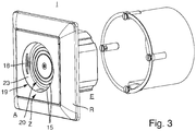
- prinziphaft ein zur Ankopplung elektrischer Leuchten vorgesehenes, aus einem Einsatz und einem Aufsatz bestehendes elektrisches/elektronisches Installationsgerät, im Zusammenbau, räumlich in schräger Draufsicht.
- Wie aus den Figuren hervorgeht, weist die elektrische Leuchte L zur Kopplung mit einem, als Aufsatz A ausgeführten zweiten Funktionsmodul eines elektrischen/elektronischen Installationsgerätes I an seiner Gehäuseanordnung ein hutförmiges Koppelteil 1 auf. Das hutförmige Koppelteil 1 ist einstückig an einen Gehäusesockel 2 der Gehäuseanordnung angeformt. Im Innenraum 3 des Gehäusesockels 2 ist eine elektrische Leiterplatte 4 gehalten, die einerseits elektrisch leitend mit mehreren, aus dem hutförmigen Koppelteil 1 nach außen geführten Schleifkontakten 5 und die andererseits elektrisch leitend mit einer Leuchtmittelleiterplatte 7 in Verbindung steht. Die Leuchtmittelleiterplatte 7 ist über eine Schraubverbindung an der äußeren Hauptfläche 8 eines an den Gehäusesockel 2 angeschraubten Gehäusedeckels 9 festgelegt. Zudem ist eine Designabdeckung 10 vorgesehen, welche ebenfalls am Gehäusesockel 2 festgelegt ist.
- Wie des Weiteren aus den Figuren hervorgeht, ist das hutförmige Koppelteil 1 an den Gehäusesockel 2 angeformt. Das hutförmige Koppelteil 1 und der Gehäusesockel 2 sind somit einstückig ausgeführt. Der Gehäusesockel 2 weist eine rechteckige Außenkontur auf. Wie bereits erwähnt, ist am Gehäusesockel 2 ein Gehäusedeckel 9 angeschraubt, welcher als Träger für die Leuchtmittelleiterplatte 7 dient. Die Leuchtmittelleiterplatte 7 ist mit mehreren, als LED ausgeführten Leuchtmitteln 6 bestückt. Um eine gute Wärmeabfuhr zu gewährleisten, besteht der Kern der Leuchtmittelleiterplatte 7 aus Aluminium. Wie ebenfalls bereits erwähnt, ist eine Designabdeckung 10 vorgesehen, welche außenseitig den formschönen Abschluss bildet und mit ihrem freien Randbereich die Außenkontur des rechteckigen Gehäusesockels 2 umfasst. Sowohl die als LED ausgeführten Leuchtmittel 6 als auch weitere federnde Kontaktstifte 21 sind an der dem Gehäusedeckel 9 zugewandten Leiterplattenfläche der Leuchtmittelleiterplatte 7 angeordnet. Für den Lichtdurchtritt des von den Leuchtmitteln 6 abgegebenen Lichtes weist der Gehäusedeckel 9 entsprechende Lichtdurchtrittsöffnungen auf. Zur Herstellung einer elektrischen Verbindung durchdringen die weiteren federnden Kontaktstifte 21 die äußere Hauptfläche 8 des Gehäusedeckels 9 und kommen kontaktgebend an, auf der elektrischen Leiterplatte 4 vorhandenen, Kontaktflächen zur Anlage. Beim vorliegenden Ausführungsbeispiel sind zur Kontaktierung vier weitere federnde Kontaktstifte 21 vorgesehen, welche zu einer Kontaktanordnung zusammengefasst sind.
- Wie insbesondere aus
Figur 1 hervorgeht, ist am Gehäusesockel 2 ein als Reflektor 11 ausgeführtes Lichtbeeinflussungselement gehalten. Der Reflektor 11 weist eine bogenförmige Kontur auf und stützt sich rückseitig an entsprechend geformten, einstückig am Gehäusesockel 2 vorhandenen, Stegen 12 ab. Die Frontseite des Reflektors 11 ist den auf der Leuchtmittelleiterplatte 7 befindlichen Leuchtmitteln 6 zugewandt. Der Gehäusedeckel 9 ist rechteckförmig in Art eines Kastens ausgebildet und ist an einer seiner vier Umfangswände 13 mit einem Lichtaustrittsfenster 14 versehen, welches einen definierten Lichtaustritt des von den Leuchtmitteln 6 erzeugten und vom Reflektor 11 umgeleiteten Lichtes ermöglicht. Das Lichtaustrittsfenster 14 ist mit einer seiner Kantenflächen direkt dem Reflektor 11 zugeordnet. Die dieser Kantenfläche gegenüberliegende Kantenfläche des Lichtaustrittsfensters 14 weist eine angeformte Halteschiene 22 auf, welche haltend mit entsprechend gestalteten Haltebereichen des Gehäusedeckels 9 zusammenwirkt. Beim vorliegenden Ausführungsbeispiel sind zur Herstellung von elektrischen und datentechnischen Verbindungen mit dem elektrischen/elektronischen Installationsgerät I sechs Schleifkontakte 5 vorgesehen, wobei jeder der sechs Schleifkontakte 5 als federnder Kontaktstift ausgebildet ist. Drei Schleifkontakte 5 sind jeweils zu einer Kontaktanordnung zusammengefasst. Es sind zwei Kontaktanordnungen vorgesehen, die jeweils drei Schleifkontakte 5 aufweisen, damit eine redundante Kontaktierung von drei, am Aufsatz A des elektrischen/elektronischen Installationsgerätes I vorhandenen, Schleifbahnen 15 gewährleistet ist (siehe insbesondereFigur 3 ). Zu diesem Zweck sind die einerseits an der elektrischen Leiterplatte 4 festgelegten, als federnde Kontaktstifte ausgeführten, Schleifkontakte 5 andererseits mit ihrem freien Endbereich aus dem hutförmigen Koppelteil 1 des Gehäusesockels 2 nach außen geführt (siehe insbesondereFigur 2 ). - Wie zudem aus den Figuren hervorgeht, ist zur Kopplung mit dem Aufsatz A im Innenraum des Gehäusesockels 2 ein Gegenmagnet 16 angeordnet, welcher haltend mit einem im Aufsatz A des elektrischen/elektronischen Installationsgeräts I befindlichen - der Einfachheit halber nicht dargestellten - Koppelmagneten zusammenwirkt. Weiterhin ist in der umfänglichen Außenwand des hutförmigen Koppelteils 1 eine umlaufend angeordnete, nutförmige Ausnehmung 17 eingebracht, welche mit zwei Riegelelementen 18 einer im Aufsatz A des elektrischen/elektronischen Installationsgerätes I befindlichen Verriegelungseinrichtung zusammenwirkt. Das zur Kopplung mit dem Aufsatz A vorgesehene hutförmige Koppelteil 1 weist beim vorliegenden Ausführungsbeispiel eine zylindrische Form auf. Auch die zur Kopplung der elektrischen Leuchte L vorgesehene, im Aufsatz A befindliche, topfförmige Vertiefung 19 weist deshalb, maßlich angepasst, eine zylindrische Form auf. Die beiden Riegelelemente 18 durchgreifen partiell die Umfangswand 23 der topfförmigen Vertiefung 19, weshalb sich in der Umfangswand 23 zwei schlitzförmige Ausnehmungen befinden.
- Wie insbesondere aus
Figur 3 hervorgeht, besteht das elektrische/elektronische Installationsgerät I aus einem in einer Installationsdose unterzubringenden Einsatz E, in dessen Gehäuse mehrere elektrische/elektronische Bauteile untergebracht sind. Der Einsatz E weist rückseitig Verbindungselemente zum Anschluss an ein Installationssystem eines Gebäudes auf. Frontseitig ist der Einsatz E mit einem elektrischen Steckerteil versehen, welches zum Anschluss des wandseitig anzuordnenden Aufsatzes A vorgesehen ist. Wie bereits beschrieben, ist der Aufsatz A dazu vorgesehen, zugehörige elektrische Leuchten L wiederlösbar anzukoppeln, wobei gleichzeitig eine mechanische, eine elektrische und eine datentechnische Ankopplung realisiert wird. Frontseitig weist der Aufsatz A dazu die topfförmige Vertiefung 19 auf, in welcher eine Koppelleiterplatte 20 angeordnet ist, die drei kreisförmig angeordnete, elektrische Schleifbahnen 15 aufweist, um eine elektrische Kontaktierung mit den sechs Schleifkontakten 5 der elektrischen Leuchte L herzustellen. Wie des Weiteren insbesondere ausFigur 3 hervorgeht, besteht der Aufsatz A aus einem, die topfförmige Vertiefung 19 aufweisenden Zentralstück Z und einem, das Zentralstück Z umgebenden Abdeckrahmen R. - Es ist somit eine elektrische Leuchte L geschaffen, welche ohne die Verwendung einer Kabelverbindung auf besonders einfache Art und Weise an ein elektrisches Installationssystem eines Gebäudes angeschlossen werden kann. Vorteilhafterweise erfolgt die mechanische, die elektrische und die datentechnische Ankopplung über ein hutförmiges Koppelteil 1 der Gehäuseanordnung, welches maßlich und funktionstechnisch auf eine Koppeleinrichtung abgestimmt ist, die sich, ausgebildet als topfförmige Vertiefung 19, im Aufsatz A eines an das elektrische Installationssystem eines Gebäudes angeschlossenen elektrischen/elektronischen Installationsgerätes I befindet. Somit besteht lediglich die Notwendigkeit, dass die zur Ankopplung vorgesehenen elektrischen Leuchten L über ein einheitliches, hutförmig ausgebildetes Koppelteil 1 verfügen.
-
- 1
- Hutförmiges Koppelteil
- 2
- Gehäusesockel
- 3
- Innenraum
- 4
- Elektrische Leiterplatte
- 5
- Schleifkontakte
- 6
- Leuchtmittel
- 7
- Leuchtmittelleiterplatte
- 8
- Äußere Hauptfläche
- 9
- Gehäusedeckel
- 10
- Designabdeckung
- 11
- Reflektor
- 12
- Stege
- 13
- Umfangswände
- 14
- Lichtaustrittsfenster
- 15
- Elektrische Schleifbahnen
- 16
- Gegenmagnet
- 17
- Nutförmige Ausnehmung
- 18
- Riegelelement
- 19
- Topfförmige Vertiefung
- 20
- Koppelleiterplatte
- 21
- Weitere federnde Kontaktstifte
- 22
- Halteschiene
- 23
- Umfangswand
- A
- Aufsatz
- E
- Einsatz
- I
- Elektrisches/elektronisches Installationsgerät
- L
- Elektrische Leuchte
- R
- Abdeckrahmen
- Z
- Zentralstück
Claims (13)
- Elektrische Leuchte mit einer Gehäuseanordnung, in welcher zumindest eine, mit zumindest einem Leuchtmittel bestückte elektrische Leuchtmittelleiterplatte untergebracht ist und in welcher mehrere zur Funktion notwendige optische sowie elektrische/elektronische Bauteile untergebracht sind, wobei die elektrische Leuchte zur Ankopplung an ein elektrisches Installationsgerät vorgesehen ist, welches aus einem an ein elektrisches Installationssystem eines Gebäudes angeschlossenen Einsatz und einem den wandseitigen Abschluss bildenden Aufsatz besteht, dadurch gekennzeichnet, dass die Gehäuseanordnung modulartig aus einem mit einem hutförmigen Koppelteil (1) versehenen Gehäusesockel (2), einem am Gehäusesockel (2) festlegbaren, als Träger für die Leuchtmittelleiterplatte (7) dienenden Gehäusedeckel (9) und einer am Gehäusesockel (2) festlegbaren Designabdeckung (10) besteht, und dass im Innenraum (3) des Gehäusesockels (2) eine elektrische Leiterplatte (4) gehalten ist, die einerseits elektrisch leitend mit mehreren aus dem hutförmigen Koppelteil (1) nach außen geführten Schleifkontakten (5) und die andererseits elektrisch leitend mit der Leuchtmittelleiterplatte (7) in Verbindung steht.
- Elektrische Leuchte nach Anspruch 1, dadurch gekennzeichnet, dass am Gehäusesockel (2) und/oder am Gehäusedeckel (9) zumindest ein Lichtbeeinflussungselement gehalten ist.
- Elektrische Leuchte nach Anspruch 2, dadurch gekennzeichnet, dass zumindest ein Lichtbeeinflussungselement als Reflektor (11) ausgeführt ist.
- Elektrische Leuchte nach einem der Ansprüche 1 bis 3, dadurch gekennzeichnet, dass am Gehäusesockel (2) und/oder am Gehäusedeckel (9) zumindest ein Lichtaustrittsfenster (14) gehalten ist.
- Elektrische Leuchte nach einem der Ansprüche 1 bis 4, dadurch gekennzeichnet, dass zumindest ein Schleifkontakt (5) als federnder Kontaktstift ausgeführt ist.
- Elektrische Leuchte nach einem der Ansprüche 1 bis 5, dadurch gekennzeichnet, dass zumindest ein Schleifkontakt (5) als federnder Vielfingerschleifer ausgeführt ist.
- Elektrische Leuchte nach einem der Ansprüche 1 bis 6, dadurch gekennzeichnet, dass die Leuchtmittelleiterplatte (7) mit mehreren weiteren federnden Kontaktstiften (21) in Verbindung steht, welche den Gehäusedeckel (9) durchdringen und kontaktgebend an der elektrischen Leiterplatte (4) zur Anlage kommen.
- Elektrische Leuchte nach einem der Ansprüche 1 bis 7, dadurch gekennzeichnet, dass drei Schleifkontakte (5) jeweils zu einer Kontaktanordnung zusammengefasst sind, und dass zwei jeweils drei Schleifkontakte (5) aufweisende Kontaktanordnungen einerseits an der elektrischen Leiterplatte (4) festgelegt sind, welche andererseits zur Kontaktierung des Aufsatzes (A) aus dem hutförmigen Koppelteil (1) des Gehäusesockels (2) nach außen geführt sind.
- Elektrische Leuchte nach einem der Ansprüche 1 bis 8, dadurch gekennzeichnet, dass zur Kopplung mit dem Aufsatz (A) im Innenraum des Gehäusesockels (2) zumindest ein Gegenmagnet (16) angeordnet ist, welcher mit einem im Aufsatz (A) des elektrischen/elektronischen Installationsgeräts (I) befindlichen Koppelmagneten zusammenwirkt.
- Elektrische Leuchte nach einem der Ansprüche 1 bis 9, dadurch gekennzeichnet, dass in der Außenwand des hutförmigen Koppelteils (1) zumindest eine, umlaufend angeordnete, nutförmige Ausnehmung (17) eingebracht ist, welche mit zumindest einem Riegelelement (18) einer im Aufsatz (A) des elektrischen/elektronischen Installationsgerätes (I) befindlichen Verriegelungseinrichtung zusammenwirkt.
- Elektrische Leuchte nach einem der Ansprüche 1 bis 10, dadurch gekennzeichnet, dass das zur Kopplung mit dem Aufsatz (A) vorgesehene hutförmige Koppelteil (1) eine zylindrische Form aufweist.
- Elektrische Leuchte nach einem der Ansprüche 1 bis 11, dadurch gekennzeichnet, dass der zur Kopplung der elektrischen Leuchte (L) vorgesehene Aufsatz (A) eine topfförmige Vertiefung (19) aufweist, welche zylindrisch ausgeführt ist.
- Elektrische Leuchte nach einem der Ansprüche 1 bis 12, dadurch gekennzeichnet, dass das hutförmige Koppelteil (1) einstückig Bestandteil des Gehäusesockels (2) ist.
Applications Claiming Priority (1)
| Application Number | Priority Date | Filing Date | Title |
|---|---|---|---|
| DE102018103381.8A DE102018103381B3 (de) | 2018-02-15 | 2018-02-15 | Elektrische Leuchte |
Publications (2)
| Publication Number | Publication Date |
|---|---|
| EP3527872A1 true EP3527872A1 (de) | 2019-08-21 |
| EP3527872B1 EP3527872B1 (de) | 2020-03-25 |
Family
ID=64267511
Family Applications (1)
| Application Number | Title | Priority Date | Filing Date |
|---|---|---|---|
| EP18204590.6A Active EP3527872B1 (de) | 2018-02-15 | 2018-11-06 | Elektrische leuchte |
Country Status (2)
| Country | Link |
|---|---|
| EP (1) | EP3527872B1 (de) |
| DE (1) | DE102018103381B3 (de) |
Citations (6)
| Publication number | Priority date | Publication date | Assignee | Title |
|---|---|---|---|---|
| US20050148241A1 (en) * | 2001-05-31 | 2005-07-07 | Ran Kohen | Quick connect device for electrical fixtures |
| US20080243003A1 (en) * | 2007-03-26 | 2008-10-02 | Liposonix, Inc. | Slip ring space and method for its use |
| EP2211084A1 (de) * | 2009-01-21 | 2010-07-28 | Abb Ag | Leuchte, insbesondere Wandleuchte |
| DE102009016778A1 (de) * | 2009-04-07 | 2011-04-07 | Abb Ag | Unterputz-LED-Leuchte |
| US20140204594A1 (en) * | 2013-01-22 | 2014-07-24 | Panasonic Corporation | Illumination light source and lighting apparatus |
| US20150085500A1 (en) * | 2013-09-23 | 2015-03-26 | Canarm Ltd. | Recessed mini-can lighting assembly |
Family Cites Families (3)
| Publication number | Priority date | Publication date | Assignee | Title |
|---|---|---|---|---|
| CN102066837B (zh) | 2008-06-17 | 2014-06-18 | 罗姆股份有限公司 | Led灯 |
| DE102014109292A1 (de) | 2014-07-03 | 2016-01-07 | Hellmann Components Ug | Einbauleuchtmelder |
| DE202017103604U1 (de) | 2016-08-19 | 2017-07-11 | Insta Gmbh | Beleuchtungseinrichtung |
-
2018
- 2018-02-15 DE DE102018103381.8A patent/DE102018103381B3/de not_active Expired - Fee Related
- 2018-11-06 EP EP18204590.6A patent/EP3527872B1/de active Active
Patent Citations (6)
| Publication number | Priority date | Publication date | Assignee | Title |
|---|---|---|---|---|
| US20050148241A1 (en) * | 2001-05-31 | 2005-07-07 | Ran Kohen | Quick connect device for electrical fixtures |
| US20080243003A1 (en) * | 2007-03-26 | 2008-10-02 | Liposonix, Inc. | Slip ring space and method for its use |
| EP2211084A1 (de) * | 2009-01-21 | 2010-07-28 | Abb Ag | Leuchte, insbesondere Wandleuchte |
| DE102009016778A1 (de) * | 2009-04-07 | 2011-04-07 | Abb Ag | Unterputz-LED-Leuchte |
| US20140204594A1 (en) * | 2013-01-22 | 2014-07-24 | Panasonic Corporation | Illumination light source and lighting apparatus |
| US20150085500A1 (en) * | 2013-09-23 | 2015-03-26 | Canarm Ltd. | Recessed mini-can lighting assembly |
Also Published As
| Publication number | Publication date |
|---|---|
| EP3527872B1 (de) | 2020-03-25 |
| DE102018103381B3 (de) | 2019-03-21 |
Similar Documents
| Publication | Publication Date | Title |
|---|---|---|
| EP1983620B1 (de) | Steckdose mit Orientierungsbeleuchtung | |
| EP3527886B1 (de) | Anordnung umfassend ein electrisches/elektrisches installationsgerät und eine electrische leuchte | |
| EP3114400B1 (de) | Leuchte bzw. beleuchtungsanordnung mit länglichem trägerelement und lösbar befestigbarem leuchtmodul | |
| DE102018101871A1 (de) | Leuchtmodulanordnung | |
| AT14620U1 (de) | Leuchte mit Trägerelement und lösbar befestigbarem Leuchtmodul | |
| EP2579398B1 (de) | Elektrische Schutzkontaktsteckdose | |
| DE202017103604U1 (de) | Beleuchtungseinrichtung | |
| DE112013000818T5 (de) | Glühlampenfassung und Beleuchtungsvorrichtung | |
| DE102016104084A1 (de) | Leuchtensystem | |
| EP3527887A1 (de) | Elektrische leuchte | |
| DE102019116093A1 (de) | Fernschaltbare Schutzkontaktsteckdose | |
| DE102007045869B3 (de) | Elektrisches/elektronisches Installationsgerät | |
| DE102018103381B3 (de) | Elektrische Leuchte | |
| DE102019134853A1 (de) | Elektrisches/elektronisches Gerät | |
| DE102016111959B3 (de) | Elektrische Schutzkontaktsteckdose | |
| DE10334247B3 (de) | Elektrische Schutzkontaktsteckdose | |
| DE102009031588B4 (de) | Elektrische Steckvorrichtung | |
| EP3527885B1 (de) | Anordnung umfassend ein elektrisches/elektronisches installationsgerät und eine elektrische leuchte | |
| EP3396234B1 (de) | Beleuchtungseinrichtung | |
| EP1988615B1 (de) | Unterputz-Steckdose mit Leuchtmittelmodul | |
| EP1758214B1 (de) | Anordnung mit Leistungshalbleitermodul und mit Anschlussverbinder | |
| DE4445164C2 (de) | Sicherheits- und Rettungszeichenleuchte | |
| EP3805639B1 (de) | Leuchte mit steckkontakt, verwendung einer solchen leuchte und steckverbinder für eine solche leuchte | |
| DE2261106A1 (de) | Elektrische baugruppe mit einem gehaeuse | |
| DE102016111956B3 (de) | Elektrisches/elektronisches Gerät |
Legal Events
| Date | Code | Title | Description |
|---|---|---|---|
| PUAI | Public reference made under article 153(3) epc to a published international application that has entered the european phase |
Free format text: ORIGINAL CODE: 0009012 |
|
| STAA | Information on the status of an ep patent application or granted ep patent |
Free format text: STATUS: THE APPLICATION HAS BEEN PUBLISHED |
|
| AK | Designated contracting states |
Kind code of ref document: A1 Designated state(s): AL AT BE BG CH CY CZ DE DK EE ES FI FR GB GR HR HU IE IS IT LI LT LU LV MC MK MT NL NO PL PT RO RS SE SI SK SM TR |
|
| AX | Request for extension of the european patent |
Extension state: BA ME |
|
| STAA | Information on the status of an ep patent application or granted ep patent |
Free format text: STATUS: REQUEST FOR EXAMINATION WAS MADE |
|
| 17P | Request for examination filed |
Effective date: 20190910 |
|
| RBV | Designated contracting states (corrected) |
Designated state(s): AL AT BE BG CH CY CZ DE DK EE ES FI FR GB GR HR HU IE IS IT LI LT LU LV MC MK MT NL NO PL PT RO RS SE SI SK SM TR |
|
| GRAP | Despatch of communication of intention to grant a patent |
Free format text: ORIGINAL CODE: EPIDOSNIGR1 |
|
| STAA | Information on the status of an ep patent application or granted ep patent |
Free format text: STATUS: GRANT OF PATENT IS INTENDED |
|
| RIC1 | Information provided on ipc code assigned before grant |
Ipc: H01R 13/24 20060101ALN20191129BHEP Ipc: H01R 24/38 20110101ALN20191129BHEP Ipc: F21V 21/002 20060101ALI20191129BHEP Ipc: H01R 13/627 20060101ALN20191129BHEP Ipc: F21V 21/30 20060101ALI20191129BHEP Ipc: F21Y 115/10 20160101ALN20191129BHEP Ipc: F21S 8/02 20060101AFI20191129BHEP |
|
| INTG | Intention to grant announced |
Effective date: 20200107 |
|
| GRAS | Grant fee paid |
Free format text: ORIGINAL CODE: EPIDOSNIGR3 |
|
| GRAA | (expected) grant |
Free format text: ORIGINAL CODE: 0009210 |
|
| STAA | Information on the status of an ep patent application or granted ep patent |
Free format text: STATUS: THE PATENT HAS BEEN GRANTED |
|
| AK | Designated contracting states |
Kind code of ref document: B1 Designated state(s): AL AT BE BG CH CY CZ DE DK EE ES FI FR GB GR HR HU IE IS IT LI LT LU LV MC MK MT NL NO PL PT RO RS SE SI SK SM TR |
|
| REG | Reference to a national code |
Ref country code: GB Ref legal event code: FG4D Free format text: NOT ENGLISH |
|
| REG | Reference to a national code |
Ref country code: DE Ref legal event code: R096 Ref document number: 502018001034 Country of ref document: DE |
|
| REG | Reference to a national code |
Ref country code: AT Ref legal event code: REF Ref document number: 1248962 Country of ref document: AT Kind code of ref document: T Effective date: 20200415 Ref country code: NL Ref legal event code: FP Ref country code: IE Ref legal event code: FG4D Free format text: LANGUAGE OF EP DOCUMENT: GERMAN |
|
| REG | Reference to a national code |
Ref country code: SE Ref legal event code: TRGR |
|
| PG25 | Lapsed in a contracting state [announced via postgrant information from national office to epo] |
Ref country code: RS Free format text: LAPSE BECAUSE OF FAILURE TO SUBMIT A TRANSLATION OF THE DESCRIPTION OR TO PAY THE FEE WITHIN THE PRESCRIBED TIME-LIMIT Effective date: 20200325 Ref country code: NO Free format text: LAPSE BECAUSE OF FAILURE TO SUBMIT A TRANSLATION OF THE DESCRIPTION OR TO PAY THE FEE WITHIN THE PRESCRIBED TIME-LIMIT Effective date: 20200625 Ref country code: FI Free format text: LAPSE BECAUSE OF FAILURE TO SUBMIT A TRANSLATION OF THE DESCRIPTION OR TO PAY THE FEE WITHIN THE PRESCRIBED TIME-LIMIT Effective date: 20200325 |
|
| PG25 | Lapsed in a contracting state [announced via postgrant information from national office to epo] |
Ref country code: BG Free format text: LAPSE BECAUSE OF FAILURE TO SUBMIT A TRANSLATION OF THE DESCRIPTION OR TO PAY THE FEE WITHIN THE PRESCRIBED TIME-LIMIT Effective date: 20200625 Ref country code: LV Free format text: LAPSE BECAUSE OF FAILURE TO SUBMIT A TRANSLATION OF THE DESCRIPTION OR TO PAY THE FEE WITHIN THE PRESCRIBED TIME-LIMIT Effective date: 20200325 Ref country code: HR Free format text: LAPSE BECAUSE OF FAILURE TO SUBMIT A TRANSLATION OF THE DESCRIPTION OR TO PAY THE FEE WITHIN THE PRESCRIBED TIME-LIMIT Effective date: 20200325 Ref country code: GR Free format text: LAPSE BECAUSE OF FAILURE TO SUBMIT A TRANSLATION OF THE DESCRIPTION OR TO PAY THE FEE WITHIN THE PRESCRIBED TIME-LIMIT Effective date: 20200626 |
|
| REG | Reference to a national code |
Ref country code: LT Ref legal event code: MG4D |
|
| PG25 | Lapsed in a contracting state [announced via postgrant information from national office to epo] |
Ref country code: SK Free format text: LAPSE BECAUSE OF FAILURE TO SUBMIT A TRANSLATION OF THE DESCRIPTION OR TO PAY THE FEE WITHIN THE PRESCRIBED TIME-LIMIT Effective date: 20200325 Ref country code: RO Free format text: LAPSE BECAUSE OF FAILURE TO SUBMIT A TRANSLATION OF THE DESCRIPTION OR TO PAY THE FEE WITHIN THE PRESCRIBED TIME-LIMIT Effective date: 20200325 Ref country code: LT Free format text: LAPSE BECAUSE OF FAILURE TO SUBMIT A TRANSLATION OF THE DESCRIPTION OR TO PAY THE FEE WITHIN THE PRESCRIBED TIME-LIMIT Effective date: 20200325 Ref country code: EE Free format text: LAPSE BECAUSE OF FAILURE TO SUBMIT A TRANSLATION OF THE DESCRIPTION OR TO PAY THE FEE WITHIN THE PRESCRIBED TIME-LIMIT Effective date: 20200325 Ref country code: CZ Free format text: LAPSE BECAUSE OF FAILURE TO SUBMIT A TRANSLATION OF THE DESCRIPTION OR TO PAY THE FEE WITHIN THE PRESCRIBED TIME-LIMIT Effective date: 20200325 Ref country code: SM Free format text: LAPSE BECAUSE OF FAILURE TO SUBMIT A TRANSLATION OF THE DESCRIPTION OR TO PAY THE FEE WITHIN THE PRESCRIBED TIME-LIMIT Effective date: 20200325 Ref country code: PT Free format text: LAPSE BECAUSE OF FAILURE TO SUBMIT A TRANSLATION OF THE DESCRIPTION OR TO PAY THE FEE WITHIN THE PRESCRIBED TIME-LIMIT Effective date: 20200818 Ref country code: IS Free format text: LAPSE BECAUSE OF FAILURE TO SUBMIT A TRANSLATION OF THE DESCRIPTION OR TO PAY THE FEE WITHIN THE PRESCRIBED TIME-LIMIT Effective date: 20200725 |
|
| REG | Reference to a national code |
Ref country code: DE Ref legal event code: R097 Ref document number: 502018001034 Country of ref document: DE |
|
| PG25 | Lapsed in a contracting state [announced via postgrant information from national office to epo] |
Ref country code: ES Free format text: LAPSE BECAUSE OF FAILURE TO SUBMIT A TRANSLATION OF THE DESCRIPTION OR TO PAY THE FEE WITHIN THE PRESCRIBED TIME-LIMIT Effective date: 20200325 Ref country code: DK Free format text: LAPSE BECAUSE OF FAILURE TO SUBMIT A TRANSLATION OF THE DESCRIPTION OR TO PAY THE FEE WITHIN THE PRESCRIBED TIME-LIMIT Effective date: 20200325 |
|
| PLBE | No opposition filed within time limit |
Free format text: ORIGINAL CODE: 0009261 |
|
| STAA | Information on the status of an ep patent application or granted ep patent |
Free format text: STATUS: NO OPPOSITION FILED WITHIN TIME LIMIT |
|
| PG25 | Lapsed in a contracting state [announced via postgrant information from national office to epo] |
Ref country code: PL Free format text: LAPSE BECAUSE OF FAILURE TO SUBMIT A TRANSLATION OF THE DESCRIPTION OR TO PAY THE FEE WITHIN THE PRESCRIBED TIME-LIMIT Effective date: 20200325 |
|
| 26N | No opposition filed |
Effective date: 20210112 |
|
| PG25 | Lapsed in a contracting state [announced via postgrant information from national office to epo] |
Ref country code: MC Free format text: LAPSE BECAUSE OF FAILURE TO SUBMIT A TRANSLATION OF THE DESCRIPTION OR TO PAY THE FEE WITHIN THE PRESCRIBED TIME-LIMIT Effective date: 20200325 |
|
| PG25 | Lapsed in a contracting state [announced via postgrant information from national office to epo] |
Ref country code: LU Free format text: LAPSE BECAUSE OF NON-PAYMENT OF DUE FEES Effective date: 20201106 |
|
| REG | Reference to a national code |
Ref country code: BE Ref legal event code: MM Effective date: 20201130 |
|
| PG25 | Lapsed in a contracting state [announced via postgrant information from national office to epo] |
Ref country code: FR Free format text: LAPSE BECAUSE OF NON-PAYMENT OF DUE FEES Effective date: 20201130 Ref country code: IE Free format text: LAPSE BECAUSE OF NON-PAYMENT OF DUE FEES Effective date: 20201106 |
|
| PG25 | Lapsed in a contracting state [announced via postgrant information from national office to epo] |
Ref country code: TR Free format text: LAPSE BECAUSE OF FAILURE TO SUBMIT A TRANSLATION OF THE DESCRIPTION OR TO PAY THE FEE WITHIN THE PRESCRIBED TIME-LIMIT Effective date: 20200325 Ref country code: MT Free format text: LAPSE BECAUSE OF FAILURE TO SUBMIT A TRANSLATION OF THE DESCRIPTION OR TO PAY THE FEE WITHIN THE PRESCRIBED TIME-LIMIT Effective date: 20200325 Ref country code: CY Free format text: LAPSE BECAUSE OF FAILURE TO SUBMIT A TRANSLATION OF THE DESCRIPTION OR TO PAY THE FEE WITHIN THE PRESCRIBED TIME-LIMIT Effective date: 20200325 |
|
| PG25 | Lapsed in a contracting state [announced via postgrant information from national office to epo] |
Ref country code: MK Free format text: LAPSE BECAUSE OF FAILURE TO SUBMIT A TRANSLATION OF THE DESCRIPTION OR TO PAY THE FEE WITHIN THE PRESCRIBED TIME-LIMIT Effective date: 20200325 Ref country code: AL Free format text: LAPSE BECAUSE OF FAILURE TO SUBMIT A TRANSLATION OF THE DESCRIPTION OR TO PAY THE FEE WITHIN THE PRESCRIBED TIME-LIMIT Effective date: 20200325 |
|
| REG | Reference to a national code |
Ref country code: CH Ref legal event code: PL |
|
| PG25 | Lapsed in a contracting state [announced via postgrant information from national office to epo] |
Ref country code: BE Free format text: LAPSE BECAUSE OF NON-PAYMENT OF DUE FEES Effective date: 20201130 |
|
| GBPC | Gb: european patent ceased through non-payment of renewal fee |
Effective date: 20221106 |
|
| PG25 | Lapsed in a contracting state [announced via postgrant information from national office to epo] |
Ref country code: LI Free format text: LAPSE BECAUSE OF NON-PAYMENT OF DUE FEES Effective date: 20220701 Ref country code: CH Free format text: LAPSE BECAUSE OF NON-PAYMENT OF DUE FEES Effective date: 20220701 |
|
| PG25 | Lapsed in a contracting state [announced via postgrant information from national office to epo] |
Ref country code: SI Free format text: LAPSE BECAUSE OF FAILURE TO SUBMIT A TRANSLATION OF THE DESCRIPTION OR TO PAY THE FEE WITHIN THE PRESCRIBED TIME-LIMIT Effective date: 20200325 |
|
| PG25 | Lapsed in a contracting state [announced via postgrant information from national office to epo] |
Ref country code: GB Free format text: LAPSE BECAUSE OF NON-PAYMENT OF DUE FEES Effective date: 20221106 |
|
| PGFP | Annual fee paid to national office [announced via postgrant information from national office to epo] |
Ref country code: NL Payment date: 20251121 Year of fee payment: 8 |
|
| PGFP | Annual fee paid to national office [announced via postgrant information from national office to epo] |
Ref country code: DE Payment date: 20250904 Year of fee payment: 8 |
|
| PGFP | Annual fee paid to national office [announced via postgrant information from national office to epo] |
Ref country code: AT Payment date: 20251126 Year of fee payment: 8 |
|
| PGFP | Annual fee paid to national office [announced via postgrant information from national office to epo] |
Ref country code: IT Payment date: 20251027 Year of fee payment: 8 |
|
| PGFP | Annual fee paid to national office [announced via postgrant information from national office to epo] |
Ref country code: SE Payment date: 20251106 Year of fee payment: 8 |