EP3526488B1 - Lastkompensierender federisolator - Google Patents
Lastkompensierender federisolator Download PDFInfo
- Publication number
- EP3526488B1 EP3526488B1 EP17793759.6A EP17793759A EP3526488B1 EP 3526488 B1 EP3526488 B1 EP 3526488B1 EP 17793759 A EP17793759 A EP 17793759A EP 3526488 B1 EP3526488 B1 EP 3526488B1
- Authority
- EP
- European Patent Office
- Prior art keywords
- spring
- isolator
- ramp
- spring isolator
- reinforcing insert
- Prior art date
- Legal status (The legal status is an assumption and is not a legal conclusion. Google has not performed a legal analysis and makes no representation as to the accuracy of the status listed.)
- Active
Links
Images



Classifications
-
- F—MECHANICAL ENGINEERING; LIGHTING; HEATING; WEAPONS; BLASTING
- F16—ENGINEERING ELEMENTS AND UNITS; GENERAL MEASURES FOR PRODUCING AND MAINTAINING EFFECTIVE FUNCTIONING OF MACHINES OR INSTALLATIONS; THERMAL INSULATION IN GENERAL
- F16F—SPRINGS; SHOCK-ABSORBERS; MEANS FOR DAMPING VIBRATION
- F16F1/00—Springs
- F16F1/02—Springs made of steel or other material having low internal friction; Wound, torsion, leaf, cup, ring or the like springs, the material of the spring not being relevant
- F16F1/04—Wound springs
- F16F1/12—Attachments or mountings
- F16F1/128—Attachments or mountings with motion-limiting means, e.g. with a full-length guide element or ball joint connections; with protective outer cover
-
- F—MECHANICAL ENGINEERING; LIGHTING; HEATING; WEAPONS; BLASTING
- F16—ENGINEERING ELEMENTS AND UNITS; GENERAL MEASURES FOR PRODUCING AND MAINTAINING EFFECTIVE FUNCTIONING OF MACHINES OR INSTALLATIONS; THERMAL INSULATION IN GENERAL
- F16F—SPRINGS; SHOCK-ABSORBERS; MEANS FOR DAMPING VIBRATION
- F16F1/00—Springs
- F16F1/02—Springs made of steel or other material having low internal friction; Wound, torsion, leaf, cup, ring or the like springs, the material of the spring not being relevant
- F16F1/04—Wound springs
- F16F1/12—Attachments or mountings
- F16F1/126—Attachments or mountings comprising an element between the end coil of the spring and the support proper, e.g. an elastomeric annulus
-
- B—PERFORMING OPERATIONS; TRANSPORTING
- B60—VEHICLES IN GENERAL
- B60G—VEHICLE SUSPENSION ARRANGEMENTS
- B60G11/00—Resilient suspensions characterised by arrangement, location or kind of springs
- B60G11/14—Resilient suspensions characterised by arrangement, location or kind of springs having helical, spiral or coil springs only
-
- B—PERFORMING OPERATIONS; TRANSPORTING
- B60—VEHICLES IN GENERAL
- B60G—VEHICLE SUSPENSION ARRANGEMENTS
- B60G11/00—Resilient suspensions characterised by arrangement, location or kind of springs
- B60G11/14—Resilient suspensions characterised by arrangement, location or kind of springs having helical, spiral or coil springs only
- B60G11/16—Resilient suspensions characterised by arrangement, location or kind of springs having helical, spiral or coil springs only characterised by means specially adapted for attaching the spring to axle or sprung part of the vehicle
-
- B—PERFORMING OPERATIONS; TRANSPORTING
- B60—VEHICLES IN GENERAL
- B60G—VEHICLE SUSPENSION ARRANGEMENTS
- B60G15/00—Resilient suspensions characterised by arrangement, location or type of combined spring and vibration damper, e.g. telescopic type
- B60G15/02—Resilient suspensions characterised by arrangement, location or type of combined spring and vibration damper, e.g. telescopic type having mechanical spring
- B60G15/06—Resilient suspensions characterised by arrangement, location or type of combined spring and vibration damper, e.g. telescopic type having mechanical spring and fluid damper
- B60G15/062—Resilient suspensions characterised by arrangement, location or type of combined spring and vibration damper, e.g. telescopic type having mechanical spring and fluid damper the spring being arranged around the damper
- B60G15/063—Resilient suspensions characterised by arrangement, location or type of combined spring and vibration damper, e.g. telescopic type having mechanical spring and fluid damper the spring being arranged around the damper characterised by the mounting of the spring on the damper
-
- B—PERFORMING OPERATIONS; TRANSPORTING
- B60—VEHICLES IN GENERAL
- B60G—VEHICLE SUSPENSION ARRANGEMENTS
- B60G2204/00—Indexing codes related to suspensions per se or to auxiliary parts
- B60G2204/10—Mounting of suspension elements
- B60G2204/12—Mounting of springs or dampers
- B60G2204/124—Mounting of coil springs
- B60G2204/1242—Mounting of coil springs on a damper, e.g. MacPerson strut
-
- B—PERFORMING OPERATIONS; TRANSPORTING
- B60—VEHICLES IN GENERAL
- B60G—VEHICLE SUSPENSION ARRANGEMENTS
- B60G2204/00—Indexing codes related to suspensions per se or to auxiliary parts
- B60G2204/10—Mounting of suspension elements
- B60G2204/12—Mounting of springs or dampers
- B60G2204/124—Mounting of coil springs
- B60G2204/1242—Mounting of coil springs on a damper, e.g. MacPerson strut
- B60G2204/12422—Mounting of coil springs on a damper, e.g. MacPerson strut anchoring the end coils on the spring support plate
Definitions
- the present disclosure relates to spring isolators, including methods and systems of load compensating spring isolators.
- a spring (e.g., coil, helical), may be used to store energy (e.g., loads), temporarily and/or absorb vibration and/or sharp impacts (e.g., shocks).
- a spring may be engaged by a spring isolator.
- the spring isolator may provide support and/or secure the coil spring in a particular position.
- the spring isolator may be attached to and/or in contact with a larger supporting member, such as a spring seat.
- the spring isolator may maintain the position of the coil spring as the coil spring may be compressed and/or expanded during operation.
- the isolator may compensate for the load delivered by the coil spring and/or may improve performance of the coil spring.
- a spring isolator that provides isolation of road noise and/or high frequency vibration. It may also be desirable to provide a spring isolator that provides additional and/or improved structural support. In that regard, it may be desirable to provide a spring isolator system in which a pierce point does not change and/or ride quality is not sacrificed.
- a spring isolator assembly comprises: a reinforcing insert, a spring isolator including a ramp and a spring stop, the spring isolator being configured of a flexible material that is configured to receive a portion of a spring, the spring isolator including a spring track, an inner wall, and an outer wall.
- the reinforcing insert is integrated by said spring isolator and said ramp and said spring stop are configured at opposite ends of said spring isolator.
- Said spring isolator includes at least one drain, wherein the drain is configured to remove water and/or debris from the spring track.
- a spring isolator assembly comprises: a reinforcing insert, the reinforcing insert including a ramp and a coil spring stop; and a radial outer layer comprised of a moldable flexible material, the radial outer layer surrounding the reinforcing insert.
- the ramp is at a first end
- the coil spring stop is at a second end.
- a thickness of the reinforcing insert, in a vertical direction varies along a curved length of the reinforcing insert. The thickness of the ramp is greater than the thickness of the reinforcing insert adjacent the ramp.
- Said spring isolator assembly includes at least one drain to permit foreign and/ or unwanted materials that may accumulate in spring isolator assembly to drain.
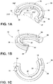
- FIGS. 1A-1C generally illustrate an embodiment of a spring isolator 10.
- Spring isolator 10 may include a ramp 18, a spring stop 20, a track/groove (i.e., spring track), 22, an inner wall 24, an outer wall 26, a locator pin 28, and/or a water drain 30.
- Spring isolator 10 may be configured (e.g., molded), of a flexible material (e.g., rubber).
- Spring isolator 10 may be configured to include a ramp 18 and/or a spring stop 20.
- Ramp 18 and/or spring stop 20 may be configured on opposite ends of spring isolator 10.
- a track/groove 22 may be configured to connect ramp 18 and/or spring stop 20.
- Track/groove 22 may include an inner wall 24 and/or an outer wall 26. Track/groove 22 may be configured to receive a spring (e.g., helical spring), such that an end of the spring may engage a spring stop 20 of a spring isolator 10.
- a spring e.g., helical spring
- One or more locator pins 28 may be integrated into spring isolator 10.
- One or more locator pin 28 may secure spring isolator 10 to a spring seat 32.
- locator pin is intended to encompass various formations that can be used as a locator.
- one or more water drains 30 may be included in spring isolator 10. Drains 30 may permit foreign and/or unwanted materials (e.g., water, debris) that may accumulate in spring isolator 10 to drain (e.g., exit).
- spring isolator 10 may be used in one or more locations in a vehicle suspension system.
- spring isolator 10 may be used in conjunction with a MacPherson strut system that may located in the front and/or rear of a vehicle.
- Spring isolator 10 may be configured at either end of the Macpherson strut system, or both.
- Spring isolator 10 may be configured for use in other vehicle suspension systems (e.g., double wishbone), that may include one or more coil springs 34 in either front and/or rear positions of a vehicle.
- spring isolator 10 may be engaged by coil spring 34.
- An end of coil spring 34 may engage spring stop 20 of spring isolator 10.
- Coil spring 34 may also engage a track/groove 22 that may extend radially from spring stop 20 to ramp 18.
- ramp 18 may be configured to begin approximately 184 degrees from spring stop 20. It should be understood that the position of ramp 18 relative to spring stop 20 is exemplary, and not limiting. Ramp 18 may be positioned at other angles relative to spring stop 20, such as, but not limited to, 145 degrees through 212 degrees. In embodiments, most of the vehicle suspension load transferred from coil spring 34 to spring isolator 10 may be concentrated at spring stop 20 and/or ramp 18. By including a reinforcing insert 14 within spring isolator 10, the vehicle suspension load previously concentrated at spring stop 20 and/or ramp 18 may be compensated (e.g., dispersed, distributed), throughout spring isolator 10 via track/groove 22.
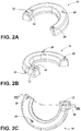
- FIGS. 2A-2C generally illustrate spring isolator 10.
- spring isolator 10 may be configured (e.g., molded), of a flexible material (e.g., rubber).
- cavity 12 may be included in spring isolator 10.
- cavity 12 may be configured in proximity to ramp 18.
- cavity 12 may be configured in proximity to spring stop 20.
- one or more cavities 12 may be configured about spring isolator 10.
- One or more cavities 12 may engage one or more raised portions 42 (see, e.g., FIG. 8 ), of spring seat 32.
- spring isolator 10 may include one or more locator pins 28 that may engage one or more locator pin holes 40 of spring seat 32.
- FIG. 3 generally illustrates reinforcing insert 14 associated with spring isolator 10.
- reinforcing insert may be disposed at least partially within spring isolator 10 (see, e.g., FIG. 5 ).
- Reinforcing insert 14 may include one or more flow holes 16, through which a moldable material (e.g., rubber, polymer), may flow.
- Reinforcing insert 14 may be constructed of materials that may strengthen spring isolator 10 (e.g., polymer, metal), and/or permit a load received from coil spring 34 to be compensated (e.g., distributed), via reinforcing insert 14.
- other suitably rigid and/or semi-rigid materials may be used to construct reinforcing insert 14.
- reinforcing insert 14 may be integrated (e.g., over-molded), by spring isolator 10 (see, e.g., FIGS. 5 and 8 ).
- Reinforcing insert 14 may include one or more flow holes (e.g., passages), 16.
- Flow holes 16 may permit a material (e.g., foam urethane elastomer), forming spring isolator 10 to pass through flow holes 16 and/or secure reinforcing insert within spring isolator 10.
- Reinforcing insert 14 may include ramp 18 that may be disposed at one end of reinforcing insert 14.
- Ramp 18 may engage track/groove 22, inner wall 24, and/or outer wall 26.
- Track/groove 22 may be configured with an incline (e.g., slope).
- Track/groove 22 may engage spring (e.g., coil, helical), 34.
- track/groove 22 of spring isolator 10 and/or reinforcing insert 14 may have a spring stop 20 at one end (i.e., first end), of track/groove 22 and a ramp 18 at the other end (e.g., second end), of track/groove 22.
- Spring stop 20 may include track/groove 22, inner wall 24, and/or outer wall 26.
- reinforcing insert 14 may include one or more locator pins 28. Locator pins 28 may be configured to engage spring seat 32 via one or more locator pin holes 40. In embodiments, locator pins 28 may be configured on a side of reinforcing insert 14 opposite of ramp 18 and/or spring stop 20.
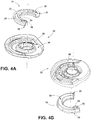
- FIGS. 4A-4B generally illustrate spring seat 32 associated with spring isolator 10.
- Spring seat 32 may include indentation 36 that may be configured to receive spring isolator 10.
- Spring seat 32 may include raised portion 42 that may be configured to engage cavity 12 of spring isolator 10.
- Cavity 12 may be included (i.e., integrated) in spring isolator 10.
- one or more cavities 12 and/or one or more locator pins 28 may engage and/or stabilize spring seat 10 within indentation 36.
- FIG. 5 generally illustrates spring seat 32 and coil spring 34 associated with spring isolator 10.
- Coil spring 34 may engage spring isolator 10 and/or spring seat 32. At least a portion of coil spring 34 may engage spring stop 20 of spring isolator 10. A portion of coil spring 34 extending from (e.g., adjacent to), the end of coil spring 34 may engage track/groove 22, inner wall 24, and/or outer wall 26 of spring isolator 10. At least a portion of coil spring 34 may engage ramp 18 of spring isolator 10. Ramp 18 may engage track/groove 22, inner wall 24, and/or outer wall 26.
- Spring seat 32 may be configured annularly around (e.g., about), shock passage 38. Shock passage 38 may be configured to receive and/or engage a shock absorber (e.g., damper).
- a shock absorber e.g., damper
- coil spring 34 may engage spring isolator 10. An end of the coil spring 34 may engage (e.g., contact), spring stop 20 of spring isolator 10. The coil spring 34 may be configured to engage ramp 18, track/groove 22, inner wall 24, and/or outer wall 26.
- a load may applied to coil spring 34 that may be transmitted (e.g., transferred), to spring isolator 10 and/or spring seat 32.
- the load may be applied in the form of a jounce and/or rebound load.
- a jounce load may be defined as the result of upward movement and/or compression of one or more suspension components, such as, but not limited to, coil spring 34.
- a rebound load may be defined as the downward movement and/or extension of one or more suspension components, such as, but not limited to, coil spring 34.
- ramp 18 and/or spring stop 20 may receive a large portion (e.g., 200 ⁇ 2000 N) of the load (e.g., jounce, rebound), transmitted by the coil spring to spring isolator 10.
- Spring isolator 10 may distribute and/or dissipate the load transmitted by the coil spring to spring seat 32.
- one or more locator pins 28 of spring isolator 10 may be configured to engage a spring seat 32 and/or prevent the movement (e.g., rotation), of spring isolator 10.
- FIGS. 6A-6B generally illustrate a spring seat 32 associated with a spring isolator (e.g., spring isolator 10 in FIGS. 1A-C , 2A-C , 4A-B ).
- spring isolator 10 may be associated with other suspension and/or body components of a vehicle and that the embodiments of spring seat 32 described herein are exemplary and not limiting.
- Spring seat 32 may include one or more locator pin holes 40 (i.e., receiving formations), that may engage one or more locator pins 28 of spring isolator 10.
- Locator pin holes 40 may be configured to engage locator pins 28 of different shapes and/or sizes (e.g., cylindrical, square), that may permit joining (e.g., assembly), of spring isolator 10 to spring seat 32 in one or more predetermined orientations.
- the configuration (e.g., placement), of locator pins 28 and/or locator pin holes 40 may permit the joining of spring isolator 10 and spring seat 32.
- spring isolator 10 may be configured to engage spring seat 32 annularly around (e.g., about), shock passage 38.
- FIGS. 7A-7B generally illustrate a spring seat 32 associated with a spring isolator (e.g., spring isolator 10 in FIGS. 1A-C , 2A-C , 4A-B ).
- Spring isolator 10 may be configured to engage an indentation 36 (e.g., as shown in FIG. 7B ), of spring seat 32.
- spring isolator 10 and/or spring seat 32 may be configured annularly about shock passage 38.
- One or more locator pins 28 of spring isolator 10 may engage one or more locator pin holes 40 of spring seat 32.
- Spring isolator 10 may include ramp 18, spring stop 20, track/groove 22, inner wall 24, outer wall 26, and/or water drain 30.
- Ramp 18 may be configured at one end of spring isolator 10. Ramp 18 may be configured to engage track/groove 22, inner wall 24, and/or outer wall 26 of spring isolator 10. In embodiments, at the opposite end of spring isolator 10, spring stop 20 may be configured to engage track/groove 22, inner wall 24, and/or outer wall 26 of spring isolator 10. In embodiments, one or more drains 30 may be configured to engage track/groove 22, inner wall 26, and/or outer wall 26 of spring isolator 10. In embodiments, drain 30 may be configured proximately to (e.g., near), ramp 18 and/or spring stop 20. In embodiments, drain 30 may be configured distally from (e.g., far), ramp 18 and/or spring stop 20. In embodiments, drain 30 may be configured to align with flow holes 16 and/or locator pin holes 40 of spring isolator 10 and spring seat 32, respectively.
- FIG. 8 generally illustrates spring seat 32 associated with spring isolator 10.
- Spring isolator 10 may be engage spring seat 32 via one or more locator pins 28.
- One or more locator pins 28 may be included with reinforcing insert 14 and/or spring isolator 10.
- locator pins 28 may engage spring seat 32 via one or more locator pin holes 40.
- locator pins 28 may include fastening elements (e.g., threads, rivets), that may secure spring isolator 10 to spring seat 40.
- locator pins 28 may be processed (e.g., welded, compressed, flattened), after insertion in locator pin holes 40.
- spring isolator 10 may include one or more cavities 12.
- Cavity 12 may be configured on spring isolator 10 such that cavity 12 may engage spring seat 32 via a raised portion 42 of spring seat 32.
- locator pins 28 and/or raised portion 42 may engage (e.g., interlock), with spring isolator 10. Locator pins 28 and/or raised portion 42 may permit spring isolator 10 to remain in indentation 36 of spring seat 32. In embodiments, locator pins 28 and/or raised portion 42 may permit an operator to position spring isolator 10 in indentation 36 of spring seat 10.
- joinder references do not necessarily imply that two elements are directly connected/coupled and in fixed relation to each other.
- the terms “electrically connected” and “in communication” are meant to be construed broadly to encompass both wired and wireless connections and communications. It is intended that all matter contained in the above description or shown in the accompanying drawings shall be interpreted as illustrative only and not limiting. Changes in detail or structure may be made without departing from the invention as defined in the appended claims.
Landscapes
- Engineering & Computer Science (AREA)
- Mechanical Engineering (AREA)
- General Engineering & Computer Science (AREA)
- Springs (AREA)
Claims (15)
- Federisolatoranordnung, wobei die Anordnung umfasst:einen Verstärkungseinsatz (14),einen Federisolator (10) mit einer Rampe (18) und einem Federanschlag (20), wobei der Federisolator aus einem flexiblen Material ausgebildet ist, das dazu ausgebildet ist, einen Teil einer Feder (34) aufzunehmen, wobei der Federisolator (10) eine Federspur (22), eine Innenwand (24) und eine Außenwand (26) aufweist, wobei der Verstärkungseinsatz (14) in den Federisolator (10) integriert ist und die Rampe (18) und der Federanschlag (20) an gegenüberliegenden Enden des Federisolators (10) ausgebildet sind, wobei der Federisolator (10) mindestens einen Abfluss (30) umfasst, wobei der Abfluss (30) zum Entfernen von Wasser und/oder Schmutz von der Federspur (22) ausgebildet ist.
- Federisolatoranordnung gemäß Anspruch 1, wobei der Verstärkungseinsatz (14) aus einem Metall oder Polymer besteht.
- Federisolatoranordnung gemäß Anspruch 1, wobei der Verstärkungseinsatz (14) ferner einen Durchgang (16) aufweist, durch den ein Abschnitt der Außenschicht mit dem Verstärkungseinsatz (14) in Eingriff kommt.
- Federisolatoranordnung gemäß Anspruch 1, wobei der Federisolator (10) einen Positionierstift (28) aufweist, der aus dem Federisolator (10) herausragt und dazu ausgebildet ist, den Federisolator (10) an einem Federsitz (32) zu befestigen.
- Federisolatoranordnung gemäß Anspruch 1, wobei die Federspur (22) dazu ausgebildet ist, die Rampe (18) und den Federanschlag (20) zu verbinden.
- Federisolatoranordnung gemäß Anspruch 5, wobei die Federspur (22) zur Aufnahme einer Feder (34) ausgebildet ist.
- Federisolatoranordnung gemäß Anspruch 6, wobei die Innenwand (24) und die Außenwand (26) an einem Teil der Rampe (18) anliegen.
- Federisolatoranordnung gemäß Anspruch 1, wobei der Federanschlag (20) dazu ausgebildet ist, mit einem Ende einer Schraubenfeder (34) in Eingriff zu kommen und/oder die Federspur (22) dazu ausgebildet ist, mit einer Schraubenfeder (34) in Eingriff zu kommen.
- Federisolatoranordnung gemäß Anspruch 1, wobei der Abfluss (30) nahe der Rampe (18) und/oder des Federanschlags (20) ausgebildet ist.
- Federisolatoranordnung gemäß Anspruch 1, wobei der Federisolator (10) ferner einen Hohlraum (12) umfasst, wobei der Hohlraum (12) dazu ausgebildet ist, mit einem erhöhten Abschnitt (42) eines Federsitzes (32) in Eingriff zu kommen.
- Federisolatoranordnung, wobei die Anordnung umfasst:einen Verstärkungseinsatz (14), wobei der Verstärkungseinsatz (14) eine Rampe (18) und einen Schraubenfederanschlag (20) aufweist; undeine radiale Außenschicht, die aus einem formbaren flexiblen Material besteht, wobei die radiale Außenschicht den Verstärkungseinsatz (14) umgibt,wobei die Rampe (18) sich an einem ersten Ende befindet, der Schraubenfederanschlag (20) sich an einem zweiten Ende befindet und eine Dicke des Verstärkungseinsatzes (14) in einer vertikalen Richtung entlang einer gekrümmten Länge des Verstärkungseinsatzes (14) variiert und die Dicke der Rampe (18) größer als die Dicke des Verstärkungseinsatzes (14) angrenzend an die Rampe (18) ist, wobei die Federisolatoranordnung mindestens einen Abfluss (30) umfasst, damit Fremdstoffe und/oder unerwünschte Materialien, die sich in der Federisolatoranordnung ansammeln könnten, ablaufen können.
- Federisolatoranordnung gemäß Anspruch 11, wobei der Verstärkungseinsatz (14) eine Vielzahl von Durchgängen (16) aufweist, die dazu ausgelegt sind, mit einer oder mehreren der radialen Außenschichten und einem Positionierstift (28) in Eingriff zu kommen, um selektiv mit einem Schraubenfedersitz (32) in Eingriff zu kommen.
- Federisolatoranordnung gemäß Anspruch 11, wobei sich die Rampe (18) zwischen 145 Grad und 212 Grad radial vom Federanschlag (20) befindet.
- Federisolatoranordnung gemäß Anspruch 11, wobei die radiale Außenschicht eine Schraubenfederspur (22) aufweist, die zwischen einer Innenwand (24) und einer Außenwand (26) angeordnet ist, um selektiv mit einer Schraubenfeder (34) in Eingriff zu kommen.
- Federisolatoranordnung gemäß Anspruch 11, ferner umfassend mindestens einen Positionierstift (28), einen erhöhten Abschnitt (42) und/oder einen Hohlraum (12) zum selektiven Eingriff mit einen Abschnitt eines Schraubenfedersitzes (32).
Applications Claiming Priority (3)
| Application Number | Priority Date | Filing Date | Title |
|---|---|---|---|
| US201662407174P | 2016-10-12 | 2016-10-12 | |
| US15/729,902 US10495170B2 (en) | 2016-10-12 | 2017-10-11 | Load compensating spring isolator |
| PCT/US2017/056328 WO2018071661A1 (en) | 2016-10-12 | 2017-10-12 | Load compensating spring isolator |
Publications (2)
| Publication Number | Publication Date |
|---|---|
| EP3526488A1 EP3526488A1 (de) | 2019-08-21 |
| EP3526488B1 true EP3526488B1 (de) | 2021-12-01 |
Family
ID=61829764
Family Applications (1)
| Application Number | Title | Priority Date | Filing Date |
|---|---|---|---|
| EP17793759.6A Active EP3526488B1 (de) | 2016-10-12 | 2017-10-12 | Lastkompensierender federisolator |
Country Status (4)
| Country | Link |
|---|---|
| US (1) | US10495170B2 (de) |
| EP (1) | EP3526488B1 (de) |
| CN (1) | CN109844353A (de) |
| WO (1) | WO2018071661A1 (de) |
Families Citing this family (6)
| Publication number | Priority date | Publication date | Assignee | Title |
|---|---|---|---|---|
| KR102039936B1 (ko) * | 2019-04-19 | 2019-11-04 | 대원강업주식회사 | 자동차 현가장치 코일스프링용 본디드 패드 및 그 제조 방법 |
| JP7527921B2 (ja) * | 2020-10-01 | 2024-08-05 | 株式会社Subaru | サスペンション装置 |
| WO2023214422A1 (en) | 2022-05-05 | 2023-11-09 | Rut3 Engineering Pvt. Ltd. | A wheel suspension system |
| CN120379849A (zh) * | 2022-12-20 | 2025-07-25 | 巴斯夫欧洲公司 | 混合式螺旋弹簧隔离器 |
| US12479251B2 (en) | 2024-02-06 | 2025-11-25 | Fca Us Llc | Rear lower isolator |
| WO2026046779A1 (en) | 2024-08-29 | 2026-03-05 | Basf Polyurethanes Gmbh | Coil spring isolator and corresponding coil spring assembly |
Citations (3)
| Publication number | Priority date | Publication date | Assignee | Title |
|---|---|---|---|---|
| GB2241765A (en) * | 1990-03-09 | 1991-09-11 | Fichtel & Sachs Ag | Suspension strut |
| US20140265081A1 (en) * | 2013-03-12 | 2014-09-18 | Showa Corporation | Elastic sheet and suspension apparatus |
| US20160107497A1 (en) * | 2014-10-21 | 2016-04-21 | Ford Global Technologies, Llc | Spring isolators and suspension systems incorporating same |
Family Cites Families (11)
| Publication number | Priority date | Publication date | Assignee | Title |
|---|---|---|---|---|
| US6149171A (en) * | 1999-03-31 | 2000-11-21 | Daimlerchrysler Corporation | Spring isolator for a motor vehicle suspension |
| US20030222386A1 (en) | 2001-11-27 | 2003-12-04 | Markus Duerre | Combined spring seat isolator and mass damper |
| JP4055845B2 (ja) * | 2002-05-08 | 2008-03-05 | 株式会社ショーワ | 油圧緩衝器のダストカバー受け構造 |
| DE102005032449A1 (de) | 2005-07-12 | 2007-01-18 | Zf Friedrichshafen Ag | Federteller-Auflage |
| CN100497989C (zh) * | 2006-02-21 | 2009-06-10 | 东海橡胶工业株式会社 | 机动车悬架的弹簧座 |
| JP5151770B2 (ja) * | 2007-11-26 | 2013-02-27 | 日産自動車株式会社 | ロアスプリングシートの取り付け構造及びロアスプリングシート |
| JP5293340B2 (ja) * | 2009-03-30 | 2013-09-18 | スズキ株式会社 | スプリングシート及びスプリングシートの取り付け構造 |
| DE102010028290B4 (de) | 2010-04-28 | 2019-01-31 | Zf Friedrichshafen Ag | Federteller |
| JP5961128B2 (ja) * | 2013-03-21 | 2016-08-02 | Kyb株式会社 | スプリングラバーシート及びストラット型サスペンション |
| KR102300647B1 (ko) * | 2014-10-30 | 2021-09-10 | 현대모비스 주식회사 | 멀티링크 서스펜션 |
| CN205533992U (zh) * | 2016-01-27 | 2016-08-31 | 安徽中鼎密封件股份有限公司 | 一种汽车减震器用弹簧缓冲橡胶垫 |
-
2017
- 2017-10-11 US US15/729,902 patent/US10495170B2/en active Active
- 2017-10-12 EP EP17793759.6A patent/EP3526488B1/de active Active
- 2017-10-12 WO PCT/US2017/056328 patent/WO2018071661A1/en not_active Ceased
- 2017-10-12 CN CN201780062587.0A patent/CN109844353A/zh active Pending
Patent Citations (3)
| Publication number | Priority date | Publication date | Assignee | Title |
|---|---|---|---|---|
| GB2241765A (en) * | 1990-03-09 | 1991-09-11 | Fichtel & Sachs Ag | Suspension strut |
| US20140265081A1 (en) * | 2013-03-12 | 2014-09-18 | Showa Corporation | Elastic sheet and suspension apparatus |
| US20160107497A1 (en) * | 2014-10-21 | 2016-04-21 | Ford Global Technologies, Llc | Spring isolators and suspension systems incorporating same |
Also Published As
| Publication number | Publication date |
|---|---|
| EP3526488A1 (de) | 2019-08-21 |
| US10495170B2 (en) | 2019-12-03 |
| CN109844353A (zh) | 2019-06-04 |
| WO2018071661A1 (en) | 2018-04-19 |
| US20180100556A1 (en) | 2018-04-12 |
Similar Documents
| Publication | Publication Date | Title |
|---|---|---|
| EP3526488B1 (de) | Lastkompensierender federisolator | |
| US20180111436A1 (en) | Proportional radial loading spring isolator | |
| US7389977B1 (en) | Body mount assembly with combined shear and compression style components | |
| US10442262B2 (en) | Hybrid arm and method of manufacturing same | |
| CN105377594B (zh) | 车辆悬架及其板簧 | |
| CN104080626B (zh) | 包括轻量板簧组件的车辆悬架 | |
| US9950583B2 (en) | Spring seat | |
| US20200062062A1 (en) | Top mount assembly and manufacturing method therefor | |
| US20140300074A1 (en) | One-Shell Spring Suspension Arm | |
| CN107580560B (zh) | 车辆悬架的减震器组件和悬架系统 | |
| CN105523089A (zh) | 将弹簧腿连接在车辆车身上的支承结构部件及弹簧腿套管 | |
| CN103534506A (zh) | 垫圈组件 | |
| CN105387074A (zh) | 支架轴承单元,配备支架轴承单元的机动车辆和制造方法 | |
| US20030222386A1 (en) | Combined spring seat isolator and mass damper | |
| EP3290241A1 (de) | Hybrider unterarm | |
| KR101479594B1 (ko) | 현가장치의 인슐레이터 | |
| US12320402B2 (en) | Mounting bushing | |
| US7959172B2 (en) | Push-in-bung assembly and suspension system using same | |
| CN106627020A (zh) | 机动车辆的弹簧装置 | |
| KR20170099712A (ko) | 트레일링암 부시 | |
| KR20100067312A (ko) | 자동차 로어암 및 쇽업쇼버 브라켓 어셈블리 장치 | |
| KR102452684B1 (ko) | 쇽업소버의 인슐레이터 부시, 인슐레이터 조립체 및 그 제조방법 | |
| KR101582854B1 (ko) | 차량용 전륜 에어스프링 | |
| KR101724457B1 (ko) | 차량의 리어 쇽 업소버 장착구조 | |
| KR101382966B1 (ko) | 리어 액슬 모듈 제조 공법 및 이를 이용한 커플드 터뷸라 빔 액슬 현가장치 |
Legal Events
| Date | Code | Title | Description |
|---|---|---|---|
| STAA | Information on the status of an ep patent application or granted ep patent |
Free format text: STATUS: UNKNOWN |
|
| STAA | Information on the status of an ep patent application or granted ep patent |
Free format text: STATUS: THE INTERNATIONAL PUBLICATION HAS BEEN MADE |
|
| PUAI | Public reference made under article 153(3) epc to a published international application that has entered the european phase |
Free format text: ORIGINAL CODE: 0009012 |
|
| STAA | Information on the status of an ep patent application or granted ep patent |
Free format text: STATUS: REQUEST FOR EXAMINATION WAS MADE |
|
| 17P | Request for examination filed |
Effective date: 20190503 |
|
| AK | Designated contracting states |
Kind code of ref document: A1 Designated state(s): AL AT BE BG CH CY CZ DE DK EE ES FI FR GB GR HR HU IE IS IT LI LT LU LV MC MK MT NL NO PL PT RO RS SE SI SK SM TR |
|
| AX | Request for extension of the european patent |
Extension state: BA ME |
|
| RIN1 | Information on inventor provided before grant (corrected) |
Inventor name: LOVE, MICKEY, L. Inventor name: DUTTON, LEE, HAYDEN Inventor name: CUMMINGS, NEIL, STEWART |
|
| RIN1 | Information on inventor provided before grant (corrected) |
Inventor name: DUTTON, LEE, HAYDEN Inventor name: LOVE, MICKEY, L. Inventor name: CUMMINGS, NEIL, STEWART |
|
| DAV | Request for validation of the european patent (deleted) | ||
| DAX | Request for extension of the european patent (deleted) | ||
| STAA | Information on the status of an ep patent application or granted ep patent |
Free format text: STATUS: EXAMINATION IS IN PROGRESS |
|
| 17Q | First examination report despatched |
Effective date: 20200316 |
|
| GRAP | Despatch of communication of intention to grant a patent |
Free format text: ORIGINAL CODE: EPIDOSNIGR1 |
|
| STAA | Information on the status of an ep patent application or granted ep patent |
Free format text: STATUS: GRANT OF PATENT IS INTENDED |
|
| INTG | Intention to grant announced |
Effective date: 20210518 |
|
| GRAS | Grant fee paid |
Free format text: ORIGINAL CODE: EPIDOSNIGR3 |
|
| RIN1 | Information on inventor provided before grant (corrected) |
Inventor name: DUTTON, LEE HAYDEN Inventor name: CUMMINGS, NEIL, STEWART Inventor name: LOVE, MICKEY L. |
|
| GRAA | (expected) grant |
Free format text: ORIGINAL CODE: 0009210 |
|
| STAA | Information on the status of an ep patent application or granted ep patent |
Free format text: STATUS: THE PATENT HAS BEEN GRANTED |
|
| AK | Designated contracting states |
Kind code of ref document: B1 Designated state(s): AL AT BE BG CH CY CZ DE DK EE ES FI FR GB GR HR HU IE IS IT LI LT LU LV MC MK MT NL NO PL PT RO RS SE SI SK SM TR |
|
| REG | Reference to a national code |
Ref country code: GB Ref legal event code: FG4D |
|
| REG | Reference to a national code |
Ref country code: AT Ref legal event code: REF Ref document number: 1452044 Country of ref document: AT Kind code of ref document: T Effective date: 20211215 Ref country code: CH Ref legal event code: EP |
|
| REG | Reference to a national code |
Ref country code: IE Ref legal event code: FG4D |
|
| REG | Reference to a national code |
Ref country code: DE Ref legal event code: R096 Ref document number: 602017050297 Country of ref document: DE |
|
| REG | Reference to a national code |
Ref country code: LT Ref legal event code: MG9D |
|
| REG | Reference to a national code |
Ref country code: NL Ref legal event code: MP Effective date: 20211201 |
|
| REG | Reference to a national code |
Ref country code: AT Ref legal event code: MK05 Ref document number: 1452044 Country of ref document: AT Kind code of ref document: T Effective date: 20211201 |
|
| PG25 | Lapsed in a contracting state [announced via postgrant information from national office to epo] |
Ref country code: RS Free format text: LAPSE BECAUSE OF FAILURE TO SUBMIT A TRANSLATION OF THE DESCRIPTION OR TO PAY THE FEE WITHIN THE PRESCRIBED TIME-LIMIT Effective date: 20211201 Ref country code: LT Free format text: LAPSE BECAUSE OF FAILURE TO SUBMIT A TRANSLATION OF THE DESCRIPTION OR TO PAY THE FEE WITHIN THE PRESCRIBED TIME-LIMIT Effective date: 20211201 Ref country code: FI Free format text: LAPSE BECAUSE OF FAILURE TO SUBMIT A TRANSLATION OF THE DESCRIPTION OR TO PAY THE FEE WITHIN THE PRESCRIBED TIME-LIMIT Effective date: 20211201 Ref country code: BG Free format text: LAPSE BECAUSE OF FAILURE TO SUBMIT A TRANSLATION OF THE DESCRIPTION OR TO PAY THE FEE WITHIN THE PRESCRIBED TIME-LIMIT Effective date: 20220301 Ref country code: AT Free format text: LAPSE BECAUSE OF FAILURE TO SUBMIT A TRANSLATION OF THE DESCRIPTION OR TO PAY THE FEE WITHIN THE PRESCRIBED TIME-LIMIT Effective date: 20211201 |
|
| PG25 | Lapsed in a contracting state [announced via postgrant information from national office to epo] |
Ref country code: SE Free format text: LAPSE BECAUSE OF FAILURE TO SUBMIT A TRANSLATION OF THE DESCRIPTION OR TO PAY THE FEE WITHIN THE PRESCRIBED TIME-LIMIT Effective date: 20211201 Ref country code: PL Free format text: LAPSE BECAUSE OF FAILURE TO SUBMIT A TRANSLATION OF THE DESCRIPTION OR TO PAY THE FEE WITHIN THE PRESCRIBED TIME-LIMIT Effective date: 20211201 Ref country code: NO Free format text: LAPSE BECAUSE OF FAILURE TO SUBMIT A TRANSLATION OF THE DESCRIPTION OR TO PAY THE FEE WITHIN THE PRESCRIBED TIME-LIMIT Effective date: 20220301 Ref country code: LV Free format text: LAPSE BECAUSE OF FAILURE TO SUBMIT A TRANSLATION OF THE DESCRIPTION OR TO PAY THE FEE WITHIN THE PRESCRIBED TIME-LIMIT Effective date: 20211201 Ref country code: HR Free format text: LAPSE BECAUSE OF FAILURE TO SUBMIT A TRANSLATION OF THE DESCRIPTION OR TO PAY THE FEE WITHIN THE PRESCRIBED TIME-LIMIT Effective date: 20211201 Ref country code: GR Free format text: LAPSE BECAUSE OF FAILURE TO SUBMIT A TRANSLATION OF THE DESCRIPTION OR TO PAY THE FEE WITHIN THE PRESCRIBED TIME-LIMIT Effective date: 20220302 Ref country code: ES Free format text: LAPSE BECAUSE OF FAILURE TO SUBMIT A TRANSLATION OF THE DESCRIPTION OR TO PAY THE FEE WITHIN THE PRESCRIBED TIME-LIMIT Effective date: 20211201 |
|
| PG25 | Lapsed in a contracting state [announced via postgrant information from national office to epo] |
Ref country code: NL Free format text: LAPSE BECAUSE OF FAILURE TO SUBMIT A TRANSLATION OF THE DESCRIPTION OR TO PAY THE FEE WITHIN THE PRESCRIBED TIME-LIMIT Effective date: 20211201 |
|
| PG25 | Lapsed in a contracting state [announced via postgrant information from national office to epo] |
Ref country code: SM Free format text: LAPSE BECAUSE OF FAILURE TO SUBMIT A TRANSLATION OF THE DESCRIPTION OR TO PAY THE FEE WITHIN THE PRESCRIBED TIME-LIMIT Effective date: 20211201 Ref country code: SK Free format text: LAPSE BECAUSE OF FAILURE TO SUBMIT A TRANSLATION OF THE DESCRIPTION OR TO PAY THE FEE WITHIN THE PRESCRIBED TIME-LIMIT Effective date: 20211201 Ref country code: RO Free format text: LAPSE BECAUSE OF FAILURE TO SUBMIT A TRANSLATION OF THE DESCRIPTION OR TO PAY THE FEE WITHIN THE PRESCRIBED TIME-LIMIT Effective date: 20211201 Ref country code: PT Free format text: LAPSE BECAUSE OF FAILURE TO SUBMIT A TRANSLATION OF THE DESCRIPTION OR TO PAY THE FEE WITHIN THE PRESCRIBED TIME-LIMIT Effective date: 20220401 Ref country code: EE Free format text: LAPSE BECAUSE OF FAILURE TO SUBMIT A TRANSLATION OF THE DESCRIPTION OR TO PAY THE FEE WITHIN THE PRESCRIBED TIME-LIMIT Effective date: 20211201 Ref country code: CZ Free format text: LAPSE BECAUSE OF FAILURE TO SUBMIT A TRANSLATION OF THE DESCRIPTION OR TO PAY THE FEE WITHIN THE PRESCRIBED TIME-LIMIT Effective date: 20211201 |
|
| REG | Reference to a national code |
Ref country code: DE Ref legal event code: R097 Ref document number: 602017050297 Country of ref document: DE |
|
| PG25 | Lapsed in a contracting state [announced via postgrant information from national office to epo] |
Ref country code: IS Free format text: LAPSE BECAUSE OF FAILURE TO SUBMIT A TRANSLATION OF THE DESCRIPTION OR TO PAY THE FEE WITHIN THE PRESCRIBED TIME-LIMIT Effective date: 20220401 |
|
| PLBE | No opposition filed within time limit |
Free format text: ORIGINAL CODE: 0009261 |
|
| STAA | Information on the status of an ep patent application or granted ep patent |
Free format text: STATUS: NO OPPOSITION FILED WITHIN TIME LIMIT |
|
| PG25 | Lapsed in a contracting state [announced via postgrant information from national office to epo] |
Ref country code: DK Free format text: LAPSE BECAUSE OF FAILURE TO SUBMIT A TRANSLATION OF THE DESCRIPTION OR TO PAY THE FEE WITHIN THE PRESCRIBED TIME-LIMIT Effective date: 20211201 Ref country code: AL Free format text: LAPSE BECAUSE OF FAILURE TO SUBMIT A TRANSLATION OF THE DESCRIPTION OR TO PAY THE FEE WITHIN THE PRESCRIBED TIME-LIMIT Effective date: 20211201 |
|
| 26N | No opposition filed |
Effective date: 20220902 |
|
| PG25 | Lapsed in a contracting state [announced via postgrant information from national office to epo] |
Ref country code: SI Free format text: LAPSE BECAUSE OF FAILURE TO SUBMIT A TRANSLATION OF THE DESCRIPTION OR TO PAY THE FEE WITHIN THE PRESCRIBED TIME-LIMIT Effective date: 20211201 |
|
| PG25 | Lapsed in a contracting state [announced via postgrant information from national office to epo] |
Ref country code: MC Free format text: LAPSE BECAUSE OF FAILURE TO SUBMIT A TRANSLATION OF THE DESCRIPTION OR TO PAY THE FEE WITHIN THE PRESCRIBED TIME-LIMIT Effective date: 20211201 Ref country code: IT Free format text: LAPSE BECAUSE OF FAILURE TO SUBMIT A TRANSLATION OF THE DESCRIPTION OR TO PAY THE FEE WITHIN THE PRESCRIBED TIME-LIMIT Effective date: 20211201 |
|
| REG | Reference to a national code |
Ref country code: CH Ref legal event code: PL |
|
| REG | Reference to a national code |
Ref country code: BE Ref legal event code: MM Effective date: 20221031 |
|
| PG25 | Lapsed in a contracting state [announced via postgrant information from national office to epo] |
Ref country code: LU Free format text: LAPSE BECAUSE OF NON-PAYMENT OF DUE FEES Effective date: 20221012 |
|
| PG25 | Lapsed in a contracting state [announced via postgrant information from national office to epo] |
Ref country code: LI Free format text: LAPSE BECAUSE OF NON-PAYMENT OF DUE FEES Effective date: 20221031 Ref country code: CH Free format text: LAPSE BECAUSE OF NON-PAYMENT OF DUE FEES Effective date: 20221031 |
|
| PG25 | Lapsed in a contracting state [announced via postgrant information from national office to epo] |
Ref country code: BE Free format text: LAPSE BECAUSE OF NON-PAYMENT OF DUE FEES Effective date: 20221031 |
|
| PG25 | Lapsed in a contracting state [announced via postgrant information from national office to epo] |
Ref country code: IE Free format text: LAPSE BECAUSE OF NON-PAYMENT OF DUE FEES Effective date: 20221012 |
|
| PG25 | Lapsed in a contracting state [announced via postgrant information from national office to epo] |
Ref country code: HU Free format text: LAPSE BECAUSE OF FAILURE TO SUBMIT A TRANSLATION OF THE DESCRIPTION OR TO PAY THE FEE WITHIN THE PRESCRIBED TIME-LIMIT; INVALID AB INITIO Effective date: 20171012 |
|
| PG25 | Lapsed in a contracting state [announced via postgrant information from national office to epo] |
Ref country code: CY Free format text: LAPSE BECAUSE OF FAILURE TO SUBMIT A TRANSLATION OF THE DESCRIPTION OR TO PAY THE FEE WITHIN THE PRESCRIBED TIME-LIMIT Effective date: 20211201 |
|
| PG25 | Lapsed in a contracting state [announced via postgrant information from national office to epo] |
Ref country code: MK Free format text: LAPSE BECAUSE OF FAILURE TO SUBMIT A TRANSLATION OF THE DESCRIPTION OR TO PAY THE FEE WITHIN THE PRESCRIBED TIME-LIMIT Effective date: 20211201 |
|
| PG25 | Lapsed in a contracting state [announced via postgrant information from national office to epo] |
Ref country code: MT Free format text: LAPSE BECAUSE OF FAILURE TO SUBMIT A TRANSLATION OF THE DESCRIPTION OR TO PAY THE FEE WITHIN THE PRESCRIBED TIME-LIMIT Effective date: 20211201 |
|
| PGFP | Annual fee paid to national office [announced via postgrant information from national office to epo] |
Ref country code: DE Payment date: 20241031 Year of fee payment: 8 |
|
| PGFP | Annual fee paid to national office [announced via postgrant information from national office to epo] |
Ref country code: GB Payment date: 20241030 Year of fee payment: 8 |
|
| PGFP | Annual fee paid to national office [announced via postgrant information from national office to epo] |
Ref country code: FR Payment date: 20241030 Year of fee payment: 8 |
|
| PG25 | Lapsed in a contracting state [announced via postgrant information from national office to epo] |
Ref country code: TR Free format text: LAPSE BECAUSE OF FAILURE TO SUBMIT A TRANSLATION OF THE DESCRIPTION OR TO PAY THE FEE WITHIN THE PRESCRIBED TIME-LIMIT Effective date: 20211201 |