EP3524868A1 - Vorrichtung zum abdichten einer ausnehmung in einem objekt - Google Patents
Vorrichtung zum abdichten einer ausnehmung in einem objekt Download PDFInfo
- Publication number
- EP3524868A1 EP3524868A1 EP19155885.7A EP19155885A EP3524868A1 EP 3524868 A1 EP3524868 A1 EP 3524868A1 EP 19155885 A EP19155885 A EP 19155885A EP 3524868 A1 EP3524868 A1 EP 3524868A1
- Authority
- EP
- European Patent Office
- Prior art keywords
- deformation body
- recess
- contact surface
- deformation
- clamping
- Prior art date
- Legal status (The legal status is an assumption and is not a legal conclusion. Google has not performed a legal analysis and makes no representation as to the accuracy of the status listed.)
- Granted
Links
Images



Classifications
-
- F—MECHANICAL ENGINEERING; LIGHTING; HEATING; WEAPONS; BLASTING
- F16—ENGINEERING ELEMENTS AND UNITS; GENERAL MEASURES FOR PRODUCING AND MAINTAINING EFFECTIVE FUNCTIONING OF MACHINES OR INSTALLATIONS; THERMAL INSULATION IN GENERAL
- F16L—PIPES; JOINTS OR FITTINGS FOR PIPES; SUPPORTS FOR PIPES, CABLES OR PROTECTIVE TUBING; MEANS FOR THERMAL INSULATION IN GENERAL
- F16L55/00—Devices or appurtenances for use in, or in connection with, pipes or pipe systems
- F16L55/10—Means for stopping flow in pipes or hoses
- F16L55/12—Means for stopping flow in pipes or hoses by introducing into the pipe a member expandable in situ
- F16L55/128—Means for stopping flow in pipes or hoses by introducing into the pipe a member expandable in situ introduced axially into the pipe or hose
- F16L55/132—Means for stopping flow in pipes or hoses by introducing into the pipe a member expandable in situ introduced axially into the pipe or hose the closure device being a plug fixed by radially deforming the packing
-
- F—MECHANICAL ENGINEERING; LIGHTING; HEATING; WEAPONS; BLASTING
- F16—ENGINEERING ELEMENTS AND UNITS; GENERAL MEASURES FOR PRODUCING AND MAINTAINING EFFECTIVE FUNCTIONING OF MACHINES OR INSTALLATIONS; THERMAL INSULATION IN GENERAL
- F16J—PISTONS; CYLINDERS; SEALINGS
- F16J13/00—Covers or similar closure members for pressure vessels in general
- F16J13/02—Detachable closure members; Means for tightening closures
- F16J13/14—Detachable closure members; Means for tightening closures attached exclusively by spring action or elastic action
-
- F—MECHANICAL ENGINEERING; LIGHTING; HEATING; WEAPONS; BLASTING
- F16—ENGINEERING ELEMENTS AND UNITS; GENERAL MEASURES FOR PRODUCING AND MAINTAINING EFFECTIVE FUNCTIONING OF MACHINES OR INSTALLATIONS; THERMAL INSULATION IN GENERAL
- F16J—PISTONS; CYLINDERS; SEALINGS
- F16J15/00—Sealings
- F16J15/02—Sealings between relatively-stationary surfaces
- F16J15/021—Sealings between relatively-stationary surfaces with elastic packing
- F16J15/028—Sealings between relatively-stationary surfaces with elastic packing the packing being mechanically expanded against the sealing surface
-
- B—PERFORMING OPERATIONS; TRANSPORTING
- B65—CONVEYING; PACKING; STORING; HANDLING THIN OR FILAMENTARY MATERIAL
- B65D—CONTAINERS FOR STORAGE OR TRANSPORT OF ARTICLES OR MATERIALS, e.g. BAGS, BARRELS, BOTTLES, BOXES, CANS, CARTONS, CRATES, DRUMS, JARS, TANKS, HOPPERS, FORWARDING CONTAINERS; ACCESSORIES, CLOSURES, OR FITTINGS THEREFOR; PACKAGING ELEMENTS; PACKAGES
- B65D39/00—Closures arranged within necks or pouring openings or in discharge apertures, e.g. stoppers
- B65D39/12—Closures arranged within necks or pouring openings or in discharge apertures, e.g. stoppers expansible, e.g. inflatable
Definitions
- the invention relates to a device for sealing a recess in an object according to the preamble of patent claim 1 and an assembly according to the preamble of patent claim 12.
- the object can be, for example, a plate or a housing segment.
- liquid-tight and / or gas-tight sealing may be desired, for example to protect material or electronic components from moisture.
- a borehole cover in which a deformation body to be inserted into the recess is deformable by means of a disk pair such that the outer casing of the deformation body is pressed against the inner contour of the borehole so that a sealing effect is achieved.
- the object underlying the invention is thus to simplify the assembly process of sealing devices for recesses.
- a device of the aforementioned type wherein a pressure plate of the device can be pressed by means of a clamping body of a clamping device against a deformation body.
- the pressure disk is designed such that the pressure disk can be inserted between the deformation body and the tension body during the assembly process of the apparatus.
- the invention makes use of the finding that a one-hand assembly is possible if the deformation body together with the clamping device during the assembly process of the device positionally stable in the recess can be arranged and a subsequent insertion of the pressure plate between the deformation body and the clamping body of the clamping device is possible. Due to the fact that the thrust washer can be inserted between the deformation body and the clamping body, the deformation body can be secured from falling out before the thrust washer is inserted by means of the clamping body of the tensioning device. An additional retention of the deformation body before or during the insertion of the pressure plate is no longer necessary. Accordingly, the device allows a one-hand assembly, so that the assembly process is much easier.
- the device for sealing the recess may also be referred to as a pinch seal. Due to the change in shape of the deformation body large tolerance fluctuations due to irregular or unclean manufacturing can be compensated easily.
- the thrust washer has a slot-shaped recess, which preferably extends from an outer edge of the thrust washer to a central region of the thrust washer.
- the pressure plate can be pushed between the deformation body and the clamping body are, wherein a part of the clamping device is arranged during insertion within the slot-shaped recess of the pressure plate. After the pressure disk has been inserted between the deformation body and the clamping body, a part of the tensioning device extends through the central region of the slot-shaped recess.
- a device according to the invention is preferred in which the clamping device has an elongated element with an external thread, wherein the clamping body has an internal thread corresponding to the external thread.
- the elongated element may be, for example, a screw or a threaded rod.
- the elongate member may be a component of a screw or a threaded rod.
- the screw can be a round-head screw.
- the clamping body may be formed for example as a mother. A washer can be arranged between the thrust washer and the clamping body.
- the device according to the invention has a stop disk, which has a contact surface for the deformation body.
- the contact surface of the stop disk can be pressed against the deformation body by means of the tensioning device.
- the thrust washer and the stop disc are arranged in the assembled state of the device on opposite sides of the deformation body.
- the deformation body, the pressure disk and / or the stop disk preferably have a substantially circular basic shape.
- the pressure disk and / or the stop disk preferably projects beyond the deformation body in the mounted state of the device.
- the stop disk has a through hole through which the elongate element of the clamping device extends.
- the through hole is preferably arranged in a central region of the stop disk and / or has a circular cross section.
- the central region of the slot-shaped recess in the pressure plate in the assembled state of Device brought into coincidence with the through hole of the stop disk.
- a device in which on the side facing away from the deformation body of the stop disk, a through-hole projecting end portion of the elongated member is arranged.
- the end portion of the elongate member is preferably formed as a screw head.
- the end portion has a substantially annular contact surface, which in the mounted state of the device is in contact with the side of the stop disk opposite the deformation body.
- the clamping device has an anti-twist device.
- the anti-rotation ensures that occurring during assembly torque load on the clamping device does not lead to a rotation of the clamping device.
- the elongate element is designed as a screw and the clamping body as a nut, can be effectively prevented by the rotation of a turning of the screw when screwing the nut.
- the anti-rotation is implemented by a positive connection.
- the elongate element has a securing portion, which can be coupled against rotation with the deformation body and / or the stop disk.
- the elongated element in the region of the securing portion has a hexagonal basic shape, which can be inserted into a corresponding hexagonal recess in the deformation body and / or in the stop disk, so that a rotation of the elongated element relative to the deformation body and / or the stop disk is avoided.
- a device according to the invention is advantageous in which the deformation body is elastically and / or plastically deformable.
- the deformation body is elastically and / or plastically deformable.
- the device can be removed without damage and reusable from the recess in the object.
- the plastic deformability of the deformation body may be advantageous, for example, if a permanent sealing of the recess in the object is desired.
- the deformation body is partially or completely formed from a rubber material, in particular from a synthetic rubber material.
- the deformation body preferably has a central through hole and / or a round cross section.
- the rubber material and / or its composition can be selected depending on the necessary deformation properties of the deformation body.
- the thrust washer and / or the stop disc may be formed of metal, a metal alloy or a dimensionally stable plastic.
- an apparatus is advantageous in which the contact surface of the pressure disk is greater than the outer surface of the deformation body which is in contact with the contact surface of the pressure disk.
- the contact surface of the pressure plate is larger than the recess in the object. Due to the fact that the contact surface of the thrust washer is greater than the outer surface of the deformation body in contact with the contact surface of the thrust washer, a uniform compressive force can be achieved over the entire outer surface of the deformation body. This results in a uniform deformation of the deformation body under compressive stress, so that an all-round sealing effect is ensured by the deformation body.
- a device according to the invention is advantageous in which the contact surface of the stop disc is greater than the outer surface of the deformation body which is in contact with the contact surface of the stop disc.
- the contact surface of the stop disc is larger than the recess in the object. If the contact surface of the stop disk greater than the recess in the object, the stop disc can be used together with the deformation body and the clamping device in the recess, wherein the stop disc prevents falling out of these components from the recess.
- a substantially annular contact surface preferably results between the stop disk and the object having the seal to be sealed.
- the object underlying the invention is further achieved by an assembly of the type mentioned above, wherein the device for sealing the recess of the assembly according to the invention is designed according to one of the embodiments described above.
- the advantages and modifications of the assembly according to the invention reference is first made to the advantages and modifications of the device according to the invention for sealing a recess in an object.
- the assembly according to the invention is designed as a seeding container of a seeder.
- the seed located inside the sowing container is effectively protected from moisture by means of the device.
- clumping of the seed prior to application is avoided.
- the flat and round design of the stop disc ensures that the seed can slide over the container walls almost undisturbed.
- the object is partially or completely, but at least in the region of the recess of a plastic, in particular made of polyethylene.
- the object in the region of the recess may have a wall thickness of between 5 and 20 mm, in particular a wall thickness of approximately 11 mm.
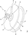
- the Fig. 1 to Fig. 3 show a device 10 for sealing a recess 104 in an object 102.
- the device 10 comprises a pressure disk 12 and a stop disk 14, wherein a deformation body 16 is arranged between the pressure disk 12 and the stop disk 14.
- a tensioning device 18 extends along a central axis x through the pressure disk 12, the deformation body 16 and the stop disk 14 and has a height H.
- the pressure disk 12 has a contact surface 28 for the deformation body 16.
- the stop disk 14 has a contact surface 30 for the deformation body 16.
- the contact surface 30 of the stop disk 14 and the contact surface 28 of the pressure disk 12 can be pressed against the deformation body 16 by means of the tensioning device 18.
- the deformation body 16 is formed of a synthetic rubber material and elastically deformable.
- the pressure plate 12 and the Stop disk 14 are formed of a dimensionally stable material, for example of metal, a metal alloy or a dimensionally stable plastic.
- a deformation of the deformation body 16 is caused by which the deformation body 16 expands in the radial direction. If the deformation body 16 is inserted into a recess 104 in an object 102, the radial extent of the deformation body 16 seals the recess 104. The deformation of the deformation body 16 can therefore also compensate for large tolerance fluctuations due to irregular or unclean production.
- the device 10 can therefore also be referred to as a pinch seal.
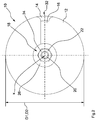
- the pressure disk 12 has a slot-shaped recess 32, which extends from an outer edge 34 of the pressure disk 12 into a central region of the pressure disk 12.
- the slot-shaped recess 32 allows a substantial simplification of the assembly process, as with respect to the Fig. 4a to Fig. 4c described below.
- the stop disk 14 and the deformation body 16 each have a central through hole for the tensioning device 18.
- the pressure disk 12, the stop disk 14 and the deformation body 16 each have a round cross-section.
- the diameter D1 of the thrust washer 12 and the diameter D2 of the stop disc 14 are identical.
- the deformation body 16 has a smaller diameter D3 than the pressure disk 12 and the stop disk 14.
- the tensioning device 18 comprises an elongate element 20 designed as a round-head screw with an external thread. On the side facing away from the deformation body 16 of the stopper plate 14, a through-hole of the stopper plate 14 superior end portion 36 of the elongate member 20 is arranged. The end portion 36 of the elongated element 20 is designed as a screw head. Furthermore, the clamping device 18 comprises a clamping body 22 designed as a nut with an internal thread. The external thread of the elongate element 20 corresponds to the internal thread of the clamping body 22. Between the pressure plate 12 and the clamping body 22, a washer 26 is arranged.
- the distance between the clamping body 22 and the end portion 36 of the elongate member 20 is reduced, so that the distance between the pressure plate 12 and the stop plate 14 is reduced.
- the reduction in distance between the thrust washer 12 and the stopper plate 14 causes the deformation of the deformation body 16.
- the tensioning device 18 has an anti-twist device 38.
- the anti-rotation device 38 prevents a rotation of the elongate element 20 relative to the stop disk 14 due to a positive connection between the elongate element 20 and the stop disk 14 Due to the frictional force between the stop disk 14 and the portion of the object 102 surrounding the recess 104, a rotational movement of the elongate element 20 when the clamping body 22 is turned up is essentially avoided.
- a nut lock 24 is screwed from two individual nuts on the external thread of the elongated member 20.
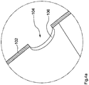
- the Fig. 4a to Fig. 4c 10 illustrates an assembly process of a device 10 for sealing a recess 104 in an object 102, wherein the object 102 having the recess 104 and the device 10 for sealing the recess 104 in the object 102 form an assembly 100.
- the Fig. 4a shows a formed as a through hole circular recess 104 in a plate-like portion of an object 102nd
- the deformation body 16 is inserted into the recess 104.
- the deformation body 16 is connected to the stop disk 14 via the tensioning device 18.
- the contact surface 30 of the stopper disc 14 is greater than the outer surface of the deformation body 16 in contact with the contact surface 30 of the stopper plate 14 and larger than the recess 104 in the object 102 and the clamping body 22 designed as a nut is already partially screwed is the deformation body 16 is secured against falling out of the recess 104, so that no additional stabilization of the deformation body 16 by an installer is necessary.
- the slot-shaped recess 32 in the thrust washer 12 allows the typewriter to be inserted between the deformation body 16 and the clamping body 22 during the assembly process of the device 10. Because the thrust washer 12 can be inserted between the deformation body 16 and the tensioning body 22, there is no need for disassembly of the tensioning body 22 securing the deformation body 16. Thus, the assembly is considerably simplified and allows one-hand assembly.
- the contact surface 28 of the pressure plate 12 is also greater than the outer surface of the deformation body 16 in contact with the contact surface 28 of the pressure plate 12 and larger than the recess 104 in the object 102.
- the pressure plate 12 before pressing the deformation body 16 also for a safeguard against falling out.
- a uniform stress distribution and thus a uniform deformation of the deformation body 16 is achieved by the excess of the thrust washer 12 and the stopper plate 14 with respect to the deformation body 16, so that by the compression circumferential contact area between the deformation body 16 and the wall 106 of the recess 104 forms.
- the illustrated assembly 100 may be, for example, a component of a sowing container of a seeder.
Landscapes
- Engineering & Computer Science (AREA)
- General Engineering & Computer Science (AREA)
- Mechanical Engineering (AREA)
- Gasket Seals (AREA)
Abstract
Description
- Die Erfindung betrifft eine Vorrichtung zum Abdichten einer Ausnehmung in einem Objekt nach dem Oberbegriff des Patentanspruchs 1 und eine Baugruppe nach dem Oberbegriff des Patentanspruchs 12.
- Bei einer Vielzahl von Baugruppen besteht die Notwendigkeit Ausnehmungen, wie zum Beispiel Bohrungen, in einem Objekt abzudichten. Das Objekt kann dabei beispielsweise eine Platte oder ein Gehäusesegment sein.
- Abhängig von dem Einsatzgebiet der jeweiligen Baugruppe kann dabei ein flüssigkeits- und/oder gasdichtes Abdichten gewünscht sein, beispielsweise um Material oder elektronische Bauteile vor Feuchtigkeit zu schützen.
- Aufgrund von Toleranzschwankungen oder unsauber durchgeführten Fertigungsvorgängen kann es zu teilweise erheblichen Maß- und/oder Formunterschieden bei den abzudichtenden Ausnehmungen kommen, sodass in Frage kommende Abdichtvorrichtungen zum Ausgleich derartiger Unregelmäßigkeiten geeignet sein müssen.
- Aus der Druckschrift
US 2003/0014905 A1 ist beispielsweise eine Bohrlochabdeckung bekannt, bei welcher ein in die Ausnehmung einzusetzender Deformationskörper mittels eines Scheibenpaares derart verformbar ist, dass der Außenmantel des Deformationskörpers gegen die Innenkontur des Bohrlochs gepresst wird, sodass eine Dichtwirkung erzielt wird. - Diese und andere bekannte Lösungen zum Abdichten von Ausnehmungen haben jedoch den Nachteil, dass die Montage vergleichsweise aufwendig ist und einzelne Teile der Vorrichtung während der Montage temporär gehalten werden müssen, damit weitere Teile bestimmungsgemäß positioniert und fixiert werden können. Eine Einhandmontage ist aus diesem Grund regelmäßig nicht möglich. Teilweise sind für die Montage sogar mehrere Monteure notwendig.
- Die der Erfindung zugrundeliegende Aufgabe besteht somit darin, den Montagevorgang von Abdichtvorrichtungen für Ausnehmungen zu vereinfachen.
- Die Aufgabe wird gelöst durch eine Vorrichtung der eingangs genannten Art, wobei eine Druckscheibe der Vorrichtung mittels eines Spannkörpers einer Spanneinrichtung gegen einen Deformationskörper pressbar ist. Erfindungsgemäß ist die Druckscheibe derart ausgebildet, dass die Druckscheibe während des Montageprozesses der Vorrichtung zwischen den Deformationskörper und den Spannkörper einsetzbar ist.
- Die Erfindung macht sich die Erkenntnis zunutze, dass eine Einhandmontage möglich ist, wenn der Deformationskörper samt der Spanneinrichtung während des Montageprozesses der Vorrichtung positionsstabil in der Ausnehmung angeordnet werden kann und ein anschließendes Einsetzen der Druckscheibe zwischen den Deformationskörper und den Spannkörper der Spanneinrichtung möglich ist. Dadurch, dass die Druckscheibe zwischen den Deformationskörper und den Spannkörper einsetzbar ist, kann der Deformationskörper vor dem Einsetzen der Druckscheibe mittels des Spannkörpers der Spanneinrichtung vor dem Herausfallen gesichert werden. Ein zusätzliches Festhalten des Deformationskörpers vor oder während des Einsetzens der Druckscheibe ist nicht länger notwendig. Demnach erlaubt die Vorrichtung eine Einhandmontage, sodass der Montagevorgang wesentlich vereinfacht ist.
- Die Vorrichtung zum Abdichten der Ausnehmung kann auch als Quetschdichtung bezeichnet werden. Durch die Formveränderung des Deformationskörpers können große Toleranzschwankungen aufgrund unregelmäßiger oder unsauberer Fertigung ohne Weiteres ausgeglichen werden.
- In einer bevorzugten Ausführungsform der erfindungsgemäßen Vorrichtung weist die Druckscheibe eine schlitzförmige Ausnehmung auf, welche sich vorzugsweise von einer Außenkante der Druckscheibe bis in einen Mittelbereich der Druckscheibe erstreckt. Durch die schlitzförmige Ausnehmung kann die Druckscheibe zwischen den Deformationskörper und den Spannkörper geschoben werden, wobei ein Teil der Spanneinrichtung während des Einsetzens innerhalb der schlitzförmigen Ausnehmung der Druckscheibe angeordnet ist. Nachdem die Druckscheibe zwischen den Deformationskörper und den Spannkörper eingesetzt worden ist, erstreckt sich ein Teil der Spanneinrichtung durch den Mittelbereich der schlitzförmigen Ausnehmung.
- Außerdem ist eine erfindungsgemäße Vorrichtung bevorzugt, bei welcher die Spanneinrichtung ein längliches Element mit einem Außengewinde aufweist, wobei der Spannkörper ein mit dem Außengewinde korrespondierendes Innengewinde aufweist. Das längliche Element kann beispielsweise eine Schraube oder eine Gewindestange sein. Alternativ kann das längliche Element ein Bestandteil einer Schraube oder einer Gewindestange sein. Die Schraube kann eine Flachrundschraube sein. Der Spannkörper kann beispielsweise als Mutter ausgebildet sein. Zwischen der Druckscheibe und dem Spannkörper kann eine Unterlegscheibe angeordnet sein.
- In einer weiteren bevorzugten Ausführungsform weist die erfindungsgemäße Vorrichtung eine Anschlagsscheibe auf, welche eine Kontaktfläche für den Deformationskörper aufweist. Die Kontaktfläche der Anschlagsscheibe ist mittels der Spanneinrichtung gegen den Deformationskörper pressbar. Insbesondere sind die Druckscheibe und die Anschlagsscheibe im montierten Zustand der Vorrichtung auf gegenüberliegenden Seiten des Deformationskörpers angeordnet. Vorzugsweise weisen der Deformationskörper, die Druckscheibe und/oder die Anschlagsscheibe eine im Wesentlichen kreisförmige Grundform auf. Vorzugsweise überragt die Druckscheibe und/oder die Anschlagsscheibe den Deformationskörper im montierten Zustand der Vorrichtung.
- In einer Weiterbildung der erfindungsgemäßen Vorrichtung weist die Anschlagsscheibe ein Durchgangsloch auf, durch welches sich das längliche Element der Spanneinrichtung erstreckt. Das Durchgangsloch ist vorzugsweise in einem Zentralbereich der Anschlagsscheibe angeordnet und/oder weist einen kreisrunden Querschnitt auf. Vorzugsweise ist der Mittelbereich der schlitzförmigen Ausnehmung in der Druckscheibe im montierten Zustand der Vorrichtung mit dem Durchgangsloch der Anschlagsscheibe in Deckung gebracht. Somit kann sich das längliche Element der Spanneinrichtung sowohl durch den Deformationskörper als auch durch die Druckscheibe und die Anschlagsscheibe erstrecken.
- Vorteilhaft ist außerdem eine erfindungsgemäße Vorrichtung, bei welcher auf der dem Deformationskörper abgewandten Seite der Anschlagsscheibe ein das Durchgangsloch überragender Endabschnitt des länglichen Elements angeordnet ist. Der Endabschnitt des länglichen Elements ist vorzugsweise als Schraubenkopf ausgebildet. Insbesondere weist der Endabschnitt eine im Wesentlichen ringförmige Kontaktfläche auf, welche im montierten Zustand der Vorrichtung mit der dem Deformationskörper gegenüberliegenden Seite der Anschlagsscheibe in Kontakt steht.
- In einer Weiterbildung der erfindungsgemäßen Vorrichtung weist die Spanneinrichtung eine Verdrehsicherung auf. Die Verdrehsicherung gewährleistet, dass eine bei der Montage auftretende Momentenbelastung an der Spanneinrichtung nicht zu einem Verdrehen der Spanneinrichtung führt. Insbesondere, wenn das längliche Element als Schraube und der Spannkörper als Mutter ausgebildet ist, kann durch die Verdrehsicherung ein Mitdrehen der Schraube beim Eindrehen der Mutter effektiv vermieden werden. Insbesondere wird die Verdrehsicherung durch einen Formschluss umgesetzt. Beispielsweise weist das längliche Element einen Sicherungsabschnitt auf, welcher verdrehsicher mit dem Deformationskörper und/oder der Anschlagsscheibe koppelbar ist. Beispielsweise weist das längliche Element in dem Bereich des Sicherungsabschnitts eine sechseckige Grundform auf, welche in eine korrespondierende sechseckige Ausnehmung in dem Deformationskörper und/oder in der Anschlagsscheibe einsetzbar ist, sodass eine Verdrehung des länglichen Elements gegenüber dem Deformationskörper und/oder der Anschlagsscheibe vermieden wird.
- Darüber hinaus ist eine erfindungsgemäße Vorrichtung vorteilhaft, bei welcher der Deformationskörper elastisch und/oder plastisch verformbar ist. Durch die elastische Verformbarkeit des Deformationskörpers kann die Vorrichtung beschädigungsfrei und wiederverwendbar aus der Ausnehmung in dem Objekt entfernt werden. In anderen Anwendungsfällen kann die plastische Verformbarkeit des Deformationskörpers vorteilhaft sein, beispielsweise wenn eine dauerhafte Abdichtung der Ausnehmung in dem Objekt gewünscht ist.
- Darüber hinaus ist eine erfindungsgemäße Vorrichtung bevorzugt, bei welcher der Deformationskörper teilweise oder vollständig aus einem Gummimaterial, insbesondere aus einem synthetischen Gummimaterial, ausgebildet ist. Der Deformationskörper weist vorzugsweise ein zentrales Durchgangsloch und/oder einen runden Querschnitt auf. Das Gummimaterial und/oder deren Zusammensetzung kann in Abhängigkeit der notwendigen Deformationseigenschaften des Deformationskörpers ausgewählt werden. Die Druckscheibe und/oder die Anschlagsscheibe können aus Metall, einer Metalllegierung oder einem formstabilen Kunststoff ausgebildet sein.
- Weiterhin ist eine erfindungsgemäße Vorrichtung vorteilhaft, bei welcher die Kontaktfläche der Druckscheibe größer als die mit der Kontaktfläche der Druckscheibe in Kontakt stehende Außenfläche des Deformationskörpers ist. Alternativ oder zusätzlich ist die Kontaktfläche der Druckscheibe größer als die Ausnehmung in dem Objekt. Dadurch, dass die Kontaktfläche der Druckscheibe größer als die mit der Kontaktfläche der Druckscheibe in Kontakt stehende Außenfläche des Deformationskörpers ist, kann eine gleichmäßige Druckkraft über die gesamte Außenfläche des Deformationskörpers erreicht werden. Hieraus resultiert eine gleichmäßige Verformung des Deformationskörpers bei Druckbeanspruchung, sodass eine allseitige Dichtwirkung durch den Deformationskörper gewährleistet wird.
- Darüber hinaus ist eine erfindungsgemäße Vorrichtung vorteilhaft, bei welcher die Kontaktfläche der Anschlagsscheibe größer als die mit der Kontaktfläche der Anschlagsscheibe in Kontakt stehende Außenfläche des Deformationskörpers ist. Alternativ oder zusätzlich ist die Kontaktfläche der Anschlagsscheibe größer als die Ausnehmung in dem Objekt. Wenn die Kontaktfläche der Anschlagsscheibe größer als die Ausnehmung in dem Objekt ist, kann die Anschlagsscheibe gemeinsam mit dem Deformationskörper und der Spanneinrichtung in die Ausnehmung eingesetzt werden, wobei die Anschlagsscheibe ein Herausfallen dieser Komponenten aus der Ausnehmung verhindert. In diesem Fall ergibt sich vorzugsweise eine im Wesentlichen ringförmige Kontaktfläche zwischen der Anschlagsscheibe und dem die abzudichtende Ausnehmung aufweisenden Objekt.
- Die der Erfindung zugrundeliegende Aufgabe wird ferner durch eine Baugruppe der eingangs genannten Art gelöst, wobei die Vorrichtung zum Abdichten der Ausnehmung der erfindungsgemäßen Baugruppe nach einer der vorstehend beschriebenen Ausführungsformen ausgebildet ist. Hinsichtlich der Vorteile und Modifikationen der erfindungsgemäßen Baugruppe wird zunächst auf die Vorteile und Modifikationen der erfindungsgemäßen Vorrichtung zum Abdichten einer Ausnehmung in einem Objekt verwiesen.
- In einer bevorzugten Ausführungsform ist die erfindungsgemäße Baugruppe als Säbehälter einer Sämaschine ausgebildet. Das sich innerhalb des Säbehälters befindliche Saatgut wird mittels der Vorrichtung effektiv vor Feuchtigkeit geschützt. Somit wird beispielsweise ein Verklumpen des Saatguts vor der Ausbringung vermieden. Außerdem sorgt die flache und runde Ausführung der Anschlagscheibe dafür, dass das Saatgut nahezu ungestört über die Behälterwände nachrutschen kann.
- Vorzugsweise ist das Objekt teilweise oder vollständig, jedoch zumindest in dem Bereich der Ausnehmung aus einem Kunststoff, insbesondere aus Polyethylen ausgebildet. Beispielsweise kann das Objekt in dem Bereich der Ausnehmung eine Wandstärke zwischen 5 und 20 mm, insbesondere eine Wandstärke von etwa 11 mm, aufweisen.
- Weitere Einzelheiten der Erfindung sind der Figurenbeschreibung und den Zeichnungen zu entnehmen. Es zeigen
- Fig. 1
- ein Ausführungsbeispiel der erfindungsgemäßen Vorrichtung in einer perspektivischen Darstellung;
- Fig. 2
- die in der
Fig. 1 dargestellte Vorrichtung in einer Draufsicht; - Fig. 3
- die in der
Fig. 1 dargestellte Vorrichtung in einer Seitenansicht; - Fig. 4a
- eine Ausnehmung in einem Objekt in einer Schnittdarstellung;
- Fig. 4b
- einen Montagezustand einer in die Ausnehmung aus der
Fig. 4a eingesetzten erfindungsgemäßen Vorrichtung in einer Schnittdarstellung; und - Fig. 4c
- die in der
Fig. 4b dargestellte Vorrichtung nach Abschluss der Montage in einer Schnittdarstellung. - Die
Fig. 1 bis Fig. 3 zeigen eine Vorrichtung 10 zum Abdichten einer Ausnehmung 104 in einem Objekt 102. - Die Vorrichtung 10 umfasst eine Druckscheibe 12 und eine Anschlagsscheibe 14, wobei zwischen der Druckscheibe 12 und der Anschlagsscheibe 14 ein Deformationskörper 16 angeordnet ist. Eine Spanneinrichtung 18 erstreckt sich entlang einer Mittelachse x durch die Druckscheibe 12, den Deformationskörper 16 und die Anschlagsscheibe 14 und weist eine Höhe H auf.
- Die Druckscheibe 12 weist eine Kontaktfläche 28 für den Deformationskörper 16 auf. Die Anschlagsscheibe 14 weist eine Kontaktfläche 30 für den Deformationskörper 16 auf. Die Kontaktfläche 30 der Anschlagsscheibe 14 und die Kontaktfläche 28 der Druckscheibe 12 sind mittels der Spanneinrichtung 18 gegen den Deformationskörper 16 pressbar.
- Der Deformationskörper 16 ist aus einem synthetischen Gummimaterial ausgebildet und elastisch verformbar. Die Druckscheibe 12 und die Anschlagsscheibe 14 sind aus einem formstabilen Material ausgebildet, beispielsweise aus Metall, einer Metalllegierung oder einem formstabilen Kunststoff.
- Durch das Pressen der Kontaktflächen 28, 30 gegen den Deformationskörper 16 wird eine Verformung des Deformationskörpers 16 hervorgerufen, durch welche sich der Deformationskörper 16 in radialer Richtung ausdehnt. Wenn der Deformationskörper 16 in eine Ausnehmung 104 in einem Objekt 102 eingesetzt ist, erfolgt durch die radiale Ausdehnung des Deformationskörpers 16 eine Abdichtung der Ausnehmung 104. Durch die Verformung des Deformationskörpers 16 können somit auch große Toleranzschwankungen aufgrund von unregelmäßiger oder unsauberer Fertigung ausgeglichen werden. Die Vorrichtung 10 kann also auch als Quetschdichtung bezeichnet werden.
- Die Druckscheibe 12 weist eine schlitzförmige Ausnehmung 32 auf, welche sich von einer Außenkante 34 der Druckscheibe 12 bis in einen Mittelbereich der Druckscheibe 12 erstreckt. Die schlitzförmige Ausnehmung 32 erlaubt eine wesentliche Vereinfachung des Montageprozesses, wie mit Bezug auf die
Fig. 4a bis Fig. 4c nachfolgend beschrieben ist. - Die Anschlagsscheibe 14 und der Deformationskörper 16 weisen jeweils ein zentrales Durchgangsloch für die Spanneinrichtung 18 auf. Die Druckscheibe 12, die Anschlagsscheibe 14 und der Deformationskörper 16 weisen jeweils einen runden Querschnitt auf. Der Durchmesser D1 der Druckscheibe 12 und der Durchmesser D2 der Anschlagsscheibe 14 stimmen überein. Der Deformationskörper 16 weist einen kleineren Durchmesser D3 als die Druckscheibe 12 und die Anschlagsscheibe 14 auf.
- Die Spanneinrichtung 18 umfasst ein längliches als Flachrundschraube ausgebildetes Element 20 mit einem Außengewinde. Auf der dem Deformationskörper 16 abgewandten Seite der Anschlagsscheibe 14 ist ein das Durchgangsloch der Anschlagsscheibe 14 überragender Endabschnitt 36 des länglichen Elements 20 angeordnet. Der Endabschnitt 36 des länglichen Elements 20 ist als Schraubenkopf ausgebildet. Ferner umfasst die Spanneinrichtung 18 einen als Mutter ausgebildeten Spannkörper 22 mit einem Innengewinde. Das Außengewinde des länglichen Elements 20 korrespondiert mit dem Innengewinde des Spannkörpers 22. Zwischen der Druckscheibe 12 und dem Spannkörper 22 ist eine Unterlegscheibe 26 angeordnet.
- Beim Aufdrehen des Spannkörpers 22 auf das längliche Element 20 wird der Abstand zwischen dem Spannkörper 22 und dem Endabschnitt 36 des länglichen Elements 20 verringert, sodass auch der Abstand zwischen der Druckscheibe 12 und der Anschlagsscheibe 14 verringert wird. Die Abstandsverringerung zwischen der Druckscheibe 12 und der Anschlagsscheibe 14 verursacht die Verformung des Deformationskörpers 16.
- Damit ein komfortables Aufdrehen des Spannkörpers 22 auf das längliche Element 20 erfolgen kann, verfügt die Spanneinrichtung 18 über eine Verdrehsicherung 38. Die Verdrehsicherung 38 verhindert durch einen Formschluss zwischen dem länglichen Element 20 und der Anschlagsscheibe 14 eine Verdrehung des länglichen Elements 20 gegenüber der Anschlagsscheibe 14. Aufgrund der Reibkraft zwischen der Anschlagsscheibe 14 und dem die Ausnehmung 104 umgebenden Abschnitt des Objekts 102 wird eine Drehbewegung des länglichen Elements 20 beim Aufdrehen des Spannkörpers 22 im Wesentlichen vermieden.
- Außerdem ist auf das Außengewinde des länglichen Elements 20 eine Muttersicherung 24 aus zwei Einzelmuttern aufgeschraubt.
- Die
Fig. 4a bis Fig. 4c zeigen einen Montageprozess einer Vorrichtung 10 zum Abdichten einer Ausnehmung 104 in einem Objekt 102, wobei das die Ausnehmung 104 aufweisende Objekt 102 und die Vorrichtung 10 zum Abdichten der Ausnehmung 104 in dem Objekt 102 eine Baugruppe 100 ausbilden. - Die
Fig. 4a zeigt eine als Durchgangloch ausgebildete kreisrunde Ausnehmung 104 in einem plattenartigen Abschnitt eines Objekts 102. - Wie die
Fig. 4b zeigt, ist zunächst der Deformationskörper 16 in die Ausnehmung 104 einzusetzen. Der Deformationskörper 16 ist über die Spanneinrichtung 18 mit der Anschlagsscheibe 14 verbunden. - Dadurch, dass die Kontaktfläche 30 der Anschlagsscheibe 14 größer als die mit der Kontaktfläche 30 der Anschlagsscheibe 14 in Kontakt stehende Außenfläche des Deformationskörpers 16 und größer als die Ausnehmung 104 in dem Objekt 102 ist und der als Mutter ausgebildete Spannkörper 22 bereits teilweise aufgeschraubt ist, wird der Deformationskörper 16 vor dem Herausfallen aus der Ausnehmung 104 gesichert, sodass keine zusätzliche Stabilisierung des Deformationskörpers 16 durch einen Monteur notwendig ist.
- Die schlitzförmige Ausnehmung 32 in der Druckscheibe 12 erlaubt es, dass die Druckschreibe während des Montageprozesses der Vorrichtung 10 zwischen den Deformationskörper 16 und den Spannkörper 22 einsetzbar ist. Dadurch, dass die Druckscheibe 12 zwischen den Deformationskörper 16 und den Spannkörper 22 einsetzbar ist, bedarf es auch keiner Demontage des den Deformationskörper 16 sichernden Spannkörpers 22. Somit wird die Montage wesentlich vereinfacht und eine Einhandmontage ermöglicht.
- In der dargestellten Ausführungsform ist die Kontaktfläche 28 der Druckscheibe 12 ebenfalls größer als die mit der Kontaktfläche 28 der Druckscheibe 12 in Kontakt stehende Außenfläche des Deformationskörpers 16 und größer als die Ausnehmung 104 in dem Objekt 102. Somit sorgt die Druckscheibe 12 vor dem Verpressen des Deformationskörpers 16 ebenfalls für eine Sicherung gegen Herausfallen.
- Außerdem wird durch das Übermaß der Druckscheibe 12 und der Anschlagsscheibe 14 in Bezug auf den Deformationskörper 16 eine gleichmäßige Spannungsverteilung und somit eine gleichmäßige Deformation des Deformationskörpers 16 erreicht, sodass sich durch die Verpressung ein umlaufender Kontaktbereich zwischen dem Deformationskörper 16 und der Bewandung 106 der Ausnehmung 104 ausbildet.
- Die dargestellte Baugruppe 100 kann beispielsweise ein Bestandteil eines Säbehälters einer Sämaschine sein.
-
- 10
- Vorrichtung
- 12
- Druckscheibe
- 14
- Anschlagsscheibe
- 16
- Deformationskörper
- 18
- Spanneinrichtung
- 20
- längliches Element
- 22
- Spannkörper
- 24
- Muttersicherung
- 26
- Unterlegscheibe
- 28
- Kontaktfläche
- 30
- Kontaktfläche
- 32
- schlitzförmige Ausnehmung
- 34
- Außenkante
- 36
- Endabschnitt
- 38
- Verdrehsicherung
- 100
- Baugruppe
- 102
- Objekt
- 104
- Ausnehmung
- 106
- Bewandung
- D1-D3
- Durchmesser
- H
- Höhe
- x
- Mittelachse
Claims (13)
- Vorrichtung (10) zum Abdichten einer Ausnehmung (104) in einem Objekt (102), mit- einem Deformationskörper (16), welcher dazu eingerichtet ist, in die Ausnehmung (104) eingesetzt zu werden;- einer Druckscheibe (12), welche eine Kontaktfläche (28) für den Deformationskörper (16) aufweist; und- einer sich durch den Deformationskörper (16) erstreckenden Spanneinrichtung (18),wobei die Kontaktfläche (28) der Druckscheibe (12) mittels eines Spannkörpers (22) der Spanneinrichtung (18) gegen den Deformationskörper (16) pressbar ist,
dadurch gekennzeichnet, dass die Druckscheibe (12) derart ausgebildet ist, dass die Druckschreibe während des Montageprozesses der Vorrichtung (10) zwischen den Deformationskörper (16) und den Spannkörper (22) einsetzbar ist. - Vorrichtung (10) nach Anspruch 1,
dadurch gekennzeichnet, dass die Druckscheibe (12) eine schlitzförmige Ausnehmung (32) aufweist, welche sich vorzugsweise von einer Außenkante (34) der Druckscheibe (12) bis in einen Mittelbereich der Druckscheibe (12) erstreckt. - Vorrichtung (10) nach Anspruch 1 oder 2,
dadurch gekennzeichnet, dass die Spanneinrichtung (18) ein längliches Element (20) mit einem Außengewinde aufweist, wobei der Spannkörper (22) ein mit dem Außengewinde korrespondierendes Innengewinde aufweist. - Vorrichtung (10) nach einem der vorstehenden Ansprüche,
gekennzeichnet durch eine Anschlagsscheibe (14), welche eine Kontaktfläche (30) für den Deformationskörper (16) aufweist, wobei die Kontaktfläche (30) der Anschlagsscheibe (14) mittels der Spanneinrichtung (18) gegen den Deformationskörper (16) pressbar ist. - Vorrichtung (10) nach Anspruch 4,
dadurch gekennzeichnet, dass die Anschlagsscheibe (14) ein Durchgangsloch aufweist, durch welches sich das längliche Element (20) der Spanneinrichtung (18) erstreckt. - Vorrichtung (10) nach Anspruch 4 oder 5,
dadurch gekennzeichnet, dass auf der dem Deformationskörper (16) abgewandten Seite der Anschlagsscheibe (14) ein das Durchgangsloch überragender Endabschnitt (36) des länglichen Elements (20) angeordnet ist. - Vorrichtung (10) nach einem der vorstehenden Ansprüche,
dadurch gekennzeichnet, dass die Spanneinrichtung (18) eine Verdrehsicherung (38) aufweist. - Vorrichtung (10) nach einem der vorstehenden Ansprüche,
dadurch gekennzeichnet, dass der Deformationskörper (16) elastisch und/oder plastisch verformbar ist. - Vorrichtung (10) nach einem der vorstehenden Ansprüche,
dadurch gekennzeichnet, dass der Deformationskörper (16) teilweise oder vollständig aus einem Gummimaterial, insbesondere aus einem synthetischen Gummimaterial, ausgebildet ist. - Vorrichtung (10) nach einem der vorstehenden Ansprüche,
dadurch gekennzeichnet, dass die Kontaktfläche (28) der Druckscheibe (12) größer als die mit der Kontaktfläche (28) der Druckscheibe (12) in Kontakt stehende Außenfläche des Deformationskörpers (16) und/oder größer als die Ausnehmung (104) in dem Objekt (102) ist. - Vorrichtung (10) nach einem der Ansprüche 4 bis 10,
dadurch gekennzeichnet, dass die Kontaktfläche (30) der Anschlagsscheibe (14) größer als die mit der Kontaktfläche (30) der Anschlagsscheibe (14) in Kontakt stehende Außenfläche des Deformationskörpers (16) und/oder größer als die Ausnehmung (104) in dem Objekt (102) ist. - Baugruppe (100), mit- einem eine Ausnehmung (104) aufweisenden Objekt (102), und- einer Vorrichtung (10) zum Abdichten der Ausnehmung (104) in dem Objekt (102);dadurch gekennzeichnet, dass die Vorrichtung (10) nach einem der vorstehenden Ansprüche ausgebildet ist.
- Baugruppe (100) nach Anspruch 12,
dadurch gekennzeichnet, dass die Baugruppe (100) als Säbehälter einer Sämaschine ausgebildet ist.
Priority Applications (1)
| Application Number | Priority Date | Filing Date | Title |
|---|---|---|---|
| PL19155885T PL3524868T3 (pl) | 2018-02-08 | 2019-02-07 | Urządzenie do uszczelniania wgłębienia w przedmiocie |
Applications Claiming Priority (1)
| Application Number | Priority Date | Filing Date | Title |
|---|---|---|---|
| DE102018102815.6A DE102018102815A1 (de) | 2018-02-08 | 2018-02-08 | Vorrichtung zum Abdichten einer Ausnehmung in einem Objekt |
Publications (2)
| Publication Number | Publication Date |
|---|---|
| EP3524868A1 true EP3524868A1 (de) | 2019-08-14 |
| EP3524868B1 EP3524868B1 (de) | 2021-12-01 |
Family
ID=65408880
Family Applications (1)
| Application Number | Title | Priority Date | Filing Date |
|---|---|---|---|
| EP19155885.7A Active EP3524868B1 (de) | 2018-02-08 | 2019-02-07 | Vorrichtung zum abdichten einer ausnehmung in einem objekt |
Country Status (4)
| Country | Link |
|---|---|
| EP (1) | EP3524868B1 (de) |
| DE (1) | DE102018102815A1 (de) |
| DK (1) | DK3524868T3 (de) |
| PL (1) | PL3524868T3 (de) |
Citations (4)
| Publication number | Priority date | Publication date | Assignee | Title |
|---|---|---|---|---|
| US2993616A (en) * | 1959-06-04 | 1961-07-25 | Columbus Bolt & Forging Compan | Expansible closure |
| US3365093A (en) * | 1966-07-13 | 1968-01-23 | William P. Malenke | Hole plugging means |
| US3673913A (en) * | 1970-09-04 | 1972-07-04 | Southco | Panel fastener with expandable sleeve |
| US20030014905A1 (en) | 2000-08-29 | 2003-01-23 | Baker Jerry G. | Tamper resistant non-corrosive bore hole cover assembly |
-
2018
- 2018-02-08 DE DE102018102815.6A patent/DE102018102815A1/de not_active Withdrawn
-
2019
- 2019-02-07 DK DK19155885.7T patent/DK3524868T3/da active
- 2019-02-07 EP EP19155885.7A patent/EP3524868B1/de active Active
- 2019-02-07 PL PL19155885T patent/PL3524868T3/pl unknown
Patent Citations (4)
| Publication number | Priority date | Publication date | Assignee | Title |
|---|---|---|---|---|
| US2993616A (en) * | 1959-06-04 | 1961-07-25 | Columbus Bolt & Forging Compan | Expansible closure |
| US3365093A (en) * | 1966-07-13 | 1968-01-23 | William P. Malenke | Hole plugging means |
| US3673913A (en) * | 1970-09-04 | 1972-07-04 | Southco | Panel fastener with expandable sleeve |
| US20030014905A1 (en) | 2000-08-29 | 2003-01-23 | Baker Jerry G. | Tamper resistant non-corrosive bore hole cover assembly |
Also Published As
| Publication number | Publication date |
|---|---|
| DE102018102815A1 (de) | 2019-08-08 |
| PL3524868T3 (pl) | 2022-01-31 |
| DK3524868T3 (da) | 2022-01-24 |
| EP3524868B1 (de) | 2021-12-01 |
Similar Documents
| Publication | Publication Date | Title |
|---|---|---|
| DE894792C (de) | Gewinde-Sperrvorrichtung | |
| DE19839342A1 (de) | Gerätesteckverbinder | |
| DE69712726T2 (de) | Sicherungsmutter | |
| EP3286440B2 (de) | Vorrichtung zum festlegen an einem bauteil | |
| DE102016209846A1 (de) | Keilsicherungsmutteranordnung | |
| DE102013009650A1 (de) | Ventil | |
| DE102019110701A1 (de) | Halteelement zum halten eines zu befestigenden bauteils und haltesystem mit einem solchen | |
| DE102011002996A1 (de) | Kraftstoffeinspritzventil mit verbessertem Hochdruckanschluss | |
| DE102014224932A1 (de) | Haltevorrichtung für eine Schraubenmutter sowie Baueinheit mit einer solchen Haltevorrichtung | |
| DE202011109172U1 (de) | Schraubverbindung, Brille | |
| EP3371861B1 (de) | Zündkerze mit erhöhtem anzugsdrehmoment | |
| DE102004014593B4 (de) | Vorrichtung zum Befestigung an einem mit einem Gewindebolzen versehenen Trägerteil | |
| DE102017105687A1 (de) | Sicherungselement für eine Dünnschaftschraube und Befestigungssystem | |
| EP3524868B1 (de) | Vorrichtung zum abdichten einer ausnehmung in einem objekt | |
| WO2016012224A1 (de) | Hochdruckanschlussvorrichtung | |
| DE102009052108A1 (de) | Elektrische Steckverbinder mit Schnellbefestigungs-Vorrichtung | |
| DE102016115709B4 (de) | Befestigungsvorrichtung | |
| DE102004048436A1 (de) | Steckhülse zur Befestigung eines Bauteils in einer Bohrung | |
| DE102015210516A1 (de) | Befestigungssystem mit Dünnschaftschraube und Sicherungselement | |
| DE102013226768A1 (de) | Mutter | |
| DE2620996A1 (de) | Verriegelungsmutter | |
| DE60017342T2 (de) | Befestigungsvorrichtung für Profile | |
| DE202008015523U1 (de) | Verschraubung | |
| DE102017218911B4 (de) | Gehäuse, damit ausgestatteter Drehantrieb und zugehöriges Herstellungsverfahren | |
| DE102015121479A1 (de) | Verbindungselement |
Legal Events
| Date | Code | Title | Description |
|---|---|---|---|
| PUAI | Public reference made under article 153(3) epc to a published international application that has entered the european phase |
Free format text: ORIGINAL CODE: 0009012 |
|
| STAA | Information on the status of an ep patent application or granted ep patent |
Free format text: STATUS: THE APPLICATION HAS BEEN PUBLISHED |
|
| AK | Designated contracting states |
Kind code of ref document: A1 Designated state(s): AL AT BE BG CH CY CZ DE DK EE ES FI FR GB GR HR HU IE IS IT LI LT LU LV MC MK MT NL NO PL PT RO RS SE SI SK SM TR |
|
| AX | Request for extension of the european patent |
Extension state: BA ME |
|
| STAA | Information on the status of an ep patent application or granted ep patent |
Free format text: STATUS: REQUEST FOR EXAMINATION WAS MADE |
|
| 17P | Request for examination filed |
Effective date: 20200212 |
|
| RBV | Designated contracting states (corrected) |
Designated state(s): AL AT BE BG CH CY CZ DE DK EE ES FI FR GB GR HR HU IE IS IT LI LT LU LV MC MK MT NL NO PL PT RO RS SE SI SK SM TR |
|
| RAP3 | Party data changed (applicant data changed or rights of an application transferred) |
Owner name: AMAZONEN-WERK H. DREYER SE & CO. KG |
|
| RAP3 | Party data changed (applicant data changed or rights of an application transferred) |
Owner name: AMAZONEN-WERKE H. DREYER SE & CO. KG |
|
| RIC1 | Information provided on ipc code assigned before grant |
Ipc: F16L 55/11 20060101AFI20210701BHEP Ipc: B65D 39/12 20060101ALI20210701BHEP Ipc: F16J 13/12 20060101ALI20210701BHEP Ipc: F16J 15/02 20060101ALI20210701BHEP Ipc: F16L 55/115 20060101ALI20210701BHEP Ipc: F16L 55/132 20060101ALI20210701BHEP Ipc: F16J 13/14 20060101ALI20210701BHEP |
|
| GRAP | Despatch of communication of intention to grant a patent |
Free format text: ORIGINAL CODE: EPIDOSNIGR1 |
|
| STAA | Information on the status of an ep patent application or granted ep patent |
Free format text: STATUS: GRANT OF PATENT IS INTENDED |
|
| INTG | Intention to grant announced |
Effective date: 20210902 |
|
| GRAS | Grant fee paid |
Free format text: ORIGINAL CODE: EPIDOSNIGR3 |
|
| GRAA | (expected) grant |
Free format text: ORIGINAL CODE: 0009210 |
|
| STAA | Information on the status of an ep patent application or granted ep patent |
Free format text: STATUS: THE PATENT HAS BEEN GRANTED |
|
| AK | Designated contracting states |
Kind code of ref document: B1 Designated state(s): AL AT BE BG CH CY CZ DE DK EE ES FI FR GB GR HR HU IE IS IT LI LT LU LV MC MK MT NL NO PL PT RO RS SE SI SK SM TR |
|
| REG | Reference to a national code |
Ref country code: GB Ref legal event code: FG4D Free format text: NOT ENGLISH |
|
| REG | Reference to a national code |
Ref country code: AT Ref legal event code: REF Ref document number: 1452079 Country of ref document: AT Kind code of ref document: T Effective date: 20211215 Ref country code: CH Ref legal event code: EP |
|
| REG | Reference to a national code |
Ref country code: IE Ref legal event code: FG4D Free format text: LANGUAGE OF EP DOCUMENT: GERMAN |
|
| REG | Reference to a national code |
Ref country code: DE Ref legal event code: R096 Ref document number: 502019002881 Country of ref document: DE |
|
| REG | Reference to a national code |
Ref country code: DK Ref legal event code: T3 Effective date: 20220117 |
|
| REG | Reference to a national code |
Ref country code: SE Ref legal event code: TRGR |
|
| REG | Reference to a national code |
Ref country code: LT Ref legal event code: MG9D |
|
| REG | Reference to a national code |
Ref country code: NL Ref legal event code: MP Effective date: 20211201 |
|
| PG25 | Lapsed in a contracting state [announced via postgrant information from national office to epo] |
Ref country code: RS Free format text: LAPSE BECAUSE OF FAILURE TO SUBMIT A TRANSLATION OF THE DESCRIPTION OR TO PAY THE FEE WITHIN THE PRESCRIBED TIME-LIMIT Effective date: 20211201 Ref country code: LT Free format text: LAPSE BECAUSE OF FAILURE TO SUBMIT A TRANSLATION OF THE DESCRIPTION OR TO PAY THE FEE WITHIN THE PRESCRIBED TIME-LIMIT Effective date: 20211201 Ref country code: FI Free format text: LAPSE BECAUSE OF FAILURE TO SUBMIT A TRANSLATION OF THE DESCRIPTION OR TO PAY THE FEE WITHIN THE PRESCRIBED TIME-LIMIT Effective date: 20211201 Ref country code: BG Free format text: LAPSE BECAUSE OF FAILURE TO SUBMIT A TRANSLATION OF THE DESCRIPTION OR TO PAY THE FEE WITHIN THE PRESCRIBED TIME-LIMIT Effective date: 20220301 |
|
| PG25 | Lapsed in a contracting state [announced via postgrant information from national office to epo] |
Ref country code: NO Free format text: LAPSE BECAUSE OF FAILURE TO SUBMIT A TRANSLATION OF THE DESCRIPTION OR TO PAY THE FEE WITHIN THE PRESCRIBED TIME-LIMIT Effective date: 20220301 Ref country code: LV Free format text: LAPSE BECAUSE OF FAILURE TO SUBMIT A TRANSLATION OF THE DESCRIPTION OR TO PAY THE FEE WITHIN THE PRESCRIBED TIME-LIMIT Effective date: 20211201 Ref country code: HR Free format text: LAPSE BECAUSE OF FAILURE TO SUBMIT A TRANSLATION OF THE DESCRIPTION OR TO PAY THE FEE WITHIN THE PRESCRIBED TIME-LIMIT Effective date: 20211201 Ref country code: GR Free format text: LAPSE BECAUSE OF FAILURE TO SUBMIT A TRANSLATION OF THE DESCRIPTION OR TO PAY THE FEE WITHIN THE PRESCRIBED TIME-LIMIT Effective date: 20220302 Ref country code: ES Free format text: LAPSE BECAUSE OF FAILURE TO SUBMIT A TRANSLATION OF THE DESCRIPTION OR TO PAY THE FEE WITHIN THE PRESCRIBED TIME-LIMIT Effective date: 20211201 |
|
| PG25 | Lapsed in a contracting state [announced via postgrant information from national office to epo] |
Ref country code: NL Free format text: LAPSE BECAUSE OF FAILURE TO SUBMIT A TRANSLATION OF THE DESCRIPTION OR TO PAY THE FEE WITHIN THE PRESCRIBED TIME-LIMIT Effective date: 20211201 |
|
| PG25 | Lapsed in a contracting state [announced via postgrant information from national office to epo] |
Ref country code: SM Free format text: LAPSE BECAUSE OF FAILURE TO SUBMIT A TRANSLATION OF THE DESCRIPTION OR TO PAY THE FEE WITHIN THE PRESCRIBED TIME-LIMIT Effective date: 20211201 Ref country code: SK Free format text: LAPSE BECAUSE OF FAILURE TO SUBMIT A TRANSLATION OF THE DESCRIPTION OR TO PAY THE FEE WITHIN THE PRESCRIBED TIME-LIMIT Effective date: 20211201 Ref country code: RO Free format text: LAPSE BECAUSE OF FAILURE TO SUBMIT A TRANSLATION OF THE DESCRIPTION OR TO PAY THE FEE WITHIN THE PRESCRIBED TIME-LIMIT Effective date: 20211201 Ref country code: PT Free format text: LAPSE BECAUSE OF FAILURE TO SUBMIT A TRANSLATION OF THE DESCRIPTION OR TO PAY THE FEE WITHIN THE PRESCRIBED TIME-LIMIT Effective date: 20220401 Ref country code: EE Free format text: LAPSE BECAUSE OF FAILURE TO SUBMIT A TRANSLATION OF THE DESCRIPTION OR TO PAY THE FEE WITHIN THE PRESCRIBED TIME-LIMIT Effective date: 20211201 |
|
| REG | Reference to a national code |
Ref country code: DE Ref legal event code: R097 Ref document number: 502019002881 Country of ref document: DE |
|
| PG25 | Lapsed in a contracting state [announced via postgrant information from national office to epo] |
Ref country code: MC Free format text: LAPSE BECAUSE OF FAILURE TO SUBMIT A TRANSLATION OF THE DESCRIPTION OR TO PAY THE FEE WITHIN THE PRESCRIBED TIME-LIMIT Effective date: 20211201 Ref country code: IS Free format text: LAPSE BECAUSE OF FAILURE TO SUBMIT A TRANSLATION OF THE DESCRIPTION OR TO PAY THE FEE WITHIN THE PRESCRIBED TIME-LIMIT Effective date: 20220401 |
|
| PLBE | No opposition filed within time limit |
Free format text: ORIGINAL CODE: 0009261 |
|
| STAA | Information on the status of an ep patent application or granted ep patent |
Free format text: STATUS: NO OPPOSITION FILED WITHIN TIME LIMIT |
|
| REG | Reference to a national code |
Ref country code: CH Ref legal event code: PL |
|
| REG | Reference to a national code |
Ref country code: BE Ref legal event code: MM Effective date: 20220228 |
|
| PG25 | Lapsed in a contracting state [announced via postgrant information from national office to epo] |
Ref country code: LU Free format text: LAPSE BECAUSE OF NON-PAYMENT OF DUE FEES Effective date: 20220207 Ref country code: AL Free format text: LAPSE BECAUSE OF FAILURE TO SUBMIT A TRANSLATION OF THE DESCRIPTION OR TO PAY THE FEE WITHIN THE PRESCRIBED TIME-LIMIT Effective date: 20211201 |
|
| 26N | No opposition filed |
Effective date: 20220902 |
|
| PG25 | Lapsed in a contracting state [announced via postgrant information from national office to epo] |
Ref country code: SI Free format text: LAPSE BECAUSE OF FAILURE TO SUBMIT A TRANSLATION OF THE DESCRIPTION OR TO PAY THE FEE WITHIN THE PRESCRIBED TIME-LIMIT Effective date: 20211201 |
|
| PG25 | Lapsed in a contracting state [announced via postgrant information from national office to epo] |
Ref country code: LI Free format text: LAPSE BECAUSE OF NON-PAYMENT OF DUE FEES Effective date: 20220228 Ref country code: IE Free format text: LAPSE BECAUSE OF NON-PAYMENT OF DUE FEES Effective date: 20220207 Ref country code: CH Free format text: LAPSE BECAUSE OF NON-PAYMENT OF DUE FEES Effective date: 20220228 |
|
| PG25 | Lapsed in a contracting state [announced via postgrant information from national office to epo] |
Ref country code: BE Free format text: LAPSE BECAUSE OF NON-PAYMENT OF DUE FEES Effective date: 20220228 |
|
| P01 | Opt-out of the competence of the unified patent court (upc) registered |
Effective date: 20230523 |
|
| GBPC | Gb: european patent ceased through non-payment of renewal fee |
Effective date: 20230207 |
|
| PG25 | Lapsed in a contracting state [announced via postgrant information from national office to epo] |
Ref country code: GB Free format text: LAPSE BECAUSE OF NON-PAYMENT OF DUE FEES Effective date: 20230207 |
|
| PG25 | Lapsed in a contracting state [announced via postgrant information from national office to epo] |
Ref country code: GB Free format text: LAPSE BECAUSE OF NON-PAYMENT OF DUE FEES Effective date: 20230207 |
|
| PG25 | Lapsed in a contracting state [announced via postgrant information from national office to epo] |
Ref country code: MK Free format text: LAPSE BECAUSE OF FAILURE TO SUBMIT A TRANSLATION OF THE DESCRIPTION OR TO PAY THE FEE WITHIN THE PRESCRIBED TIME-LIMIT Effective date: 20211201 Ref country code: CY Free format text: LAPSE BECAUSE OF FAILURE TO SUBMIT A TRANSLATION OF THE DESCRIPTION OR TO PAY THE FEE WITHIN THE PRESCRIBED TIME-LIMIT Effective date: 20211201 |
|
| PG25 | Lapsed in a contracting state [announced via postgrant information from national office to epo] |
Ref country code: HU Free format text: LAPSE BECAUSE OF FAILURE TO SUBMIT A TRANSLATION OF THE DESCRIPTION OR TO PAY THE FEE WITHIN THE PRESCRIBED TIME-LIMIT; INVALID AB INITIO Effective date: 20190207 |
|
| PG25 | Lapsed in a contracting state [announced via postgrant information from national office to epo] |
Ref country code: MT Free format text: LAPSE BECAUSE OF FAILURE TO SUBMIT A TRANSLATION OF THE DESCRIPTION OR TO PAY THE FEE WITHIN THE PRESCRIBED TIME-LIMIT Effective date: 20211201 |
|
| PG25 | Lapsed in a contracting state [announced via postgrant information from national office to epo] |
Ref country code: TR Free format text: LAPSE BECAUSE OF FAILURE TO SUBMIT A TRANSLATION OF THE DESCRIPTION OR TO PAY THE FEE WITHIN THE PRESCRIBED TIME-LIMIT Effective date: 20211201 |
|
| PGFP | Annual fee paid to national office [announced via postgrant information from national office to epo] |
Ref country code: FR Payment date: 20251208 Year of fee payment: 8 |
|
| PGFP | Annual fee paid to national office [announced via postgrant information from national office to epo] |
Ref country code: SE Payment date: 20251210 Year of fee payment: 8 |
|
| PGFP | Annual fee paid to national office [announced via postgrant information from national office to epo] |
Ref country code: PL Payment date: 20251212 Year of fee payment: 8 |
|
| PGFP | Annual fee paid to national office [announced via postgrant information from national office to epo] |
Ref country code: DE Payment date: 20251216 Year of fee payment: 8 Ref country code: DK Payment date: 20260213 Year of fee payment: 8 |
|
| PGFP | Annual fee paid to national office [announced via postgrant information from national office to epo] |
Ref country code: AT Payment date: 20260127 Year of fee payment: 8 |
|
| PGFP | Annual fee paid to national office [announced via postgrant information from national office to epo] |
Ref country code: IT Payment date: 20260122 Year of fee payment: 8 |
|
| PGFP | Annual fee paid to national office [announced via postgrant information from national office to epo] |
Ref country code: CZ Payment date: 20260119 Year of fee payment: 8 |