EP3524788B1 - Engine exhaust purification control device - Google Patents
Engine exhaust purification control device Download PDFInfo
- Publication number
- EP3524788B1 EP3524788B1 EP17862507.5A EP17862507A EP3524788B1 EP 3524788 B1 EP3524788 B1 EP 3524788B1 EP 17862507 A EP17862507 A EP 17862507A EP 3524788 B1 EP3524788 B1 EP 3524788B1
- Authority
- EP
- European Patent Office
- Prior art keywords
- amount
- catalyst
- exhaust gas
- control
- reduction
- Prior art date
- Legal status (The legal status is an assumption and is not a legal conclusion. Google has not performed a legal analysis and makes no representation as to the accuracy of the status listed.)
- Active
Links
- 238000000746 purification Methods 0.000 title claims description 116
- 239000003054 catalyst Substances 0.000 claims description 413
- 239000000446 fuel Substances 0.000 claims description 223
- 230000009467 reduction Effects 0.000 claims description 196
- 238000002347 injection Methods 0.000 claims description 157
- 239000007924 injection Substances 0.000 claims description 157
- 239000002994 raw material Substances 0.000 claims description 42
- 238000006243 chemical reaction Methods 0.000 claims description 31
- 230000008929 regeneration Effects 0.000 claims description 9
- 238000011069 regeneration method Methods 0.000 claims description 9
- QGZKDVFQNNGYKY-UHFFFAOYSA-N Ammonia Chemical compound N QGZKDVFQNNGYKY-UHFFFAOYSA-N 0.000 description 267
- 239000007789 gas Substances 0.000 description 252
- 229910000069 nitrogen hydride Inorganic materials 0.000 description 223
- 238000006722 reduction reaction Methods 0.000 description 175
- XSQUKJJJFZCRTK-UHFFFAOYSA-N Urea Chemical compound NC(N)=O XSQUKJJJFZCRTK-UHFFFAOYSA-N 0.000 description 141
- 239000004202 carbamide Substances 0.000 description 141
- 238000000034 method Methods 0.000 description 30
- 239000004215 Carbon black (E152) Substances 0.000 description 29
- 229930195733 hydrocarbon Natural products 0.000 description 29
- 150000002430 hydrocarbons Chemical class 0.000 description 29
- 230000006866 deterioration Effects 0.000 description 25
- 230000008569 process Effects 0.000 description 25
- 239000003638 chemical reducing agent Substances 0.000 description 24
- 229910021529 ammonia Inorganic materials 0.000 description 22
- QVGXLLKOCUKJST-UHFFFAOYSA-N atomic oxygen Chemical compound [O] QVGXLLKOCUKJST-UHFFFAOYSA-N 0.000 description 21
- 239000001301 oxygen Substances 0.000 description 21
- 229910052760 oxygen Inorganic materials 0.000 description 21
- 230000006870 function Effects 0.000 description 19
- 238000010521 absorption reaction Methods 0.000 description 18
- UGFAIRIUMAVXCW-UHFFFAOYSA-N Carbon monoxide Chemical compound [O+]#[C-] UGFAIRIUMAVXCW-UHFFFAOYSA-N 0.000 description 16
- 229910002091 carbon monoxide Inorganic materials 0.000 description 16
- 238000011144 upstream manufacturing Methods 0.000 description 14
- 238000002485 combustion reaction Methods 0.000 description 10
- 239000000779 smoke Substances 0.000 description 10
- 230000001133 acceleration Effects 0.000 description 8
- 230000003247 decreasing effect Effects 0.000 description 8
- 238000001514 detection method Methods 0.000 description 8
- 230000003647 oxidation Effects 0.000 description 8
- 238000007254 oxidation reaction Methods 0.000 description 8
- 238000004364 calculation method Methods 0.000 description 7
- 230000002401 inhibitory effect Effects 0.000 description 7
- 230000000694 effects Effects 0.000 description 6
- CURLTUGMZLYLDI-UHFFFAOYSA-N Carbon dioxide Chemical compound O=C=O CURLTUGMZLYLDI-UHFFFAOYSA-N 0.000 description 3
- 229910002092 carbon dioxide Inorganic materials 0.000 description 2
- 230000008859 change Effects 0.000 description 2
- 230000001419 dependent effect Effects 0.000 description 2
- 238000010586 diagram Methods 0.000 description 2
- 238000007599 discharging Methods 0.000 description 2
- 239000002828 fuel tank Substances 0.000 description 2
- 230000005764 inhibitory process Effects 0.000 description 2
- 238000004519 manufacturing process Methods 0.000 description 2
- 239000000463 material Substances 0.000 description 2
- 229910052751 metal Inorganic materials 0.000 description 2
- 239000002184 metal Substances 0.000 description 2
- 239000000203 mixture Substances 0.000 description 2
- 230000004048 modification Effects 0.000 description 2
- 238000012986 modification Methods 0.000 description 2
- 239000004071 soot Substances 0.000 description 2
- GOLXNESZZPUPJE-UHFFFAOYSA-N spiromesifen Chemical compound CC1=CC(C)=CC(C)=C1C(C(O1)=O)=C(OC(=O)CC(C)(C)C)C11CCCC1 GOLXNESZZPUPJE-UHFFFAOYSA-N 0.000 description 2
- 229910021536 Zeolite Inorganic materials 0.000 description 1
- 239000011230 binding agent Substances 0.000 description 1
- 230000005540 biological transmission Effects 0.000 description 1
- 239000001569 carbon dioxide Substances 0.000 description 1
- 238000010531 catalytic reduction reaction Methods 0.000 description 1
- 210000002421 cell wall Anatomy 0.000 description 1
- 239000002131 composite material Substances 0.000 description 1
- 239000000498 cooling water Substances 0.000 description 1
- 238000009792 diffusion process Methods 0.000 description 1
- 238000010790 dilution Methods 0.000 description 1
- 239000012895 dilution Substances 0.000 description 1
- HNPSIPDUKPIQMN-UHFFFAOYSA-N dioxosilane;oxo(oxoalumanyloxy)alumane Chemical compound O=[Si]=O.O=[Al]O[Al]=O HNPSIPDUKPIQMN-UHFFFAOYSA-N 0.000 description 1
- 238000002474 experimental method Methods 0.000 description 1
- 238000007710 freezing Methods 0.000 description 1
- 230000008014 freezing Effects 0.000 description 1
- 230000003301 hydrolyzing effect Effects 0.000 description 1
- 229910052742 iron Inorganic materials 0.000 description 1
- 238000005259 measurement Methods 0.000 description 1
- 239000013618 particulate matter Substances 0.000 description 1
- 229910052719 titanium Inorganic materials 0.000 description 1
- 239000002699 waste material Substances 0.000 description 1
- XLYOFNOQVPJJNP-UHFFFAOYSA-N water Substances O XLYOFNOQVPJJNP-UHFFFAOYSA-N 0.000 description 1
- 239000010457 zeolite Substances 0.000 description 1
Images


Classifications
-
- F—MECHANICAL ENGINEERING; LIGHTING; HEATING; WEAPONS; BLASTING
- F01—MACHINES OR ENGINES IN GENERAL; ENGINE PLANTS IN GENERAL; STEAM ENGINES
- F01N—GAS-FLOW SILENCERS OR EXHAUST APPARATUS FOR MACHINES OR ENGINES IN GENERAL; GAS-FLOW SILENCERS OR EXHAUST APPARATUS FOR INTERNAL COMBUSTION ENGINES
- F01N3/00—Exhaust or silencing apparatus having means for purifying, rendering innocuous, or otherwise treating exhaust
- F01N3/08—Exhaust or silencing apparatus having means for purifying, rendering innocuous, or otherwise treating exhaust for rendering innocuous
- F01N3/10—Exhaust or silencing apparatus having means for purifying, rendering innocuous, or otherwise treating exhaust for rendering innocuous by thermal or catalytic conversion of noxious components of exhaust
- F01N3/18—Exhaust or silencing apparatus having means for purifying, rendering innocuous, or otherwise treating exhaust for rendering innocuous by thermal or catalytic conversion of noxious components of exhaust characterised by methods of operation; Control
- F01N3/20—Exhaust or silencing apparatus having means for purifying, rendering innocuous, or otherwise treating exhaust for rendering innocuous by thermal or catalytic conversion of noxious components of exhaust characterised by methods of operation; Control specially adapted for catalytic conversion ; Methods of operation or control of catalytic converters
- F01N3/2066—Selective catalytic reduction [SCR]
- F01N3/208—Control of selective catalytic reduction [SCR], e.g. dosing of reducing agent
-
- F—MECHANICAL ENGINEERING; LIGHTING; HEATING; WEAPONS; BLASTING
- F01—MACHINES OR ENGINES IN GENERAL; ENGINE PLANTS IN GENERAL; STEAM ENGINES
- F01N—GAS-FLOW SILENCERS OR EXHAUST APPARATUS FOR MACHINES OR ENGINES IN GENERAL; GAS-FLOW SILENCERS OR EXHAUST APPARATUS FOR INTERNAL COMBUSTION ENGINES
- F01N3/00—Exhaust or silencing apparatus having means for purifying, rendering innocuous, or otherwise treating exhaust
- F01N3/08—Exhaust or silencing apparatus having means for purifying, rendering innocuous, or otherwise treating exhaust for rendering innocuous
- F01N3/0807—Exhaust or silencing apparatus having means for purifying, rendering innocuous, or otherwise treating exhaust for rendering innocuous by using absorbents or adsorbents
- F01N3/0814—Exhaust or silencing apparatus having means for purifying, rendering innocuous, or otherwise treating exhaust for rendering innocuous by using absorbents or adsorbents combined with catalytic converters, e.g. NOx absorption/storage reduction catalysts
-
- F—MECHANICAL ENGINEERING; LIGHTING; HEATING; WEAPONS; BLASTING
- F01—MACHINES OR ENGINES IN GENERAL; ENGINE PLANTS IN GENERAL; STEAM ENGINES
- F01N—GAS-FLOW SILENCERS OR EXHAUST APPARATUS FOR MACHINES OR ENGINES IN GENERAL; GAS-FLOW SILENCERS OR EXHAUST APPARATUS FOR INTERNAL COMBUSTION ENGINES
- F01N3/00—Exhaust or silencing apparatus having means for purifying, rendering innocuous, or otherwise treating exhaust
- F01N3/08—Exhaust or silencing apparatus having means for purifying, rendering innocuous, or otherwise treating exhaust for rendering innocuous
- F01N3/0807—Exhaust or silencing apparatus having means for purifying, rendering innocuous, or otherwise treating exhaust for rendering innocuous by using absorbents or adsorbents
- F01N3/0828—Exhaust or silencing apparatus having means for purifying, rendering innocuous, or otherwise treating exhaust for rendering innocuous by using absorbents or adsorbents characterised by the absorbed or adsorbed substances
- F01N3/0842—Nitrogen oxides
-
- F—MECHANICAL ENGINEERING; LIGHTING; HEATING; WEAPONS; BLASTING
- F01—MACHINES OR ENGINES IN GENERAL; ENGINE PLANTS IN GENERAL; STEAM ENGINES
- F01N—GAS-FLOW SILENCERS OR EXHAUST APPARATUS FOR MACHINES OR ENGINES IN GENERAL; GAS-FLOW SILENCERS OR EXHAUST APPARATUS FOR INTERNAL COMBUSTION ENGINES
- F01N3/00—Exhaust or silencing apparatus having means for purifying, rendering innocuous, or otherwise treating exhaust
- F01N3/08—Exhaust or silencing apparatus having means for purifying, rendering innocuous, or otherwise treating exhaust for rendering innocuous
- F01N3/10—Exhaust or silencing apparatus having means for purifying, rendering innocuous, or otherwise treating exhaust for rendering innocuous by thermal or catalytic conversion of noxious components of exhaust
- F01N3/18—Exhaust or silencing apparatus having means for purifying, rendering innocuous, or otherwise treating exhaust for rendering innocuous by thermal or catalytic conversion of noxious components of exhaust characterised by methods of operation; Control
- F01N3/20—Exhaust or silencing apparatus having means for purifying, rendering innocuous, or otherwise treating exhaust for rendering innocuous by thermal or catalytic conversion of noxious components of exhaust characterised by methods of operation; Control specially adapted for catalytic conversion ; Methods of operation or control of catalytic converters
- F01N3/2066—Selective catalytic reduction [SCR]
-
- F—MECHANICAL ENGINEERING; LIGHTING; HEATING; WEAPONS; BLASTING
- F01—MACHINES OR ENGINES IN GENERAL; ENGINE PLANTS IN GENERAL; STEAM ENGINES
- F01N—GAS-FLOW SILENCERS OR EXHAUST APPARATUS FOR MACHINES OR ENGINES IN GENERAL; GAS-FLOW SILENCERS OR EXHAUST APPARATUS FOR INTERNAL COMBUSTION ENGINES
- F01N9/00—Electrical control of exhaust gas treating apparatus
-
- F—MECHANICAL ENGINEERING; LIGHTING; HEATING; WEAPONS; BLASTING
- F02—COMBUSTION ENGINES; HOT-GAS OR COMBUSTION-PRODUCT ENGINE PLANTS
- F02D—CONTROLLING COMBUSTION ENGINES
- F02D41/00—Electrical control of supply of combustible mixture or its constituents
- F02D41/02—Circuit arrangements for generating control signals
- F02D41/04—Introducing corrections for particular operating conditions
-
- F—MECHANICAL ENGINEERING; LIGHTING; HEATING; WEAPONS; BLASTING
- F01—MACHINES OR ENGINES IN GENERAL; ENGINE PLANTS IN GENERAL; STEAM ENGINES
- F01N—GAS-FLOW SILENCERS OR EXHAUST APPARATUS FOR MACHINES OR ENGINES IN GENERAL; GAS-FLOW SILENCERS OR EXHAUST APPARATUS FOR INTERNAL COMBUSTION ENGINES
- F01N2610/00—Adding substances to exhaust gases
- F01N2610/02—Adding substances to exhaust gases the substance being ammonia or urea
-
- F—MECHANICAL ENGINEERING; LIGHTING; HEATING; WEAPONS; BLASTING
- F01—MACHINES OR ENGINES IN GENERAL; ENGINE PLANTS IN GENERAL; STEAM ENGINES
- F01N—GAS-FLOW SILENCERS OR EXHAUST APPARATUS FOR MACHINES OR ENGINES IN GENERAL; GAS-FLOW SILENCERS OR EXHAUST APPARATUS FOR INTERNAL COMBUSTION ENGINES
- F01N2900/00—Details of electrical control or of the monitoring of the exhaust gas treating apparatus
- F01N2900/06—Parameters used for exhaust control or diagnosing
- F01N2900/14—Parameters used for exhaust control or diagnosing said parameters being related to the exhaust gas
- F01N2900/1411—Exhaust gas flow rate, e.g. mass flow rate or volumetric flow rate
-
- F—MECHANICAL ENGINEERING; LIGHTING; HEATING; WEAPONS; BLASTING
- F01—MACHINES OR ENGINES IN GENERAL; ENGINE PLANTS IN GENERAL; STEAM ENGINES
- F01N—GAS-FLOW SILENCERS OR EXHAUST APPARATUS FOR MACHINES OR ENGINES IN GENERAL; GAS-FLOW SILENCERS OR EXHAUST APPARATUS FOR INTERNAL COMBUSTION ENGINES
- F01N2900/00—Details of electrical control or of the monitoring of the exhaust gas treating apparatus
- F01N2900/06—Parameters used for exhaust control or diagnosing
- F01N2900/16—Parameters used for exhaust control or diagnosing said parameters being related to the exhaust apparatus, e.g. particulate filter or catalyst
- F01N2900/1602—Temperature of exhaust gas apparatus
-
- F—MECHANICAL ENGINEERING; LIGHTING; HEATING; WEAPONS; BLASTING
- F01—MACHINES OR ENGINES IN GENERAL; ENGINE PLANTS IN GENERAL; STEAM ENGINES
- F01N—GAS-FLOW SILENCERS OR EXHAUST APPARATUS FOR MACHINES OR ENGINES IN GENERAL; GAS-FLOW SILENCERS OR EXHAUST APPARATUS FOR INTERNAL COMBUSTION ENGINES
- F01N2900/00—Details of electrical control or of the monitoring of the exhaust gas treating apparatus
- F01N2900/06—Parameters used for exhaust control or diagnosing
- F01N2900/18—Parameters used for exhaust control or diagnosing said parameters being related to the system for adding a substance into the exhaust
- F01N2900/1806—Properties of reducing agent or dosing system
- F01N2900/1812—Flow rate
-
- F—MECHANICAL ENGINEERING; LIGHTING; HEATING; WEAPONS; BLASTING
- F02—COMBUSTION ENGINES; HOT-GAS OR COMBUSTION-PRODUCT ENGINE PLANTS
- F02D—CONTROLLING COMBUSTION ENGINES
- F02D45/00—Electrical control not provided for in groups F02D41/00 - F02D43/00
-
- Y—GENERAL TAGGING OF NEW TECHNOLOGICAL DEVELOPMENTS; GENERAL TAGGING OF CROSS-SECTIONAL TECHNOLOGIES SPANNING OVER SEVERAL SECTIONS OF THE IPC; TECHNICAL SUBJECTS COVERED BY FORMER USPC CROSS-REFERENCE ART COLLECTIONS [XRACs] AND DIGESTS
- Y02—TECHNOLOGIES OR APPLICATIONS FOR MITIGATION OR ADAPTATION AGAINST CLIMATE CHANGE
- Y02T—CLIMATE CHANGE MITIGATION TECHNOLOGIES RELATED TO TRANSPORTATION
- Y02T10/00—Road transport of goods or passengers
- Y02T10/10—Internal combustion engine [ICE] based vehicles
- Y02T10/12—Improving ICE efficiencies
-
- Y—GENERAL TAGGING OF NEW TECHNOLOGICAL DEVELOPMENTS; GENERAL TAGGING OF CROSS-SECTIONAL TECHNOLOGIES SPANNING OVER SEVERAL SECTIONS OF THE IPC; TECHNICAL SUBJECTS COVERED BY FORMER USPC CROSS-REFERENCE ART COLLECTIONS [XRACs] AND DIGESTS
- Y02—TECHNOLOGIES OR APPLICATIONS FOR MITIGATION OR ADAPTATION AGAINST CLIMATE CHANGE
- Y02T—CLIMATE CHANGE MITIGATION TECHNOLOGIES RELATED TO TRANSPORTATION
- Y02T10/00—Road transport of goods or passengers
- Y02T10/10—Internal combustion engine [ICE] based vehicles
- Y02T10/40—Engine management systems
Definitions
- the present invention relates to an exhaust gas purification controller for an engine, in particular to an exhaust gas purification controller for an engine having an NO x catalyst for purifying NO x in an exhaust gas on an exhaust gas passage.
- an exhaust gas purifier for an engine which includes: an SCR catalyst provided on an exhaust gas passage of the engine and configured to purify NO x in an exhaust gas by a reaction with NH 3 ; and an NO x catalyst of an NO x storage (occlusion) reduction type configured to occlude NO x in the exhaust gas in a lean state wherein an air-fuel ratio of the exhaust gas is larger than a stoichiometric air-fuel ratio ( ⁇ > 1) and to reduce the occluded NO x in another state wherein the air-fuel ratio of the exhaust gas is in a vicinity of the stoichiometric air-fuel ratio ( ⁇ ⁇ 1) or in a rich state wherein the air-fuel ratio of the exhaust gas is smaller than the stoichiometric air-fuel ratio ( ⁇ ⁇ 1).
- this exhaust gas purifier for an engine when the engine is in a state of a high rotation-speed and a high load, that is, when the engine is in a driving range wherein a temperature of the SCR catalyst is high, purification of NO x by the SCR catalyst is performed, and when the engine is in other states, purification of NO x by the NO x catalyst is performed.
- JP-A-2010-112345 there is known another exhaust gas purifier in which purification of NO x by an SCR catalyst is performed by causing the SCR catalyst to absorb NH 3 generated in an NO x reduction control at an NO x catalyst, instead of providing a urea injection valve for injecting urea to the SCR catalyst. That is, it is known that such an NO x reduction control generates NH 3 .
- a conversion rate, at which NO x is converted into NH 3 in an NO x catalyst can be calculated by detecting a temperature of the NO x catalyst.
- the amount of NH 3 generated in an NO x reduction control varies dependently on a temperature of an NO x catalyst. In detail, it is disclosed that, when the temperature of the NO x catalyst is higher, the generated amount of NH 3 is higher.
- the amount of NH 3 generated at the NO x reduction control varies dependently on the temperature of the NO x catalyst.
- this condition is taken into consideration, it is impossible to sufficiently inhibit the ammonia from being discharged to the exhaust gas passage downstream the SCR catalyst.
- the ammonia supply to the SCR catalyst may be inhibited too much, which may result in shortage of NH 3 absorbed by the SCR catalyst so that performance of purification of NO x by the SCR catalyst may be deteriorated.
- JP-B-4347076 it is disclosed that, when the temperature of the NO x catalyst is higher, NH 3 generation rate is higher. Thus, it is conceivable that JP-B-4347076 takes into consideration such a condition that a reaction generating NH 3 occurs more likely when the temperature of the NO x catalyst is higher.
- An object of the present invention is to provide an exhaust gas purification controller for an engine which can achieve efficient purification of NO x while inhibiting ammonia from being discharged to an exhaust gas passage downstream an SCR catalyst, by correctly grasp (know) NH 3 generated at an NO x catalyst reduction control and making it possible to suitably inhibiting an excessive ammonia supply to the SCR catalyst.
- the present invention is an exhaust gas purification controller for an engine, including: an NO x catalyst provided on an exhaust gas passage of the engine, and configured to occlude NO x in an flowing-in exhaust gas in a state wherein an air-fuel ratio of the flowing-in exhaust gas is leaner than a stoichiometric air-fuel ratio and to reduce the occluded NO x to N 2 in a state wherein the air-fuel ratio of the flowing-in exhaust gas is richer than the stoichiometric air-fuel ratio; an NO x catalyst regenerator configured to control a fuel injection valve in the engine in order to make the air-fuel ratio of the flowing-in exhaust gas to the NO x catalyst richer; an SCR catalyst provided on the exhaust gas passage downstream the NO x catalyst, and configured to purify NO x by a reaction with NH 3 ; an NH 3 supplier configured to supply NH 3 or a raw material for NH 3 to the SCR catalyst and cause the SCR catalyst to absorb the NH 3 or the raw material for
- the supply amount of the NH 3 or the raw material for NH 3 controlled by the NH 3 supply amount controller is set smaller when the flow amount of the exhaust gas is larger, a generated amount of NH 3 in the NO x catalyst can be taken into consideration and efficient purification of NO x can be achieved.
- the NH 3 supply amount controller is configured to reduce and adjust the supply amount of the NH 3 or the raw material for NH 3 to the SCR catalyst by the NH 3 supplier when the NO x catalyst regenerator has performed an NO x catalyst regeneration, and that a reduction amount of the supply amount of the NH 3 or the raw material for NH 3 controlled by the NH 3 supply amount controller is set larger when the flow amount of the exhaust gas detected or estimated by the exhaust-gas flow amount detector is larger.
- the reduction amount of the supply amount of the NH 3 or the raw material for NH 3 controlled by the NH 3 supply amount controller is set larger when the flow amount of the exhaust gas is larger, the generated amount of NH 3 in the NO x catalyst can be taken into consideration and efficient purification of NO x can be achieved.
- the reduction amount of the supply amount of the NH 3 or the raw material for NH 3 controlled by the NH 3 supply amount controller is set to vary less greatly, compared with in a range smaller than the first threshold, as the flow amount of the exhaust gas detected or estimated by the exhaust-gas flow amount detector varies.
- efficient purification of NO x can be achieved in which the generated amount of NH 3 in the NO x catalyst can be taken into consideration more precisely.
- the NH 3 supply amount controller has: a first reduction amount determiner configured to determine a reduction amount corresponding to a purification process of NO x that has been occluded in the NO x catalyst; and a second reduction amount determiner configured to determine a reduction amount corresponding to a purification process of Raw NO x ; and that, when the flow amount of the exhaust gas is in a range smaller than a predetermined second threshold, the reduction amount of the supply amount of the NH 3 or the raw material for NH 3 determined by the second reduction amount determiner is set to vary more greatly, compared with the reduction amount of the supply amount of the NH 3 or the raw material for NH 3 determined by the first reduction amount determiner, as the flow amount of the exhaust gas detected or estimated by the exhaust-gas flow amount detector varies.
- a generated amount of NH 3 in the purification process of NO x that has been occluded in the NO x catalyst and a generated amount of NH 3 in the purification process of Raw NO x can be taken into consideration independently of each other.
- efficient purification of NO x can be achieved in which the generated amount of NH 3 in the NO x catalyst can be taken into consideration more precisely.
- the reduction amount of the supply amount of the NH 3 or the raw material for NH 3 determined by the second reduction amount determiner is set to vary less greatly, compared with the reduction amount of the supply amount of the NH 3 or the raw material for NH 3 determined by the first reduction amount determiner, as the flow amount of the exhaust gas detected or estimated by the exhaust-gas flow amount detector varies.
- the reduction amount of the supply amount of the NH 3 or the raw material for NH 3 determined by the second reduction amount determiner may be set substantially constant no matter how the flow amount of the exhaust gas detected or estimated by the exhaust-gas flow amount detector varies.
- an NO x catalyst temperature detector configured to detect or estimate a temperature of the NO x catalyst is further provided, and that, when the flow amount of the exhaust gas is in the range smaller than the second threshold, the reduction amount of the supply amount of the NH 3 or the raw material for NH 3 determined by the second reduction amount determiner is set to vary more greatly as the flow amount of the exhaust gas detected or estimated by the exhaust-gas flow amount detector varies, when the temperature of the NO x catalyst detected or estimated by the NO x catalyst temperature detector is higher.
- the NH 3 supply amount controller is configured to reduce and adjust the supply amount of the NH 3 or the raw material for NH 3 to the SCR catalyst by the NH 3 supplier, based on the reduction amount of the supply amount of the NH 3 or the raw material for NH 3 determined by the first reduction amount determiner and the reduction amount of the supply amount of the NH 3 or the raw material for NH 3 determined by the second reduction amount determiner, for example based on the sum of the former reduction amount and the latter reduction amount.
- an SCR catalyst temperature detector configured to detect or estimate a temperature of the SCR catalyst is further provided and that when the flow amount of the exhaust gas detected or estimated by the exhaust-gas flow amount detector is smaller than a predetermined threshold and when the temperature of the SCR catalyst detected or estimated by the SCR catalyst temperature detector is smaller than a predetermined threshold, purification of NO x is performed mainly only by the NO x catalyst; when the flow amount of the exhaust gas detected or estimated by the exhaust-gas flow amount detector is smaller than a predetermined threshold and when the temperature of the SCR catalyst detected or estimated by the SCR catalyst temperature detector is equal to or larger than a predetermined threshold, purification of NO x is performed mainly only by the SCR catalyst; and when the flow amount of the exhaust gas detected or estimated by the exhaust-gas flow amount detector is equal to or larger than a predetermined threshold, both the purification of NO x by the NO x catalyst and the purification of NO x by the SCR catalyst are performed.
- efficient purification of NO x can be achieved based on the flow amount of the exhaust gas and based on the temperature of the SCR catalyst.
- the NH 3 supply amount controller is configured to limit the supply amount of the NH 3 or the raw material for NH 3 to the SCR catalyst by the NH 3 supplier, and that, when the purification of NO x is performed mainly only by the SCR catalyst, an operation of the NO x catalyst regenerator is limited.
- the reduction amount of the supply amount of the NH 3 or the raw material for NH 3 controlled by the NH 3 supply amount controller is set larger when the flow amount of the exhaust gas is larger, the generated amount of NH 3 in the NO x catalyst can be taken into consideration and efficient purification of NO x can be achieved.
- the reduction amount of the supply amount of the NH 3 or the raw material for NH 3 controlled by the NH 3 supply amount controller may be set to vary less greatly, compared with in a range smaller than the first threshold, as the flow amount of the exhaust gas detected or estimated by the exhaust-gas flow amount detector varies. In this case, efficient purification of NO x can be achieved in which the generated amount of NH 3 in the NO x catalyst can be taken into consideration more precisely.
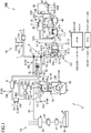
- FIG. 1 is a schematic structural view of such an engine system to which an exhaust gas purification controller for an engine according to an embodiment of the present invention has been applied.
- the engine system 200 mainly includes: an engine E as a diesel engine; an intake system IN configured to provide an intake to the engine E; a fuel supply system FS configured to supply fuel to the engine E; an exhaust gas system EX configured to discharge an exhaust gas of the engine E, sensors 100 to 119 configured to detect various conditions relating to the engine system 200; a PCM (Power-train control Module) 60 configured to control the engine system 200; and a DCU (Dosing control Unit) 70 configured to perform a control relating to an SCR catalyst.
- an engine E as a diesel engine
- an intake system IN configured to provide an intake to the engine E
- a fuel supply system FS configured to supply fuel to the engine E
- an exhaust gas system EX configured to discharge an exhaust gas of the engine E, sensors 100 to 119 configured to detect various conditions relating to the engine system 200
- a PCM (Power-train control Module) 60 configured to control the engine system 200
- a DCU (Dosing control Unit) 70 configured to perform a control relating to an SCR
- the intake system IN has an intake passage 1, through which an intake air passes.
- an air cleaner 3 configured to purify the air introduced from the outside
- a compressor of a turbocharger 5 configured to compress the intake air passing therethrough to raise an intake air pressure
- an intercooler 8 configured to cool the intake air by an outside air or a cooling water
- an intake shutter valve 7 (which corresponds to a throttle valve) configured to adjust a flow amount of the intake air passing therethrough
- a surge tank 12 configured to temporarily store the intake air to be supplied to the engine E.
- an air flow sensor 101 configured to detect an amount of intake air and a temperature sensor 102 configured to detect an intake air temperature.
- a pressure sensor 103 configured to detect the intake air pressure is provided on the turbocharger 5.
- Another temperature sensor 106 configured to detect the intake air temperature is provided on the intake passage 1 just downstream the intercooler 8.
- a position sensor 105 configured to detect an open degree of the intake shutter valve 7 is provided on the intake shutter valve 7.
- a pressure sensor 108 configured to detect the intake air pressure at an intake manifold is provided on the surge tank 12.
- the engine E includes: an intake valve 15 configured to introduce the intake air supplied from the intake passage 1 (more specifically, the intake manifold) into a combustion chamber 17; a fuel injection valve 20 configured to inject fuel toward the combustion chamber 17; a glow plug 21 having a heat generating part located in the combustion chamber 17 and configured to generate heat by applying an electric current; a piston 23 configured to reciprocate by combustion of an air-fuel mixture in the combustion chamber 17; a crankshaft 25 configured to be rotated by a reciprocation of the piston 23; and an exhaust valve 27 configured to discharge an exhaust gas generated by the combustion of the air-fuel mixture in the combustion chamber 17 to an exhaust passage 41.
- the engine E is provided with a crank-angle sensor 100 configured to detect a crank angle as a rotational angle compared with a top dead point or the like of the crank shaft 25.
- the crank-angle sensor 100 is configured to output a detection signal S100 corresponding to the detected crank angle to the PCM 60.
- the PCM 60 is configured to obtain an engine rotation speed based on the detection signal S100.
- the fuel supply system FS has: a fuel tank 30 configured to store the fuel; and a fuel supply passage 38 configured to supply the fuel from the fuel tank 30 to the fuel injection valve 20.
- the fuel supply passage 38 includes, in the following order from its upstream side, a low-pressure fuel pump 31, a high-pressure fuel pump 33, and a common rail 35.
- the exhaust gas system EX has the exhaust passage 41, through which the exhaust gas passes.
- a turbine of the turbocharger 5 configured to be rotated by the exhaust gas and to drive the compressor by its rotation as described above.
- an NO x catalyst 45 configured to purify NO x (Raw NO x ) in the exhaust gas
- a diesel particulate filter (DPF: Diesel Particulate Filter) 46 configured to collect particulate matters (PM: Particulate Matter) in the exhaust gas
- an urea injector 51 configured to inject urea (typically, urea aqueous) toward an inside of the exhaust passage 41 on a side downstream of the DPF 46.
- the NO x catalyst 45 tends to occlude NO x in the exhaust gas in a lean state wherein an air-fuel ratio of the flowing-in exhaust gas is larger than a stoichiometric air-fuel ratio ( ⁇ > 1), and tends to reduce the occluded NO x in another state wherein the air-fuel ratio of the flowing-in exhaust gas is in a vicinity of the stoichiometric air-fuel ratio ( ⁇ ⁇ 1) or in a rich state wherein the air-fuel ratio of the exhaust gas is smaller than the stoichiometric air-fuel ratio ( ⁇ ⁇ 1), so that the NO x catalyst 45 is called an NO x storage (occlusion) reduction type of catalyst (NSC: NO x Storage Catalyst).
- NSC NO x storage (occlusion) reduction type of catalyst
- the NO x catalyst 45 generates and releases NH 3 (ammonia) when the NO x catalyst 45 reduces NO x that has been occluded therein. Specifically, when the NO x is reduced, "N" in the NO x that has been occluded in the NO x catalyst 45 and “H” in “HC” such as unburned fuel supplied toward the NO x catalyst 45 as a reducing agent, or "H” in “H 2 O” generated by in-cylinder combustion, are united to generate NH 3 (ammonia). Further details of these reactions are explained in paragraph 0142.
- the occluded NO x is reduced and purified (by an NO x catalyst regenerator) by controlling the fuel injection valve 20 in the engine E to bring the air-fuel ratio of the flowing-in exhaust gas into a rich state when an amount of the NO x occluded in the NO x catalyst 45 (hereinafter, referred as an NO x occlusion amount) becomes equal to or larger than a predetermined threshold.
- the PCM 60 serves as the NO x catalyst regenerator (has a function as the NO x catalyst regenerator).
- An amount of NO x in the exhaust gas may be estimated based on a driving state of the engine E, a flow amount (flow rate) of the exhaust gas, a temperature of the exhaust gas, and the like.
- the NO x occlusion amount in the NO x catalyst 45 may be estimated by adding up the amount of NO x in the exhaust gas.
- the NO x occlusion amount in the NO x catalyst 45 may be directly detected by an NO x -occlusion-amount detecting sensor 45n.
- the NO x catalyst 45 of the present embodiment has not only the function as the NSC, but also a function as a diesel oxidation catalyst (DOC: Diesel Oxidation Catalyst) 45a (oxidation catalyst) which uses oxygen in the exhaust gas to oxidize hydro carbon (HC), carbon moNO x ide (CO) or the like into water and carbon dioxide.
- DOC Diesel Oxidation Catalyst
- the NO x catalyst 45 of the present embodiment is made of a surface of a catalyst material layer serving as the diesel oxidation catalyst 45a being coated by another catalyst material serving as the NSC.
- the NO x catalyst 45 forms a composite catalyst including the diesel oxidation catalyst 45a. That is, the NO x catalyst 45 is arranged (formed) by being combined with the diesel oxidation catalyst 45a.
- the reaction heat is transferred to the NO x catalyst 45, so that a temperature of the NO x catalyst 45 is raised.
- a temperature sensor 112 is provided on a side just upstream of the NO x catalyst 45.
- the temperature of the NO x catalyst 45 may be estimated based on a temperature detected by the temperature sensor 112.
- the temperature of the NO x catalyst 45 may be detected by another temperature sensor 113 located between the NO x catalyst 45 and the DPF 46.
- the NO x catalyst 45 may be provided directly with an NO x -catalyst-temperature detecting sensor 45t configured to detect a temperature of the NO x catalyst 45.
- the flow amount of the exhaust gas flowing into the NO x catalyst 45 is estimated based on the driving state of the engine, more specifically an engine rotation speed and an engine load.
- an exhaust-gas flow amount detecting sensor 45f configured to detect the flow amount of the exhaust gas flowing into the NO x catalyst 45 may be provided.
- an SCR (Selective Catalytic Reduction) catalyst 47 configured to react (reduce) the NO x in the exhaust gas with the NH 3 generated in the NO x catalyst 45 to purify the NO x .
- the SCR catalyst 47 has also a function of hydrolyzing the urea injected from the urea injector 51 to generate NH 3 (ammonia) (CO(N H 2 ) 2 + H 2 O ⁇ CO 2 + 2NH 3 ), and to react (reduce) the NO x in the exhaust gas with the NH 3 to purify the NO x .
- the urea injector 51 is configured to be controlled by a control signal S51 supplied from the DCU 70 to inject the urea toward the inside of the exhaust passage 41.
- the SCR catalyst 47 is configured to absorb the NH 3 (ammonia) generated by the purification (reduction) of NO x in the NO x catalyst 45 and/or the HN3 generated from the urea injected from the urea injector 51 (cause the NH 3 (ammonia) generated by the purification (reduction) of NO x in the NO x catalyst 45 and/or the HN3 generated from the urea injected from the urea injector 51 to stick to the SCR catalyst 47 itself), and to react the NO x in the exhaust gas with the absorbed (having-stuck) NH 3 to purify (reduce) the NO x .
- the SCR catalyst 47 may be made of a catalyst metal having a function of reducing the NO x with the NH 3 (ammonia), which may be supported by zeolite having a function of trapping the NH 3 to be a catalyst component, which may be further supported by a cell wall as a honeycomb carrier.
- Fe, Ti, Ce, W or the like may be used as the catalyst metal for the NO x reduction.
- a slip catalyst 48 configured to oxidize and purify NH 3 (ammonia) ejected from the SCR catalyst 47.
- an SCR-catalyst-temperature detecting sensor 47t configured to detect a temperature of the SCR catalyst 47.
- the SCR-catalyst-temperature detecting sensor 47t is a sensor configured to directly detect a temperature of the SCR catalyst 47.
- an estimator configured to estimate the temperature of the SCR catalyst from the parameter. For example, a temperature of the SCR catalyst 47 may be estimated based on a temperature detected by a temperature sensor 117 on a side just upstream of the SCR catalyst 47.
- the urea injector 51 serves as an NH 3 supplier configured to supply urea, which is a raw material for NH 3 , to the SCR catalyst 47 and to cause the SCR catalyst 47 to absorb the urea (to cause the urea to stick to the SCT catalyst 47).
- urea which is a raw material for NH 3
- the urea injector 51 is connected to a urea supply passage 53, and the urea supply passage 53 is connected to a urea tank 55 through a urea delivery pump 54.
- the urea supply passage 53 is formed by a pipe capable of delivering the urea (urea aqueous). On the urea supply passage 53, there is arranged a urea-supply-passage pressure sensor 56 configured to measure a change of a pressure thereon when the urea passes therethrough. In addition, on the urea supply passage 53, there is arranged a urea-passage heater 57 for preventing the urea from freezing thereon.
- the urea delivery pump 54 is configured to receive control commands from the DCU 70 and deliver the urea from the urea tank 55 toward the urea injector 51.
- the DCU 70 serves as an NH 3 supply amount controller configured to control a supply amount of the urea (raw material for NH 3 ) to the SCR catalyst 47 by the urea injector 51 (NH 3 supplier).
- the DCU 70 controls an amount of the urea injected from the urea injector 51 to cause the SCR catalyst 47 to absorb a suitable amount of NH 3 , in order to achieve both secure NO x purification performance by the SCR catalyst 47 and inhibition of ejection (slip) of the NH 3 (ammonia) from the SCR catalyst 47.
- the DCU 70 is electrically connected to the urea-supply-passage pressure sensor 56, a urea level sensor 58 and a urea temperature sensor 59.
- the urea-supply-passage pressure sensor 56, the urea level sensor 58 and the urea temperature sensor 59 are respectively configured to output detection signals S52 to S54 corresponding to their detected parameters to the DCU 70.
- the DCU 70 is electrically connected to the urea-passage heater 57, the urea delivery pump 54 and a urea-tank heater 61. Operational states of the urea-passage heater 57, the urea delivery pump 54 and the urea-tank heater 61 can be respectively controlled by control signals S55 to S57 supplied from the DCU 70.
- the DCU 70 consists of a computer including: a CPU, various types of programs configured to be interpreted and executed by the CPU (including a basic control program such as an OS, and an application program to be executed on such an OS for achieving a specific function), and an inside memory such as ROM and/or RAM for storing such programs and/or various data.
- the DCU 70 is two-way communicably connected to the PCM 60, and is configured to receive control commands of the PCM 60 and be controlled thereby. For example, a control signal for supplying various information obtained by the DCU 70 to the PCM 60 is depicted as a control signal S58.
- a pressure sensor 109 configured to detect a pressure of the exhaust gas and a temperature sensor 110 configured to detect a temperature of the exhaust gas.
- a temperature sensor 110 configured to detect a temperature of the exhaust gas.
- an 02 sensor 111 configured to detect oxygen density.
- a temperature sensor 112 configured to detect a temperature of the exhaust gas just upstream the NO x catalyst 45; a temperature sensor 113 configured to detect a temperature of the exhaust gas between the NO x catalyst 45 and the DFP 46; a differential-pressure sensor 114 configured to detect a differential pressure of the exhaust gas between on a side just upstream of the DPF 46 and on an side just downstream of the DPF 46; a temperature sensor 115 configured to detect a temperature of the exhaust gas just downstream the DPF 46; an NO x sensor 116 configured to detect NO x density in the exhaust gas just downstream the DPF 46; a temperature sensor 117 configured to detect a temperature of the exhaust gas just upstream the SCR catalyst 47; an NO x sensor 118 configured to detect NO x density in the exhaust gas just downstream the SCR catalyst 47; and a PM sensor 119 configured to detect PM in the exhaust gas just upstream the slip catalyst 48.
- These sensors 109 to 119 are respectively configured to output detection signals S109
- the turbocharger 5 serves as two-stage supercharging system capable of achieving efficiently high supercharging in the whole range from a low rotation speed range (in which exhaust energy is low) to a high rotation speed range. That is, the turbocharger 5 has: a large-sized turbocharger 5a configured to supercharge a large amount of air in a high rotation speed range; a small-sized turbocharger 5b capable of efficiently supercharging even with low exhaust energy; a compressor bypass valve 5c configured to control a flow of the intake air to a compressor of the small-sized turbocharger 5b; a regulator valve 5d configured to control a flow of the exhaust gas to a turbine of the small-sized turbocharger 5b; and a waste gate valve 5e configured to control a flow of the exhaust gas to a turbine of the large-sized turbocharger 5a. These valves are respectively driven based on the running state of the engine E (the engine rotation speed and the engine load), so that the supercharging by the large-sized turbo
- the engine system 200 of the present embodiment further includes an EGR system 43.
- the EGR system 43 has: an EGR passage 43a connecting the exhaust passage 41 on a side upstream of the turbine of the turbocharger 5 and the intake passage 1 on a side downstream of the compressor of the turbocharger 5 (more specifically, on a side downstream of the intercooler 8); an EGR cooler 43b configured to cool the exhaust gas passing through the EGR passage 43a; a first EGR valve 43c configured to adjust a flow amount of the exhaust gas passing through the EGR passage 43a; an EGR-cooler bypass passage 43d configured to bypass the EGR cooler 43b and cause the exhaust gas to flow therethrough; and a second EGR valve 43e configured to adjust a flow amount of the exhaust gas passing through the EGR-cooler bypass passage 43d.
- FIG. 2 is a block diagram showing an electric structure of the exhaust gas purification controller for the engine according to the present embodiment.
- the PCM 60 of the present embodiment is configured to output a control signal S20 to control the fuel injector valve 20 and a control signal S7 to control the intake shutter valve 7, based on a detection signal S150 outputted from an accelerator open-degree sensor 150 configured to detect an open degree of an accelerator pedal (accelerator open degree) and a detection signal S151 outputted from a vehicle speed sensor 151 configured to detect a vehicle speed, in addition to the detection signals S100 to S119 of the above various sensors 100 to 119.
- the PCM 60 is configured to two-way communicate with the DCU 70 and to output a control signal S8 for causing the DCU 70 to perform such a control that a desired amount of urea is supplied from the urea injector 51.
- the PCM 60 of the present embodiment is configured to control the fuel injection valve 20 in the engine E to bring the air-fuel ratio of the exhaust gas flowing into the NO x catalyst 45 into a rich state (the PCM 60 is configured to serve as an NO x catalyst regenerator) when an amount of NO x occluded in the NO x catalyst 45 becomes equal to or larger than a predetermined threshold.
- the PCM 60 of the present embodiment is configured to perform a "post injection" from the fuel injection valve 20 in order to bring the air-fuel ratio of the exhaust gas into a target air-fuel ratio (specifically, a predetermined air-fuel ratio in a vicinity of a stoichiometric air-fuel ratio or smaller than a stoichiometric air-fuel ratio).
- a target air-fuel ratio specifically, a predetermined air-fuel ratio in a vicinity of a stoichiometric air-fuel ratio or smaller than a stoichiometric air-fuel ratio.
- the PCM 60 of the present embodiment is configured to perform a main injection in which the fuel is injected into a cylinder to output an engine torque based on a driver's operation of the accelerator pedal (basically, in the main injection, an injection amount of the fuel or the like is determined such that the air-fuel ratio of the exhaust gas is in a lean state), and to perform a post injection at a timing not contributing to the output of the engine torque (specifically, at an expansion stroke) after the main injection in order to bring the air-fuel ratio of the exhaust gas into a state wherein the air-fuel ratio of the flowing-in exhaust gas is in a vicinity of the stoichiometric air-fuel ratio ( ⁇ ⁇ 1) or into a rich state wherein the air-fuel ratio of the exhaust gas is smaller than the stoichiometric air-fuel ratio ( ⁇ ⁇ 1), so as to reduce the NO x that has been occluded in the NO x catalyst 45.
- a control for reducing the NO x is a main injection in which the fuel
- the PCM 60 consists of a computer including: a CPU, various types of programs configured to be interpreted and executed by the CPU (including a basic control program such as an OS, and an application program to be executed on such an OS for achieving a specific function), and an inside memory such as ROM and/or RAM for storing such programs and/or various data.
- a basic control program such as an OS
- an application program to be executed on such an OS for achieving a specific function
- an inside memory such as ROM and/or RAM for storing such programs and/or various data.
- the flow of the fuel injection control is started when an ignition switch of the vehicle is turned on to power the PCM 60, and is repeatedly performed in a predetermined cycle.
- the PCM 60 obtains a driving state of the vehicle. Specifically, the PCM 60 obtains at least the accelerator open degree detected by the accelerator open-degree sensor 150, the vehicle speed detected by the vehicle speed sensor 151, the crank angle detected by the crank-angle sensor 100, and a current gear position that has been set at a transmission of the vehicle.
- the PCM 60 sets a target acceleration based on the obtained driving state of the vehicle. Specifically, the PCM 60 selects an acceleration performance map corresponding to the current vehicle speed and the current gear position among a plurality of acceleration performance maps defined for various vehicle speeds and various gear positions (made in advance and stored in a memory or the like), and determines a target acceleration corresponding to the current accelerator open degree with reference to the selected acceleration performance map.
- the PCM 60 determines a target torque of the engine E for achieving the target acceleration.
- the PCM 60 determines the target torque within a torque range that the engine E can output, based on the current vehicle speed, the current gear position, the current road gradient, the current road surface ⁇ , or the like.
- the PCM 60 determines a fuel injection amount to be injected from the fuel injector valve 20, based on the target torque and the current engine rotation speed.
- the fuel injection amount is a fuel injection amount applied in the main injection (main injection amount).
- the PCM 60 sets a fuel injection pattern based on the driving state of the engine E. Specifically, the PCM 60 sets a fuel injection pattern applied in the post injection for a case wherein the DeNO x control is performed.
- the PCM 60 determines a fuel injection amount applied in the post injection (post injection amount) and/or a timing at which the post injection is performed (post injection timing). The details are explained in the following item ⁇ DeNO x Control>.
- the PCM 60 controls the fuel injection valve 20 based on the calculated main injection amount and the set fuel injection pattern (including the post injection amount and the post injection timing when the post injection is performed). That is, the PCM 60 controls the fuel injection valve 20 such that a desired amount of fuel is injected according to a desired fuel injection pattern.
- the PCM 60 of the present embodiment is configured to perform a DeNO x control in which the fuel injection valve 20 executes a post injection so that the air-fuel ratio of the exhaust gas is continuously set to a target air-fuel ratio, which is in a vicinity of the stoichiometric air-fuel ratio or smaller than the stoichiometric air-fuel ratio, in order to lower the amount of the NO x occluded in the NO x catalyst 45 to almost zero, when the amount of the NO x occluded in the NO x catalyst 45 is larger than a predetermined amount, typically when the amount of the occluded NO x is in a vicinity of a limit value (hereinafter, called "active DeNO x control").
- active DeNO x control typically when the amount of the occluded NO x is in a vicinity of a limit value
- the PCM 60 of the present embodiment is configured to perform another DeNO x control in which the fuel injection valve 20 executes a post injection so that the air-fuel ratio of the exhaust gas is temporarily set to a target air-fuel ratio, in order to reduce the NO x occluded in the NO x catalyst 45, when the vehicle is accelerated and the air-fuel ratio of the exhaust gas is changed into a rich side, even when the amount of the NO x occluded in the NO x catalyst 45 is not larger than the predetermined amount (hereinafter, called "passive DeNO x control").
- the post injection is executed so that the air-fuel ratio of the exhaust gas is set to a target air-fuel ratio which is in a vicinity of the stoichiometric air-fuel ratio or smaller than the stoichiometric air-fuel ratio.
- the post injection amount required for setting the air-fuel ratio to the target air-fuel ratio is smaller.
- the passive DeNO x control is performed during each acceleration, so that it is expected that the passive DeNO x control is performed relatively often.
- the DeNO x control can be performed with a high frequency while preventing deterioration of fuel efficiency, which might be caused by any other DeNO x control. It takes only a relatively short time to perform each passive DeNO x control.
- the passive DeNO x control is performed with a high frequency, the amount of the NO x occluded in the NO x catalyst 45 can be efficiently lowered. As a result, the amount of the NO x occluded in the NO x catalyst 45 is not likely to be larger than the predetermined amount, so that performance frequency of the active DeNO x control, which requires a post injection amount larger than that for the passive DeNO x control, can be lowered. This makes it possible to effectively improve the deterioration of fuel efficiency.
- the PCM 60 of the present embodiment sets the air-fuel ratio of the exhaust gas to a target air-fuel ratio, by burning the post-injected fuel in a cylinder of the engine E, when the above active DeNO x control is performed.
- the PCM 60 performs the post injection at a timing when the post-injected fuel is burned in the cylinder.
- the PCM 60 sets a predetermined timing within a former half of the expansion stroke of the engine E as a timing for the post injection in the active DeNO x control.
- the injection timing is for example ATDC45°CA. Since such a timing for the post injection is applied for the active DeNO x control, it is prevented that the post-injected fuel is discharged as unburned fuel (that is, HC) and/or that the post-injected fuel dilutes oil.
- the PCM 60 of the present embodiment sets the air-fuel ratio of the exhaust gas to a target air-fuel ratio, by discharging the post-injected fuel to the exhaust passage 41 as unburned fuel without burning in the cylinder of the engine E, when the above passive DeNO x control is performed.
- the PCM 60 performs the post injection at a timing when the post-injected fuel is not burned in the cylinder but discharged to the exhaust passage 41 as unburned fuel.
- the PCM 60 sets a predetermined timing within a latter half of the expansion stroke of the engine E as a timing for the post injection in the passive DeNO x control.
- the injection timing is for example ATDC110°CA.
- the timing for the post injection in the passive DeNO x control is set on a lag side with respect to the timing for the post injection in the active DeNO x control. Since such a timing for the post injection is applied for the passive DeNO x control, it is prevented that the post-injected fuel is burned in the cylinder to generate smoke (soot).
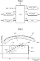
- Fig. 3 explained are driving ranges of the engine E in which the passive DeNO x control and the active DeNO x control are respectively performed.
- the engine rotational speed is shown along the horizontal axis
- the engine load is shown along the vertical axis.
- the curve line L1 shows a maximum torque line of the engine E.
- the PCM 60 of the present embodiment performs the active DeNO x control when the engine load is within a middle load range which is greater than a first predetermined load Lo1 and smaller than a second predetermined load Lo2 (> the first predetermined load Lo1) and when the engine rotation speed is within a middle rotation speed range greater than a first predetermined rotation speed N1 and smaller than a second rotation speed N2 (> the first predetermined rotation speed N1), i.e., when the engine load and the engine rotation speed are included in a driving range shown by the sign R12 (hereinafter, called "active DeNO x performing range R12").
- the reasons why such an active DeNO x performing range R12 is adopted are as follows.
- the post injection is executed at a timing at which the post-injected fuel is burned in the cylinder in view of inhibiting generation of HC, which might be caused by the post-injected fuel being discharged as it is, and also inhibiting oil dilution, which might be caused by the post-injected fuel.
- generation of smoke is inhibited
- generation of HC that is, discharging unburned fuel that might be caused by incomplete combustion
- a time period until the post-injected fuel is burned is secured as long as possible, so that ignition happens in a state the air and the fuel are suitably mixed. This inhibits the generation of smoke and HC.
- a suitable amount of EGR gas is introduced, which effectively lags the ignition of the post-injected fuel.
- the reasons why the generation of HC is to be inhibited in the active DeNO x control are to prevent the gas passage from clogging by the soot bonded with the HC which serves as a binder, when the EGR gas is introduced as described above and the HC is circulated into the intake system IN as (a part of) the EGR gas.
- the reasons are to prevent the HC from being discharged without being purified, when the active DeNO x control is performed in a driving region wherein the temperature of the NO x catalyst 45 is so low that purification performance of HC (purification performance of HC by the DOC 45a in the NO x catalyst 45) is not assured.
- the active DeNO x performing range R12 may include such an area wherein the temperature of the NO x catalyst 45 is so low that purification performance of HC is not assured.
- the reasons why the generation of smoke is to be inhibited in the active DeNO x control are to inhibit deterioration of the fuel efficiency, which might be caused if DPF regeneration (which controls a post injection similarly to the DeNO x control) for burning and removing the PM collected by the DPF 46 is performed with a high frequency, although the PM corresponding to the smoke is collected by the DPF 46.
- the driving range of the engine E corresponding to the middle load range and the middle rotation speed range is adopted as the active DeNO x performing range R12 for performing an active DeNO x control.
- an active DeNO x control is performed only in the active DeNO x performing range R12.
- An active DeNO x control is forbidden in a driving range out of the active DeNO x performing range R12.
- the purification performance of the NO x by the SCR catalyst 47 is sufficiently assured.
- the NO x is purified by the SCR catalyst 47, which can prevent the NO x from being discharged from the vehicle without performing the DeNO x control.
- the amount of the exhaust gas is so larger that the NO x is not fully purified by the SCR catalyst 47, and thus the passive DeNO x control is performed.
- the passive DeNO x control as described above, the post injection is performed at a timing when the post-injected fuel is not burned in the cylinder but discharged to the exhaust passage 41 as unburned fuel.
- the temperature of the NO x catalyst 45 is so high that the purification performance of the HC (purification performance of the HC by the DOC 45a in the NO x catalyst 45) is secured.
- the so discharged unburned fuel can be securely purified by the NO x catalyst 45.
- the passive DeNO x control if the post-injected fuel is burned in the cylinder in the same way as in the active DeNO x control, the smoke may be generated. The reasons are the same as those why the active DeNO x control is forbidden when the engine load is high.
- the PCM 60 resumes the active DeNO x control. Accordingly, the active DeNO x control is not finished until the amount of the NO x that has been occluded in the NO x catalyst 45 is lowered to almost zero.
- the NO x catalyst 45 exerts the purification performance of the NO x in a relatively low temperature range (in a range shown by the sign R24), and the SCR catalyst 47 exerts the purification performance of the NO x in a higher temperature range (in a range shown by the sign R25) compared with the temperature range in which the NO x catalyst 45 exerts the purification performance of the NO x .
- a temperature in a vicinity of the lower border of the temperature range in which an NO x purification rate equal to or larger than a predetermined value can be obtained by the SCR catalyst 47 is used as a judgement temperature (hereinafter, called "SCR judgment temperature").
- post injection amount for DeNO x I a calculation flow of the post injection amount to be applied in the DeNO x control (hereinafter, called "post injection amount for DeNO x I) in the present embodiment.
- the calculation flow of the post injection amount for DeNO x is repeatedly performed in a predetermined cycle, in parallel to the above flow of the fuel injection control. That is, the post injection amount for DeNO x I is calculated at any time while the fuel injection control is performed.
- the PCM 60 obtains the driving state of the engine E. Specifically, the PCM 60 obtains at least an amount of the intake air detected by the air flow sensor 101, oxygen density detected by the O2 sensor 111 and a main injection amount calculated by the flow of the fuel injection control. In addition, the PCM 60 obtains an amount of the exhaust gas circulated into the intake system IN by the EGR system 43 (an amount of the EGR gas), which is obtained by a predetermined model or the like. Furthermore, the PCM 60 obtains an NH 3 absorption amount that is an amount of the NH 3 absorbed in (sticking to) the SCR catalyst 47.
- the NH 3 absorption amount an estimated value of an amount of the NH 3 is used, which is estimated at any time based on: a urea injection amount injected from the urea injection valve; a generation amount of the NH 3 generated in the DeNO x control; and an estimated value of an amount of the NO x supplied to the SCR catalyst estimated based on the driving state of the engine and the purification efficiency of the NO x catalyst.
- the NH 3 absorption amount may be obtained by another method.
- the SCR catalyst 47 may be provided with an NH 3 -absorption-amount detecting sensor 47n configured to detect an NH 3 absorption amount.
- the PCM 60 sets a target air-fuel ratio to be applied for reducing the NO x that has been occluded in the NO x catalyst 45, based on the estimated NH 3 absorption amount of the SCR catalyst 47. Specifically, the PCM 60 sets a target air-fuel ratio to be applied for performing an active DeNO x control and a target air-fuel ratio to be applied for performing a passive DeNO x control, respectively, based on the NH 3 absorption amount of the SCR catalyst 47.
- the setting method of the target air-fuel ratio(s) is explained later with reference to Fig. 5 .
- the PCM 60 calculates a post injection amount (post injection amount for DeNO x ) required to achieve the set target air-fuel ratio. That is, the PCM 60 determines how much the post injection amount should be applied in addition to the main injection amount in order to bring the air-fuel ratio of the exhaust gas into the target air-fuel ratio. In this case, the PCM 60 calculates a post injection amount for achieving a set target air-fuel ratio for performing an active DeNO x control and a post injection amount for achieving a set target air-fuel ratio for performing a passive DeNO x control, respectively.
- Fig. 5 is an explanatory view of a setting method of a target air-fuel ratio according to the present embodiment.
- the NH 3 absorption amount of the SCR catalyst 47 is shown along the horizontal axis
- the target air-fuel ratio is shown along the vertical axis.
- ⁇ 1 represents a stoichiometric air-fuel ratio.
- An air-fuel ratio range R21 on a rich side of the stoichiometric air-fuel ratio ⁇ 1 represents a range in which the NO x occluded in the NO x catalyst 45 can be reduced
- another air-fuel ratio range R22 on a lean side of the stoichiometric air-fuel ratio ⁇ 1 represents a range in which the NO x occluded in the NO x catalyst 45 cannot be reduced.
- an air-fuel ratio range R23 on a rich side of a limit air-fuel ratio ⁇ 2 unburned fuel may be supplied to the EGR system 43, which may result in deterioration of reliability of the EGR system 43.
- a graph G11 shows a target air-fuel ratio to be set based on an NH 3 absorption amount of the NH 3 absorbed (stuck) in the SCR catalyst 47, when a passive DeNO x control is performed.
- a graph G12 shows a target air-fuel ratio to be set based on an NH 3 absorption amount of the NH 3 absorbed (stuck) in the SCR catalyst 47, when an active DeNO x control is performed.
- the target air-fuel ratio is set in a vicinity of the limit air-fuel ratio ⁇ 2, in order to increase the total amount of the "H" components in the exhaust gas and thus increase the NH 3 generation amount of the NH 3 generated from the SCR catalyst 47.
- the target air-fuel ratio is set at a ratio relatively closer to the stoichiometric air-fuel ratio ⁇ 1, dependently on the NH 3 absorption amount in the SCR catalyst 47.
- a flow of setting an active DeNO x control performing flag is repeatedly performed in a predetermined cycle by the PCM 60 or the like, in parallel to the above flow of the fuel injection control or the like.
- the PCM obtains various information of the vehicle. Specifically, the PCM 60 obtains at least a temperature of the NO x catalyst 45, a temperature of the SCR catalyst 47, and an NO x occlusion amount of the NO x catalyst 45. In this case, the temperature of the NO x catalyst 45 is estimated based on the temperature detected by the temperature sensor 112 located on the side just upstream of the NO x catalyst 45. The temperature of the SCR catalyst 47 is estimated based on the temperature detected by the temperature sensor 117 located on the side just upstream of the SCR catalyst 47.
- an amount of NO x in the exhaust gas is estimated based on the driving state of the engine E, the flow amount of the exhaust gas, the temperature of the exhaust gas and the like, and then the NO x occlusion amount is estimated by adding up the amount of NO x in the exhaust gas.
- the PCM 60 judges whether the obtained SCR temperature is smaller than the SCR judgment temperature (for example, 300 °C). When the judgment result is NO, the PCM 60 judges whether the flow amount of the exhaust gas is smaller than a predetermined value.
- the PCM 60 judges whether a predetermined time period has passed after a start of the engine E. When the judgment result is YES, the PCM 60 sets "1" as the active DeNO x control performing flag, in order to allow a performance of the active DeNO x control. When the predetermined time period has not passed after the start of the engine E, the PCM 60 judges whether the NO x occlusion amount is not smaller than a first threshold (for example, 4 g). When the NO x occlusion amount is equal to or larger than the first threshold, the PCM 60 sets "1" as the active DeNO x control performing flag, in order to allow a performance of the active DeNO x control. Then, the process is completed.
- a first threshold for example, 4 g
- the PCM 60 sets "0" as the active DeNO x control performing flag, in order to forbid a performance of the active DeNO x control. Then, the process is completed.
- a flow of setting a passive DeNO x control performing flag is also repeatedly performed in a predetermined cycle by the PCM 60 or the like, in parallel to the above flow of the fuel injection control, the above flow of setting the active DeNO x control performing flag, or the like.
- the PCM obtains various information of the vehicle. Specifically, the PCM 60 obtains at least a temperature of the NO x catalyst 45, a temperature of the SCR catalyst 47, a target torque determined by the above flow of the fuel injection control, a post injection amount for DeNO x calculated by the above calculation flow of the post injection amount for DeNO x (specifically, a post injection amount for DeNO x calculated to be applied in a passive DeNO x control), and an NO x occlusion amount of the NO x catalyst 45.
- the way how to obtain (determine) the temperature of the NO x catalyst 45, the temperature of the SCR catalyst 47 and the NO x occlusion amount is the same as described for the active DeNO x control.
- the PCM 60 judges whether the obtained SCR temperature is smaller than the SCR judgment temperature (for example, 300 °C). When the judgment result is NO, the PCM 60 judges whether the flow amount of the exhaust gas is smaller than a predetermined value.
- the PCM 60 judges whether the NO x occlusion amount is not smaller than a second threshold (for example, 2 g). When the NO x occlusion amount is equal to or larger than the second threshold, the PCM 60 sets "1" as the passive DeNO x control performing flag, in order to allow a performance of the passive DeNO x control. Then, the process is completed.
- a second threshold for example, 2 g
- the PCM 60 sets "0" as the passive DeNO x control performing flag, in order to forbid a performance of the passive DeNO x control. Then, the process is completed.
- FIG. 6A is a flowchart showing an active DeNO x control according to the present embodiment (active DeNO x control flow).
- This active DeNO x control flow is repeatedly performed in a predetermined cycle by the PCM 60 or the like, in parallel to the above flow of the fuel injection control, the above flow of setting the active DeNO x control performing flag, or the like.
- the PCM obtains various information of the vehicle. Specifically, the PCM 60 obtains at least a load of the engine, a rotation speed of the engine, a temperature of the NO x catalyst 45, a post injection amount for DeNO x calculated by the above calculation flow of the post injection amount for DeNO x (specifically, a post injection amount for DeNO x calculated to be applied in an active DeNO x control), and a value of the active DeNO x control performing flag set by the above flow of setting the active DeNO x control performing flag.
- the PCM 60 judges whether the active DeNO x control performing flag obtained at the step S401 is "1" or not. That is, the PCM 60 judges whether the active DeNO x control should be performed or not.
- the active DeNO x control performing flag is "1" (a step S402: Yes)
- the process proceeds to a step S403.
- the active DeNO x control performing flag is "0" (a step S402: No)
- the process proceeds to Fig. 6B .
- the PCM 60 judges whether the driving state of the engine (the load of the engine and the rotation speed of the engine) is included in the active DeNO x performing area R12 (see Fig. 3 ) or not.
- the process proceeds to a step S405.
- the driving state of the engine is not included in the active DeNO x performing area R12 (a step S403: No)
- the process proceeds to a step S404.
- the PCM 60 sets a post injection timing (post injection time) to be applied in the active DeNO x control.
- the air-fuel ratio of the exhaust gas is set (adjusted) to the target air-fuel ratio by burning the post-injected fuel in the cylinder.
- the post injection timing is set on a suitably advanced-angle side.
- a suitable timing within a first half of the expansion stroke is adopted as a post injection timing for the active DeNO x control.
- a suitable amount of the EGR gas is introduced during the active DeNO x control. For these reasons, the ignition of the post-injected fuel is lagged, which can inhibit generation of the smoke or the like.
- the PCM 60 performs a normal fuel injection control not including a post injection, without performing an active DeNO x control, that is, without performing a fuel injection control including a post injection in order to set (adjust) the air-fuel ratio of the exhaust gas to the target air-fuel ratio (step S404).
- the PCM 60 performs only a main injection control wherein an amount of fuel dependent on the target torque is main injected.
- the PCM 60 performs the process of the step S404 during the above flow of the fuel injection control. Then, the process goes back to the step S403 to make the above judgment of the step S403 again.
- the PCM 60 performs the normal fuel injection control, and when the driving state of the engine goes into the active DeNO x performing area R12, the PCM 60 switches the normal fuel injection control into the fuel injection control of the active DeNO x control. For example, when the driving state of the engine goes out of the active DeNO x performing area R12 during the fuel injection control of the active DeNO x control, the PCM 60 stops the current fuel injection control and performs the normal fuel injection control. Subsequently, when the driving state of the engine goes into the active DeNO x performing area R12, the fuel injection control of the active DeNO x control is resumed.
- the PCM 60 judges whether the post injection amount for DeNO x control obtained at the step S401 is smaller than a predetermined judgment value for post injection amount.
- step S406 when the post injection amount for DeNO x control is smaller than the predetermined judgment value for post injection amount (step S406: Yes), the process proceeds to a step S407.
- the PCM 60 controls the fuel injection valve 20 in order to perform a post injection of the post injection amount for DeNO x obtained by the step S401.
- the PCM 60 performs the process of the step S407 during the above flow of the fuel injection control. Then, the process proceeds to a step S410.
- step S406 when the post injection amount for DeNO x is not smaller than the judgment value for post injection amount (step S406: Yes), the process proceeds to a step S408.
- the PCM 60 performs a control of lowering oxygen density in the air introduced to the engine E, in order to set (adjust) the air-fuel ratio of the exhaust gas to the target air-fuel ratio by a post injection amount not beyond the judgment value for post injection amount (specifically, the judgment value for post injection amount itself is used as the post injection amount for DeNO x ).
- the PCM 60 performs at least one of: a control of driving the intake shutter valve 7 in a valve-closing direction (this is shown in Fig.
- the PCM 60 determines a supercharging pressure required to adjust the air-fuel ratio of the exhaust gas to the target air-fuel ratio by the post injection amount for DeNO x to which the judgment value for post injection amount has been applied, and controls the intake shutter valve 7 to a desired open degree in the valve-closing direction based on the actual supercharging pressure (the pressure detected by the pressure sensor 108) and the amount of the EGR gas, in order to achieve the required supercharging pressure. Then, the process proceeds to a step S409.
- the intake shutter valve 7 is set to be fully open during a normal driving state of the engine E.
- the intake shutter valve 7 is basically set to be at a base open degree that has been predetermined.
- the intake shutter valve 7 is feedback controlled based on the supercharging pressure.
- the PCM 60 applies the judgment value of post injection amount to the post injection amount for DeNO x , that is, sets the post injection amount for DeNO x using the judgment value of post injection amount, and controls the fuel injection valve 20 in order to perform a post injection according to the currently set post injection amount for DeNO x .
- the PCM 60 performs the process of the step S409 during the above flow of the fuel injection control. Then, the process proceeds to a step S410.
- the NO x catalyst 45 When the active DeNO x control is performed, the NO x catalyst 45 generates the NH 3 when reducing the NO x occluded therein as described above, and discharges the generated NH 3 .
- the PCM 60 judges whether the amount of the NO x that has been occluded in the NO x catalyst 45 is lowered to almost zero.
- the NO x occlusion amount of the NO x catalyst 45 is lowered to almost zero (step S410: Yes)
- the process is finished.
- the PCM 60 finishes the active DeNO x control.
- step S410 Yes
- the process goes back to the step S403.
- the PCM 60 continues the active DeNO x control. That is, the PCM 60 continues the active DeNO x control until the amount of the NO x that has been occluded in the NO x catalyst 45 is lowered to almost zero.
- the DeNO x control is resumed so that the NO x occlusion amount of the NO x catalyst 45 is lowered to almost zero.
- Fig. 6B is a flowchart showing a passive DeNO x control according to the present embodiment (passive DeNO x control flow).
- This passive DeNO x control flow is repeatedly performed in a predetermined cycle by the PCM 60 or the like, in parallel to the above flow of the fuel injection control, the above flow of setting the passive DeNO x control performing flag, or the like.
- the PCM obtains various information of the vehicle. Specifically, the PCM 60 obtains at least a post injection amount for DeNO x calculated by the above calculation flow of the post injection amount for DeNO x (specifically, a post injection amount for DeNO x calculated to be applied in an passive DeNO x control), and a value of the passive DeNO x control performing flag set by the above flow of setting the passive DeNO x control performing flag.
- the PCM 60 judges whether the passive DeNO x control performing flag obtained at the step S501 is "1" or not. That is, the PCM 60 judges whether the passive DeNO x control should be performed or not.
- the passive DeNO x control performing flag is "1" (a step S502: Yes)
- the process proceeds to a step S503.
- the passive DeNO x control performing flag is "0" (a step S502: No)
- the passive DeNO x control is not performed and the process is finished.
- the PCM 60 controls the fuel injection valve 20 in order to perform a post injection of the post injection amount for DeNO x obtained by the step S501. That is, the passive DeNO x control is performed. In fact, the PCM 60 performs the process of the step S503 during the above flow of the fuel injection control. Then, the process proceeds to a step S502.
- the NO x catalyst 45 When the passive DeNO x control is performed, the NO x catalyst 45 generates the NH 3 when reducing the NO x occluded therein as described above, and discharges the generated NH 3 .
- the PCM 60 judges whether the passive DeNO x control performing flag has changed to "0" or not. As a result, if the passive DeNO x control performing flag has changed to "0" (step S504: Yes), the process is finished. In this case, the PCM 60 finishes the passive DeNO x control. On the other hand, if the passive DeNO x control performing flag has not changed to "0" (step S504: No), that is, if the passive DeNO x control performing flag is still maintained “1 ", the process goes back to the step S503. In this case, the PCM 60 continues the passive DeNO x control. That is, the PCM 60 continues the passive DeNO x control until the passive DeNO x control performing flag is switched from "1" to "0".
- the injection control is performed when the purification (reduction) of NO x by the SCR catalyst 47 is performed.
- the engine system 200 of the present embodiment is configured to perform the purification of NO x , (1) mainly only by the SCR catalyst 47, when a flow amount of the exhaust gas detected by the exhaust-gas flow amount detecting sensor 45f is smaller than a predetermined threshold and when a temperature of the SCR catalyst 47 detected by the SCR-catalyst-temperature detecting sensor 47t is smaller than a predetermined threshold (for example, 300 °C); and (2) both by the NO x catalyst 45 and by the SCR catalyst 47, when a flow amount of the exhaust gas detected by the exhaust-gas flow amount detector sensor 45f is equal to or larger than the predetermined threshold.
- a predetermined threshold for example, 300 °C
- the injection control of the urea injector 51 is performed dependently on a difference between the current NH 3 absorption amount of the SCR catalyst 47 and a target NH 3 absorption amount.
- a suitable supply amount of the NH 3 from the NO x catalyst 45 to the SCR catalyst 47 is calculated, and thus a suitable reduction amount of the supply amount of the urea is calculated.
- the DCU 70 has a first reduction amount determiner 71 configured to determine a reduction amount corresponding to a purification process of NO x that has been occluded in the NO x catalyst, and a second reduction amount determiner 72 configured to determine a reduction amount corresponding to a purification process of Raw NO x .
- a reduction amount corresponding to the purification process of NO x that has been occluded in the NO x catalyst 45 and a reduction amount corresponding to the purification process of Raw NO x can be taken into consideration independently of each other.
- the DCU 70 of the present embodiment is configured to reduce and adjust the supply amount of the urea to the SCR catalyst 47, based on the sum of the reduction amount determined by the first reduction amount determiner 71 and the reduction amount determined by the second reduction amount determiner 72.
- the injection amount of the urea injection valve is adjusted sequentially in conjunction with a DeNO x control of the NO x catalyst.
- the injection amount of the urea injection valve is adjusted when the urea injection is started in an NO x purification range by the SCR catalyst.
- the urea injection is limited until the amount of the NH 3 becomes smaller than the target NH 3 absorption amount.
- the urea injection amount is adjusted so that it is reduced by the amount of the NH 3 introduced by the DeNO x control.
- the DCU 70 of the present embodiment is configured to reduce and adjust the supply amount of the urea to the SCR catalyst 47 by the urea injector 51, in a state wherein the air-fuel ratio of the exhaust gas flowing into the NO x catalyst 45 is rich and the NO x occluded in the NO x catalyst 45 is reduced to N 2 .
- a reduction amount of the supply amount of the urea determined by the DCU 70 is set smaller when the temperature of the NO x catalyst 45 detected by the NO x -catalyst-temperature detecting sensor 45t is higher.
- the reduction amount of the supply amount of the urea determined by the DCU 70 is set to vary less greatly as the temperature of the NO x catalyst 45 detected by the NO x -catalyst-temperature detecting sensor 45t varies, when the flow amount of the exhaust gas detected by the exhaust-gas flow amount detecting sensor 45f is larger.
- the DCU 70 has the first reduction amount determiner 71 configured to determine a reduction amount corresponding to a purification process of NO x that has been occluded in the NO x catalyst 45, and the second reduction amount determiner 72 configured to determine a reduction amount corresponding to a purification process of Raw NO x .
- the reduction amount of the supply amount of the urea determined by the first reduction amount determiner 71 is set to vary more greatly, compared with the reduction amount of the supply amount of the urea determined by the second reduction amount determiner 72, as the temperature of the NO x catalyst 45 detected by the NO x -catalyst-temperature detecting sensor 45t varies.
- Each of the reduction amount of the supply amount of the urea determined by the first reduction amount determiner 71 and the reduction amount of the supply amount of the urea determined by the first reduction amount determiner 72 is set to vary less greatly as the temperature of the NO x catalyst 45 detected by the NO x -catalyst-temperature detecting sensor 45t varies, when the flow amount of the exhaust gas detected by the exhaust-gas flow amount detecting sensor 45f is larger.
- the reduction amount of the supply amount of the urea determined by the first reduction amount determiner 71 is set to vary more greatly, compared with the reduction amount of the supply amount of the urea determined by the second reduction amount determiner 72, as the flow amount of the exhaust gas detected by the exhaust-gas flow amount detecting sensor 45f varies.
- the reduction amount of the supply amount of the urea determined by the second reduction amount determiner 72 is set substantially constant no matter how the temperature of the NO x catalyst 45 detected by the NO x -catalyst-temperature detecting sensor 45t varies.
- the DCU 70 of the present embodiment is configured to reduce and adjust the supply amount of the urea to the SCR catalyst 47, based on the sum of the reduction amount of the supply amount of the urea determined by the first reduction amount determiner 71 and the reduction amount of the supply amount of the urea determined by the second reduction amount determiner 72.
- both a reaction generating NH 3 for example, BaNO 3 + CO + H 2 ⁇ NH 3 , NO + CO + H 2 ⁇ NH 3 ) (conceptual formula) and a reaction consuming (decomposing) the NH 3 (BaN03 + NH 3 ⁇ N 2 , NO + NH 3 ⁇ N 2 ) (conceptual formula) occur, but the former reaction is more dominant than the latter one when the temperature of the NO x catalyst 45 is higher.
- a correspondence table (or function) is prepared in advance in which: characteristics as shown in Fig. 8A are reflected, and thus (the air-fuel ratio and) the temperature of the NO x catalyst 45 detected by the NO x -catalyst-temperature detecting sensor 45t and the flow amount of the exhaust gas detected by the exhaust-gas flow amount detecting sensor 45f are input parameters while the reduction amount of the supply amount of the urea is an output parameter. This matches the contents described in the above paragraphs 0134 to 0137.
- the reason therefor is as follows. Since the Raw NO x flows as the exhaust gas, differently from the NO x that has been occluded in the NO x catalyst 45 (which may cause a reaction consuming the NH 3 just after a reaction generating the NH 3 ), a reaction consuming the NH 3 is not likely to occur, even when the temperature of the catalyst 45 is higher.
- a correspondence table (or function) is prepared in advance in which: characteristics as shown in Fig. 8B are reflected, and thus (the air-fuel ratio and) the temperature of the NO x catalyst 45 detected by the NO x -catalyst-temperature detecting sensor 45t and the flow amount of the exhaust gas detected by the exhaust-gas flow amount detecting sensor 45f are input parameters while the reduction amount of the supply amount of the urea is an output parameter which is substantially constant. This matches the contents described in the above paragraphs 0134 to 0137.
- the DCU 70 of the present embodiment is configured to reduce and adjust the supply amount of the urea to the SCR catalyst 47 by the urea injector 51, by mainly considering the flow amount of the exhaust gas, as an alternative to the above ⁇ (1) Control Considering Temperature of NO x catalyst>. Specifically, a reduction amount of the supply amount of the urea determined by the DCU 70 is set larger when the flow amount of the exhaust gas detected by the exhaust-gas flow amount detecting sensor 45f is larger.
- the reduction amount of the supply amount of the urea determined by the DCU 70 is set to vary less greatly, compared with in a range smaller than the first threshold, as the flow amount of the exhaust gas detected by the exhaust-gas flow amount detecting sensor 45f varies.
- the DCU 70 in the present embodiment has the first reduction amount determiner 71 configured to determine a reduction amount corresponding to a purification process of NO x that has been occluded in the NO x catalyst 45, and the second reduction amount determiner 72 configured to determine a reduction amount corresponding to a purification process of Raw NO x .
- the reduction amount of the supply amount of the urea determined by the second reduction amount determiner 72 is set to vary more greatly, compared with the reduction amount of the supply amount of the urea determined by the first reduction amount determiner 71, as the flow amount of the exhaust gas detected by the exhaust-gas flow amount detecting sensor 45f varies.
- the reduction amount of the supply amount of the urea determined by the second reduction amount determiner 72 is set to vary less greatly, compared with the reduction amount of the supply amount of the urea determined by the first reduction amount determiner 71, as the flow amount of the exhaust gas detected by the exhaust-gas flow amount detecting sensor 45f varies.
- the reduction amount of the supply amount of the urea determined by the second reduction amount determiner 72 is set substantially constant no matter how the flow amount of the exhaust gas detected by the exhaust-gas flow amount detecting sensor 45f varies.
- the reduction amount of the supply amount of the urea determined by the second reduction amount determiner 72 is set to vary more greatly as the flow amount of the exhaust gas detected by the exhaust-gas flow amount detecting sensor 45f varies, when the temperature of the NO x catalyst 45 detected by the NO x -catalyst-temperature detecting sensor 45t is higher.
- the DCU 70 of the present embodiment is configured to reduce and adjust the supply amount of the urea to the SCR catalyst 47, based on the sum of the reduction amount of the supply amount of the urea determined by the first reduction amount determiner 71 and the reduction amount of the supply amount of the urea determined by the second reduction amount determiner 72.
- the amount of the generated NH 3 reduces less greatly (the gradient is smaller) as the flow amount of the exhaust gas is increased.
- the predetermined first threshold for example, 25 g/s
- the amount of the generated NH 3 is increased less greatly, compared with in the range smaller than the first threshold, as the flow amount of the exhaust gas is increased.
- a correspondence table (or function) is prepared in advance in which: characteristics as shown in Fig. 9A are reflected, and thus (the air-fuel ratio and) the temperature of the NO x catalyst 45 detected by the NO x -catalyst-temperature detecting sensor 45t and the flow amount of the exhaust gas detected by the exhaust-gas flow amount detecting sensor 45f are input parameters while the reduction amount of the supply amount of the urea is an output parameter.
- the flow amount of the exhaust gas is in the range smaller than the predetermined second threshold (for example, 25 g/s)
- the amount of the generated NH 3 in the purification process of the Raw NO x varies more greatly against the variation of the flow amount of the exhaust gas, compared with the variation of the amount of the generated NH 3 in the purification process of the occluded NO x against the variation of the flow amount of the exhaust gas (see Fig. 9A ).
- the amount of the generated NH 3 in the purification process of the Raw NO x varies less greatly (substantially keeps constant) against the variation of the flow amount of the exhaust gas, compared with the variation of the amount of the generated NH 3 in the purification process of the occluded NO x against the variation of the flow amount of the exhaust gas (see Fig. 9A ).
- a correspondence table (or function) is prepared in advance in which: characteristics as shown in Fig. 9B are reflected, and thus (the air-fuel ratio and) the temperature of the NO x catalyst 45 detected by the NO x -catalyst-temperature detecting sensor 45t and the flow amount of the exhaust gas detected by the exhaust-gas flow amount detecting sensor 45f are input parameters while the reduction amount of the supply amount of the urea is an output parameter. This matches the contents described in the above paragraphs 0148 to 0154.
- the PCM 60 of the present embodiment is configured to reduce and adjust the supply amount of the urea to the SCR catalyst 47 by the urea injector 51, by considering the amount of the reducing agent (HC, CO), in addition to the above ⁇ (1) Control Considering Temperature of NO x catalyst> or the above ⁇ (2) Control Mainly Considering Flow Amount of Exhaust Gas>, or as an alternative to any of them. Specifically, an amount of the reducing agent can be obtained (known) from the target air-fuel ratio set by the PCM 60.
- a reduction amount of the supply amount of the urea determined by the DCU 70 is set larger when the target air-fuel ratio set by the PCM 60 is smaller and thus when the amount of the reducing agent is judged to be larger (in the present embodiment, the PCM 60 serves as a reducing agent amount detector).
- the PCM 60 in the present embodiment has the first reduction amount determiner 71 configured to determine a reduction amount corresponding to a purification process of NO x that has been occluded in the NO x catalyst 45, and the second reduction amount determiner 72 configured to determine a reduction amount corresponding to a purification process of Raw NO x .
- the reduction amount of the supply amount of the urea determined by the first reduction amount determiner 71 is set to vary more greatly, compared with the reduction amount of the supply amount of the urea determined by the second reduction amount determiner 72, as the amount of the reducing agent estimated by the PCM 60 (reducing agent amount detector) varies.
- the reduction amount of the supply amount of the urea determined by the first reduction amount determiner 71 is set larger when the flow amount of the exhaust gas detected by the exhaust-gas flow amount detecting sensor 45f is larger.
- the reduction amount of the supply amount of the urea determined by the second reduction amount determiner 72 is set to vary less greatly, compared with in a range smaller than the threshold, as the estimated amount of the reducing agent varies.
- the reduction amount of the supply amount of the urea determined by the second reduction amount determiner 72 is set substantially constant no matter how the amount of the reducing agent estimated by the PCM 60 (reducing agent amount detector) varies.
- the reduction amount of the supply amount of the urea determined by the first reduction amount determiner 71 is set to vary at a substantially constant gradient as the amount of the reducing agent estimated by the PCM 60 (reducing agent amount detector) varies.
- the reduction amount of the supply amount of the urea determined by the second reduction amount determiner 72 is set to vary more greatly in the range smaller than the above threshold, compared with in the range equal to or larger than the above threshold, as the flow amount of the exhaust gas detected by the exhaust-gas flow amount detecting sensor 45f varies.
- the PCM 60 is configured to reduce and adjust the supply amount of the urea to the SCR catalyst 47, based on the sum of the reduction amount of the supply amount of the urea determined by the first reduction amount determiner 71 and the reduction amount of the supply amount of the urea determined by the second reduction amount determiner 72.
- Fig. 10A shows data for an amount of the NH 3 (ammonia) generated in the purification process of the NO x that has been occluded in the NO x catalyst 45, against variation of the target air-fuel ratio, when the temperature of the NO x catalyst 45 is 250 °C and the flow amount of the exhaust gas is 30 g/s to 50 g/s.
- the amount of the generated NH 3 is increased substantially in inverse proportion to the amount of the reducing agent corresponding to the target air-fuel ratio (substantially in proportion to reduction of the target air-fuel ratio).
- the amount of the generated NH 3 is larger when the flow amount of the exhaust gas is larger.
- a correspondence table (or function) is prepared in advance in which: characteristics as shown in Fig. 10A are reflected, and thus (the temperature of the NO x catalyst 45 detected by the NO x -catalyst-temperature detecting sensor 45t and) the target air-fuel ratio and the flow amount of the exhaust gas detected by the exhaust-gas flow amount detecting sensor 45f are input parameters while the reduction amount of the supply amount of the urea is an output parameter. This matches the contents described in the above paragraphs 0166 to 0172.
- Fig. 10B shows data for an amount of the NH 3 (ammonia) generated in the purification process of the Raw NO x discharged from the engine, against the variation of the target air-fuel ratio, when the temperature of the NO x catalyst 45 is 250 °C and the flow amount of the exhaust gas is 30 g/s to 50 g/s.
- the amount of the generated NH 3 in the purification process of the Raw NO x varies less greatly against the variation of the amount of the reducing agent (the variation of the target air-fuel ratio), compared with the variation of the amount of the generated NH 3 in the purification process of the occluded NO x against the variation of the amount of the reducing agent (see Fig. 10A ).
- the estimated amount of the reducing agent is in the range equal to or larger than the predetermined threshold (for example, a threshold corresponding to an air-fuel ratio of 0.97), the amount of the generated NH 3 varies less greatly (substantially keeps constant), compared with in the range smaller than the threshold, as the estimated amount of the reducing agent varies.
- the predetermined threshold for example, a threshold corresponding to an air-fuel ratio of 0.97
- the amount of the generated NH 3 varies more greatly, compared with in the range equal to or larger than the threshold, as the flow amount of the exhaust gas detected by the exhaust-gas flow amount detecting sensor 45f varies.
- a correspondence table (or function) is prepared in advance in which: characteristics as shown in Fig. 10B are reflected, and thus (the temperature of the NO x catalyst 45 detected by the NO x -catalyst-temperature detecting sensor 45t and) the target air-fuel ratio and the flow amount of the exhaust gas detected by the exhaust-gas flow amount detecting sensor 45f are input parameters while the reduction amount of the supply amount of the urea is an output parameter. This matches the contents described in the above paragraphs 0166 to 0172.
- the DCU 70 of the present embodiment is configured to reduce and adjust the supply amount of the urea to the SCR catalyst 47 by the urea injector 51, by considering thermal deterioration of the NO x catalyst 45, in addition to (in combination with) the above ⁇ (1) Control Considering Temperature of NO x catalyst> or the above ⁇ (2) Control Mainly Considering Flow Amount of Exhaust Gas> or the above ⁇ (3) Control Considering Amount of Reducing Agent>, or as an alternative to any of them, or in further addition to (in further combination to) the combined control of the above ⁇ (1) Control Considering Temperature of NO x catalyst> or the above ⁇ (2) Control Mainly Considering Flow Amount of Exhaust Gas> with the above ⁇ (3) Control Considering Amount of Reducing Agent>.
- a reduction amount of the supply amount of the urea determined by the DCU 70 is set larger when the degree of the thermal deterioration of the NO x catalyst 45 is estimated to be larger by the PCM 60 (in the present embodiment, the PCM 60 serves as an NO x -catalyst thermal deterioration detector).
- the degree of the thermal deterioration of the NO x catalyst 45 may be estimated based on a running distance, which is one of various information of the vehicle.
- information of the running distance and/or information of the degree of the thermal deterioration (), which may be derived as a function of the running distance, may be stored in the inside memory of the PCM 60.
- the degree of the thermal deterioration of the NO x catalyst 45 may be estimated based on an elapsed time from manufacture of the NO x catalyst 45.
- information regarding a manufacture point in time of the NO x catalyst 45 may be stored in the inside memory of the PCM 60 or the DCU 70 as one of various information of the vehicle, and the PCM 60 or the DCU 70 may calculate an elapsed time till the current point in time at a suitable timing, in order to obtain information of the degree of the thermal deterioration of the NO x catalyst 45.
- the PCM 60 of the present embodiment has the first reduction amount determiner 71 configured to determine a reduction amount corresponding to a purification process of NO x that has been occluded in the NO x catalyst 45, and the second reduction amount determiner 72 configured to determine a reduction amount corresponding to a purification process of Raw NO x .
- the reduction amount of the supply amount of the urea determined by the first reduction amount determiner 71 is set to vary more greatly, compared with the reduction amount of the supply amount of the urea determined by the second reduction amount determiner 72, as the degree of the thermal deterioration of the NO x catalyst 45 estimated by the PCM 60 (NO x -catalyst thermal deterioration detector) varies.
- the reduction amount of the supply amount of the urea determined by the second reduction amount determiner 72 is set substantially constant no matter how the degree of the thermal deterioration of the NO x catalyst 45 estimated by the PCM 60 (NO x -catalyst thermal deterioration detector) varies.
- the reduction amount of the supply amount of the urea determined by the first reduction amount determiner 71 is set smaller when the temperature of the NO x catalyst 45 detected by the NO x -catalyst-temperature detecting sensor 45t is higher.
- the reduction amount of the supply amount of the urea determined by the second reduction amount determiner 72 is set to keep substantially constant even when the temperature of the NO x catalyst 45 detected by the NO x -catalyst-temperature detecting sensor 45t varies.
- the DCU 70 is configured to reduce and adjust the supply amount of the urea to the SCR catalyst 47, based on the sum of the reduction amount of the supply amount of the urea determined by the first reduction amount determiner 71 and the reduction amount of the supply amount of the urea determined by the second reduction amount determiner 72.
- ⁇ 0.94
- the flow amount of the exhaust gas is 30 g/s.
- a correspondence table (or function) is prepared in advance in which: characteristics as shown in Fig. 11A are reflected, and thus (the air-fuel ratio and the flow amount of the exhaust gas detected by the exhaust-gas flow amount detecting sensor 45f and) the temperature of the NO x catalyst 45 detected by the NO x -catalyst-temperature detecting sensor 45t and the information of the degree of the thermal deterioration of the NO x catalyst 45 are input parameters while the reduction amount of the supply amount of the urea is an output parameter. This matches the contents described in the above paragraphs 0180 to 0187.
- ⁇ 0.94
- the flow amount of the exhaust gas is 30 g/s.
- a correspondence table (or function) is prepared in advance in which: characteristics as shown in Fig. 11B are reflected, and thus (the air-fuel ratio and the flow amount of the exhaust gas detected by the exhaust-gas flow amount detecting sensor 45f and) the temperature of the NO x catalyst 45 detected by the NO x -catalyst-temperature detecting sensor 45t and the information of the degree of the thermal deterioration of the NO x catalyst 45 are input parameters while the reduction amount of the supply amount of the urea is an output parameter which is substantially constant. This matches the contents described in the above paragraphs 0180 to 0187.
- Fig. 12 shows an example of time chart of DeNO x control according to the present embodiment (performed for 20 seconds, with the temperature of the NO x catalyst 45 being 220 °C and the flow amount of the exhaust gas being 44 g/s).
- measurement values on a side upstream of (prior to) the NO x catalyst 45 and on a side downstream of (posterior to) the NO x catalyst 45 for each of: (a) the air-fuel ratio of the exhaust gas (target air-fuel ratio ⁇ 0.96), (b) the temperature of the exhaust gas, (c) the amount of the HC in the exhaust gas (g/s), (d) the amount of the CO in the exhaust gas (g/s) and (e) the amount of the NO x in the exhaust gas (g/s), in order from the top.
- the DeNO x control generates NH 3 .
- the graph (f) shows the estimated value of the amount of the generated NH 3 .
- the parameter ⁇ is decreased by the start of the DeNO x control, the amounts of the Raw HC and Raw CO are increased, and the oxygen that has occluded in the NSC (occluded oxygen) reacts with the Raw HC and the Raw CO, so that the Raw HC and Raw CO in the NSC which might generate NH 3 are oxidized and disappear and thus no NH 3 is generated.
- the occluded oxygen in the NO x catalyst 45 is consumed by reacting with the NH 3 generated by the reducing reaction of the NO x , and finally becomes zero.
- the reaction generating the NH 3 in the NO x catalyst 45 is promoted more when the flow amount of the exhaust gas is larger and/or when the air-fuel ratio is richer.
- oxygen that has been released from the NO x catalyst 45 is consumed within a shorter time.
- the above delay time is set shorter when the flow amount of the exhaust gas detected by the exhaust-gas flow amount detecting sensor 45f is larger and/or when the air-fuel ratio is richer.
- an NO x -catalyst occluded-oxygen-amount detector may be provided (in which, for example, an amount of oxygen supplied to the NSC based on information such as the air flow sensor or the fuel injection amount is estimated, an amount of occluded oxygen is estimated based on the amount of the supplied oxygen, an amount of occluded oxygen consumed by the reaction with the HC and the CO is also estimated, and the current amount of occluded oxygen is estimated).
- the amount of the generated NH 3 may be judged to be zero until the amount of the occluded oxygen detected or estimated by the NO x -catalyst occluded-oxygen-amount detector becomes zero.
- the state wherein the supply amount of the urea has not yet started to be reduced and adjusted means basically a state wherein the reduction amount of the supply amount of the urea is still zero, but also includes a state wherein the reduction amount of the supply amount of the urea is extremely a little.
- control manner is defined further broader, this may be expressed as a manner wherein the reduction amount of the supply amount of the urea is set smaller when the amount of the occluded oxygen detected or estimated by the NO x -catalyst occluded-oxygen-amount detector is larger.
- the injection control of the urea injector 51 during the DeNO x control as explained above is also applicable to an injection control or the urea injector 51 during a DeSOx control.
- the DeSOx control is performed when an S poisoned amount of the NO x catalyst 45 becomes equal to or larger than a predetermined threshold, for example when PM regeneration of the NO x catalyst 45 is performed or when the running distance of the vehicle reaches a predetermined running distance.
- the temperature of the NO x catalyst 45 is maintained in a high-temperature state (600 °C to 650 °C), and an intermittent lean operation is performed in order to maintain the high-temperature state (for example, 30 sec rich ⁇ 30sec lean ⁇ 30 sec rich ⁇ 30sec lean ⁇ - - -).
- the temperature of the NO x catalyst 45 is maintained in the high-temperature state (600 °C to 650 °C).
- the NO x is supplied to the SCR catalyst 47 as it is.
- the substantially air-fuel ratio is shifted to the lean side.
- the characteristics as shown in Figs. 8 to 12 are reflected and thus the temperature of the NO x catalyst 45, the flow amount of the exhaust gas, the air-fuel ratio of the exhaust gas, the degree of the thermal deterioration of the NO x catalyst 45, or the like are input parameters while the supply amount of the NH 3 from the NO x catalyst 45 to the SCR catalyst 47, i.e., the reduction amount of the supply amount of the urea is an output parameter, if the calculation method for the reduction amount is applied to the DeSOx control, a modification to further reduce (lower) the reduction amount is necessary (see Fig. 7 ).
- the S poisoned amount of the NO x catalyst 45 may be estimated based on an S generation map dependent on the engine driving state (the load of the engine, the rotation speed of the engine), which may be measured by experiments in advance.
Landscapes
- Engineering & Computer Science (AREA)
- Chemical & Material Sciences (AREA)
- Chemical Kinetics & Catalysis (AREA)
- Combustion & Propulsion (AREA)
- Mechanical Engineering (AREA)
- General Engineering & Computer Science (AREA)
- Health & Medical Sciences (AREA)
- Toxicology (AREA)
- Exhaust Gas After Treatment (AREA)
- Electrical Control Of Air Or Fuel Supplied To Internal-Combustion Engine (AREA)
- Combined Controls Of Internal Combustion Engines (AREA)
Applications Claiming Priority (2)
| Application Number | Priority Date | Filing Date | Title |
|---|---|---|---|
| JP2016205445A JP6268685B1 (ja) | 2016-10-19 | 2016-10-19 | エンジンの排気浄化制御装置 |
| PCT/JP2017/037231 WO2018074368A1 (ja) | 2016-10-19 | 2017-10-13 | エンジンの排気浄化制御装置 |
Publications (3)
| Publication Number | Publication Date |
|---|---|
| EP3524788A1 EP3524788A1 (en) | 2019-08-14 |
| EP3524788A4 EP3524788A4 (en) | 2019-08-14 |
| EP3524788B1 true EP3524788B1 (en) | 2020-12-09 |
Family
ID=61074667
Family Applications (1)
| Application Number | Title | Priority Date | Filing Date |
|---|---|---|---|
| EP17862507.5A Active EP3524788B1 (en) | 2016-10-19 | 2017-10-13 | Engine exhaust purification control device |
Country Status (4)
| Country | Link |
|---|---|
| US (1) | US10858976B2 (ja) |
| EP (1) | EP3524788B1 (ja) |
| JP (1) | JP6268685B1 (ja) |
| WO (1) | WO2018074368A1 (ja) |
Families Citing this family (1)
| Publication number | Priority date | Publication date | Assignee | Title |
|---|---|---|---|---|
| KR102231930B1 (ko) * | 2019-10-15 | 2021-03-25 | 한국화학연구원 | 선택적 촉매 환원 방법 및 선택적 촉매 환원 시스템 |
Family Cites Families (11)
| Publication number | Priority date | Publication date | Assignee | Title |
|---|---|---|---|---|
| JPS518398B1 (ja) | 1971-05-13 | 1976-03-16 | ||
| JP3518398B2 (ja) | 1999-03-11 | 2004-04-12 | トヨタ自動車株式会社 | 内燃機関の排気浄化装置 |
| JP4347076B2 (ja) | 2004-01-30 | 2009-10-21 | 本田技研工業株式会社 | 内燃機関の排気浄化装置 |
| US7213395B2 (en) | 2004-07-14 | 2007-05-08 | Eaton Corporation | Hybrid catalyst system for exhaust emissions reduction |
| JP2008190461A (ja) * | 2007-02-06 | 2008-08-21 | Mitsubishi Motors Corp | 排ガス浄化装置及び排ガス浄化装置の脱硫方法 |
| JP2010112345A (ja) | 2008-11-10 | 2010-05-20 | Mitsubishi Motors Corp | 排気浄化装置 |
| JP5093062B2 (ja) * | 2008-11-11 | 2012-12-05 | 三菱自動車工業株式会社 | 内燃機関の排気浄化装置 |
| DE102008043706B4 (de) | 2008-11-13 | 2013-09-05 | Ford Global Technologies, Llc | Verfahren zur Reduktion von Stickoxiden in Abgasen |
| CN104937224B (zh) * | 2013-01-25 | 2017-08-08 | 丰田自动车株式会社 | 内燃机的排气净化装置 |
| US9517437B2 (en) * | 2015-03-02 | 2016-12-13 | General Electric Company | Systems and methods for controlling aftertreatment systems |
| KR101683512B1 (ko) * | 2015-03-30 | 2016-12-07 | 현대자동차 주식회사 | 린 녹스 트랩의 재생 시 환원되는 질소산화물의 양을 계산하는 방법 및 배기 가스 정화 장치 |
-
2016
- 2016-10-19 JP JP2016205445A patent/JP6268685B1/ja not_active Expired - Fee Related
-
2017
- 2017-10-13 EP EP17862507.5A patent/EP3524788B1/en active Active
- 2017-10-13 US US16/343,001 patent/US10858976B2/en active Active
- 2017-10-13 WO PCT/JP2017/037231 patent/WO2018074368A1/ja unknown
Non-Patent Citations (1)
| Title |
|---|
| None * |
Also Published As
| Publication number | Publication date |
|---|---|
| WO2018074368A1 (ja) | 2018-04-26 |
| JP2018066321A (ja) | 2018-04-26 |
| US10858976B2 (en) | 2020-12-08 |
| EP3524788A1 (en) | 2019-08-14 |
| JP6268685B1 (ja) | 2018-01-31 |
| US20200056521A1 (en) | 2020-02-20 |
| EP3524788A4 (en) | 2019-08-14 |
Similar Documents
| Publication | Publication Date | Title |
|---|---|---|
| US10309328B2 (en) | Exhaust emission control system of engine | |
| US10443521B2 (en) | Exhaust emission control system of engine | |
| JP6268688B1 (ja) | エンジンの排気浄化制御装置 | |
| US10443524B2 (en) | Exhaust emission control system of engine | |
| EP3524788B1 (en) | Engine exhaust purification control device | |
| EP3524787B1 (en) | Engine exhaust purification control device | |
| US10378407B2 (en) | Exhaust emission control system of engine | |
| US10858978B2 (en) | Exhaust gas purification controller for engine | |
| JP6230008B1 (ja) | エンジンの排気浄化装置 | |
| JP6230009B1 (ja) | エンジンの排気浄化装置 | |
| JP6230007B1 (ja) | エンジンの排気浄化装置 | |
| JP6270246B1 (ja) | エンジンの排気浄化装置 | |
| JP6268687B1 (ja) | エンジンの排気浄化制御装置 | |
| JP6230011B1 (ja) | エンジンの排気浄化制御装置 | |
| US10329980B2 (en) | Exhaust emission control system of engine | |
| WO2018078415A1 (en) | Controlling fuel transport to oil during regeneration of an aftertreatment device | |
| JP6268683B2 (ja) | エンジンの排気浄化装置 | |
| JP6300189B2 (ja) | エンジンの排気浄化装置 |
Legal Events
| Date | Code | Title | Description |
|---|---|---|---|
| STAA | Information on the status of an ep patent application or granted ep patent |
Free format text: STATUS: THE INTERNATIONAL PUBLICATION HAS BEEN MADE |
|
| PUAI | Public reference made under article 153(3) epc to a published international application that has entered the european phase |
Free format text: ORIGINAL CODE: 0009012 |
|
| STAA | Information on the status of an ep patent application or granted ep patent |
Free format text: STATUS: REQUEST FOR EXAMINATION WAS MADE |
|
| 17P | Request for examination filed |
Effective date: 20190507 |
|
| A4 | Supplementary search report drawn up and despatched |
Effective date: 20190624 |
|
| AK | Designated contracting states |
Kind code of ref document: A1 Designated state(s): AL AT BE BG CH CY CZ DE DK EE ES FI FR GB GR HR HU IE IS IT LI LT LU LV MC MK MT NL NO PL PT RO RS SE SI SK SM TR |
|
| AX | Request for extension of the european patent |
Extension state: BA ME |
|
| DAV | Request for validation of the european patent (deleted) | ||
| DAX | Request for extension of the european patent (deleted) | ||
| RIC1 | Information provided on ipc code assigned before grant |
Ipc: F01N 3/08 20060101ALI20200221BHEP Ipc: F02D 45/00 20060101ALI20200221BHEP Ipc: F02D 41/04 20060101ALI20200221BHEP Ipc: F01N 9/00 20060101ALI20200221BHEP Ipc: F01N 3/20 20060101AFI20200221BHEP |
|
| GRAP | Despatch of communication of intention to grant a patent |
Free format text: ORIGINAL CODE: EPIDOSNIGR1 |
|
| STAA | Information on the status of an ep patent application or granted ep patent |
Free format text: STATUS: GRANT OF PATENT IS INTENDED |
|
| INTG | Intention to grant announced |
Effective date: 20200507 |
|
| GRAS | Grant fee paid |
Free format text: ORIGINAL CODE: EPIDOSNIGR3 |
|
| GRAA | (expected) grant |
Free format text: ORIGINAL CODE: 0009210 |
|
| STAA | Information on the status of an ep patent application or granted ep patent |
Free format text: STATUS: THE PATENT HAS BEEN GRANTED |
|
| AK | Designated contracting states |
Kind code of ref document: B1 Designated state(s): AL AT BE BG CH CY CZ DE DK EE ES FI FR GB GR HR HU IE IS IT LI LT LU LV MC MK MT NL NO PL PT RO RS SE SI SK SM TR |
|
| REG | Reference to a national code |
Ref country code: GB Ref legal event code: FG4D |
|
| REG | Reference to a national code |
Ref country code: AT Ref legal event code: REF Ref document number: 1343672 Country of ref document: AT Kind code of ref document: T Effective date: 20201215 Ref country code: CH Ref legal event code: EP |
|
| REG | Reference to a national code |
Ref country code: DE Ref legal event code: R096 Ref document number: 602017029447 Country of ref document: DE |
|
| REG | Reference to a national code |
Ref country code: IE Ref legal event code: FG4D |
|
| PG25 | Lapsed in a contracting state [announced via postgrant information from national office to epo] |
Ref country code: GR Free format text: LAPSE BECAUSE OF FAILURE TO SUBMIT A TRANSLATION OF THE DESCRIPTION OR TO PAY THE FEE WITHIN THE PRESCRIBED TIME-LIMIT Effective date: 20210310 Ref country code: NO Free format text: LAPSE BECAUSE OF FAILURE TO SUBMIT A TRANSLATION OF THE DESCRIPTION OR TO PAY THE FEE WITHIN THE PRESCRIBED TIME-LIMIT Effective date: 20210309 Ref country code: FI Free format text: LAPSE BECAUSE OF FAILURE TO SUBMIT A TRANSLATION OF THE DESCRIPTION OR TO PAY THE FEE WITHIN THE PRESCRIBED TIME-LIMIT Effective date: 20201209 Ref country code: RS Free format text: LAPSE BECAUSE OF FAILURE TO SUBMIT A TRANSLATION OF THE DESCRIPTION OR TO PAY THE FEE WITHIN THE PRESCRIBED TIME-LIMIT Effective date: 20201209 |
|
| REG | Reference to a national code |
Ref country code: AT Ref legal event code: MK05 Ref document number: 1343672 Country of ref document: AT Kind code of ref document: T Effective date: 20201209 |
|
| PG25 | Lapsed in a contracting state [announced via postgrant information from national office to epo] |
Ref country code: SE Free format text: LAPSE BECAUSE OF FAILURE TO SUBMIT A TRANSLATION OF THE DESCRIPTION OR TO PAY THE FEE WITHIN THE PRESCRIBED TIME-LIMIT Effective date: 20201209 Ref country code: LV Free format text: LAPSE BECAUSE OF FAILURE TO SUBMIT A TRANSLATION OF THE DESCRIPTION OR TO PAY THE FEE WITHIN THE PRESCRIBED TIME-LIMIT Effective date: 20201209 Ref country code: BG Free format text: LAPSE BECAUSE OF FAILURE TO SUBMIT A TRANSLATION OF THE DESCRIPTION OR TO PAY THE FEE WITHIN THE PRESCRIBED TIME-LIMIT Effective date: 20210309 |
|
| REG | Reference to a national code |
Ref country code: NL Ref legal event code: MP Effective date: 20201209 |
|
| PG25 | Lapsed in a contracting state [announced via postgrant information from national office to epo] |
Ref country code: NL Free format text: LAPSE BECAUSE OF FAILURE TO SUBMIT A TRANSLATION OF THE DESCRIPTION OR TO PAY THE FEE WITHIN THE PRESCRIBED TIME-LIMIT Effective date: 20201209 Ref country code: HR Free format text: LAPSE BECAUSE OF FAILURE TO SUBMIT A TRANSLATION OF THE DESCRIPTION OR TO PAY THE FEE WITHIN THE PRESCRIBED TIME-LIMIT Effective date: 20201209 |
|
| REG | Reference to a national code |
Ref country code: LT Ref legal event code: MG9D |
|
| PG25 | Lapsed in a contracting state [announced via postgrant information from national office to epo] |
Ref country code: CZ Free format text: LAPSE BECAUSE OF FAILURE TO SUBMIT A TRANSLATION OF THE DESCRIPTION OR TO PAY THE FEE WITHIN THE PRESCRIBED TIME-LIMIT Effective date: 20201209 Ref country code: EE Free format text: LAPSE BECAUSE OF FAILURE TO SUBMIT A TRANSLATION OF THE DESCRIPTION OR TO PAY THE FEE WITHIN THE PRESCRIBED TIME-LIMIT Effective date: 20201209 Ref country code: LT Free format text: LAPSE BECAUSE OF FAILURE TO SUBMIT A TRANSLATION OF THE DESCRIPTION OR TO PAY THE FEE WITHIN THE PRESCRIBED TIME-LIMIT Effective date: 20201209 Ref country code: SM Free format text: LAPSE BECAUSE OF FAILURE TO SUBMIT A TRANSLATION OF THE DESCRIPTION OR TO PAY THE FEE WITHIN THE PRESCRIBED TIME-LIMIT Effective date: 20201209 Ref country code: PT Free format text: LAPSE BECAUSE OF FAILURE TO SUBMIT A TRANSLATION OF THE DESCRIPTION OR TO PAY THE FEE WITHIN THE PRESCRIBED TIME-LIMIT Effective date: 20210409 Ref country code: RO Free format text: LAPSE BECAUSE OF FAILURE TO SUBMIT A TRANSLATION OF THE DESCRIPTION OR TO PAY THE FEE WITHIN THE PRESCRIBED TIME-LIMIT Effective date: 20201209 Ref country code: SK Free format text: LAPSE BECAUSE OF FAILURE TO SUBMIT A TRANSLATION OF THE DESCRIPTION OR TO PAY THE FEE WITHIN THE PRESCRIBED TIME-LIMIT Effective date: 20201209 |
|
| PG25 | Lapsed in a contracting state [announced via postgrant information from national office to epo] |
Ref country code: PL Free format text: LAPSE BECAUSE OF FAILURE TO SUBMIT A TRANSLATION OF THE DESCRIPTION OR TO PAY THE FEE WITHIN THE PRESCRIBED TIME-LIMIT Effective date: 20201209 Ref country code: AT Free format text: LAPSE BECAUSE OF FAILURE TO SUBMIT A TRANSLATION OF THE DESCRIPTION OR TO PAY THE FEE WITHIN THE PRESCRIBED TIME-LIMIT Effective date: 20201209 |
|
| REG | Reference to a national code |
Ref country code: DE Ref legal event code: R097 Ref document number: 602017029447 Country of ref document: DE |
|
| PG25 | Lapsed in a contracting state [announced via postgrant information from national office to epo] |
Ref country code: IS Free format text: LAPSE BECAUSE OF FAILURE TO SUBMIT A TRANSLATION OF THE DESCRIPTION OR TO PAY THE FEE WITHIN THE PRESCRIBED TIME-LIMIT Effective date: 20210409 |
|
| PLBE | No opposition filed within time limit |
Free format text: ORIGINAL CODE: 0009261 |
|
| STAA | Information on the status of an ep patent application or granted ep patent |
Free format text: STATUS: NO OPPOSITION FILED WITHIN TIME LIMIT |
|
| PG25 | Lapsed in a contracting state [announced via postgrant information from national office to epo] |
Ref country code: AL Free format text: LAPSE BECAUSE OF FAILURE TO SUBMIT A TRANSLATION OF THE DESCRIPTION OR TO PAY THE FEE WITHIN THE PRESCRIBED TIME-LIMIT Effective date: 20201209 Ref country code: IT Free format text: LAPSE BECAUSE OF FAILURE TO SUBMIT A TRANSLATION OF THE DESCRIPTION OR TO PAY THE FEE WITHIN THE PRESCRIBED TIME-LIMIT Effective date: 20201209 |
|
| 26N | No opposition filed |
Effective date: 20210910 |
|
| PG25 | Lapsed in a contracting state [announced via postgrant information from national office to epo] |
Ref country code: DK Free format text: LAPSE BECAUSE OF FAILURE TO SUBMIT A TRANSLATION OF THE DESCRIPTION OR TO PAY THE FEE WITHIN THE PRESCRIBED TIME-LIMIT Effective date: 20201209 Ref country code: SI Free format text: LAPSE BECAUSE OF FAILURE TO SUBMIT A TRANSLATION OF THE DESCRIPTION OR TO PAY THE FEE WITHIN THE PRESCRIBED TIME-LIMIT Effective date: 20201209 |
|
| PG25 | Lapsed in a contracting state [announced via postgrant information from national office to epo] |
Ref country code: ES Free format text: LAPSE BECAUSE OF FAILURE TO SUBMIT A TRANSLATION OF THE DESCRIPTION OR TO PAY THE FEE WITHIN THE PRESCRIBED TIME-LIMIT Effective date: 20201209 |
|
| PGFP | Annual fee paid to national office [announced via postgrant information from national office to epo] |
Ref country code: DE Payment date: 20210914 Year of fee payment: 5 |
|
| REG | Reference to a national code |
Ref country code: CH Ref legal event code: PL |
|
| PG25 | Lapsed in a contracting state [announced via postgrant information from national office to epo] |
Ref country code: IS Free format text: LAPSE BECAUSE OF FAILURE TO SUBMIT A TRANSLATION OF THE DESCRIPTION OR TO PAY THE FEE WITHIN THE PRESCRIBED TIME-LIMIT Effective date: 20210409 |
|
| REG | Reference to a national code |
Ref country code: BE Ref legal event code: MM Effective date: 20211031 |
|
| GBPC | Gb: european patent ceased through non-payment of renewal fee |
Effective date: 20211013 |
|
| PG25 | Lapsed in a contracting state [announced via postgrant information from national office to epo] |
Ref country code: MC Free format text: LAPSE BECAUSE OF FAILURE TO SUBMIT A TRANSLATION OF THE DESCRIPTION OR TO PAY THE FEE WITHIN THE PRESCRIBED TIME-LIMIT Effective date: 20201209 |
|
| PG25 | Lapsed in a contracting state [announced via postgrant information from national office to epo] |
Ref country code: LU Free format text: LAPSE BECAUSE OF NON-PAYMENT OF DUE FEES Effective date: 20211013 Ref country code: GB Free format text: LAPSE BECAUSE OF NON-PAYMENT OF DUE FEES Effective date: 20211013 Ref country code: BE Free format text: LAPSE BECAUSE OF NON-PAYMENT OF DUE FEES Effective date: 20211031 |
|
| PG25 | Lapsed in a contracting state [announced via postgrant information from national office to epo] |
Ref country code: LI Free format text: LAPSE BECAUSE OF NON-PAYMENT OF DUE FEES Effective date: 20211031 Ref country code: CH Free format text: LAPSE BECAUSE OF NON-PAYMENT OF DUE FEES Effective date: 20211031 |
|
| PG25 | Lapsed in a contracting state [announced via postgrant information from national office to epo] |
Ref country code: FR Free format text: LAPSE BECAUSE OF NON-PAYMENT OF DUE FEES Effective date: 20211031 |
|
| PG25 | Lapsed in a contracting state [announced via postgrant information from national office to epo] |
Ref country code: IE Free format text: LAPSE BECAUSE OF NON-PAYMENT OF DUE FEES Effective date: 20211013 |
|
| REG | Reference to a national code |
Ref country code: DE Ref legal event code: R119 Ref document number: 602017029447 Country of ref document: DE |
|
| PG25 | Lapsed in a contracting state [announced via postgrant information from national office to epo] |
Ref country code: CY Free format text: LAPSE BECAUSE OF FAILURE TO SUBMIT A TRANSLATION OF THE DESCRIPTION OR TO PAY THE FEE WITHIN THE PRESCRIBED TIME-LIMIT Effective date: 20201209 |
|
| PG25 | Lapsed in a contracting state [announced via postgrant information from national office to epo] |
Ref country code: HU Free format text: LAPSE BECAUSE OF FAILURE TO SUBMIT A TRANSLATION OF THE DESCRIPTION OR TO PAY THE FEE WITHIN THE PRESCRIBED TIME-LIMIT; INVALID AB INITIO Effective date: 20171013 Ref country code: DE Free format text: LAPSE BECAUSE OF NON-PAYMENT OF DUE FEES Effective date: 20230503 |
|
| PG25 | Lapsed in a contracting state [announced via postgrant information from national office to epo] |
Ref country code: MK Free format text: LAPSE BECAUSE OF FAILURE TO SUBMIT A TRANSLATION OF THE DESCRIPTION OR TO PAY THE FEE WITHIN THE PRESCRIBED TIME-LIMIT Effective date: 20201209 |