EP3524566A1 - Flurförderzeug - Google Patents
Flurförderzeug Download PDFInfo
- Publication number
- EP3524566A1 EP3524566A1 EP19155223.1A EP19155223A EP3524566A1 EP 3524566 A1 EP3524566 A1 EP 3524566A1 EP 19155223 A EP19155223 A EP 19155223A EP 3524566 A1 EP3524566 A1 EP 3524566A1
- Authority
- EP
- European Patent Office
- Prior art keywords
- truck
- power electronics
- fan
- hydraulic system
- pressure medium
- Prior art date
- Legal status (The legal status is an assumption and is not a legal conclusion. Google has not performed a legal analysis and makes no representation as to the accuracy of the status listed.)
- Granted
Links
Images

Classifications
-
- B—PERFORMING OPERATIONS; TRANSPORTING
- B66—HOISTING; LIFTING; HAULING
- B66F—HOISTING, LIFTING, HAULING OR PUSHING, NOT OTHERWISE PROVIDED FOR, e.g. DEVICES WHICH APPLY A LIFTING OR PUSHING FORCE DIRECTLY TO THE SURFACE OF A LOAD
- B66F9/00—Devices for lifting or lowering bulky or heavy goods for loading or unloading purposes
- B66F9/06—Devices for lifting or lowering bulky or heavy goods for loading or unloading purposes movable, with their loads, on wheels or the like, e.g. fork-lift trucks
- B66F9/075—Constructional features or details
- B66F9/07595—Cooling arrangements for device or operator
Definitions
- the invention relates to an industrial truck, in particular counterbalance forklifts, with power electronics, which is cooled by means of at least one fan, which generates a cooling air flow cooling the power electronics, and with an oil reservoir of a hydraulic system.
- Industrial trucks have a hydraulic system formed by the working hydraulics in order to control the working functions of a load receiving means, for example a lifting drive for lifting and lowering the load receiving means and / or a tilt drive of the load receiving means or a mast on which the load receiving means is arranged raised and lowered.
- a load receiving means for example a lifting drive for lifting and lowering the load receiving means and / or a tilt drive of the load receiving means or a mast on which the load receiving means is arranged raised and lowered.
- the steering device can form another consumer of the working hydraulics.
- there is a strong heating of the pressure medium as in particular in the lowering operation of the load receiving means on the lifting drive controlling control valve by throttling the sink volume flow, a high heat input into the pressure medium formed by a hydraulic fluid of the hydraulic system.
- the pressure medium of the hydraulic system is guided by the pressure medium-air heat exchanger and dissipated by means of a fan heat energy from the pressure medium of the hydraulic system to the environment.
- the required for the cooling of the pressure medium volumetric flow of the pressure medium of the hydraulic system can be diverted from an existing volume flow, for example, are diverted by means of an additional hydraulic valve funded by the hydraulic pump of the working flow rate, or generated by an additional circulating pump.
- Such active cooling of the pressure medium of the hydraulic system has, however, due to the required of the pressure medium of the hydraulic system flowed pressure medium-air heat exchanger, the additional fan to the pressure medium-air heat exchanger, the tubing and the active pumping of the pressure medium of the hydraulic system and this optionally required hydraulic valve for controlling the flow rate high construction costs and space requirements and causes a high additional manufacturing cost of the truck.
- the fan generating the cooling air flow at the pressure medium-air heat exchanger generates additional noise.
- the fan which generates the cooling air flow at the pressure medium-air heat exchanger requires additional energy for its operation, and additional energy is required for actively circulating the pressure medium of the hydraulic system.
- Another disadvantage of such active cooling of the pressure medium of the hydraulic system is the risk of leaks.
- the present invention has for its object to provide an industrial truck of the type mentioned, with a simple constructed, cost-effective and energy-efficient cooling of the pressure medium of the hydraulic system is provided.
- the oil tank is provided with at least one heat sink, which is flowed through by the cooling air flow of the fan of the power electronics.
- the pressure medium of the hydraulic system of the truck is cooled by at least one heat sink is disposed on the oil tank, which is flowed through by the cooling air flow of the existing fan of the power electronics.
- a cooling of the pressure medium of the hydraulic system of the truck can be implemented with a simple structure and in a cost effective manner, since no flowed through by the pressure medium of the hydraulic system heat exchanger and no additional driven fan are required, which generates a cooling air flow to the heat exchanger.
- a pump it is not necessary in the invention that for cooling the pressure medium of the hydraulic system, a pump must circulate a volume flow through a tubing to the heat exchanger, so that further no hydraulic valve is required, which controls the volume flow of the pressure medium via the heat exchanger.
- the elimination of a powered fan that creates a flow of cooling air at the heat exchanger reduces noise.
- no energy is required for the cooling air flow to the heat exchanger generating additional fan and no energy required for the active pumping around the pressure medium of the hydraulic system. In addition, the risk of leakage is reduced.
- the oil container has a substantially vertically arranged container wall, wherein the at least one heat sink is arranged on the container wall and is flowed through from the cooling air flow of the fan of the power electronics in the vertical direction from top to bottom.
- the at least one heat sink is designed as a fin heat sink with vertically arranged fins.
- effective and effective cooling of the pressure medium of the hydraulic system can be achieved by the cooling air flow of the fan of the power electronics with low construction costs.
- the at least one heat sink is arranged in the cooling air flow of the fan downstream of the power electronics.
- an effective cooling of the power electronics can be achieved with cool air from the environment, since the power electronics is flowed through in the first place of the cooling air flow.
- the heat sink on the oil tank is flowed through in the second place and thus after (downstream) of the power electronics of the cooling air flow and thus cooled by the heated exhaust air of the power electronics, thereby still effective cooling of the pressure medium of the hydraulic system is achieved.
- the oil tank is according to an advantageous embodiment of the invention part of a vehicle frame of the truck.
- the oil tank is thus formed as part of the vehicle frame of the truck and integrated into the vehicle frame of the truck.
- the power electronics is arranged on a drive axle of the truck, wherein the drive axle comprises at least one electric traction motor.
- the power electronics arranged on the drive axle preferably control the at least one electric traction motor of the drive axle.
- a cooling air guide can be achieved, in which the fan of the power electronics sucks ambient air in front of the truck, whereby an effective cooling of the power electronics and the pressure medium of the hydraulic system is achieved.
- the oil tank is arranged according to an advantageous embodiment of the invention in the vehicle longitudinal direction of the truck between the drive axle and a battery compartment of the truck. This makes it possible that the cooling air flow after flowing through the power electronics, the at least one Heatsink on the oil reservoir can flow through from top to bottom over a short path, whereby an effective cooling of the power electronics and the pressure medium of the hydraulic system is achieved.
- the fan of the power electronics is designed as an electrically operated fan. This makes it possible, with low construction costs, to generate the cooling air flow for cooling the power electronics and the pressure medium of the hydraulic system.
- FIG. 1 an inventive truck 1 is shown in a schematic side view.
- the truck 1 is formed in the illustrated embodiment as a counterbalance forklift.
- the truck 1 is provided in the front area with a mast 2 and a liftable or lowerable load-carrying means L for receiving loads. In the rear area, the truck 1 is provided with a counterweight 3.
- the truck 1 comprises a vehicle frame 4. On the vehicle frame 4, a not-shown driver's roof or a driver's cab is arranged, within which there is a driver's workplace for an operator.
- the truck 1 is provided in the illustrated embodiment in the front area with a drive shaft 7 with driven wheels 8.
- a steered wheel or steering axle 10 provided with steered wheels 9 is provided in the rear area of the counterweight 3.
- the drive shaft 7 is provided with a traction drive of the industrial truck 1 and comprises one in the drive axle 7 arranged electric traction motor or more arranged in the drive shaft 7 electric traction motors for driving the wheels. 8
- power electronics 15 is arranged on the drive shaft 7.
- the power electronics 15 is arranged at the top of the drive shaft 7.
- the truck 1 is provided with a hydraulic system designed as a working hydraulic system, which comprises a lifting drive for raising and lowering the load-receiving means L and for tilting the mast 2 as a hydraulic consumer.
- a hydraulic system designed as a working hydraulic system, which comprises a lifting drive for raising and lowering the load-receiving means L and for tilting the mast 2 as a hydraulic consumer.
- Further hydraulic consumers of the working hydraulics can be formed by additional consumers, for example a side slide for the load-carrying means L. If a hydraulic steering device is provided for steering the steered wheels 9, the hydraulic steering device can be provided as a further consumer of the working hydraulics.
- the hydraulic system comprises an oil reservoir 16.
- the truck 1 is formed in the illustrated embodiment as a battery-electrically powered truck 1.
- a traction battery 17 is provided, which is arranged in a battery compartment 18 of the vehicle frame 4.
- the oil tank 16 of the hydraulic system is arranged in the vehicle longitudinal direction of the truck between the drive shaft 7 and the battery compartment 18 of the truck 1.
- the oil reservoir 16 is part of the vehicle frame 4 of the truck 1 and thus integrated into the vehicle frame 4.
- the oil tank 16 is preferably formed as a rectangular box of the vehicle frame 4, which extends in the vehicle transverse direction.
- the power electronics 15 is cooled by means of at least one fan 20, which generates a power electronics 15 cooling cooling air flow.
- the fan 20 is formed in the illustrated embodiment as an electrically operated fan, which is arranged on the drive shaft 7 and the power electronics 15.
- the oil container 16 is provided with at least one heat sink 25, which is flowed through by the cooling air flow of the fan 20 of the power electronics 15.
- the at least one heat sink 25 is thermally conductively connected to the oil tank 16 for this purpose.
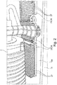
- the oil reservoir 16 has a substantially vertically disposed container wall 16a, wherein the at least one heat sink 25 is arranged on the container wall 16a and is flowed through from the cooling air flow of the fan 20 of the power electronics 15 in the vertical direction from top to bottom, as in the FIG. 1 illustrated by the arrows 30.
- the vertically arranged container wall 16a is in this case the front wall of the oil container 16, which faces the power electronics 15 or the drive axle 7.
- the at least one heat sink 25 is formed as a rib cooling body 26 with vertically arranged fins 27.
- the at least one heat sink 25 is arranged in the cooling air flow of the fan 20 downstream of the power electronics 15.
- the fan 20 sucks in the illustrated embodiment in the direction of travel in front of the truck 1 ambient air, as in the FIG. 1 is illustrated by the arrow 31, which is guided by corresponding, not shown heat sink of the power electronics 15 to cool the power electronics 15.
- the heated exhaust air cooling the power electronics 15 is then - as in the FIG. 1 is illustrated by the arrows 30 - from vertical top to bottom through the at least one heat sink 25, which is preferably designed as a rib heat sink 26 with vertically arranged fins 27, the oil tank 16 out to cool the pressure medium of the hydraulic system.
- the exhaust air of the cooling of the power electronics 15 is thus guided by the vertically arranged fins 27 of the fin cooling body 26.
- the cooling air for the cooling of the pressure vessel located in the oil reservoir 16 of the Hydraulic system is thus provided by the already existing fan 20 of the power electronics 15.
- the heated exhaust air cooling the oil tank 16 then flows back to the bottom of the truck 1 back into the environment.
- the heat sink 25 may - as in the FIG. 2 can be seen - are divided into a plurality of heat sinks or it can be arranged on the oil tank 16 one or more heat sinks 25. This makes it possible in a cost effective manner to equip trucks 1 different load classes or trucks 1 in the same capacity classes, which differed in terms of power density, with an adapted cooling of the pressure medium of the hydraulic system.
- the invention has a number of advantages: In the truck 1, a cooling of the pressure medium of the hydraulic system can be achieved with a simple structure in a cost-effective and energy-saving manner.
- the pressure medium of the hydraulic system For cooling the pressure medium of the hydraulic system, no pressure medium from a pump via a tubing must be circulated to a flowed through by the pressure medium of the hydraulic system heat exchanger, such as an oil cooler, resulting in energy savings and no additional oil cooler, no additional fan to the oil cooler and no additional Hydraulic valve for controlling the volume flow flowing through the oil cooler are required. Eliminating an extra fan on the oil cooler reduces noise and saves energy. The elimination of an oil cooler with the appropriate tubing also reduces the risk of leaks. Due to the elimination of the flowed through by the pressure medium of the hydraulic system oil cooler, the fan to the oil cooler and the required tubing also the assembly cost of the truck is reduced. In addition, the inventive cooling of the pressure medium of the hydraulic system has a low service cost.
- the at least one heat sink 25 can be arranged in a space-saving manner on the vertical wall 16a of the oil tank 16, so that a space-saving cooling of the pressure medium of the hydraulic system is achieved.
Landscapes
- Engineering & Computer Science (AREA)
- Transportation (AREA)
- Structural Engineering (AREA)
- Civil Engineering (AREA)
- Life Sciences & Earth Sciences (AREA)
- Geology (AREA)
- Mechanical Engineering (AREA)
- Forklifts And Lifting Vehicles (AREA)
Abstract
Description
- Die Erfindung betrifft ein Flurförderzeug, insbesondere Gegengewichtsgabelstapler, mit einer Leistungselektronik, die mittels mindestens eines Lüfters gekühlt ist, der einen die Leistungselektronik kühlenden Kühlluftstrom erzeugt, und mit einem Ölbehälter einer Hydraulikanlage.
- Flurförderzeuge weisen eine von der Arbeitshydraulik gebildete Hydraulikanlage auf, um die Arbeitsfunktionen eines Lastaufnahmemittels zu steuern, beispielsweise einen Hubantrieb zum Heben und Senken des Lastaufnahmemittels und/oder einen Neigeantrieb des Lastaufnahmemittels oder eines Hubgerüstes, an dem das Lastaufnahmemittel anhebbar und absenkbar angeordnet ist. Sofern das Flurförderzeug mit einer hydraulischen Lenkungsrichtung versehen ist, kann die Lenkungseinrichtung einen weiteren Verbraucher der Arbeitshydraulik bilden. Im Betrieb des Flurförderzeugs kommt es zu einer starken Erwärmung des Druckmittels, da insbesondere im Senkenbetrieb des Lastaufnahmemittels an dem den Hubantrieb steuernden Steuerwegeventil durch Drosselung des Senkenvolumenstroms ein hoher Wärmeeintrag in das von einem Hydrauliköl gebildete Druckmittel der Hydraulikanlage erfolgt.
- Um im Betrieb des Flurförderzeugs das Druckmittel der Hydraulikanlage zu kühlen, ist es bereits bei Flurförderzeugen bekannt, keine aktive Kühlung für das Druckmittel der Hydraulikanlage vorzusehen, so dass ein Wärmeaustausch und eine Kühlung ausschließlich über natürliche Konvektion und eine Wärmestrahlung an den Komponenten der Hydraulikanlage erfolgt. Bei einer derartigen, nicht-aktiven Kühlung gelangt das Flurförderzeug jedoch schnell an die Leistungsgrenze, da das Druckmittel der Hydraulikanlage überhitzt. Aufgrund der sich im Betrieb des Flurförderzeugs einstellenden hohen Temperaturen des Druckmittels der Hydraulikanlage kann eine vorzeitige Alterung des Druckmittels auftreten sowie Stillstandszeiten durch Leckage oder der Ausfall von Bauteilen der Hydraulikanlage.
- Zudem ist es bereits bei Flurförderzeugen bekannt, eine aktive Kühlung für das Druckmittel der Hydraulikanlage vorzusehen. Bei einer aktiven Kühlung des Druckmittels der Hydraulikanlage ist ein von dem Druckmittel der Hydraulikanlage durchströmter Wärmetauscher, beispielsweise ein Druckmittel-Luft-Wärmetauscher, vorhanden und ein angetriebener Lüfter, der einen Kühlluftstrom an dem Druckmittel-Luft-Wärmetauscher erzeugt, um die Kühlleistung zu erhöhen. Der Lüfter kann hierbei mechanisch von einem Verbrennungsmotor des Flurförderzeugs, hydraulisch oder elektrisch angetrieben sein. Bei einer derartigen aktiven Kühlung des Druckmittels der Hydraulikanlage ist somit ein von dem Druckmittel der Hydraulikanlage durchströmter Druckmittel-Luft-Wärmetauscher, beispielsweise ein Ölkühler, vorhanden. Dabei wird das Druckmittel der Hydraulikanlage durch den Druckmittel-Luft-Wärmetauscher geführt und mit Hilfe eines Lüfters Wärmeenergie aus dem Druckmittel der Hydraulikanlage an die Umgebung abgeführt. Der für die Kühlung des Druckmittels erforderliche Volumenstrom des Druckmittels der Hydraulikanlage kann hierbei von einem vorhandenen Volumenstrom abgezweigt werden, beispielsweise mittels eines zusätzlichen Hydraulikventils von dem von der Hydraulikpumpe der Arbeitshydraulik geförderten Volumenstrom abgezweigt werden, oder von einer zusätzlichen Umwälzpumpe erzeugt werden.
- Eine derartige aktive Kühlung des Druckmittels der Hydraulikanlage weist jedoch aufgrund des erforderlichen von dem Druckmittel der Hydraulikanlage durchströmten Druckmittel-Luft-Wärmetauschers, des zusätzlichen Lüfters an dem Druckmittel-Luft-Wärmetauscher, des Verschlauchungsaufwands und des aktiven Umpumpens des Druckmittels der Hydraulikanlage und des hierzu gegebenenfalls erforderlichen Hydraulikventils zur Steuerung des Volumenstroms einen hohen Bauaufwand und Bauraumbedarf auf und verursacht einen hohen zusätzlichen Herstellaufwand des Flurförderzeugs. Zudem erzeugt der den Kühlluftstrom an dem Druckmittel-Luft-Wärmetauscher erzeugende Lüfter zusätzliche Geräusche. Weiterhin benötigt der den Kühlluftstrom an dem Druckmittel-Luft-Wärmetauscher erzeugende Lüfter zusätzliche Energie für dessen Betrieb und es ist zusätzliche Energie erforderlich für das aktive Umpumpen des Druckmittels der Hydraulikanlage. Ein weiterer Nachteil einer derartigen aktiven Kühlung des Druckmittels der Hydraulikanlage besteht in der Gefahr von Leckagen.
- Der vorliegenden Erfindung liegt die Aufgabe zugrunde, ein Flurförderzeug der eingangs genannten Gattung zur Verfügung zu stellen, das mit einer einfach aufgebauten, kostengünstigen und energiesparenden Kühlung des Druckmittels der Hydraulikanlage versehen ist.
- Diese Aufgabe wird erfindungsgemäß dadurch gelöst, dass der Ölbehälter mit mindestens einem Kühlkörper versehen ist, der von dem Kühlluftstrom des Lüfters der Leistungselektronik durchströmt ist.
- Erfindungsgemäß wird somit das Druckmittel der Hydraulikanlage des Flurförderzeugs gekühlt, indem an dem Ölbehälter mindestens ein Kühlkörper angeordnet wird, der von dem Kühlluftstrom des bereits vorhandenen Lüfters der Leistungselektronik durchströmt ist.
- Hierdurch kann eine Kühlung des Druckmittels der Hydraulikanlage des Flurförderzeugs bei einfachem Aufbau und in kostengünstiger Weise umgesetzt werden, da kein von dem Druckmittel der Hydraulikanlage durchströmter Wärmetauscher und kein zusätzlicher angetriebener Lüfter erforderlich sind, der einen Kühlluftstrom an dem Wärmetauscher erzeugt. Zudem ist es bei der Erfindung nicht erforderlich, dass zur Kühlung des Druckmittels der Hydraulikanlage eine Pumpe einen Volumenstrom über eine Verschlauchung zu dem Wärmetauscher umpumpen muss, so dass weiterhin kein Hydraulikventil erforderlich ist, das den Volumenstrom des Druckmittels über den Wärmetauscher steuert. Durch den Entfall eines angetriebenen Lüfters, der einen Kühlluftstrom an dem Wärmetauscher erzeugt, werden Geräusche verringert. Weiterhin ist keine Energie erforderlich für einen den Kühlluftstrom an dem Wärmetauscher erzeugenden zusätzlichen Lüfter und keine Energie erforderlich für das aktive Umpumpen des Druckmittels der Hydraulikanlage. Zudem wird die Gefahr von Leckagen verringert.
- Gemäß einer vorteilhaften Ausführungsform der Erfindung weist der Ölbehälter eine im Wesentlichen vertikal angeordnete Behälterwand auf, wobei der mindestens eine Kühlkörper an der Behälterwand angeordnet ist und von dem Kühlluftstrom des Lüfters der Leistungselektronik in vertikaler Richtung von oben nach unten durchströmt ist. Hierdurch wird mit geringem Bauaufwand eine effektive und wirksame Kühlung des Druckmittels der Hydraulikanlage von dem Kühlluftstrom des Lüfters der Leistungselektronik erzielt.
- Gemäß einer vorteilhaften Ausgestaltungsform der Erfindung ist der mindestens eine Kühlkörper als Rippenkühlkörper mit vertikal angeordneten Lamellen ausgebildet. Mit einem am Ölbehälter angeordneten Rippenkühlkörper, der vertikal ausgerichtete Lamellen aufweist, kann mit geringem Bauaufwand eine effektive und wirksame Kühlung des Druckmittels der Hydraulikanlage von dem Kühlluftstrom des Lüfters der Leistungselektronik erzielt werden.
- Besondere Vorteile ergeben sich, wenn gemäß einer Ausgestaltungsform der Erfindung der mindestens eine Kühlkörper im Kühlluftstrom des Lüfters stromab der Leistungselektronik angeordnet ist. Hierdurch kann eine effektive Kühlung der Leistungselektronik mit kühler Luft aus der Umgebung erzielt werden, da die Leistungselektronik an erster Stelle von dem Kühlluftstrom durchströmt wird. Der Kühlkörper am Ölbehälter wird an zweiter Stelle und somit nach (stromab) der Leistungselektronik von dem Kühlluftstrom durchströmt und somit von der erwärmten Abluft der Leistungselektronik gekühlt, wodurch trotzdem eine effektive Kühlung des Druckmittels der Hydraulikanlage erzielt wird.
- Der Ölbehälter ist gemäß einer vorteilhaften Ausgestaltungsform der Erfindung Bestandteil eines Fahrzeugrahmens des Flurförderzeugs. Der Ölbehälter ist somit als Teil des Fahrzeugrahmens des Flurförderzeugs ausgebildet und in den Fahrzeugrahmen des Flurförderzeugs integriert.
- Gemäß einer vorteilhaften Ausgestaltungsform der Erfindung ist die Leistungselektronik an einer Antriebsachse des Flurförderzeugs angeordnet, wobei die Antriebsachse mindestens einen elektrischen Fahrmotor umfasst. Bevorzugt steuert die an der Antriebsachse angeordnete Leistungselektronik den mindestens einen elektrischen Fahrmotor der Antriebsachse an. Hierdurch kann eine Kühlluftführung erzielt werden, bei der der Lüfter der Leistungselektronik Umgebungsluft vor dem Flurförderzeug ansaugt, wodurch eine effektive Kühlung der Leistungselektronik und des Druckmittels der Hydraulikanlage erzielt wird.
- Der Ölbehälter ist gemäß einer vorteilhaften Ausgestaltungsform der Erfindung in Fahrzeuglängsrichtung des Flurförderzeugs zwischen der Antriebsachse und einem Batteriefach des Flurförderzeugs angeordnet. Dies ermöglicht es, dass der Kühlluftstrom nach Durchströmen der Leistungselektronik den mindestens einen Kühlkörper an dem Ölbehälter auf kurzem Wege von oben nach unten durchströmen kann, wodurch eine effektive Kühlung der Leistungselektronik und des Druckmittels der Hydraulikanlage erzielt wird.
- Bevorzugt ist der Lüfter der Leistungselektronik als elektrisch betriebener Lüfter ausgebildet. Dies ermöglicht es bei geringem Bauaufwand, den Kühlluftstrom zur Kühlung der Leistungselektronik und des Druckmittels der Hydraulikanlage zu erzeugen.
- Weitere Vorteile und Einzelheiten der Erfindung werden anhand des in den schematischen Figuren dargestellten Ausführungsbeispiels näher erläutert. Hierbei zeigt
- Figur 1
- ein erfindungsgemäßes Flurförderzeug in einer schematischen Seitenansicht und
- Figur 2
- eine Ansicht gemäß Pfeil A der
Figur 1 . - In der
Figur 1 ist ein erfindungsgemäßes Flurförderzeug 1 in einer schematischen Seitenansicht dargestellt. Das Flurförderzeug 1 ist im dargestellten Ausführungsbeispiel als Gegengewichtsgabelstapler ausgebildet. - Das Flurförderzeug 1 ist im frontseitigen Bereich mit einem Hubgerüst 2 und einem anhebbaren bzw. absenkbaren Lastaufnahmemittel L zur Aufnahme von Lasten versehen. Im heckseitigen Bereich ist das Flurförderzeug 1 mit einem Gegengewicht 3 versehen. Das Flurförderzeug 1 umfasst einen Fahrzeugrahmen 4. An dem Fahrzeugrahmen 4 ist ein nicht näher dargestelltes Fahrerschutzdach bzw. eine Fahrerkabine angeordnet, innerhalb deren sich ein Fahrerarbeitsplatz für eine Bedienperson befindet.
- Das Flurförderzeug 1 ist im dargestellten Ausführungsbeispiel im frontseitigen Bereich mit einer Antriebsachse 7 mit angetriebenen Rädern 8 versehen. Im heckseitigen Bereich des Gegengewichts 3 ist ein gelenktes Rad oder eine mit gelenkten Rädern 9 versehene Lenkachse 10 vorgesehen. Die Antriebsachse 7 ist mit einem Fahrantrieb des Flurförderzeugs 1 versehen und umfasst einen in der Antriebsachse 7 angeordneten elektrischen Fahrmotor oder mehrere in der Antriebsachse 7 angeordnete elektrische Fahrmotoren zum Antrieb der Räder 8.
- Zur Steuerung des elektrischen Fahrmotors oder der elektrischen Fahrmotoren ist an der Antriebsachse 7 eine Leistungselektronik 15 angeordnet. Im dargestellten Ausführungsbeispiel ist die Leistungselektronik 15 an der Oberseite der Antriebsachse 7 angeordnet.
- Das Flurförderzeug 1 ist mit einer als Arbeitshydraulik ausgebildeten Hydraulikanlage versehen, die als hydraulische Verbraucher einen Hubantrieb zum Heben und Senken des Lastaufnahmemittels L und zum Neigen des Hubgerüstes 2 umfasst. Weitere hydraulische Verbraucher der Arbeitshydraulik können von Zusatzverbrauchern gebildet sein, beispielsweise einem Seitenschieber für das Lastaufnahmemittel L. Sofern zum Lenken der gelenkten Räder 9 eine hydraulische Lenkungseinrichtung vorgesehen ist, kann die hydraulische Lenkungseinrichtung als weiterer Verbraucher der Arbeitshydraulik vorgesehen werden.
- Die Hydraulikanlage umfasst einen Ölbehälter 16.
- Das Flurförderzeug1 ist im dargestellten Ausführungsbeispiel als batterie-elektrisch betriebenes Flurförderzeug 1 ausgebildet. Zur Versorgung des elektrischen Fahrmotors des Fahrantriebs und eines Elektromotors, der die Hydraulikpumpe der Hydraulikanlage antreibt, ist eine Traktionsbatterie 17 vorgesehen, die in einem Batteriefach 18 des Fahrzeugrahmens 4 angeordnet ist.
- Der Ölbehälter 16 der Hydraulikanlage ist in Fahrzeuglängsrichtung des Flurförderzeugs zwischen der Antriebsachse 7 und dem Batteriefach 18 des Flurförderzeugs 1 angeordnet.
- Im dargestellten Ausführungsbeispiel ist der Ölbehälter 16 Bestandteil des Fahrzeugrahmens 4 des Flurförderzeugs 1 und somit in den Fahrzeugrahmen 4 integriert. Der Ölbehälter 16 ist bevorzugt als rechteckförmiger Kasten des Fahrzeugrahmens 4 ausgebildet, der sich in Fahrzeugquerrichtung erstreckt.
- Die Leistungselektronik 15 ist mittels mindestens eines Lüfters 20 gekühlt, der einen die Leistungselektronik 15 kühlenden Kühlluftstrom erzeugt. Der Lüfter 20 ist im dargestellten Ausführungsbeispiel als elektrisch betriebener Lüfter ausgebildet, der an der Antriebsachse 7 bzw. der Leistungselektronik 15 angeordnet ist.
- Erfindungsgemäß ist der Ölbehälter 16 mit mindestens einem Kühlkörper 25 versehen, der von dem Kühlluftstrom des Lüfters 20 der Leistungselektronik 15 durchströmt ist. Der mindestens eine Kühlkörper 25 ist hierzu thermisch leitend mit dem Ölbehälter 16 verbunden.
- Im dargestellten Ausführungsbeispiel weist der Ölbehälter 16 eine im Wesentlichen vertikal angeordnete Behälterwand 16a auf, wobei der mindestens eine Kühlkörper 25 an der Behälterwand 16a angeordnet ist und von dem Kühlluftstrom des Lüfters 20 der Leistungselektronik 15 in vertikaler Richtung von oben nach unten durchströmt ist, wie in der
Figur 1 anhand der Pfeile 30 verdeutlicht ist. Die vertikal angeordnete Behälterwand 16a ist hierbei die Vorderwand des Ölbehälters 16, die der Leistungselektronik 15 bzw. der Antriebsachse 7 zugewandt ist. - Wie in Verbindung mit der
Figur 2 ersichtlich ist, ist der der mindestens eine Kühlkörper 25 als Rippenkühlkörper 26 mit vertikal angeordneten Lamellen 27 ausgebildet. - Der mindestens eine Kühlkörper 25 ist im Kühlluftstrom des Lüfters 20 stromab der Leistungselektronik 15 angeordnet.
- Der Lüfter 20 saugt im dargestellten Ausführungsbeispiel in Fahrtrichtung vor dem Flurförderzeug 1 Umgebungsluft an, wie in der
Figur 1 mit dem Pfeil 31 verdeutlicht ist, die durch entsprechende, nicht näher dargestellte Kühlkörper der Leistungselektronik 15 geführt wird, um die Leistungselektronik 15 zu kühlen. Die erwärmte Abluft der Kühlung der Leistungselektronik 15 wird anschließend - wie in derFigur 1 von den Pfeilen 30 verdeutlicht ist - von vertikal oben nach unten durch den mindestens einen Kühlkörper 25, der bevorzugt als Rippenkühlkörper 26 mit vertikal angeordneten Lamellen 27 ausgebildet ist, des Ölbehälters 16 geführt, um das Druckmittel der Hydraulikanlage zu kühlen. Die Abluft der Kühlung der Leistungselektronik 15 wird somit durch die vertikal angeordneten Lamellen 27 des Rippenkühlkörpers 26 geführt. Die Kühlluft für die Kühlung des im Ölbehälter 16 befindlichen Druckmittels der Hydraulikanlage wird somit von dem bereits vorhandenen Lüfter 20 der Leistungselektronik 15 bereitgestellt. - Die erwärmte Abluft der Kühlung des Ölbehälters 16 strömt anschließend an der Unterseite des Flurförderzeugs 1 zurück in die Umgebung.
- Der Kühlkörper 25 kann - wie in der
Figur 2 ersichtlich ist - in mehrere Teilkühlkörper aufgeteilt werden bzw. es können ein oder mehrere Kühlkörper 25 an dem Ölbehälter 16 angeordnet werden. Dadurch ist es in kostengünstiger Weise möglich, Flurförderzeuge 1 verschiedener Tragfähigkeitsklassen oder Flurförderzeuge 1 in derselben Tragfähigkeitsklassen, die sich hinsichtlich der Leistungsdichte unterschieden, mit einer angepassten Kühlung des Druckmittels der Hydraulikanlage auszustatten. - Die Erfindung weist eine Reihe von Vorteilen auf:
Bei dem Flurförderzeug 1 kann eine Kühlung des Druckmittels der Hydraulikanlage mit einem einfachen Aufbau in kostengünstiger und energiesparender Weise erzielt werden. - Zur Kühlung des Druckmittels der Hydraulikanlage muss kein Druckmittel von einer Pumpe über eine Verschlauchung zu einem von dem Druckmittel der Hydraulikanlage durchströmter Wärmetauscher, beispielsweise einem Ölkühler umgewälzt werden, wodurch sich eine Energieeinsparung ergibt und kein zusätzlicher Ölkühler, kein zusätzlicher Lüfter an dem Ölkühler und kein zusätzliches Hydraulikventil zur Steuerung des über den Ölkühler strömenden Volumenstroms erforderlich sind. Durch den Entfall eines zusätzlichen Lüfters an dem Ölkühler werden Geräusche verringert und eine Energieeinsparung erzielt. Der Entfall eines Ölkühlers mit der entsprechenden Verschlauchung verringert zudem die Gefahr von Leckagen. Durch den Entfall des von dem Druckmittel der Hydraulikanlage durchströmten Ölkühlers, des Lüfters an dem Ölkühler und der erforderlichen Verschlauchung wird zudem der Montageaufwand des Flurförderzeugs verringert. Darüber hinaus weist die erfindungsgemäße Kühlung des Druckmittels der Hydraulikanlage einen geringen Serviceaufwand auf.
- Zudem kann der mindestens eine Kühlkörper 25 in bauraumsparender Weise an der vertikalen Wand 16a des Ölbehälters 16 angeordnet werden, so dass eine bauraumsparende Kühlung des Druckmittels der Hydraulikanlage erzielt wird.
Claims (8)
- Flurförderzeug (1), insbesondere Gegengewichtsgabelstapler, mit einer Leistungselektronik (15), die mittels mindestens eines Lüfters (20) gekühlt ist, der einen die Leistungselektronik (15) kühlenden Kühlluftstrom erzeugt, und mit einem Ölbehälter (16) einer Hydraulikanlage, dadurch gekennzeichnet, dass der Ölbehälter (16) mit mindestens einem Kühlkörper (25) versehen ist, der von dem Kühlluftstrom (30) des Lüfters (20) der Leistungselektronik (15) durchströmt ist.
- Flurförderzeug nach Anspruch 1, dadurch gekennzeichnet, dass der Ölbehälter (16) eine im Wesentlichen vertikal angeordnete Behälterwand (16a) aufweist, wobei der mindestens eine Kühlkörper (25) an der Behälterwand (16a) angeordnet ist und von dem Kühlluftstrom (30) des Lüfters (20) der Leistungselektronik (15) in vertikaler Richtung von oben nach unten durchströmt ist.
- Flurförderzeug nach Anspruch 1 oder 2, dadurch gekennzeichnet, dass der mindestens eine Kühlkörper (25) als Rippenkühlkörper (26) mit vertikal angeordneten Lamellen (27) ausgebildet ist.
- Flurförderzeug nach einem der Ansprüche 1 bis 3, dadurch gekennzeichnet, dass der mindestens eine Kühlkörper (25) im Kühlluftstrom (30) des Lüfters (20) stromab der Leistungselektronik (15) angeordnet ist.
- Flurförderzeug nach einem der Ansprüche 1 bis 4, dadurch gekennzeichnet, dass der Ölbehälter (16) Bestandteil eines Fahrzeugrahmens (4) des Flurförderzeugs (1) ist.
- Flurförderzeug nach einem der Ansprüche 1 bis 5, dadurch gekennzeichnet, dass die Leistungselektronik (15) an einer Antriebsachse (7) des Flurförderzeugs (1) angeordnet ist, wobei die Antriebsachse (7) mindestens einen elektrischen Fahrmotor umfasst.
- Flurförderzeug nach Anspruch 6, dadurch gekennzeichnet, dass der Ölbehälter (16) in Fahrzeuglängsrichtung des Flurförderzeugs (1) zwischen der Antriebsachse (7) und einem Batteriefach (18) des Flurförderzeugs (1) angeordnet ist.
- Flurförderzeug nach einem der Ansprüche 1 bis 7, dadurch gekennzeichnet, dass der Lüfter (20) der Leistungselektronik (15) als elektrisch betriebener Lüfter ausgebildet ist.
Applications Claiming Priority (1)
| Application Number | Priority Date | Filing Date | Title |
|---|---|---|---|
| DE102018102933.0A DE102018102933A1 (de) | 2018-02-09 | 2018-02-09 | Flurförderzeug |
Publications (2)
| Publication Number | Publication Date |
|---|---|
| EP3524566A1 true EP3524566A1 (de) | 2019-08-14 |
| EP3524566B1 EP3524566B1 (de) | 2023-08-09 |
Family
ID=65279430
Family Applications (1)
| Application Number | Title | Priority Date | Filing Date |
|---|---|---|---|
| EP19155223.1A Active EP3524566B1 (de) | 2018-02-09 | 2019-02-04 | Flurförderzeug |
Country Status (2)
| Country | Link |
|---|---|
| EP (1) | EP3524566B1 (de) |
| DE (1) | DE102018102933A1 (de) |
Citations (3)
| Publication number | Priority date | Publication date | Assignee | Title |
|---|---|---|---|---|
| EP0494662A2 (de) * | 1991-01-10 | 1992-07-15 | Kabushiki Kaisha Toyoda Jidoshokki Seisakusho | Gabelhubwagen |
| DE102004030560A1 (de) * | 2004-06-24 | 2006-01-19 | Linde Ag | Flurförderzeug, insbesondere Flurförderzeug mit einem batterie-elektrischen Antriebssystem |
| DE112013000002T5 (de) * | 2013-01-08 | 2014-11-06 | Komatsu Ltd. | Batteriebetriebener Gabelstapler |
-
2018
- 2018-02-09 DE DE102018102933.0A patent/DE102018102933A1/de not_active Withdrawn
-
2019
- 2019-02-04 EP EP19155223.1A patent/EP3524566B1/de active Active
Patent Citations (3)
| Publication number | Priority date | Publication date | Assignee | Title |
|---|---|---|---|---|
| EP0494662A2 (de) * | 1991-01-10 | 1992-07-15 | Kabushiki Kaisha Toyoda Jidoshokki Seisakusho | Gabelhubwagen |
| DE102004030560A1 (de) * | 2004-06-24 | 2006-01-19 | Linde Ag | Flurförderzeug, insbesondere Flurförderzeug mit einem batterie-elektrischen Antriebssystem |
| DE112013000002T5 (de) * | 2013-01-08 | 2014-11-06 | Komatsu Ltd. | Batteriebetriebener Gabelstapler |
Also Published As
| Publication number | Publication date |
|---|---|
| EP3524566B1 (de) | 2023-08-09 |
| DE102018102933A1 (de) | 2019-08-14 |
Similar Documents
| Publication | Publication Date | Title |
|---|---|---|
| EP3705631B1 (de) | Arbeitsmaschine mit elektroantrieb und kühlvorrichtung | |
| EP3524566B1 (de) | Flurförderzeug | |
| DE102011011721A1 (de) | Fahrzeugrahmen eines Gegengewichtsgabelstaplers | |
| EP2774789B1 (de) | Heizvorrichtung für eine mobile Arbeitsmaschine | |
| DE102011108188A1 (de) | Elektrisch betriebenes Fahrzeug insbesondere Flurförderzeug | |
| DE102020127127A1 (de) | Hydraulikanlage eines Flurförderzeugs | |
| DE102012112932A1 (de) | Hydrostatisches Antriebssystem einer mobilen Arbeitsmaschine mit Druckmittelkühlung | |
| DE102013113206A1 (de) | Batterie-elektrisch betriebenes Flurförderzeug | |
| DE102005045414B4 (de) | Arbeitsmaschine mit einem elektrischen Fahrmotor eines Fahrantriebs, einem elektrischen Pumpenmotor einer Arbeitshydraulik und einer Flüssigkeitskühlung | |
| DE102011056282A1 (de) | Kühlsystem für ein Flurförderzeug | |
| DE102004030560A1 (de) | Flurförderzeug, insbesondere Flurförderzeug mit einem batterie-elektrischen Antriebssystem | |
| EP3327296A1 (de) | Hydrauliköltank mit integrierter kühlung | |
| EP2444359B1 (de) | Gegengewichtsgabelstapler mit Flüssigkeitskühlereinrichtung | |
| EP4137641B1 (de) | Arbeitsmaschine | |
| EP2058269A2 (de) | Flurförderzeug mit einem Verbrennungsmotor und einem elektrischen Aggregat | |
| EP2489626A1 (de) | Gegengewichtsgabelstapler mit einem Hybridantrieb | |
| DE102006003410B4 (de) | Hubwagen mit Aggregateräumen | |
| DE102014105660A1 (de) | Hydraulisches Antriebssystem eines Flurförderzeugs | |
| DE102021102209A1 (de) | Flurförderzeug | |
| EP3073157A1 (de) | Hydrauliksystem mit ölentlüftung | |
| DE2734236A1 (de) | Hubstapler | |
| DE102011011720A1 (de) | Wechselsystem zum seitlichen Wechsel eines Antriebsmoduls eines Flurförderzeugs | |
| DE102021101763A1 (de) | Flurförderzeug | |
| DE102013109154A1 (de) | Flurförderzeug | |
| DE102021101483A1 (de) | Flurförderzeug mit einer eine Hubhydraulik umfassenden Hydraulikanlage |
Legal Events
| Date | Code | Title | Description |
|---|---|---|---|
| PUAI | Public reference made under article 153(3) epc to a published international application that has entered the european phase |
Free format text: ORIGINAL CODE: 0009012 |
|
| STAA | Information on the status of an ep patent application or granted ep patent |
Free format text: STATUS: THE APPLICATION HAS BEEN PUBLISHED |
|
| AK | Designated contracting states |
Kind code of ref document: A1 Designated state(s): AL AT BE BG CH CY CZ DE DK EE ES FI FR GB GR HR HU IE IS IT LI LT LU LV MC MK MT NL NO PL PT RO RS SE SI SK SM TR |
|
| AX | Request for extension of the european patent |
Extension state: BA ME |
|
| STAA | Information on the status of an ep patent application or granted ep patent |
Free format text: STATUS: REQUEST FOR EXAMINATION WAS MADE |
|
| 17P | Request for examination filed |
Effective date: 20200205 |
|
| RBV | Designated contracting states (corrected) |
Designated state(s): AL AT BE BG CH CY CZ DE DK EE ES FI FR GB GR HR HU IE IS IT LI LT LU LV MC MK MT NL NO PL PT RO RS SE SI SK SM TR |
|
| GRAP | Despatch of communication of intention to grant a patent |
Free format text: ORIGINAL CODE: EPIDOSNIGR1 |
|
| STAA | Information on the status of an ep patent application or granted ep patent |
Free format text: STATUS: GRANT OF PATENT IS INTENDED |
|
| INTG | Intention to grant announced |
Effective date: 20230328 |
|
| GRAS | Grant fee paid |
Free format text: ORIGINAL CODE: EPIDOSNIGR3 |
|
| GRAA | (expected) grant |
Free format text: ORIGINAL CODE: 0009210 |
|
| STAA | Information on the status of an ep patent application or granted ep patent |
Free format text: STATUS: THE PATENT HAS BEEN GRANTED |
|
| AK | Designated contracting states |
Kind code of ref document: B1 Designated state(s): AL AT BE BG CH CY CZ DE DK EE ES FI FR GB GR HR HU IE IS IT LI LT LU LV MC MK MT NL NO PL PT RO RS SE SI SK SM TR |
|
| REG | Reference to a national code |
Ref country code: GB Ref legal event code: FG4D Free format text: NOT ENGLISH |
|
| REG | Reference to a national code |
Ref country code: CH Ref legal event code: EP |
|
| REG | Reference to a national code |
Ref country code: IE Ref legal event code: FG4D Free format text: LANGUAGE OF EP DOCUMENT: GERMAN |
|
| REG | Reference to a national code |
Ref country code: DE Ref legal event code: R096 Ref document number: 502019008823 Country of ref document: DE |
|
| P01 | Opt-out of the competence of the unified patent court (upc) registered |
Effective date: 20230816 |
|
| REG | Reference to a national code |
Ref country code: LT Ref legal event code: MG9D |
|
| REG | Reference to a national code |
Ref country code: NL Ref legal event code: MP Effective date: 20230809 |
|
| PG25 | Lapsed in a contracting state [announced via postgrant information from national office to epo] |
Ref country code: GR Free format text: LAPSE BECAUSE OF FAILURE TO SUBMIT A TRANSLATION OF THE DESCRIPTION OR TO PAY THE FEE WITHIN THE PRESCRIBED TIME-LIMIT Effective date: 20231110 |
|
| PG25 | Lapsed in a contracting state [announced via postgrant information from national office to epo] |
Ref country code: IS Free format text: LAPSE BECAUSE OF FAILURE TO SUBMIT A TRANSLATION OF THE DESCRIPTION OR TO PAY THE FEE WITHIN THE PRESCRIBED TIME-LIMIT Effective date: 20231209 |
|
| PG25 | Lapsed in a contracting state [announced via postgrant information from national office to epo] |
Ref country code: SE Free format text: LAPSE BECAUSE OF FAILURE TO SUBMIT A TRANSLATION OF THE DESCRIPTION OR TO PAY THE FEE WITHIN THE PRESCRIBED TIME-LIMIT Effective date: 20230809 Ref country code: RS Free format text: LAPSE BECAUSE OF FAILURE TO SUBMIT A TRANSLATION OF THE DESCRIPTION OR TO PAY THE FEE WITHIN THE PRESCRIBED TIME-LIMIT Effective date: 20230809 Ref country code: PT Free format text: LAPSE BECAUSE OF FAILURE TO SUBMIT A TRANSLATION OF THE DESCRIPTION OR TO PAY THE FEE WITHIN THE PRESCRIBED TIME-LIMIT Effective date: 20231211 Ref country code: NO Free format text: LAPSE BECAUSE OF FAILURE TO SUBMIT A TRANSLATION OF THE DESCRIPTION OR TO PAY THE FEE WITHIN THE PRESCRIBED TIME-LIMIT Effective date: 20231109 Ref country code: NL Free format text: LAPSE BECAUSE OF FAILURE TO SUBMIT A TRANSLATION OF THE DESCRIPTION OR TO PAY THE FEE WITHIN THE PRESCRIBED TIME-LIMIT Effective date: 20230809 Ref country code: LV Free format text: LAPSE BECAUSE OF FAILURE TO SUBMIT A TRANSLATION OF THE DESCRIPTION OR TO PAY THE FEE WITHIN THE PRESCRIBED TIME-LIMIT Effective date: 20230809 Ref country code: LT Free format text: LAPSE BECAUSE OF FAILURE TO SUBMIT A TRANSLATION OF THE DESCRIPTION OR TO PAY THE FEE WITHIN THE PRESCRIBED TIME-LIMIT Effective date: 20230809 Ref country code: IS Free format text: LAPSE BECAUSE OF FAILURE TO SUBMIT A TRANSLATION OF THE DESCRIPTION OR TO PAY THE FEE WITHIN THE PRESCRIBED TIME-LIMIT Effective date: 20231209 Ref country code: HR Free format text: LAPSE BECAUSE OF FAILURE TO SUBMIT A TRANSLATION OF THE DESCRIPTION OR TO PAY THE FEE WITHIN THE PRESCRIBED TIME-LIMIT Effective date: 20230809 Ref country code: GR Free format text: LAPSE BECAUSE OF FAILURE TO SUBMIT A TRANSLATION OF THE DESCRIPTION OR TO PAY THE FEE WITHIN THE PRESCRIBED TIME-LIMIT Effective date: 20231110 Ref country code: FI Free format text: LAPSE BECAUSE OF FAILURE TO SUBMIT A TRANSLATION OF THE DESCRIPTION OR TO PAY THE FEE WITHIN THE PRESCRIBED TIME-LIMIT Effective date: 20230809 |
|
| PG25 | Lapsed in a contracting state [announced via postgrant information from national office to epo] |
Ref country code: PL Free format text: LAPSE BECAUSE OF FAILURE TO SUBMIT A TRANSLATION OF THE DESCRIPTION OR TO PAY THE FEE WITHIN THE PRESCRIBED TIME-LIMIT Effective date: 20230809 |
|
| PG25 | Lapsed in a contracting state [announced via postgrant information from national office to epo] |
Ref country code: ES Free format text: LAPSE BECAUSE OF FAILURE TO SUBMIT A TRANSLATION OF THE DESCRIPTION OR TO PAY THE FEE WITHIN THE PRESCRIBED TIME-LIMIT Effective date: 20230809 |
|
| PG25 | Lapsed in a contracting state [announced via postgrant information from national office to epo] |
Ref country code: SM Free format text: LAPSE BECAUSE OF FAILURE TO SUBMIT A TRANSLATION OF THE DESCRIPTION OR TO PAY THE FEE WITHIN THE PRESCRIBED TIME-LIMIT Effective date: 20230809 Ref country code: RO Free format text: LAPSE BECAUSE OF FAILURE TO SUBMIT A TRANSLATION OF THE DESCRIPTION OR TO PAY THE FEE WITHIN THE PRESCRIBED TIME-LIMIT Effective date: 20230809 Ref country code: ES Free format text: LAPSE BECAUSE OF FAILURE TO SUBMIT A TRANSLATION OF THE DESCRIPTION OR TO PAY THE FEE WITHIN THE PRESCRIBED TIME-LIMIT Effective date: 20230809 Ref country code: EE Free format text: LAPSE BECAUSE OF FAILURE TO SUBMIT A TRANSLATION OF THE DESCRIPTION OR TO PAY THE FEE WITHIN THE PRESCRIBED TIME-LIMIT Effective date: 20230809 Ref country code: DK Free format text: LAPSE BECAUSE OF FAILURE TO SUBMIT A TRANSLATION OF THE DESCRIPTION OR TO PAY THE FEE WITHIN THE PRESCRIBED TIME-LIMIT Effective date: 20230809 Ref country code: SK Free format text: LAPSE BECAUSE OF FAILURE TO SUBMIT A TRANSLATION OF THE DESCRIPTION OR TO PAY THE FEE WITHIN THE PRESCRIBED TIME-LIMIT Effective date: 20230809 |
|
| REG | Reference to a national code |
Ref country code: DE Ref legal event code: R097 Ref document number: 502019008823 Country of ref document: DE |
|
| PLBE | No opposition filed within time limit |
Free format text: ORIGINAL CODE: 0009261 |
|
| STAA | Information on the status of an ep patent application or granted ep patent |
Free format text: STATUS: NO OPPOSITION FILED WITHIN TIME LIMIT |
|
| 26N | No opposition filed |
Effective date: 20240513 |
|
| PG25 | Lapsed in a contracting state [announced via postgrant information from national office to epo] |
Ref country code: SI Free format text: LAPSE BECAUSE OF FAILURE TO SUBMIT A TRANSLATION OF THE DESCRIPTION OR TO PAY THE FEE WITHIN THE PRESCRIBED TIME-LIMIT Effective date: 20230809 |
|
| PG25 | Lapsed in a contracting state [announced via postgrant information from national office to epo] |
Ref country code: MC Free format text: LAPSE BECAUSE OF FAILURE TO SUBMIT A TRANSLATION OF THE DESCRIPTION OR TO PAY THE FEE WITHIN THE PRESCRIBED TIME-LIMIT Effective date: 20230809 |
|
| REG | Reference to a national code |
Ref country code: CH Ref legal event code: PL |
|
| PG25 | Lapsed in a contracting state [announced via postgrant information from national office to epo] |
Ref country code: LU Free format text: LAPSE BECAUSE OF NON-PAYMENT OF DUE FEES Effective date: 20240204 |
|
| PG25 | Lapsed in a contracting state [announced via postgrant information from national office to epo] |
Ref country code: CH Free format text: LAPSE BECAUSE OF NON-PAYMENT OF DUE FEES Effective date: 20240229 |
|
| GBPC | Gb: european patent ceased through non-payment of renewal fee |
Effective date: 20240204 |
|
| PG25 | Lapsed in a contracting state [announced via postgrant information from national office to epo] |
Ref country code: LU Free format text: LAPSE BECAUSE OF NON-PAYMENT OF DUE FEES Effective date: 20240204 Ref country code: CH Free format text: LAPSE BECAUSE OF NON-PAYMENT OF DUE FEES Effective date: 20240229 |
|
| PG25 | Lapsed in a contracting state [announced via postgrant information from national office to epo] |
Ref country code: BG Free format text: LAPSE BECAUSE OF FAILURE TO SUBMIT A TRANSLATION OF THE DESCRIPTION OR TO PAY THE FEE WITHIN THE PRESCRIBED TIME-LIMIT Effective date: 20230809 |
|
| PG25 | Lapsed in a contracting state [announced via postgrant information from national office to epo] |
Ref country code: BG Free format text: LAPSE BECAUSE OF FAILURE TO SUBMIT A TRANSLATION OF THE DESCRIPTION OR TO PAY THE FEE WITHIN THE PRESCRIBED TIME-LIMIT Effective date: 20230809 |
|
| REG | Reference to a national code |
Ref country code: BE Ref legal event code: MM Effective date: 20240229 |
|
| PG25 | Lapsed in a contracting state [announced via postgrant information from national office to epo] |
Ref country code: BE Free format text: LAPSE BECAUSE OF NON-PAYMENT OF DUE FEES Effective date: 20240229 |
|
| PG25 | Lapsed in a contracting state [announced via postgrant information from national office to epo] |
Ref country code: GB Free format text: LAPSE BECAUSE OF NON-PAYMENT OF DUE FEES Effective date: 20240204 |
|
| PG25 | Lapsed in a contracting state [announced via postgrant information from national office to epo] |
Ref country code: FR Free format text: LAPSE BECAUSE OF NON-PAYMENT OF DUE FEES Effective date: 20240229 |
|
| PG25 | Lapsed in a contracting state [announced via postgrant information from national office to epo] |
Ref country code: IE Free format text: LAPSE BECAUSE OF NON-PAYMENT OF DUE FEES Effective date: 20240204 |
|
| PG25 | Lapsed in a contracting state [announced via postgrant information from national office to epo] |
Ref country code: IE Free format text: LAPSE BECAUSE OF NON-PAYMENT OF DUE FEES Effective date: 20240204 Ref country code: GB Free format text: LAPSE BECAUSE OF NON-PAYMENT OF DUE FEES Effective date: 20240204 Ref country code: FR Free format text: LAPSE BECAUSE OF NON-PAYMENT OF DUE FEES Effective date: 20240229 Ref country code: BE Free format text: LAPSE BECAUSE OF NON-PAYMENT OF DUE FEES Effective date: 20240229 |
|
| REG | Reference to a national code |
Ref country code: AT Ref legal event code: MM01 Ref document number: 1597338 Country of ref document: AT Kind code of ref document: T Effective date: 20240204 |
|
| PG25 | Lapsed in a contracting state [announced via postgrant information from national office to epo] |
Ref country code: AT Free format text: LAPSE BECAUSE OF NON-PAYMENT OF DUE FEES Effective date: 20240204 |
|
| PG25 | Lapsed in a contracting state [announced via postgrant information from national office to epo] |
Ref country code: CY Free format text: LAPSE BECAUSE OF FAILURE TO SUBMIT A TRANSLATION OF THE DESCRIPTION OR TO PAY THE FEE WITHIN THE PRESCRIBED TIME-LIMIT; INVALID AB INITIO Effective date: 20190204 |
|
| PG25 | Lapsed in a contracting state [announced via postgrant information from national office to epo] |
Ref country code: HU Free format text: LAPSE BECAUSE OF FAILURE TO SUBMIT A TRANSLATION OF THE DESCRIPTION OR TO PAY THE FEE WITHIN THE PRESCRIBED TIME-LIMIT; INVALID AB INITIO Effective date: 20190204 |
|
| PG25 | Lapsed in a contracting state [announced via postgrant information from national office to epo] |
Ref country code: TR Free format text: LAPSE BECAUSE OF FAILURE TO SUBMIT A TRANSLATION OF THE DESCRIPTION OR TO PAY THE FEE WITHIN THE PRESCRIBED TIME-LIMIT Effective date: 20230809 |
|
| PGFP | Annual fee paid to national office [announced via postgrant information from national office to epo] |
Ref country code: DE Payment date: 20260217 Year of fee payment: 8 |
|
| PGFP | Annual fee paid to national office [announced via postgrant information from national office to epo] |
Ref country code: IT Payment date: 20260227 Year of fee payment: 8 |
|
| PGFP | Annual fee paid to national office [announced via postgrant information from national office to epo] |
Ref country code: CZ Payment date: 20260122 Year of fee payment: 8 |