EP3522342A1 - Getriebeantriebsvorrichtung für bewegliche teile in kraftfahrzeugen - Google Patents
Getriebeantriebsvorrichtung für bewegliche teile in kraftfahrzeugen Download PDFInfo
- Publication number
- EP3522342A1 EP3522342A1 EP17854521.6A EP17854521A EP3522342A1 EP 3522342 A1 EP3522342 A1 EP 3522342A1 EP 17854521 A EP17854521 A EP 17854521A EP 3522342 A1 EP3522342 A1 EP 3522342A1
- Authority
- EP
- European Patent Office
- Prior art keywords
- gear
- driving device
- gear assembly
- planetary gear
- planetary
- Prior art date
- Legal status (The legal status is an assumption and is not a legal conclusion. Google has not performed a legal analysis and makes no representation as to the accuracy of the status listed.)
- Withdrawn
Links
Images
Classifications
-
- H—ELECTRICITY
- H02—GENERATION; CONVERSION OR DISTRIBUTION OF ELECTRIC POWER
- H02K—DYNAMO-ELECTRIC MACHINES
- H02K7/00—Arrangements for handling mechanical energy structurally associated with dynamo-electric machines, e.g. structural association with mechanical driving motors or auxiliary dynamo-electric machines
- H02K7/10—Structural association with clutches, brakes, gears, pulleys or mechanical starters
- H02K7/116—Structural association with clutches, brakes, gears, pulleys or mechanical starters with gears
-
- F—MECHANICAL ENGINEERING; LIGHTING; HEATING; WEAPONS; BLASTING
- F16—ENGINEERING ELEMENTS AND UNITS; GENERAL MEASURES FOR PRODUCING AND MAINTAINING EFFECTIVE FUNCTIONING OF MACHINES OR INSTALLATIONS; THERMAL INSULATION IN GENERAL
- F16H—GEARING
- F16H1/00—Toothed gearings for conveying rotary motion
- F16H1/28—Toothed gearings for conveying rotary motion with gears having orbital motion
- F16H1/46—Systems consisting of a plurality of gear trains each with orbital gears, i.e. systems having three or more central gears
-
- F—MECHANICAL ENGINEERING; LIGHTING; HEATING; WEAPONS; BLASTING
- F16—ENGINEERING ELEMENTS AND UNITS; GENERAL MEASURES FOR PRODUCING AND MAINTAINING EFFECTIVE FUNCTIONING OF MACHINES OR INSTALLATIONS; THERMAL INSULATION IN GENERAL
- F16H—GEARING
- F16H57/00—General details of gearing
- F16H57/02—Gearboxes; Mounting gearing therein
- F16H57/021—Shaft support structures, e.g. partition walls, bearing eyes, casing walls or covers with bearings
-
- B—PERFORMING OPERATIONS; TRANSPORTING
- B60—VEHICLES IN GENERAL
- B60J—WINDOWS, WINDSCREENS, NON-FIXED ROOFS, DOORS, OR SIMILAR DEVICES FOR VEHICLES; REMOVABLE EXTERNAL PROTECTIVE COVERINGS SPECIALLY ADAPTED FOR VEHICLES
- B60J9/00—Devices not provided for in one of main groups B60J1/00 - B60J7/00
-
- B—PERFORMING OPERATIONS; TRANSPORTING
- B60—VEHICLES IN GENERAL
- B60R—VEHICLES, VEHICLE FITTINGS, OR VEHICLE PARTS, NOT OTHERWISE PROVIDED FOR
- B60R3/00—Arrangements of steps or ladders facilitating access to or on the vehicle, e.g. running-boards
- B60R3/02—Retractable steps or ladders, e.g. movable under shock
-
- F—MECHANICAL ENGINEERING; LIGHTING; HEATING; WEAPONS; BLASTING
- F16—ENGINEERING ELEMENTS AND UNITS; GENERAL MEASURES FOR PRODUCING AND MAINTAINING EFFECTIVE FUNCTIONING OF MACHINES OR INSTALLATIONS; THERMAL INSULATION IN GENERAL
- F16H—GEARING
- F16H1/00—Toothed gearings for conveying rotary motion
- F16H1/28—Toothed gearings for conveying rotary motion with gears having orbital motion
- F16H1/32—Toothed gearings for conveying rotary motion with gears having orbital motion in which the central axis of the gearing lies inside the periphery of an orbital gear
- F16H2001/323—Toothed gearings for conveying rotary motion with gears having orbital motion in which the central axis of the gearing lies inside the periphery of an orbital gear comprising eccentric crankshafts driving or driven by a gearing
-
- F—MECHANICAL ENGINEERING; LIGHTING; HEATING; WEAPONS; BLASTING
- F16—ENGINEERING ELEMENTS AND UNITS; GENERAL MEASURES FOR PRODUCING AND MAINTAINING EFFECTIVE FUNCTIONING OF MACHINES OR INSTALLATIONS; THERMAL INSULATION IN GENERAL
- F16H—GEARING
- F16H1/00—Toothed gearings for conveying rotary motion
- F16H1/28—Toothed gearings for conveying rotary motion with gears having orbital motion
- F16H1/32—Toothed gearings for conveying rotary motion with gears having orbital motion in which the central axis of the gearing lies inside the periphery of an orbital gear
- F16H2001/327—Toothed gearings for conveying rotary motion with gears having orbital motion in which the central axis of the gearing lies inside the periphery of an orbital gear with orbital gear sets comprising an internally toothed ring gear
-
- F—MECHANICAL ENGINEERING; LIGHTING; HEATING; WEAPONS; BLASTING
- F16—ENGINEERING ELEMENTS AND UNITS; GENERAL MEASURES FOR PRODUCING AND MAINTAINING EFFECTIVE FUNCTIONING OF MACHINES OR INSTALLATIONS; THERMAL INSULATION IN GENERAL
- F16H—GEARING
- F16H57/00—General details of gearing
- F16H57/02—Gearboxes; Mounting gearing therein
- F16H2057/02039—Gearboxes for particular applications
- F16H2057/02082—Gearboxes for particular applications for application in vehicles other than propelling, e.g. adjustment of parts
Definitions
- the present invention relates to the technical field of automobile, in particular to automotive movable parts, such as the running board. More specifically, the present invention relates to a gear drive device for driving movable parts, such as the running board, of the automobile.
- the chassis is provided with a running board that is installed below the door for passengers to get on/off the automobile.
- the running board is usually arranged to be movable by means of a telescopic mechanism so as to stretch out when in use, and retract under the chassis when not. In this way, the space occupied by the automobile is reduced and the risk of scraping other vehicles or pedestrians is avoid on the one hand, and the aesthetic appearance of the entire automobile is retained on the other hand.
- the automobile has a driving device, especially gear driving device, for driving the running board.
- a known driving device usually comprises multiple stages of worm and gear assembly. This driving device is intended to transfers movement to the running board through cooperation between worm and gear, and is capable of self-locking to maintain position of the running board when the movement is stopped.
- the known driving devices usually have large volume and weight, as well as a low working efficiency.
- the present invention aims to solve the above problems in the prior art, and proposes a gear driving device for driving automotive movable parts, especially the running board.
- the gear driving device for automotive movable parts comprises a motor and a driver gearbox, wherein the driver gearbox comprises several stages of planetary gear assemblies connected in series and a small tooth difference gear assembly.
- a first stage planetary gear assembly in the multiple stages of planetary gear assemblies is connected to the motor; and the last stage planetary gear assembly in the multiple stages of planetary gear assemblies is connected to the small tooth difference gear assembly.
- the gear driving device of the present invention replaces worm and gear with multiple stages of planetary gear assemblies, and achieves the self-locking function with the small tooth difference gear assembly. In this way, the gear driving device has the advantages of small volume, light weight and high working efficiency.
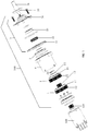
- the gear driving device of the present invention comprises a motor 100 and a driver gearbox 200 connected to the motor 100, the driver gearbox 200 is configured to transform and transfer rotation of an output shaft of the motor 100 to an actuator such as a telescoping mechanism, which allows an automotive movable part connected therewith to extend and retract relative to the body of the automobile.
- the movable part may be in particular a running board or a tonneau cover.
- the driver gearbox 200 comprises several stages of planetary gear assemblies connected in series and a small tooth difference gear assembly.
- a first stage planetary gear assembly in the stages of planetary gear assemblies is to be connected with the motor; and the last stage planetary gear assembly in the stages of planetary gear assemblies is to be connected with the small tooth difference gear assembly.
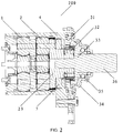
- the driver gearbox 200 comprises two stages of planetary gear assemblies, i.e. a first stage planetary gear assembly 1 and a second stage planetary gear assembly 2. Said two planetary gear assemblies 1 and 2 are connected to one another and installed in a cylindrical housing 4 of the driver gearbox 200, as shown in Fig. 2 .
- the first stage planetary gear assembly 1 comprises a disc shaped planetary carrier 11 and a plurality of gears 12 arranged on a side of the planetary carrier 11. These gears 12 are arranged at intervals in the circumferential or peripheral direction of the planetary carrier 11, and may come into engagement with a gear 101 fixed on an output shaft of the motor 100, so as to receive and transform or transfer rotation of the output shaft of the motor 100.
- the second stage planetary gear assembly 2 comprises a disc shaped planetary carrier 21 and a plurality of gears 22 arranged on a side of the planetary carrier 21. These gears 12 are arranged at intervals in the circumferential or peripheral direction of the planetary carrier 21, and may come into engagement with a output gear 13 fixed on the other side of the planetary carrier 11 of the first stage planetary gear assembly 1, so as to receive and transform or transfer rotation of the first stage planetary gear assembly 1.
- an output shaft 23 is disposed at the other side of the planetary carrier 21 of the second stage planetary gear assembly 2.
- the output shaft 23 has a through hole extending in the axial direction (i.e. left-right direction in Fig. 2 ) and being concentric with the planetary carrier 2.
- a free end of the output shaft 23 comprises an eccentric shaft section 24 offset relative to the centre of the planetary carrier 21.
- the eccentric shaft section 24 is used for direct connection with a small tooth difference gear assembly 3. This will be described in details in the following.
- the small tooth difference gear assembly 3 of the present invention comprises a fixed gear 31, a movable gear 33, and a planetary gear 32 engaged simultaneously to the fixed gear 31 and the movable gear 33.
- the fixed gear 31 and the movable gear 33 are gears with inner teeth, while the planetary gear 32 has outer teeth engaged with the inner teeth.
- said fixed gear 31 has 22 teeth; said movable gear 33 has 23 teeth; and said planetary gear 32 has 20 teeth.
- the fixed gear 31 of the small tooth difference gear assembly 3 is fixed to an axial end of a housing support 34 of the small tooth difference gear assembly 3, such that the planetary gear 32 is sandwiched between the fixed gear 31 and the movable gear 33 installed near the other axial end of the housing support 34.
- the movable gear 33 and the planetary gear 32 are thus received within the housing support 34.
- the planetary gear 32 is directly fit on the eccentric shaft section 24 of the output shaft 23 of the second stage planetary gear assembly 2 via a bearing. In this way, the small tooth difference gear assembly 3 and the first and second stages planetary gear assemblies 1 and 2 are assembled to form a movement transmission mechanism between the motor 100 and a subsequent actuator.
- the movable gear 33 has, at its side away from the planetary gear 32, a shaft 36 extending from the housing support 34 as an output shaft of the entire gear driving device. As shown in the figure, the movable gear 33 is supported on the housing support 34 through an installing bearing 35 disposed on the shaft 36 and located within the housing support 34.
- the installing bearing 35 is a ball bearing.
- said installing bearing 35 is a composite bearing.
- the composite bearing is usually made of Teflon and bronze powder by winding and rolling, and has the advantage of large bearing capacity.
- a liner 5 is arranged between the small tooth difference gear assembly 3 and the second stage planetary gear assembly 2 directly associated with the assembly 3.
- the liner 5 may be installed on the output shaft 23 of the second stage planetary gear assembly 2, and may, at its two axial sides, respectively bear against the planetary carrier 21 of the second stage planetary gear assembly 2 and an end cover or projection of a housing 4.
- said liner 5 may fix the positions of the planetary gear assemblies 1 and 2 in the axial direction, preventing these assemblies 1, 2 from swinging and displacing, so as to reduce friction and lengthen the service life of the components.
- the liner 5 may be in the form of an oil bearing.
- the oil bearing may be made by powder metallurgy method as usual.
- the driver gearbox 200 of the present invention may be made of metal material or plastic material. This means that each component of said first and second gear assemblies 1 and 2 as well as said small tooth difference gear assembly 3 may be of metal or plastic.
- the motor 100 is preferably an electric motor.
Landscapes
- Engineering & Computer Science (AREA)
- General Engineering & Computer Science (AREA)
- Mechanical Engineering (AREA)
- Power Engineering (AREA)
- Retarders (AREA)
Applications Claiming Priority (2)
| Application Number | Priority Date | Filing Date | Title |
|---|---|---|---|
| CN201621092798.8U CN206060455U (zh) | 2016-09-29 | 2016-09-29 | 用于汽车的活动部件的齿轮驱动装置 |
| PCT/CN2017/092460 WO2018059067A1 (zh) | 2016-09-29 | 2017-07-11 | 用于汽车的活动部件的齿轮驱动装置 |
Publications (2)
| Publication Number | Publication Date |
|---|---|
| EP3522342A1 true EP3522342A1 (de) | 2019-08-07 |
| EP3522342A4 EP3522342A4 (de) | 2020-05-13 |
Family
ID=58367089
Family Applications (1)
| Application Number | Title | Priority Date | Filing Date |
|---|---|---|---|
| EP17854521.6A Withdrawn EP3522342A4 (de) | 2016-09-29 | 2017-07-11 | Getriebeantriebsvorrichtung für bewegliche teile in kraftfahrzeugen |
Country Status (4)
| Country | Link |
|---|---|
| US (1) | US20210332871A1 (de) |
| EP (1) | EP3522342A4 (de) |
| CN (1) | CN206060455U (de) |
| WO (1) | WO2018059067A1 (de) |
Cited By (1)
| Publication number | Priority date | Publication date | Assignee | Title |
|---|---|---|---|---|
| CN110033692A (zh) * | 2019-04-28 | 2019-07-19 | 重庆理工大学 | 一种行星齿轮机构运动教学装置 |
Families Citing this family (1)
| Publication number | Priority date | Publication date | Assignee | Title |
|---|---|---|---|---|
| CN206060455U (zh) * | 2016-09-29 | 2017-03-29 | 广东肇庆爱龙威机电有限公司 | 用于汽车的活动部件的齿轮驱动装置 |
Family Cites Families (9)
| Publication number | Priority date | Publication date | Assignee | Title |
|---|---|---|---|---|
| US3129611A (en) * | 1960-10-14 | 1964-04-21 | Lee Engineering Company | Speed reducers |
| JPH02154835A (ja) * | 1988-12-02 | 1990-06-14 | Komatsu Ltd | 小歯数差差動遊星歯車機構 |
| DE202006006116U1 (de) * | 2006-04-15 | 2006-06-14 | Festo Ag & Co. | Getriebeanordnung |
| CN102350514A (zh) * | 2011-09-03 | 2012-02-15 | 陈旭 | 液压马达驱动的行星齿轮传动式电动卡盘 |
| JP6139861B2 (ja) * | 2011-11-18 | 2017-05-31 | マグナ インターナショナル インコーポレイテッド | 自動ステップボード用ロッカーモール取付システム |
| JP6458923B2 (ja) * | 2014-05-14 | 2019-01-30 | 三井金属アクト株式会社 | ドア開閉装置 |
| JP6533647B2 (ja) * | 2014-06-30 | 2019-06-19 | 日本電産コパル株式会社 | ギアドモータ |
| CN104121337A (zh) * | 2014-07-10 | 2014-10-29 | 南京高精船用设备有限公司 | 自升式海洋平台少齿差行星结构升降齿轮箱 |
| CN206060455U (zh) * | 2016-09-29 | 2017-03-29 | 广东肇庆爱龙威机电有限公司 | 用于汽车的活动部件的齿轮驱动装置 |
-
2016
- 2016-09-29 CN CN201621092798.8U patent/CN206060455U/zh active Active
-
2017
- 2017-07-11 EP EP17854521.6A patent/EP3522342A4/de not_active Withdrawn
- 2017-07-11 US US16/336,828 patent/US20210332871A1/en not_active Abandoned
- 2017-07-11 WO PCT/CN2017/092460 patent/WO2018059067A1/zh unknown
Cited By (1)
| Publication number | Priority date | Publication date | Assignee | Title |
|---|---|---|---|---|
| CN110033692A (zh) * | 2019-04-28 | 2019-07-19 | 重庆理工大学 | 一种行星齿轮机构运动教学装置 |
Also Published As
| Publication number | Publication date |
|---|---|
| CN206060455U (zh) | 2017-03-29 |
| WO2018059067A1 (zh) | 2018-04-05 |
| US20210332871A1 (en) | 2021-10-28 |
| EP3522342A4 (de) | 2020-05-13 |
Similar Documents
| Publication | Publication Date | Title |
|---|---|---|
| US8307960B2 (en) | Single-part carrier for an electric parking brake actuator with planetary gear set | |
| US20130270047A1 (en) | Electric parking brake | |
| US9989113B2 (en) | Electronic parking brake | |
| WO2012065784A1 (de) | Elektromechanisch betätigbare fahrzeugbremse mit verbessertem kolben | |
| DE102012217275A1 (de) | Scheibenbremsvorrichtung | |
| EP0237743B1 (de) | Radial-Axial-Gleitlager, insbesondere für Automatik-Getriebe von Kraftfahrzeugen | |
| EP3004679B1 (de) | Elektrisch betätigbare trommelbremse | |
| CN101310087A (zh) | 用于机动车驱动装置的传动单元 | |
| US20180202517A1 (en) | Actuator Assembly For Electronic Parking Brake | |
| US9885413B2 (en) | Sliding sleeve for supporting sun gears | |
| EP3522342A1 (de) | Getriebeantriebsvorrichtung für bewegliche teile in kraftfahrzeugen | |
| DE112015004998T5 (de) | Elektromotorisch angetriebener Verstärker | |
| EP3222881A1 (de) | Elektrisches lineares stellglied und elektrische bremsvorrichtung | |
| EP3564557B1 (de) | Elektrischer aktuator | |
| US5147255A (en) | Spur gear transmission, in particular for a drive unit of an industrial truck | |
| US20220063579A1 (en) | Reduction gearbox for drum brake, offering significant conformability | |
| EP1664470B1 (de) | Antriebssystem für verstelleinrichtungen in kraftfahrzeugen | |
| CN110173542B (zh) | 支承螺旋行星齿轮的螺旋齿轮轴的轴承组件和其制造方法 | |
| US8235858B1 (en) | Gear drive | |
| EP3816476A1 (de) | Planetenträgeranordnung für schliessbetätiger einer kraftfahrzeugtür | |
| DE10361296A1 (de) | Selbstverstärkende elektromechanische Fahrzeugbremse | |
| US8894539B2 (en) | Wheel driving speed reducer | |
| CN111565985B (zh) | 齿轮传动马达及其齿轮组件、用于机动车辆的驻车制动系统及行车制动系统 | |
| KR102488782B1 (ko) | 기어박스 및 이를 포함하는 액츄에이터 | |
| CN115335613A (zh) | 用于制动装备的制动力发生器、用于制动装备的操纵装置 |
Legal Events
| Date | Code | Title | Description |
|---|---|---|---|
| PUAI | Public reference made under article 153(3) epc to a published international application that has entered the european phase |
Free format text: ORIGINAL CODE: 0009012 |
|
| 17P | Request for examination filed |
Effective date: 20190326 |
|
| AK | Designated contracting states |
Kind code of ref document: A1 Designated state(s): AL AT BE BG CH CY CZ DE DK EE ES FI FR GB GR HR HU IE IS IT LI LT LU LV MC MK MT NL NO PL PT RO RS SE SI SK SM TR |
|
| AX | Request for extension of the european patent |
Extension state: BA ME |
|
| DAV | Request for validation of the european patent (deleted) | ||
| DAX | Request for extension of the european patent (deleted) | ||
| A4 | Supplementary search report drawn up and despatched |
Effective date: 20200417 |
|
| RIC1 | Information provided on ipc code assigned before grant |
Ipc: F16H 1/46 20060101ALI20200409BHEP Ipc: F16H 1/32 20060101ALN20200409BHEP Ipc: H02K 7/116 20060101AFI20200409BHEP Ipc: B60R 3/02 20060101ALN20200409BHEP |
|
| STAA | Information on the status of an ep patent application or granted ep patent |
Free format text: STATUS: THE APPLICATION HAS BEEN WITHDRAWN |
|
| 18W | Application withdrawn |
Effective date: 20201015 |