EP3522301B1 - Verbindungvorrichtung und energieversorgungsanordnung - Google Patents
Verbindungvorrichtung und energieversorgungsanordnung Download PDFInfo
- Publication number
- EP3522301B1 EP3522301B1 EP18209419.3A EP18209419A EP3522301B1 EP 3522301 B1 EP3522301 B1 EP 3522301B1 EP 18209419 A EP18209419 A EP 18209419A EP 3522301 B1 EP3522301 B1 EP 3522301B1
- Authority
- EP
- European Patent Office
- Prior art keywords
- connector
- fastening screw
- connecting apparatus
- latching
- section
- Prior art date
- Legal status (The legal status is an assumption and is not a legal conclusion. Google has not performed a legal analysis and makes no representation as to the accuracy of the status listed.)
- Active
Links
Images
Classifications
-
- H—ELECTRICITY
- H01—ELECTRIC ELEMENTS
- H01R—ELECTRICALLY-CONDUCTIVE CONNECTIONS; STRUCTURAL ASSOCIATIONS OF A PLURALITY OF MUTUALLY-INSULATED ELECTRICAL CONNECTING ELEMENTS; COUPLING DEVICES; CURRENT COLLECTORS
- H01R4/00—Electrically-conductive connections between two or more conductive members in direct contact, i.e. touching one another; Means for effecting or maintaining such contact; Electrically-conductive connections having two or more spaced connecting locations for conductors and using contact members penetrating insulation
- H01R4/28—Clamped connections, spring connections
- H01R4/30—Clamped connections, spring connections utilising a screw or nut clamping member
- H01R4/302—Clamped connections, spring connections utilising a screw or nut clamping member having means for preventing loosening of screw or nut, e.g. vibration-proof connection
-
- H—ELECTRICITY
- H01—ELECTRIC ELEMENTS
- H01R—ELECTRICALLY-CONDUCTIVE CONNECTIONS; STRUCTURAL ASSOCIATIONS OF A PLURALITY OF MUTUALLY-INSULATED ELECTRICAL CONNECTING ELEMENTS; COUPLING DEVICES; CURRENT COLLECTORS
- H01R13/00—Details of coupling devices of the kinds covered by groups H01R12/70 or H01R24/00 - H01R33/00
- H01R13/62—Means for facilitating engagement or disengagement of coupling parts or for holding them in engagement
- H01R13/621—Bolt, set screw or screw clamp
-
- H—ELECTRICITY
- H01—ELECTRIC ELEMENTS
- H01M—PROCESSES OR MEANS, e.g. BATTERIES, FOR THE DIRECT CONVERSION OF CHEMICAL ENERGY INTO ELECTRICAL ENERGY
- H01M50/00—Constructional details or processes of manufacture of the non-active parts of electrochemical cells other than fuel cells, e.g. hybrid cells
- H01M50/50—Current conducting connections for cells or batteries
- H01M50/502—Interconnectors for connecting terminals of adjacent batteries; Interconnectors for connecting cells outside a battery casing
- H01M50/505—Interconnectors for connecting terminals of adjacent batteries; Interconnectors for connecting cells outside a battery casing comprising a single busbar
-
- H—ELECTRICITY
- H01—ELECTRIC ELEMENTS
- H01M—PROCESSES OR MEANS, e.g. BATTERIES, FOR THE DIRECT CONVERSION OF CHEMICAL ENERGY INTO ELECTRICAL ENERGY
- H01M50/00—Constructional details or processes of manufacture of the non-active parts of electrochemical cells other than fuel cells, e.g. hybrid cells
- H01M50/50—Current conducting connections for cells or batteries
- H01M50/502—Interconnectors for connecting terminals of adjacent batteries; Interconnectors for connecting cells outside a battery casing
- H01M50/514—Methods for interconnecting adjacent batteries or cells
- H01M50/517—Methods for interconnecting adjacent batteries or cells by fixing means, e.g. screws, rivets or bolts
-
- H—ELECTRICITY
- H01—ELECTRIC ELEMENTS
- H01M—PROCESSES OR MEANS, e.g. BATTERIES, FOR THE DIRECT CONVERSION OF CHEMICAL ENERGY INTO ELECTRICAL ENERGY
- H01M50/00—Constructional details or processes of manufacture of the non-active parts of electrochemical cells other than fuel cells, e.g. hybrid cells
- H01M50/50—Current conducting connections for cells or batteries
- H01M50/572—Means for preventing undesired use or discharge
- H01M50/584—Means for preventing undesired use or discharge for preventing incorrect connections inside or outside the batteries
- H01M50/588—Means for preventing undesired use or discharge for preventing incorrect connections inside or outside the batteries outside the batteries, e.g. incorrect connections of terminals or busbars
-
- H—ELECTRICITY
- H01—ELECTRIC ELEMENTS
- H01M—PROCESSES OR MEANS, e.g. BATTERIES, FOR THE DIRECT CONVERSION OF CHEMICAL ENERGY INTO ELECTRICAL ENERGY
- H01M50/00—Constructional details or processes of manufacture of the non-active parts of electrochemical cells other than fuel cells, e.g. hybrid cells
- H01M50/50—Current conducting connections for cells or batteries
- H01M50/572—Means for preventing undesired use or discharge
- H01M50/584—Means for preventing undesired use or discharge for preventing incorrect connections inside or outside the batteries
- H01M50/59—Means for preventing undesired use or discharge for preventing incorrect connections inside or outside the batteries characterised by the protection means
- H01M50/591—Covers
-
- H—ELECTRICITY
- H01—ELECTRIC ELEMENTS
- H01R—ELECTRICALLY-CONDUCTIVE CONNECTIONS; STRUCTURAL ASSOCIATIONS OF A PLURALITY OF MUTUALLY-INSULATED ELECTRICAL CONNECTING ELEMENTS; COUPLING DEVICES; CURRENT COLLECTORS
- H01R4/00—Electrically-conductive connections between two or more conductive members in direct contact, i.e. touching one another; Means for effecting or maintaining such contact; Electrically-conductive connections having two or more spaced connecting locations for conductors and using contact members penetrating insulation
- H01R4/70—Insulation of connections
-
- H—ELECTRICITY
- H01—ELECTRIC ELEMENTS
- H01R—ELECTRICALLY-CONDUCTIVE CONNECTIONS; STRUCTURAL ASSOCIATIONS OF A PLURALITY OF MUTUALLY-INSULATED ELECTRICAL CONNECTING ELEMENTS; COUPLING DEVICES; CURRENT COLLECTORS
- H01R11/00—Individual connecting elements providing two or more spaced connecting locations for conductive members which are, or may be, thereby interconnected, e.g. end pieces for wires or cables supported by the wire or cable and having means for facilitating electrical connection to some other wire, terminal, or conductive member, blocks of binding posts
- H01R11/11—End pieces or tapping pieces for wires, supported by the wire and for facilitating electrical connection to some other wire, terminal or conductive member
- H01R11/28—End pieces consisting of a ferrule or sleeve
- H01R11/281—End pieces consisting of a ferrule or sleeve for connections to batteries
- H01R11/288—Interconnections between batteries
-
- H—ELECTRICITY
- H01—ELECTRIC ELEMENTS
- H01R—ELECTRICALLY-CONDUCTIVE CONNECTIONS; STRUCTURAL ASSOCIATIONS OF A PLURALITY OF MUTUALLY-INSULATED ELECTRICAL CONNECTING ELEMENTS; COUPLING DEVICES; CURRENT COLLECTORS
- H01R2201/00—Connectors or connections adapted for particular applications
- H01R2201/26—Connectors or connections adapted for particular applications for vehicles
-
- H—ELECTRICITY
- H01—ELECTRIC ELEMENTS
- H01R—ELECTRICALLY-CONDUCTIVE CONNECTIONS; STRUCTURAL ASSOCIATIONS OF A PLURALITY OF MUTUALLY-INSULATED ELECTRICAL CONNECTING ELEMENTS; COUPLING DEVICES; CURRENT COLLECTORS
- H01R4/00—Electrically-conductive connections between two or more conductive members in direct contact, i.e. touching one another; Means for effecting or maintaining such contact; Electrically-conductive connections having two or more spaced connecting locations for conductors and using contact members penetrating insulation
- H01R4/28—Clamped connections, spring connections
- H01R4/30—Clamped connections, spring connections utilising a screw or nut clamping member
- H01R4/305—Clamped connections, spring connections utilising a screw or nut clamping member having means for facilitating engagement of conductive member or for holding it in position
Definitions
- the invention relates to a connecting device for electrically connecting at least two electrical connections to one another, with an electrically conductive connector which has at least one through opening for receiving a screw shaft of a fastening screw, with at least one electrically non-conductive and in particular multi-part connector cover for receiving the connector in a protected manner and with at least one electrically conductive fastening screw which can be screwed into a mating thread of one of the connections.
- the invention also relates to a power supply arrangement which has the above-mentioned connection device and at least one electrical connection.
- a connecting device of the type mentioned is already known.
- a connecting device which has at least one contact-protected electrical connector.
- the connector is arranged or can be arranged in a multi-part connector cover, which itself is electrically non-conductive or electrically insulating, so that when the connection device is used, people are protected from the electrical voltage or from an electrical current flowing through the connector. Particularly during assembly, this ensures that the fitter assembling the connecting device is not exposed to any danger whatsoever.
- the fastening screw itself is provided with an electrically insulating protective layer and is added by the fitter during the assembly of the individual parts.
- a connecting device with the features of the preamble of claim 1 is, for example, from the laid-open specification DE 10 2013 005 092 A1 known. Further connecting devices are from the publications EP 2 063 492 A2 , US 2012/0108107 A1 , DE 10 2014 012 320 B3 as well as from the Offenlegungsschrift US 2014/0322994 A1 known.
- the invention is based on the object of creating an improved connecting device which simplifies assembly while maintaining a high or improved level of safety.
- the object on which the invention is based is achieved by a connecting device having the features of claim 1.
- This has the advantage that the fitter can position the fastening screw before he feeds the connecting device to the connections, so that he preassembles the fastening screw in a state in which the connections of the system to be connected are not yet electrically contacted.
- the connector cover has a device for releasably holding the at least one fastening screw in a pre-assembly position.
- the fastening screw can therefore be transported with the connecting device in a pre-assembly position, so that the fitter only has to move the fastening screw from the pre-assembly position into the assembly position, in particular screw, to make the actual contacting of the connections.
- a supply to the connections in such a way that the connector also makes electrical contact, in particular touches or is mechanically tensioned / clamped, is thereby ensured in a simple manner.
- the releasable holding in the pre-assembly position enables final assembly of the fastening screw in particular, in which the user does not have to make any physical contact with the fastening screw and / or the connector, apart from connecting a tool to the fastening screw for applying a torque to the fastening screw.
- the tool is preferably also designed to be electrically insulating and / or the fastening screw has electrical insulation at a tool holder or coupling point, as disclosed, for example, in the aforementioned publication, so that no electrical contact is made even if the fastening screw is in mechanical contact.
- the device has one or more elastically and / or plastically deformable latching tongues, each latching tongue having a retaining lug on which the screw head rests or can be placed in the pre-assembly position and which can be disengaged from the screw head by the deformation.
- the fastening screw can thus be set down on the retaining lugs during preassembly, so that it is in particular at a distance from the connections when the connection device is installed on the connections.
- the fastening screw is arranged withdrawn in particular in the connector cover in such a way that it does not pierce the cover.
- the deformability of the locking tongues ensures that the retaining lugs can be brought out of engagement with the screw head.
- the fastening screw can be moved further and brought into engagement with the connections.
- the locking tongues with the retaining lugs for example by a bevel, are designed such that when a predeterminable axial force is applied to the fastening screw, the retaining lugs are disengaged from the screw head by deforming the locking tongues. This ensures easy assembly for the fitter.
- the device has at least two locking tongues arranged opposite one another.
- the fastening screw is held securely from two sides by the locking lugs in the pre-assembly position, which prevents the fastening screw from tilting, for example.
- the device particularly preferably has at least four locking tongues, two of which are opposite each other, so that the fastening screw is securely held at its screw head at four points in the pre-assembly position.
- the device has exactly three locking tongues which are arranged distributed evenly over the circumference of the fastening screw, that is to say are each arranged at an angle of 120 degrees to one another.
- the locking tongues preferably extend at least in sections parallel to the screw shank of the fastening screw in the pre-assembly position, being attached to an end remote from the screw head and each having the locking lug on their end facing the screw head.
- the latching tongues offer a long lever, by means of which the latching lugs can be moved outward or away from the screw shaft by elastic and / or plastic deformations of the respective latching tongue in order to disengage from the screw head.
- the connector cover has a lower part on which the at least one connector can be arranged, and an upper part which can be arranged on the lower part including the connector, and wherein the locking tongues are arranged on the lower part of the connector cover and are in Extend towards the top.
- the latching tongues are preferably designed in such a way that their latching lugs rest against the screw shaft of the fastening screw under prestress when the Fastening screw is in the pre-assembly position.
- the locking lugs are preferably so close to one another that the distance between them is smaller than the diameter of the screw head.
- the locking tongues are assigned to an opening in the lower part through which the fastening screw can be axially displaced in the direction of the connector and / or the connections, so that the fastening lugs hold the fastening screw in the correct position for the subsequent fastening and contacting process.
- the upper part has a cup-shaped receiving dome for the fastening screw and the locking tongues of the device associated with the fastening screw.
- the fastening dome thus protrudes from the rest of the upper part and can be easily and reliably found by the fitter, so that the assembly process can be carried out quickly and safely by the fitter.
- the fastening screw and the locking tongues are securely protected in the receiving dome.
- the receiving dome has a recess in the dome base, through which a screwing tool can be inserted for applying a tightening torque to the fastening screw located in the receiving dome.
- a screwing tool can be inserted for applying a tightening torque to the fastening screw located in the receiving dome.
- the lower part preferably has at least one first section on which the connector can be placed, and at least one second section which overlaps the connector placed on the first section on a side facing away from the first section, the locking tongues being formed or on the second section are arranged.
- the connector can thus be arranged on a lower part between the first and the second section.
- the connector can advantageously be positioned in the lower part, so that simple joining with the upper part is ensured.
- the fact that the connector is held in a form-fitting manner from two sides by the lower part, by the first section on one side and the second section on the other side, simplifies the pre-assembly.
- the fact that the locking tongues are formed or arranged on the second section ensures that the locking tongues protrude in the direction of the upper part and can be used for advantageous pre-positioning of the fastening screw in the pre-assembly position.
- the upper part can be or is fastened to the lower part by at least one latching.
- the latching ensures a simple joining process in which the upper part is attached to the lower part in a form-fitting manner.
- an elastic deformation of the upper part and / or the lower part occurs during joining, so that the upper part engages behind the lower part or the lower part positively engages the upper part at at least one point.
- the latching can be made detachable or non-detachable.
- the lower part has at least one latching tongue for locking the at least one connector between the first and the second section.
- the locking tongue ensures that the connector cannot be easily removed from the lower part, so that the connector is securely held in the lower part during the pre-assembly.
- the latching tongue is selected such that the connector, as soon as it has reached its end position in the lower part, is positively engaged behind by the latching tongue and is thereby held in the lower part.
- the lower part has a central first section and two eccentric second sections.
- the connector is thus securely stored in the lower part.
- the shape of the lower part in particular the distance between the sections, is adapted to the shape of the connector in such a way that the connector is held positively in the lower part, in particular with only small tolerances, so that rattling noises or the like are avoided.
- the first and the second section are arranged in such a way that their projected distance from one another is less than the height of the connector, so that when the connector is installed in the lower part, the lower part is elastically deformed and exerts a pretensioning force on the connector, whereby Rattling noises can be safely avoided during later operation, even if major vibrations occur.
- the connecting device has at least two fastening screws which, as described above, can be arranged on the connector cover in a respective pre-assembly position.
- a device is assigned to each fastening screw, as described above.
- there is a fastening screw for each connection in order to establish the electrical connection through the connector by joining the fastening screws to the connections. This ensures simple joining of the connecting device to the connections or to a system having the connections.
- the connecting device has at least two superposed / stacked connector elements, whereby the maximum possible current flow through the connecting device is increased and can be adapted by adding or removing connecting elements.
- the respective connector is designed as a busbar.
- known technologies can be used, which reduces manufacturing costs.
- the respective connector for each of the fastening screws an opening for receiving or for carrying out the respective screw shaft in order to ensure simple assembly.
- the energy storage arrangement according to the invention with the features of claim 15 is characterized by at least one connecting device according to the invention. This results in the advantages already mentioned.
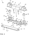
- Figure 1 shows, in a perspective exploded view, an advantageous connector device 1 for electrical high-voltage devices, such as, for example, energy storage devices for motor vehicles, in particular traction batteries.
- the present device 1 is used, for example, to electrically connect the connections of two battery cells to one another.
- the connecting device 1 has an electrical connector 2, which can be arranged so as to be protected against contact by a multi-part connector cover 3.
- the connector cover 3 has an upper part 4 and a lower part 5, between which the connector 2 can be arranged.
- the connector 2 has two connector elements 2_1 and 2_2 which are stacked on top of one another and which are of the same shape and lie flat on top of one another.
- the maximum electrical conductivity of the connector 2 can be expanded by adding further connector elements.
- the connector elements 2_1, 2_2 are plate-shaped in the form of busbars and each have two through openings 6, the through openings 6 being assigned to the respective end of the connector elements 2_1, 2_2 or the connector 2.
- the lower part 5 has a central first section 7 on which the connector 2 can be placed.
- the middle section 7 is connected in one piece to two outer second sections 9 by a rear wall 8.
- the second sections 9 are above the middle one Section 7, so that the connector 2 can be inserted or pushed in laterally between the middle section 7 and the second section 9, as indicated by an arrow 10.
- the connector 2 can be pushed in as far as the rear wall 8.
- the middle section 7 also has an elastically deformable latching tongue 11 which engages behind the connector 2 when the connector is completely pushed into the lower part 5.
- the latching tongue 11 has an insertion bevel, through which the latching tongue 11 is elastically displaced when the connector 2 is inserted.
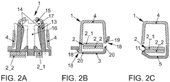
- Figure 2C shows a section through the preassembled connector device 1 along the line CC Figure 1 in the preassembled state, when the connector 2 with the two connector elements 2_1 and 2_2 is inserted between the sections 7 and 9 and the latching tongue 11 engages behind it in a form-fitting manner.
- the side sections 9 each have an opening 12, on the edge of which four latching tongues 13 are arranged, two of the latching tongues 13 being opposite one another.
- the locking tongues 13 protrude from the section 9, specifically in the direction of the side of the section 9 facing away from the central section 7, and each have a locking lug 14 at their free ends.
- the locking lugs 14 are formed in this case by inclined end faces of the locking tongues 13. In the unloaded state, the latching lugs 14 or latching tongues 13 are so close together that a fastening screw 15 with its screw shaft 16 can only be inserted between the latching lugs 14 in the direction of the central section 9 with elastic displacement of the latching lugs 14.
- the locking lugs 14 are arranged so close together that they are pushed slightly outward when the screw shaft 16 is inserted, so that a pretensioning force is exerted on the screw shaft 16 by the locking tongues 13, whereby the fastening screw 15 is advantageously aligned.
- the screw 15 can be inserted up to its screw head 17 between the locking tongues 13 in the direction of the opening 12. As soon as the screw head 17 comes to rest on the locking lugs 14, the fastening screw 15 can only be pushed through with increased force. The fastening screw 15 is thus held in a pre-assembly position by the locking tongues 13 when the screw head 17 rests on the locking lugs 14.
- Figure 2A shows a first sectional view through the connecting device 1 when the connector 2 is inserted and the upper part 4 is connected to the lower part 5 and the fastening screws 15 are brought into their pre-assembly position.
- FIG. 2B shows a Sectional view through the connector device 1 along the line B_B Figure 1 in the pre-assembled state when the latches 18 are made
- FIG 2A shows a section through the connector device 1 along the line A_A Figure 1 , wherein the fastening screw 15 is in its pre-assembly position (dashed line).
- the upper part 4 has a receiving dome 21 for the respective fastening screw 15 and the associated latching tongues 13, the receiving dome 21 having several openings 22 in its jacket wall through which the latching tongues 13 can already penetrate with their free ends.
- the openings 22 allow the latching tongues 13 to be pushed outward when the fastening screw 15 is subjected to an increased axial force, which acts on the latching lugs 14 in such a way that the latching tongues 13 are bent radially outward and thus out of engagement with the screw head 17 (dashed lines in Figure 2A ). If a sufficient axial force is applied to the fastening screw 15, the holder of the fastening screw 15 is released.
- the holding tongues 13 thus each form a device 23 for the fastening screw 15 for releasably holding the fastening screw in a pre-assembly position.
- the screw 15 with the screw head 17 can be pushed through the opening 2 up to the connector 2, the openings 6 and 12 being designed or arranged in such a way that the fastening screw with the screw shaft 16 directly through the respective opening 6 of the Connection 2 is passed through. If the respective fastening screw 15 is now subjected to a tightening torque and screwed into a mating thread of the respective associated electrical connection of the electrical system, the connection device 1 is simply and securely attached to the connection or to the respective connection and the electrical connection through the connector 2 between the both connections made.
- the fact that the connector 2 is essentially housed in the connector cover 3 ensures advantageous contact protection for the user and in particular the fitter during the assembly of the connector device 1.
- the advantageous pre-assembly of the respective fastening screw 15 also ensures a particularly simple and safe final assembly.
- the screw head 17 is preferably provided with an electrically insulating coating or made of an electrically insulating material, so that a particularly high level of electrical protection for the user is guaranteed.
- the different latches enable simple assembly and pre-assembly of the connector device 1.
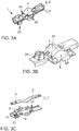
- FIGS 3A to 3C show a further exemplary embodiment of the connector device 1, elements already known from the previous exemplary embodiment being provided with the same reference numerals and in this respect reference is made to the description above. In the following, the differences will essentially be discussed.
- the main difference from the previous exemplary embodiment lies in the device 23, by means of which one of the fastening screws 15 can be brought into a pre-assembly position.
- the pre-assembly position is based on the weight of the fastening screw, which can be inserted in a receiving dome 21 of the upper part 4.
- the fastening screw 15 with the screw head 17 is first inserted into the receiving dome 21 from the side facing the lower part 5, so that the threaded shaft or screw shaft 16 protrudes in the direction of the lower part.
- the connector 2 is then placed in place in such a way that the screw shaft 16 reaches one of the recesses 6.
- the lower part 5 is then placed on top and connected to the upper part 4 by means of a latch 18.
- the connector also has two connector elements 2_1 and 2_2, which differ from the preceding connector parts 2_1 and 2_2 in that they have a bulge in the middle, the bulges facing each other so that a spring tension between the connectors 2_1 and 2_2 arises in the assembled state, which securely maintains the latching 18 permanently.
- the upper part 4 and lower part 5 are connected to one another by a film hinge 24.
- a film hinge 24 This results in particular in a one-piece design of the connector cover 3.
- the lower part 5 is pivoted around an axis of the film hinge 24 and latched to the upper part 4 at its free end.
- a corresponding film hinge 24 can also be used in the exemplary embodiment from FIG Figures 1 to 2 be provided.
Landscapes
- Chemical & Material Sciences (AREA)
- Chemical Kinetics & Catalysis (AREA)
- Electrochemistry (AREA)
- General Chemical & Material Sciences (AREA)
- Connector Housings Or Holding Contact Members (AREA)
- Details Of Connecting Devices For Male And Female Coupling (AREA)
- Battery Mounting, Suspending (AREA)
Description
- Die Erfindung betrifft eine Verbindungsvorrichtung zum elektrischen Verbinden von zumindest zwei elektrischen Anschlüssen miteinander, mit einem elektrisch leitfähigen Verbinder, der zumindest eine Durchgangsöffnung zur Aufnahme eines Schraubenschafts einer Befestigungsschraube aufweist, mit zumindest einer elektrisch nicht-leitfähigen und insbesondere mehrteilig ausgebildeten Verbinderabdeckung zur berührungsgeschützten Aufnahme des Verbinders und mit zumindest einer elektrisch leitfähigen Befestigungsschraube, die in ein Gegengewinde eines der Anschlüsse einschraubbar ist.
- Weiterhin betrifft die Erfindung eine Energieversorgungsanordnung, die die oben genannte Verbindungsvorrichtung und zumindest einen elektrischen Anschluss aufweist.
- Aus der Offenlegungsschrift
DE 10 2016 200 451 A1 ist bereits eine Verbindungsvorrichtung der Eingangs genannten Art bekannt. Zum Anschluss von Hochvoltspeichern und/oder Hochvoltverbrauchern ist es bekannt, diese durch eine Verbindungsvorrichtung elektrisch zu kontaktieren oder miteinander zu verbinden, welche zumindest einen berührungsgeschützten elektrischen Verbinder aufweist. Der Verbinder ist in einer mehrteiligen Verbinderabdeckung, die selbst elektrisch nicht-leitfähig beziehungsweise elektrisch isolierend ausgebildet ist, angeordnet beziehungsweise anordenbar, so dass bei der Verwendung der Verbindungsvorrichtung Personen vor der elektrischen Spannung beziehungsweise vor einem durch den Verbinder fließenden elektrischen Strom geschützt sind. Insbesondere auch bei der Montage wird hierdurch erreicht, dass der die Verbindungsvorrichtung montierende Monteur keinerlei Gefahr ausgesetzt ist. In der oben genannten Offenlegungsschrift ist dabei vorgesehen, dass die Befestigungsschraube selbst mit einer elektrisch isolierenden Schutzschicht versehen ist, und während der Montage der Einzelteile vom Monteur hinzugefügt wird. - Eine Verbindungsvorrichtung mit den Merkmalen des Oberbegriffs des Anspruchs 1 ist beispielsweise aus der Offenlegungsschrift
DE 10 2013 005 092 A1 bekannt. Weitere Verbindungsvorrichtungen sind aus den DruckschriftenEP 2 063 492 A2 ,US 2012/0108107 A1 ,DE 10 2014 012 320 B3 sowie aus der OffenlegungsschriftUS 2014/0322994 A1 bekannt. Der Erfindung liegt die Aufgabe zugrunde, eine verbesserte Verbindungsvorrichtung zu schaffen, welche die Montage bei gleichbleibend hoher oder verbesserter Sicherheit vereinfacht. - Die der Erfindung zugrunde liegende Aufgabe wird durch eine Verbindungsvorrichtung mit den Merkmalen des Anspruchs 1 gelöst. Diese hat den Vorteil, dass der Monteur die Befestigungsschraube bereits positionieren kann, bevor er die Verbindungsvorrichtung den Anschlüssen zuführt, so dass er die Befestigungsschraube in einem Zustand vormontiert, in welchem die Anschlüsse der zu verbindenden Anlage noch nicht elektrisch kontaktiert sind. Erfindungsgemäß wird dadurch erreicht, dass die Verbinderabdeckung eine Einrichtung zum lösbaren Halten der zumindest einen Befestigungsschraube in einer Vormontagestellung aufweist. Die Befestigungsschraube ist somit mit der Verbindungsvorrichtung mit transportierbar in einer Vormontagestellung haltbar, so dass der Monteur zur Durchführung der eigentlichen Kontaktierung der Anschlüsse nur noch die Befestigungsschraube aus der Vormontagestellung in die Montagestellung bewegen, insbesondere schrauben muss. Ein Zuführen zu den Anschlüssen derart, dass der Verbinder dabei mit elektrisch kontaktiert, insbesondere berührt oder mechanisch verspannt/eingeklemmt wird, ist dadurch in einfacher Art und Weise gewährleistet. Durch das lösbare Halten in der Vormontagestellung ist insbesondere eine Endmontage der Befestigungsschraube möglich, bei welcher der Benutzer keinerlei Berührungskontakt mit der Befestigungsschraube und/oder dem Verbinder eingehen muss, abgesehen von der Verbindung eines Werkzeugs mit der Befestigungsschraube zum Aufbringen eines Drehmoments auf die Befestigungsschraube. Dabei ist jedoch vorzugsweise auch das Werkzeug elektrisch isolierend ausgebildet und/oder die Befestigungsschraube weist an einer Werkzeugaufnahme oder Kopplungsstelle, wie beispielsweise in der zuvor genannten Druckschrift offenbart, eine elektrische Isolierung auf, so dass auch bei einem mechanischen Berührungskontakt der Befestigungsschraube keine elektrische Kontaktierung erfolgt.
- Erfindungsgemäß weist die Einrichtung eine oder mehrere elastisch und/oder plastisch verformbare Rastzungen auf, wobei jede Rastzunge eine Haltenase aufweist, auf welcher der Schraubenkopf in der Vormontagestellung aufliegt oder auflegbar ist, und die durch die Verformung außer Eingriff mit dem Schraubenkopf bringbar ist. Die Befestigungsschraube ist somit bei der Vormontage auf den Haltenasen absetzbar, so dass sie insbesondere beabstandet von den Anschlüssen bei der Montage der Verbindungvorrichtung an den Anschlüssen liegt. Dazu ist die Befestigungsschraube insbesondere in der Verbinderabdeckung derart zurückgezogen angeordnet, dass sie die Abdeckung nicht durchstößt. Durch die Verformbarkeit der Rastzungen ist gewährleistet, dass die Haltenasen außer Eingriff mit dem Schraubenkopf bringbar sind. Sobald dies geschieht, ist die Befestigungsschraube weiter bewegbar und in Eingriff mit den Anschlüssen bringbar. Hierdurch ist eine einfache Vormontagestellung sowie eine einfache Verbringung der Befestigungsschraube in eine Endmontageposition sicher gewährleistet. Insbesondere sind die Rastzungen mit den Haltenasen, beispielsweise durch eine Anlaufschräge, derart ausgebildet, dass bei Aufbringen einer vorgebbaren Axialkraft auf die Befestigungsschraube die Haltenasen durch Verformen der Rastzungen außer Eingriff mit dem Schraubenkopf gebracht werden. Dadurch ist eine einfache Montage für den Monteur gewährleistet.
- Weiterhin ist bevorzugt vorgesehen, dass die Einrichtung zumindest zwei einander gegenüberliegend angeordnete Rastzungen aufweist. Dadurch ist die Befestigungsschraube in der Vormontagestellung sicher von zwei Seiten durch die Rastnasen gehalten, wodurch beispielsweise ein Verkippen der Befestigungsschraube vermieden wird. Besonders bevorzugt weist die Einrichtung zumindest vier Rastzungen auf, von denen sich jeweils zwei gegenüber liegen, so dass die Befestigungsschraube in der Vormontagestellung an ihrem Schraubenkopf an vier Stellen sicher gehalten ist. Gemäß einer weiteren Ausführungsform ist bevorzugt vorgesehen, dass die Einrichtung genau drei Rastzungen aufweist, die gleichmäßig über den Umfang der Befestigungsschraube verteilt angeordnet sind, also jeweils in einem Winkel von 120 Grad zueinander angeordnet sind. Bevorzugt erstrecken sich die Rastzungen zumindest abschnittsweise parallel zu dem Schraubenschaft der Befestigungsschraube in der Vormontagestellung, wobei sie an einem von dem Schraubenkopf entfernten Ende befestigt sind und an ihrem dem Schraubenkopf zugewandten Ende jeweils die Rastnase aufweisen. Dadurch bieten die Rastzungen einen langen Hebel, durch welchen die Rastnasen durch elastische und/oder plastische Verformungen der jeweiligen Rastzunge nach außen beziehungsweise von dem Schraubenschaft weg bewegbar sind, um außer Eingriff mit dem Schraubenkopf zu geraten.
- Erfindungsgemäß ist vorgesehen, dass die Verbinderabdeckung ein Unterteil, an welchem der zumindest eine Verbinder anordenbar ist, und ein Oberteil, welches an dem Unterteil unter Einschließen des Verbinders anordenbar ist, aufweist, und wobei die Rastzungen an dem Unterteil der Verbinderabdeckung angeordnet sind und sich in Richtung des Oberteils erstrecken. Hierdurch wird durch die Verbinderabdeckung ein kompaktes Gehäuse gebildet, welches einen Berührungsschutz für den darin angeordneten Verbinder bietet. Dadurch, dass sich die Rastzungen in Richtung des Oberteils erstrecken, sind sie insbesondere auch in dem Oberteil geschützt liegend angeordnet, so dass ein versehentliches Lösen der Befestigungsschraube aus der Halte-Einrichtung vermieden ist. Dadurch ist eine Fehlbenutzung der Verbindungsvorrichtung sicher vermieden.
- Weiterhin sind die Rastzungen bevorzugt derart ausgebildet, dass sie mit ihren Rastnasen unter Vorspannung an dem Schraubenschaft der Befestigungsschraube anliegen, wenn sich die Befestigungsschraube in der Vormontagestellung befindet. Hierdurch ergibt sich der Vorteil, dass die Rastnasen die Befestigungsschraube nicht nur axial, sondern auch radial stützen, wodurch insbesondere die Ausrichtung der Befestigungsschraube in der Vormontagestellung gesichert ist. In ihrer Ausgangsstellung liegen die Rastnasen dazu bevorzugt derart nah beieinander, dass der Abstand zwischen ihnen kleiner ist als der Durchmesser des Schraubenkopfes. Insbesondere sind die Rastzungen einer Öffnung des Unterteils zugeordnet, durch welche die Befestigungsschraube in Richtung des Verbinders und/oder der Anschlüsse axial verlagerbar ist, so dass durch die Rastnasen die Befestigungsschraube bereits an der richtigen Position für den späteren Befestigungsvorgang und Kontaktiervorgang gehalten ist.
- Weiterhin weist das Oberteil erfindungsgemäß einen becherförmigen Aufnahmedom für die Befestigungsschraube und die der Befestigungsschraube zugeordneten Rastzungen der Einrichtung auf. Der Befestigungsdom steht somit von dem übrigen Oberteil vor, und ist von dem Monteur einfach und sicher auffindbar, so dass der Montagevorgang vom Monteur schnell und sicher durchführbar ist. In dem Aufnahmedom liegen die Befestigungsschraube und die Rastzungen sicher geschützt.
- Gemäß einer bevorzugten Weiterbildung der Erfindung weist der Aufnahmedom eine Aussparung im Domboden auf, durch welche ein Schraubwerkzeug zum Beaufschlagen der in dem Aufnahmedom liegenden Befestigungsschraube mit einem Anzugsdrehmoment einführbar ist. Dadurch ist der Verschraubungsvorgang der Befestigungsschraube einfach und sicher durchführbar. Darüber hinaus kann der Benutzer durch die Aussparung hindurch erkennen, ob eine Befestigungsschraube in der Verbindungvorrichtung beziehungsweise innerhalb der Verbinderabdeckung angeordnet wurde und sich in der Vormontagestellung befindet.
- Das Unterteil weist bevorzugt zumindest einen ersten Abschnitt auf, auf welchen der Verbinder auflegbar ist, und zumindest einen zweiten Abschnitt, welcher den auf den ersten Abschnitt aufgelegten Verbinder auf einer von dem ersten Abschnitt angewandten Seite übergreift, wobei die Rastzungen an dem zweiten Abschnitt ausgebildet oder angeordnet sind. Der Verbinder ist somit an einem Unterteil zwischen dem ersten und dem zweiten Abschnitt anordenbar. Dadurch ist der Verbinder vorteilhaft in dem Unterteil positionierbar, so dass ein einfaches Fügen mit dem Oberteil gewährleistet ist. Dadurch, dass der Verbinder von zwei Seiten durch das Unterteil formschlüssig gehalten ist, durch den ersten Abschnitt auf der einen Seite und den zweiten Abschnitt auf der anderen Seite, wird die Vormontage vereinfacht. Dadurch, dass die Rastzungen an dem zweiten Abschnitt ausgebildet oder angeordnet sind, ist gewährleistet, dass die Rastzungen in Richtung des Oberteils vorstehen und zum vorteilhaften Vorpositionieren der Befestigungsschraube in der Vormontagestellung nutzbar sind.
- Weiterhin ist bevorzugt vorgesehen, dass das Oberteil an dem Unterteil durch wenigstens eine Verrastung befestigbar oder befestigt ist. Durch die Verrastung wird ein einfacher Fügeprozess gewährleistet, bei welchem das Oberteil an dem Unterteil formschlüssig befestigt wird. Durch das Verrasten erfolgt beim Fügen eine elastische Verformung des Oberteils und/oder des Unterteils, so dass das Oberteil das Unterteil oder das Unterteil das Oberteil an zumindest einer Stelle formschlüssig hintergreift. Die Verrastung kann lösbar oder unlösbar gefertigt sein. Weiterhin ist bevorzugt vorgesehen, dass das Unterteil zumindest eine Rastzunge zum Arretieren des zumindest einen Verbinders zwischen dem ersten und dem zweiten Abschnitt aufweist. Durch die Rastzunge wird gewährleistet, dass der Verbinder aus dem Unterteil nicht ohne Weiteres entfernt werden kann, so dass bei der Vormontage der Verbinder sicher in dem Unterteil gehalten ist. Die Rastzunge ist derart ausgewählt, dass der Verbinder, sobald er seine Endposition in dem Unterteil erreicht hat, von der Rastzunge formschlüssig hintergriffen und dadurch in dem Unterteil gehalten wird.
- Weiterhin ist bevorzugt vorgesehen, dass das Unterteil einen mittigen ersten Abschnitt und zwei außermittige zweite Abschnitte aufweist. Damit ist der Verbinder sicher in dem Unterteil gelagert. Insbesondere ist die Form des Unterteils, insbesondere der Abstand zwischen den Abschnitten an die Form des Verbinders derart angepasst, dass der Verbinder formschlüssig in dem Unterteil gehalten ist, insbesondere mit nur geringen Toleranzen, so dass Klappergeräusche oder dergleichen vermieden werden. Optional sind der erste und der zweite Abschnitt derart angeordnet, dass ihr projizierte Abstand zueinander geringer ist, als die Höhe des Verbinders, so dass bei der Montage des Verbinders in dem Unterteil das Unterteil elastisch verformt wird, und eine Vorspannkraft auf den Verbinder ausübt, wodurch Klappergeräusche beim späteren Betrieb auch bei Auftreten größerer Vibrationen sicher vermieden werden.
- Gemäß einer bevorzugten Ausführungsform der Erfindung weist die Verbindungvorrichtung zumindest zwei Befestigungsschrauben auf, die wie zuvor beschrieben an der Verbinderabdeckung in einer jeweiligen Vormontagestellung anordenbar sind. Dabei ist jeder Befestigungsschraube jeweils eine Einrichtung zugeordnet, wie sie zuvor beschrieben wurde. Insbesondere ist für jeden Anschluss eine Befestigungsschraube vorhanden, um durch das Fügen der Befestigungsschrauben mit den Anschlüssen die elektrische Verbindung durch den Verbinder herzustellen. Dadurch ist ein einfaches Fügen der Verbindungsvorrichtung mit den Anschlüssen beziehungsweise einer die Anschlüsse aufweisenden Anlage gewährleistet.
- Vorzugsweise weist die Verbindungsvorrichtung zumindest zwei übereinanderliegende/gestapelte Verbinderelemente auf, wodurch der maximal mögliche Stromfluss durch die Verbindungsvorrichtung erhöht wird und durch Hinzufügen oder Entfernen von Verbindungselementen anpassbar ist.
- Insbesondere ist der jeweilige Verbinder als Stromschiene ausgebildet. Hierdurch kann auf bekannte Technologien zurückgegriffen werden, wodurch die Herstellungskosten geringer werden. Insbesondere weist der jeweilige Verbinder für jede der Befestigungsschrauben jeweils eine Öffnung zur Aufnahme beziehungsweise zur Durchführung des jeweiligen Schraubenschafts auf, um eine einfache Montage zu gewährleisten.
- Die erfindungsgemäße Energiespeicheranordnung mit den Merkmalen des Anspruchs 15 zeichnet sich durch zumindest eine erfindungsgemäße Verbindungsvorrichtung aus. Es ergeben sich hierdurch die bereits genannten Vorteile.
- Weitere Vorteile und bevorzugte Merkmale und Merkmalskombinationen ergeben sich insbesondere aus dem zuvor Beschriebenen sowie aus den Ansprüchen. Im Folgenden soll die Erfindung anhand der Zeichnung näher erläutert werden. Dazu zeigen:
- Figur 1
- eine Explosionsdarstellung einer vorteilhaften Verbindervorrichtung,
- Figuren 2A bis C
- unterschiedliche Schnittdarstellungen der Verbindervorrichtung, und
- Figuren 3A bis C
- ein weiteres Ausführungsbeispiel der Verbindervorrichtung in unterschiedlichen Montagezuständen.
-
Figur 1 zeigt in einer perspektivischen Explosionsdarstellung eine vorteilhafte Verbindervorrichtung 1 für elektrische Hochspannungseinrichtungen, wie beispielsweise Energiespeicher für Kraftfahrzeuge, insbesondere Traktionsbatterien. Die vorliegende Vorrichtung 1 wird beispielsweise dazu benutzt, die Anschlüsse von zwei Batteriezellen miteinander elektrisch zu verbinden. Dazu weist die Verbindungsvorrichtung 1 einen elektrischen Verbinder 2 auf, der durch eine mehrteilige Verbinderabdeckung 3 berührungsgeschützt anordenbar ist. - Die Verbinderabdeckung 3 weist ein Oberteil 4 und ein Unterteil 5 auf, zwischen denen der Verbinder 2 anordenbar ist. Der Verbinder 2 weist vorliegend zwei übereinander gestapelte Verbinderelemente 2_1 und 2_2 auf, die gleich geformt sind und flächig aufeinander liegen. Durch Hinzufügen weiterer Verbinderelemente ist die maximale Stromleitfähigkeit des Verbinders 2 erweiterbar. Vorliegend sind die Verbinderelemente 2_1, 2_2 plättchenförmig ausgebildet in der Art von Stromschienen und weisen jeweils zwei Durchgangsöffnungen 6 auf, wobei die Durchgangsöffnungen 6 dem jeweiligen Ende der Verbinderelemente 2_1, 2_2 beziehungsweise des Verbinders 2 zugeordnet sind.
- Das Unterteil 5 weist einen mittleren ersten Abschnitt 7 auf, auf welchem der Verbinder 2 ablegbar ist. Durch eine Rückwand 8 ist der mittlere Abschnitt 7 mit zwei äußeren zweiten Abschnitten 9 einstückig verbunden. Die zweiten Abschnitte 9 liegen oberhalb des mittleren Abschnitts 7, so dass zwischen dem mittleren Abschnitt 7 und dem zweiten Abschnitt 9 der Verbinder 2 seitlich einführbar beziehungsweise einschiebbar ist, wie durch einen Pfeil 10 angezeigt. Dabei ist der Verbinder 2 bis zu der Rückwand 8 einschiebbar. Der mittlere Abschnitt 7 weist außerdem eine elastisch verformbare Rastzunge 11 auf, welche den Verbinder 2 hintergreift, wenn der Verbinder vollständig in das Unterteil 5 eingeschoben ist. Um das Einschieben zu vereinfachen, weist die Rastzunge 11 eine Einführschräge auf, durch welche die Rastzunge 11 elastisch verlagert wird, wenn der Verbinder 2 eingeschoben wird.
Figur 2C zeigt hierzu einen Schnitt durch die vormontierte Verbindervorrichtung 1 entlang der Linie C-C ausFigur 1 im vormontierten Zustand, wenn der Verbinder 2 mit den beiden Verbinderelementen 2_1 und 2_2 zwischen den Abschnitten 7 und 9 eingeschoben und von der Rastzunge 11 formschlüssig hintergriffen ist. - Die Seitenabschnitte 9 weisen jeweils eine Öffnung 12 auf, an deren Rand jeweils vier Rastzungen 13 angeordnet sind, wobei sich jeweils zwei der Rastzungen 13 gegenüberliegen. Die Rastzungen 13 stehen von dem Abschnitt 9 vor, und zwar in Richtung der von dem mittleren Abschnitt 7 abgewandten Seite des Abschnitts 9, und weisen an ihren freien Enden jeweils eine Rastnase 14 auf. Die Rastnasen 14 werden in diesem Fall durch schräge Stirnflächen der Rastzungen 13 gebildet. Im unbelasteten Zustand liegen die Rastnasen 14 beziehungsweise Rastzungen 13 derart nah beieinander, dass eine Befestigungsschraube 15 mit ihrem Schraubenschaft 16 zwischen den Rastnasen 14 in Richtung des mittleren Abschnitts 9 nur unter elastischer Verlagerung der Rastnasen 14 einschiebbar ist. Die Rastnasen 14 sind dabei derart nah zusammen angeordnet, dass sie beim Einführen des Schraubenschafts 16 geringfügig nach außen gedrängt werden, so dass eine Vorspannkraft durch die Rastzungen 13 auf den Schraubenschaft 16 ausgeübt wird, wodurch die Befestigungsschraube 15 vorteilhaft ausgerichtet wird. Die Schraube 15 ist bis zu ihrem Schraubenkopf 17 zwischen den Rastzungen 13 in Richtung der Öffnung 12 einführbar. Sobald der Schraubenkopf 17 auf den Rastnasen 14 zu liegen kommt, ist ein weiteres Durchschieben der Befestigungsschraube 15 nur mit erhöhtem Kraftaufwand möglich. Damit wird die Befestigungsschraube 15 durch die Rastzungen 13, wenn der Schraubenkopf 17 auf den Rastnasen 14 aufliegt, in einer Vormontagestellung gehalten.
-
Figur 2A zeigt hierzu eine erste Schnittdarstellung durch die Verbindungsvorrichtung 1, wenn der Verbinder 2 eingelegt und das Oberteil 4 mit dem Unterteil 5 verbunden und die Befestigungsschrauben 15 in ihre Vormontagestellung gebracht sind. - Zum Verbinden des Oberteils 4 mit dem Unterteil 5 weisen Oberteil 4 und Unterteil 5 mehrere Verrastungen 18 auf, die insbesondere durch elastisch verformbare Rastzungen 19, die mit Rastöffnungen 20 des Unterteils 5 zusammenwirken, gebildet sind.
Figur 2B zeigt hierzu eine Schnittdarstellung durch die Verbindervorrichtung 1 entlang der Linie B_B ausFigur 1 im vormontierten Zustand, wenn die Verrastungen 18 hergestellt sind -
Figur 2A zeigt einen Schnitt durch die Verbindervorrichtung 1 entlang der Linie A_A ausFigur 1 , wobei die Befestigungsschraube 15 sich in ihrer Vormontagestellung befindet (gestrichelte Linie). Das Oberteil 4 weist einen Aufnahmedom 21 für die jeweilige Befestigungsschraube 15 und die zugehörigen Rastzungen 13 auf, wobei der Aufnahmedom 21 mehrere Öffnungen 22 in seiner Mantelwand aufweist, durch welche die Rastzungen 13 bereits mit ihren freien Enden hindurchstoßen kann. Insbesondere erlauben die Öffnungen 22, dass die Rastzungen 13 nach außen gedrängt werden, wenn die Befestigungsschraube 15 mit einer erhöhten Axialkraft beaufschlagt wird, die auf die Rastnasen 14 derart wirkt, dass die Rastzungen 13 radial nach außen gebogen und damit außer Eingriff mit dem Schraubenkopf 17 gebracht werden (gestrichelte Linien inFigur 2A ). Wird also eine ausreichende Axialkraft auf die Befestigungsschraube 15 aufgebracht, wird die Halterung der Befestigungsschraube 15 gelöst. - Die Haltezungen 13 bilden somit für die Befestigungsschraube 15 jeweils eine Einrichtung 23 zum lösbaren Halten der Befestigungsschraube in einer Vormontagestellung. Sobald die Halterung gelöst ist, ist die Schraube 15 mit dem Schraubenkopf 17 bis auf den Verbinder 2 durch die Öffnung 2 durchschiebbar, wobei die Öffnungen 6 und 12 derart ausgebildet beziehungsweise angeordnet sind, dass die Befestigungsschraube mit dem Schraubenschaft 16 direkt durch jeweilige Öffnung 6 der Verbindung 2 hindurchgeführt ist. Wird die jeweilige Befestigungsschraube 15 nun mit einem Anzugsmoment beaufschlagt und in ein Gegengewinde des jeweils zugehörigen elektrischen Anschlusses der elektrischen Anlage eingeschraubt, ist die Verbindungvorrichtung 1 einfach und sicher an dem Anschluss beziehungsweise an dem jeweiligen Anschluss befestigt und die elektrische Verbindung durch die Verbinder 2 zwischen den beiden Anschlüssen hergestellt.
- Dadurch, dass der Verbinder 2 im Wesentlichen in der Verbinderabdeckung 3 eingehaust ist, ist ein vorteilhafter Berührungsschutz für Benutzer und insbesondere den Monteur bei der Montage der Verbindervorrichtung 1 gewährleistet. Durch die vorteilhafte Vormontage der jeweiligen Befestigungsschraube 15 ist außerdem eine besonders einfache und sichere Endmontage gewährleistet. Vorzugsweise ist der Schraubenkopf 17 mit einer elektrisch isolierenden Beschichtung versehen oder aus einem elektrisch isolierenden Material gefertigt, so dass ein besonders hoher elektrischer Schutz für den Benutzer gewährleistet ist. Die unterschiedlichen Verrastungen ermöglichen eine einfache Montage und Vormontage der Verbindervorrichtung 1.
-
Figuren 3A bis 3C zeigen ein weiteres Ausführungsbeispiel der Verbindervorrichtung 1, wobei aus dem vorhergehenden Ausführungsbeispiel bereits bekannte Elemente mit den gleichen Bezugszeichen versehen sind und insofern auf die oben stehende Beschreibung verwiesen wird. Im Folgenden soll im Wesentlichen auf die Unterschiede eingegangen werden. - Der wesentliche Unterschied zu dem vorhergehenden Ausführungsbeispiel liegt in der Einrichtung 23, durch welche eine der Befestigungsschrauben 15 in eine Vormontagestellung bringbar ist. Dabei basiert die Vormontagestellung jedoch auf der Gewichtskraft der Befestigungsschraube, die in einem Aufnahmedom 21 des Oberteils 4 einlegbar ist. Dabei wird die Befestigungsschraube 15 mit dem Schraubenkopf 17 zuerst in den Aufnahmedom 21 von der dem Unterteil 5 zugewandten Seite eingeführt, so dass der Gewindeschaft beziehungsweise Schraubenschaft 16 in Richtung des Unterteils vorsteht. Anschließend wird der Verbinder 2 aufgelegt, und zwar derart, dass der Schraubenschaft 16 in eine der Aussparungen 6 gelangt. Danach wird das Unterteil 5 aufgelegt und mit dem Oberteil 4 durch eine Verrastung 18 verbunden. Vorliegend sind dabei weist der Verbinder ebenfalls zwei Verbinderelemente 2_1 und 2_2 auf, die sich von dem vorhergehenden Verbinderteil 2_1 und 2_2 dadurch unterscheiden, dass sie mittig eine Ausbeulung aufweisen, wobei die Ausbeulungen einander entgegengewandt sind, so dass eine Federspannung zwischen den Verbindern 2_1 und 2_2 im montierten Zustand entsteht, welche die Verrastung 18 sicher dauerhaft aufrecht erhält.
- Gemäß dem Ausführungsbeispiel der
Figuren 3A bis 3C ist außerdem vorgesehen, dass Oberteil 4 und Unterteil 5 durch ein Filmscharnier 24 miteinander verbunden sind. Daraus ergibt sich insbesondere eine einteilige Ausbildung der Verbinderabdeckung 3. Zur fertigen Montage wird das Unterteil 5 um eine Achse des Filmscharniers 24 herumgeschwenkt und an seinem freien Ende mit dem Oberteil 4 verrastet. Ein entsprechendes Filmscharnier 24 kann auch bei dem Ausführungsbeispiel vonFiguren 1 bis 2 vorgesehen sein.
Claims (12)
- Verbindungsvorrichtung (1) zum elektrischen Verbinden von zumindest zwei elektrischen Anschlüssen miteinander, mit zumindest einem elektrisch leitfähigen Verbinder, der zumindest eine Durchgangsöffnung (6) zur Aufnahme eines Schraubenschafts (16) einer Befestigungsschraube (15) aufweist, mit zumindest einer elektrisch nicht-leitfähigen Verbinderabdeckung (3) zur berührungsgeschützten Aufnahme des Verbinders (2) und mit zumindest einer elektrisch leitfähigen Befestigungsschraube (15), die in ein Gegengewinde eines der Anschlüsse einschraubbar ist, wobei die Verbinderabdeckung (3) eine Einrichtung (23) zum lösbaren Halten der zumindest einen Befestigungsschraube in einer Vormontagstellung aufweist, wobei die Einrichtung (23) eine oder mehrere elastisch und/oder plastisch verformbare Rastzungen (13) aufweist, und wobei jede Rastzunge (13) eine Haltenase (14) aufweist, auf welcher der Schraubenkopf (17) in der Vormontagestellung aufliegt oder auflegbar ist, und die durch die Verformung außer Eingriff mit dem Schraubenkopf (17) bringbar ist, dadurch gekennzeichnet, dass die Verbinderabdeckung (3) ein Unterteil (5), in welchem der Verbinder (2) anordenbar ist, und ein Oberteil (4), welches an dem Unterteil (5) unter Einschließen des Verbinders (2) anordenbar ist, aufweist, wobei die Rastzungen (13) an dem Unterteil angeordnet sind und sich in Richtung des Oberteils erstrecken, wobei das Oberteil (4) einen becherförmigen Aufnahmedom (21) für die Befestigungsschraube (15) und die der Befestigungsschraube (15) zugeordneten Rastzungen (13) der Einrichtung (23) aufweist, und wobei der Aufnahmedom (21) mehrere Öffnungen (22) in seiner Mantelwand aufweist, durch welche die Rastzungen (13) mit ihren freien Enden hindurchstoßen können.
- Verbindungsvorrichtung nach Anspruch 1, dadurch gekennzeichnet, dass die Einrichtung (23) zumindest zwei einander gegenüberliegend angeordnete Rastzungen (13) aufweist.
- Verbindungsvorrichtung nach einem der vorhergehenden Ansprüche, dadurch gekennzeichnet, dass die Rastzungen (13) derart ausgebildet sind, dass sie mit ihren Rastnasen (14) unter Vorspannung an dem Schraubenschaft (16) der Befestigungsschraube (15) anliegen, wenn sich die Befestigungsschraube (15) in der Vormontagestellung befindet.
- Verbindungsvorrichtung nach einem der vorhergehenden Ansprüche, dadurch gekennzeichnet, dass der Aufnahmedom (21) eine Aussparung aufweist, durch welche ein Schraubwerkzeug zum Beaufschlagen der in dem Aufnahmedom (21) liegenden Befestigungsschraube (15) mit einem Anzugsdrehmoment aufweist.
- Verbindungsvorrichtung nach einem der vorhergehenden Ansprüche, dadurch gekennzeichnet, dass das Unterteil (5) zumindest einen ersten Abschnitt (7) aufweist, auf welchen der Verbinder (2) auflegbar ist, und zumindest einen zweiten Abschnitt (9), welcher den auf den ersten Abschnitt (7) aufgelegten Verbinder (2) auf einer von dem ersten Abschnitt (7) abgewandten Seite übergreift, und dass die Rastzungen (13) an dem zweiten Abschnitt (9) ausgebildet oder angeordnet sind.
- Verbindungsvorrichtung nach einem der vorhergehenden Ansprüche, dadurch gekennzeichnet, dass das Oberteil (4) an dem Unterteil (5) durch wenigstens eine Verrastung (18) befestigbar oder befestigt ist.
- Verbindungsvorrichtung nach einem der Ansprüche 5 und 6, dadurch gekennzeichnet, dass das Unterteil zumindest eine Rastzunge (11) zum Arretieren des Verbinders (2) zwischen dem ersten und dem zweiten Abschnitt (7,9) aufweist.
- Verbindungsvorrichtung nach einem der Ansprüche 5 bis 7, dadurch gekennzeichnet, dass das Unterteil (5) einen mittigen ersten Abschnitt (7) und zwei außermittige zweite Abschnitte (9) aufweist.
- Verbindungsvorrichtung nach einem der vorhergehenden Ansprüche, gekennzeichnet durch zumindest zwei Befestigungsschrauben (15).
- Verbindungsvorrichtung nach einem der vorhergehenden Ansprüche, gekennzeichnet durch zumindest zwei übereinander gestapelte Verbinderelemente des Verbinders (2).
- Verbindungsvorrichtung nach einem der vorhergehenden Ansprüche, dadurch gekennzeichnet, dass das jeweilige Verbinderelement (2_1,2_2) als Stromschiene ausgebildet ist.
- Energiespeicheranordnung für ein Kraftfahrzeug, insbesondere Elektrofahrzeug, mit zumindest einer Verbindungvorrichtung (1) nach einem der Ansprüche 1 bis 11.
Applications Claiming Priority (1)
| Application Number | Priority Date | Filing Date | Title |
|---|---|---|---|
| DE102018201439.6A DE102018201439A1 (de) | 2018-01-31 | 2018-01-31 | Verbindungvorrichtung und Energieversorgungsanordnung |
Publications (2)
| Publication Number | Publication Date |
|---|---|
| EP3522301A1 EP3522301A1 (de) | 2019-08-07 |
| EP3522301B1 true EP3522301B1 (de) | 2021-03-17 |
Family
ID=64564624
Family Applications (1)
| Application Number | Title | Priority Date | Filing Date |
|---|---|---|---|
| EP18209419.3A Active EP3522301B1 (de) | 2018-01-31 | 2018-11-30 | Verbindungvorrichtung und energieversorgungsanordnung |
Country Status (4)
| Country | Link |
|---|---|
| EP (1) | EP3522301B1 (de) |
| KR (1) | KR102218575B1 (de) |
| CN (1) | CN209896284U (de) |
| DE (1) | DE102018201439A1 (de) |
Families Citing this family (5)
| Publication number | Priority date | Publication date | Assignee | Title |
|---|---|---|---|---|
| CN111370880A (zh) * | 2020-03-31 | 2020-07-03 | 浙江人禾电子有限公司 | 一种带有绝缘护套的铜排 |
| NL2025299B1 (en) | 2020-04-08 | 2021-10-25 | Microsoft Technology Licensing Llc | Systems and methods retaining components in an electronic device |
| US11362454B2 (en) * | 2020-07-17 | 2022-06-14 | Ford Global Technologies, Llc | Exterior jump-start battery terminal apparatus |
| DE102020212760A1 (de) | 2020-10-09 | 2022-04-14 | Leoni Bordnetz-Systeme Gmbh | Kontaktverbinder |
| DE102020130894A1 (de) | 2020-11-23 | 2021-02-18 | Auto-Kabel Management Gmbh | Modulverbinder und Berührschutzelement |
Family Cites Families (8)
| Publication number | Priority date | Publication date | Assignee | Title |
|---|---|---|---|---|
| US9172167B2 (en) * | 2004-11-20 | 2015-10-27 | Al Cop Llc | Junction failure inhibiting connector |
| DE102007057082A1 (de) * | 2007-11-21 | 2009-05-28 | Newfrey Llc, Newark | Kontaktiereinheit, Befestigungsverfahren und Schraubwerkzeug zur Durchführung des Verfahrens |
| KR101146677B1 (ko) * | 2009-10-30 | 2012-05-22 | 에스비리모티브 주식회사 | 버스바홀더 |
| JP5501018B2 (ja) * | 2010-02-15 | 2014-05-21 | 矢崎総業株式会社 | バッテリに直付けされるヒュージブルリンクの斜め締め防止保護キャップ |
| CN202076511U (zh) * | 2010-11-01 | 2011-12-14 | 洛克威尔自动控制技术股份有限公司 | 接线端组件 |
| DE102013005092B4 (de) * | 2013-03-23 | 2020-10-01 | Audi Ag | Verbindersystem zum mechanischen Verbinden und elektrischen Kontaktieren von zwei elektrisch leitfähigen Komponenten |
| DE102014012320B3 (de) * | 2014-08-19 | 2015-11-12 | Audi Ag | Batteriemodul mit einer Mehrzahl von Batteriezellen und Batterie |
| DE102016200451B4 (de) | 2016-01-15 | 2017-08-03 | Bayerische Motoren Werke Aktiengesellschaft | Berührgeschützte, verschraubbare elektrische Verbindung mit Toleranzausgleich |
-
2018
- 2018-01-31 DE DE102018201439.6A patent/DE102018201439A1/de not_active Withdrawn
- 2018-11-30 EP EP18209419.3A patent/EP3522301B1/de active Active
-
2019
- 2019-01-03 CN CN201920008650.9U patent/CN209896284U/zh active Active
- 2019-01-25 KR KR1020190009797A patent/KR102218575B1/ko active Active
Non-Patent Citations (1)
| Title |
|---|
| None * |
Also Published As
| Publication number | Publication date |
|---|---|
| KR102218575B1 (ko) | 2021-02-22 |
| EP3522301A1 (de) | 2019-08-07 |
| CN209896284U (zh) | 2020-01-03 |
| DE102018201439A1 (de) | 2019-08-01 |
| KR20190093135A (ko) | 2019-08-08 |
Similar Documents
| Publication | Publication Date | Title |
|---|---|---|
| EP3522301B1 (de) | Verbindungvorrichtung und energieversorgungsanordnung | |
| EP1851830B1 (de) | Verbindungssystem, insbesondere elektrisches verbindungssystem | |
| DE69504217T2 (de) | Elektrischer Verbinder mit Lagesicherungsvorrichtung | |
| DE102020212760A1 (de) | Kontaktverbinder | |
| EP3396786B1 (de) | Stecker anordnung | |
| DE19938068A1 (de) | Leistungsverteilungszentrum mit verbesserter Leistungsversorgungsverbindung | |
| WO2012025418A1 (de) | Stecker, insbesondere photovoltaikstecker | |
| DE3004390A1 (de) | Gehaeuse fuer elektrische leitungsverbindungen | |
| EP2580823A1 (de) | Anbausteckverbinder | |
| DE102021112703A1 (de) | Berührgeschützte Schraubverbindungseinrichtung | |
| EP2606538B1 (de) | Steckverbinder | |
| DE102009053779B3 (de) | Hochspannungsstecker mit Kontaktanordnung und Sicherungsplatte zur redundanten Fixierung der Kontaktanordnung | |
| EP3262717B1 (de) | Steckverbindung für eine elektrische verbindung | |
| EP3123564B1 (de) | Elektronikbox mit einer leiterplatte und einem elektrischen bauteil sowie einer kontaktierungsvorrichtung | |
| EP2190076B1 (de) | Elektrischer Steckverbinder | |
| DE102021207229A1 (de) | Verbindungsvorrichtung zum Verbinden eines ersten elektrischen Kontakts mit einem zweiten elektrischen Kontakt für einen Elektromotor und Elektromotor | |
| EP4674006A1 (de) | Steckverbindung zur lösbaren kontaktierung von stromschienen | |
| DE102005012441A1 (de) | Elektrischer Steckverbinder sowie Verfahren zur Herstellung eines elektrischen Steckverbinders | |
| WO2020011293A1 (de) | Vorrichtung zum herstellen einer elektrisch leitfähigen verbindung | |
| DE3302924C2 (de) | ||
| EP1720222B1 (de) | Steckverbinder, insbesondere für Airbag-Zündsysteme | |
| DE2334793B2 (de) | Elektrischer Kabelschuh | |
| AT410614B (de) | Kabelstecker mit einem steckergehäuse und elektrischen kontaktelementen | |
| DE102019216717A1 (de) | Batteriemodul | |
| DE102016000384A1 (de) | Mehrpoliger elektrischer Verbinder |
Legal Events
| Date | Code | Title | Description |
|---|---|---|---|
| PUAI | Public reference made under article 153(3) epc to a published international application that has entered the european phase |
Free format text: ORIGINAL CODE: 0009012 |
|
| STAA | Information on the status of an ep patent application or granted ep patent |
Free format text: STATUS: THE APPLICATION HAS BEEN PUBLISHED |
|
| AK | Designated contracting states |
Kind code of ref document: A1 Designated state(s): AL AT BE BG CH CY CZ DE DK EE ES FI FR GB GR HR HU IE IS IT LI LT LU LV MC MK MT NL NO PL PT RO RS SE SI SK SM TR |
|
| AX | Request for extension of the european patent |
Extension state: BA ME |
|
| STAA | Information on the status of an ep patent application or granted ep patent |
Free format text: STATUS: REQUEST FOR EXAMINATION WAS MADE |
|
| 17P | Request for examination filed |
Effective date: 20200207 |
|
| RBV | Designated contracting states (corrected) |
Designated state(s): AL AT BE BG CH CY CZ DE DK EE ES FI FR GB GR HR HU IE IS IT LI LT LU LV MC MK MT NL NO PL PT RO RS SE SI SK SM TR |
|
| GRAP | Despatch of communication of intention to grant a patent |
Free format text: ORIGINAL CODE: EPIDOSNIGR1 |
|
| STAA | Information on the status of an ep patent application or granted ep patent |
Free format text: STATUS: GRANT OF PATENT IS INTENDED |
|
| RIC1 | Information provided on ipc code assigned before grant |
Ipc: H01R 11/28 20060101ALN20201005BHEP Ipc: H01R 13/506 20060101ALN20201005BHEP Ipc: H01R 4/70 20060101ALI20201005BHEP Ipc: H01R 4/30 20060101AFI20201005BHEP |
|
| INTG | Intention to grant announced |
Effective date: 20201028 |
|
| GRAS | Grant fee paid |
Free format text: ORIGINAL CODE: EPIDOSNIGR3 |
|
| GRAA | (expected) grant |
Free format text: ORIGINAL CODE: 0009210 |
|
| STAA | Information on the status of an ep patent application or granted ep patent |
Free format text: STATUS: THE PATENT HAS BEEN GRANTED |
|
| AK | Designated contracting states |
Kind code of ref document: B1 Designated state(s): AL AT BE BG CH CY CZ DE DK EE ES FI FR GB GR HR HU IE IS IT LI LT LU LV MC MK MT NL NO PL PT RO RS SE SI SK SM TR |
|
| REG | Reference to a national code |
Ref country code: GB Ref legal event code: FG4D Free format text: NOT ENGLISH |
|
| REG | Reference to a national code |
Ref country code: CH Ref legal event code: EP |
|
| REG | Reference to a national code |
Ref country code: DE Ref legal event code: R096 Ref document number: 502018004347 Country of ref document: DE |
|
| REG | Reference to a national code |
Ref country code: IE Ref legal event code: FG4D Free format text: LANGUAGE OF EP DOCUMENT: GERMAN |
|
| REG | Reference to a national code |
Ref country code: AT Ref legal event code: REF Ref document number: 1373109 Country of ref document: AT Kind code of ref document: T Effective date: 20210415 |
|
| REG | Reference to a national code |
Ref country code: LT Ref legal event code: MG9D |
|
| PG25 | Lapsed in a contracting state [announced via postgrant information from national office to epo] |
Ref country code: BG Free format text: LAPSE BECAUSE OF FAILURE TO SUBMIT A TRANSLATION OF THE DESCRIPTION OR TO PAY THE FEE WITHIN THE PRESCRIBED TIME-LIMIT Effective date: 20210617 Ref country code: FI Free format text: LAPSE BECAUSE OF FAILURE TO SUBMIT A TRANSLATION OF THE DESCRIPTION OR TO PAY THE FEE WITHIN THE PRESCRIBED TIME-LIMIT Effective date: 20210317 Ref country code: HR Free format text: LAPSE BECAUSE OF FAILURE TO SUBMIT A TRANSLATION OF THE DESCRIPTION OR TO PAY THE FEE WITHIN THE PRESCRIBED TIME-LIMIT Effective date: 20210317 Ref country code: GR Free format text: LAPSE BECAUSE OF FAILURE TO SUBMIT A TRANSLATION OF THE DESCRIPTION OR TO PAY THE FEE WITHIN THE PRESCRIBED TIME-LIMIT Effective date: 20210618 Ref country code: NO Free format text: LAPSE BECAUSE OF FAILURE TO SUBMIT A TRANSLATION OF THE DESCRIPTION OR TO PAY THE FEE WITHIN THE PRESCRIBED TIME-LIMIT Effective date: 20210617 |
|
| REG | Reference to a national code |
Ref country code: NL Ref legal event code: MP Effective date: 20210317 |
|
| PG25 | Lapsed in a contracting state [announced via postgrant information from national office to epo] |
Ref country code: LV Free format text: LAPSE BECAUSE OF FAILURE TO SUBMIT A TRANSLATION OF THE DESCRIPTION OR TO PAY THE FEE WITHIN THE PRESCRIBED TIME-LIMIT Effective date: 20210317 Ref country code: RS Free format text: LAPSE BECAUSE OF FAILURE TO SUBMIT A TRANSLATION OF THE DESCRIPTION OR TO PAY THE FEE WITHIN THE PRESCRIBED TIME-LIMIT Effective date: 20210317 Ref country code: SE Free format text: LAPSE BECAUSE OF FAILURE TO SUBMIT A TRANSLATION OF THE DESCRIPTION OR TO PAY THE FEE WITHIN THE PRESCRIBED TIME-LIMIT Effective date: 20210317 |
|
| PG25 | Lapsed in a contracting state [announced via postgrant information from national office to epo] |
Ref country code: NL Free format text: LAPSE BECAUSE OF FAILURE TO SUBMIT A TRANSLATION OF THE DESCRIPTION OR TO PAY THE FEE WITHIN THE PRESCRIBED TIME-LIMIT Effective date: 20210317 |
|
| PG25 | Lapsed in a contracting state [announced via postgrant information from national office to epo] |
Ref country code: SM Free format text: LAPSE BECAUSE OF FAILURE TO SUBMIT A TRANSLATION OF THE DESCRIPTION OR TO PAY THE FEE WITHIN THE PRESCRIBED TIME-LIMIT Effective date: 20210317 Ref country code: CZ Free format text: LAPSE BECAUSE OF FAILURE TO SUBMIT A TRANSLATION OF THE DESCRIPTION OR TO PAY THE FEE WITHIN THE PRESCRIBED TIME-LIMIT Effective date: 20210317 Ref country code: EE Free format text: LAPSE BECAUSE OF FAILURE TO SUBMIT A TRANSLATION OF THE DESCRIPTION OR TO PAY THE FEE WITHIN THE PRESCRIBED TIME-LIMIT Effective date: 20210317 Ref country code: LT Free format text: LAPSE BECAUSE OF FAILURE TO SUBMIT A TRANSLATION OF THE DESCRIPTION OR TO PAY THE FEE WITHIN THE PRESCRIBED TIME-LIMIT Effective date: 20210317 |
|
| PG25 | Lapsed in a contracting state [announced via postgrant information from national office to epo] |
Ref country code: RO Free format text: LAPSE BECAUSE OF FAILURE TO SUBMIT A TRANSLATION OF THE DESCRIPTION OR TO PAY THE FEE WITHIN THE PRESCRIBED TIME-LIMIT Effective date: 20210317 Ref country code: SK Free format text: LAPSE BECAUSE OF FAILURE TO SUBMIT A TRANSLATION OF THE DESCRIPTION OR TO PAY THE FEE WITHIN THE PRESCRIBED TIME-LIMIT Effective date: 20210317 Ref country code: PT Free format text: LAPSE BECAUSE OF FAILURE TO SUBMIT A TRANSLATION OF THE DESCRIPTION OR TO PAY THE FEE WITHIN THE PRESCRIBED TIME-LIMIT Effective date: 20210719 Ref country code: PL Free format text: LAPSE BECAUSE OF FAILURE TO SUBMIT A TRANSLATION OF THE DESCRIPTION OR TO PAY THE FEE WITHIN THE PRESCRIBED TIME-LIMIT Effective date: 20210317 Ref country code: IS Free format text: LAPSE BECAUSE OF FAILURE TO SUBMIT A TRANSLATION OF THE DESCRIPTION OR TO PAY THE FEE WITHIN THE PRESCRIBED TIME-LIMIT Effective date: 20210717 |
|
| REG | Reference to a national code |
Ref country code: DE Ref legal event code: R097 Ref document number: 502018004347 Country of ref document: DE |
|
| PLBE | No opposition filed within time limit |
Free format text: ORIGINAL CODE: 0009261 |
|
| STAA | Information on the status of an ep patent application or granted ep patent |
Free format text: STATUS: NO OPPOSITION FILED WITHIN TIME LIMIT |
|
| PG25 | Lapsed in a contracting state [announced via postgrant information from national office to epo] |
Ref country code: ES Free format text: LAPSE BECAUSE OF FAILURE TO SUBMIT A TRANSLATION OF THE DESCRIPTION OR TO PAY THE FEE WITHIN THE PRESCRIBED TIME-LIMIT Effective date: 20210317 Ref country code: DK Free format text: LAPSE BECAUSE OF FAILURE TO SUBMIT A TRANSLATION OF THE DESCRIPTION OR TO PAY THE FEE WITHIN THE PRESCRIBED TIME-LIMIT Effective date: 20210317 Ref country code: AL Free format text: LAPSE BECAUSE OF FAILURE TO SUBMIT A TRANSLATION OF THE DESCRIPTION OR TO PAY THE FEE WITHIN THE PRESCRIBED TIME-LIMIT Effective date: 20210317 |
|
| 26N | No opposition filed |
Effective date: 20211220 |
|
| PG25 | Lapsed in a contracting state [announced via postgrant information from national office to epo] |
Ref country code: SI Free format text: LAPSE BECAUSE OF FAILURE TO SUBMIT A TRANSLATION OF THE DESCRIPTION OR TO PAY THE FEE WITHIN THE PRESCRIBED TIME-LIMIT Effective date: 20210317 |
|
| PG25 | Lapsed in a contracting state [announced via postgrant information from national office to epo] |
Ref country code: IT Free format text: LAPSE BECAUSE OF FAILURE TO SUBMIT A TRANSLATION OF THE DESCRIPTION OR TO PAY THE FEE WITHIN THE PRESCRIBED TIME-LIMIT Effective date: 20210317 |
|
| PG25 | Lapsed in a contracting state [announced via postgrant information from national office to epo] |
Ref country code: IS Free format text: LAPSE BECAUSE OF FAILURE TO SUBMIT A TRANSLATION OF THE DESCRIPTION OR TO PAY THE FEE WITHIN THE PRESCRIBED TIME-LIMIT Effective date: 20210717 |
|
| PG25 | Lapsed in a contracting state [announced via postgrant information from national office to epo] |
Ref country code: MC Free format text: LAPSE BECAUSE OF FAILURE TO SUBMIT A TRANSLATION OF THE DESCRIPTION OR TO PAY THE FEE WITHIN THE PRESCRIBED TIME-LIMIT Effective date: 20210317 |
|
| REG | Reference to a national code |
Ref country code: CH Ref legal event code: PL |
|
| PG25 | Lapsed in a contracting state [announced via postgrant information from national office to epo] |
Ref country code: LU Free format text: LAPSE BECAUSE OF NON-PAYMENT OF DUE FEES Effective date: 20211130 Ref country code: BE Free format text: LAPSE BECAUSE OF NON-PAYMENT OF DUE FEES Effective date: 20211130 |
|
| REG | Reference to a national code |
Ref country code: BE Ref legal event code: MM Effective date: 20211130 |
|
| PG25 | Lapsed in a contracting state [announced via postgrant information from national office to epo] |
Ref country code: LI Free format text: LAPSE BECAUSE OF NON-PAYMENT OF DUE FEES Effective date: 20211130 Ref country code: CH Free format text: LAPSE BECAUSE OF NON-PAYMENT OF DUE FEES Effective date: 20211130 |
|
| PG25 | Lapsed in a contracting state [announced via postgrant information from national office to epo] |
Ref country code: IE Free format text: LAPSE BECAUSE OF NON-PAYMENT OF DUE FEES Effective date: 20211130 |
|
| P01 | Opt-out of the competence of the unified patent court (upc) registered |
Effective date: 20230523 |
|
| PG25 | Lapsed in a contracting state [announced via postgrant information from national office to epo] |
Ref country code: CY Free format text: LAPSE BECAUSE OF FAILURE TO SUBMIT A TRANSLATION OF THE DESCRIPTION OR TO PAY THE FEE WITHIN THE PRESCRIBED TIME-LIMIT Effective date: 20210317 |
|
| PG25 | Lapsed in a contracting state [announced via postgrant information from national office to epo] |
Ref country code: HU Free format text: LAPSE BECAUSE OF FAILURE TO SUBMIT A TRANSLATION OF THE DESCRIPTION OR TO PAY THE FEE WITHIN THE PRESCRIBED TIME-LIMIT; INVALID AB INITIO Effective date: 20181130 |
|
| PG25 | Lapsed in a contracting state [announced via postgrant information from national office to epo] |
Ref country code: MK Free format text: LAPSE BECAUSE OF FAILURE TO SUBMIT A TRANSLATION OF THE DESCRIPTION OR TO PAY THE FEE WITHIN THE PRESCRIBED TIME-LIMIT Effective date: 20210317 |
|
| PG25 | Lapsed in a contracting state [announced via postgrant information from national office to epo] |
Ref country code: MT Free format text: LAPSE BECAUSE OF FAILURE TO SUBMIT A TRANSLATION OF THE DESCRIPTION OR TO PAY THE FEE WITHIN THE PRESCRIBED TIME-LIMIT Effective date: 20210317 |
|
| REG | Reference to a national code |
Ref country code: AT Ref legal event code: MM01 Ref document number: 1373109 Country of ref document: AT Kind code of ref document: T Effective date: 20231130 |
|
| PG25 | Lapsed in a contracting state [announced via postgrant information from national office to epo] |
Ref country code: AT Free format text: LAPSE BECAUSE OF NON-PAYMENT OF DUE FEES Effective date: 20231130 |
|
| PG25 | Lapsed in a contracting state [announced via postgrant information from national office to epo] |
Ref country code: AT Free format text: LAPSE BECAUSE OF NON-PAYMENT OF DUE FEES Effective date: 20231130 |
|
| PG25 | Lapsed in a contracting state [announced via postgrant information from national office to epo] |
Ref country code: TR Free format text: LAPSE BECAUSE OF FAILURE TO SUBMIT A TRANSLATION OF THE DESCRIPTION OR TO PAY THE FEE WITHIN THE PRESCRIBED TIME-LIMIT Effective date: 20210317 |
|
| PGFP | Annual fee paid to national office [announced via postgrant information from national office to epo] |
Ref country code: DE Payment date: 20251130 Year of fee payment: 8 |
|
| PGFP | Annual fee paid to national office [announced via postgrant information from national office to epo] |
Ref country code: GB Payment date: 20251125 Year of fee payment: 8 |
|
| PGFP | Annual fee paid to national office [announced via postgrant information from national office to epo] |
Ref country code: FR Payment date: 20251124 Year of fee payment: 8 |
|
| PGFP | Annual fee paid to national office [announced via postgrant information from national office to epo] |
Ref country code: AT Payment date: 20260410 Year of fee payment: 5 |