EP3521790B1 - Automatisierung des test von kühlöffnungen eines aerodynamischen profils - Google Patents
Automatisierung des test von kühlöffnungen eines aerodynamischen profils Download PDFInfo
- Publication number
- EP3521790B1 EP3521790B1 EP19155137.3A EP19155137A EP3521790B1 EP 3521790 B1 EP3521790 B1 EP 3521790B1 EP 19155137 A EP19155137 A EP 19155137A EP 3521790 B1 EP3521790 B1 EP 3521790B1
- Authority
- EP
- European Patent Office
- Prior art keywords
- airfoil
- pressure
- robotic arm
- station
- holes
- Prior art date
- Legal status (The legal status is an assumption and is not a legal conclusion. Google has not performed a legal analysis and makes no representation as to the accuracy of the status listed.)
- Active
Links
Images


Classifications
-
- B—PERFORMING OPERATIONS; TRANSPORTING
- B25—HAND TOOLS; PORTABLE POWER-DRIVEN TOOLS; MANIPULATORS
- B25J—MANIPULATORS; CHAMBERS PROVIDED WITH MANIPULATION DEVICES
- B25J9/00—Programme-controlled manipulators
- B25J9/16—Programme controls
- B25J9/1679—Programme controls characterised by the tasks executed
-
- B—PERFORMING OPERATIONS; TRANSPORTING
- B25—HAND TOOLS; PORTABLE POWER-DRIVEN TOOLS; MANIPULATORS
- B25J—MANIPULATORS; CHAMBERS PROVIDED WITH MANIPULATION DEVICES
- B25J9/00—Programme-controlled manipulators
- B25J9/16—Programme controls
- B25J9/1694—Programme controls characterised by use of sensors other than normal servo-feedback from position, speed or acceleration sensors, perception control, multi-sensor controlled systems, sensor fusion
- B25J9/1697—Vision controlled systems
-
- F—MECHANICAL ENGINEERING; LIGHTING; HEATING; WEAPONS; BLASTING
- F01—MACHINES OR ENGINES IN GENERAL; ENGINE PLANTS IN GENERAL; STEAM ENGINES
- F01D—NON-POSITIVE DISPLACEMENT MACHINES OR ENGINES, e.g. STEAM TURBINES
- F01D21/00—Shutting-down of machines or engines, e.g. in emergency; Regulating, controlling, or safety means not otherwise provided for
- F01D21/003—Arrangements for testing or measuring
-
- F—MECHANICAL ENGINEERING; LIGHTING; HEATING; WEAPONS; BLASTING
- F01—MACHINES OR ENGINES IN GENERAL; ENGINE PLANTS IN GENERAL; STEAM ENGINES
- F01D—NON-POSITIVE DISPLACEMENT MACHINES OR ENGINES, e.g. STEAM TURBINES
- F01D25/00—Component parts, details, or accessories, not provided for in, or of interest apart from, other groups
- F01D25/28—Supporting or mounting arrangements, e.g. for turbine casing
- F01D25/285—Temporary support structures, e.g. for testing, assembling, installing, repairing; Assembly methods using such structures
-
- G—PHYSICS
- G01—MEASURING; TESTING
- G01M—TESTING STATIC OR DYNAMIC BALANCE OF MACHINES OR STRUCTURES; TESTING OF STRUCTURES OR APPARATUS, NOT OTHERWISE PROVIDED FOR
- G01M99/00—Subject matter not provided for in other groups of this subclass
-
- G—PHYSICS
- G05—CONTROLLING; REGULATING
- G05B—CONTROL OR REGULATING SYSTEMS IN GENERAL; FUNCTIONAL ELEMENTS OF SUCH SYSTEMS; MONITORING OR TESTING ARRANGEMENTS FOR SUCH SYSTEMS OR ELEMENTS
- G05B19/00—Programme-control systems
- G05B19/02—Programme-control systems electric
- G05B19/18—Numerical control [NC], i.e. automatically operating machines, in particular machine tools, e.g. in a manufacturing environment, so as to execute positioning, movement or co-ordinated operations by means of programme data in numerical form
- G05B19/401—Numerical control [NC], i.e. automatically operating machines, in particular machine tools, e.g. in a manufacturing environment, so as to execute positioning, movement or co-ordinated operations by means of programme data in numerical form characterised by control arrangements for measuring, e.g. calibration and initialisation, measuring workpiece for machining purposes
-
- B—PERFORMING OPERATIONS; TRANSPORTING
- B64—AIRCRAFT; AVIATION; COSMONAUTICS
- B64F—GROUND OR AIRCRAFT-CARRIER-DECK INSTALLATIONS SPECIALLY ADAPTED FOR USE IN CONNECTION WITH AIRCRAFT; DESIGNING, MANUFACTURING, ASSEMBLING, CLEANING, MAINTAINING OR REPAIRING AIRCRAFT, NOT OTHERWISE PROVIDED FOR; HANDLING, TRANSPORTING, TESTING OR INSPECTING AIRCRAFT COMPONENTS, NOT OTHERWISE PROVIDED FOR
- B64F5/00—Designing, manufacturing, assembling, cleaning, maintaining or repairing aircraft, not otherwise provided for; Handling, transporting, testing or inspecting aircraft components, not otherwise provided for
- B64F5/60—Testing or inspecting aircraft components or systems
-
- F—MECHANICAL ENGINEERING; LIGHTING; HEATING; WEAPONS; BLASTING
- F05—INDEXING SCHEMES RELATING TO ENGINES OR PUMPS IN VARIOUS SUBCLASSES OF CLASSES F01-F04
- F05D—INDEXING SCHEME FOR ASPECTS RELATING TO NON-POSITIVE-DISPLACEMENT MACHINES OR ENGINES, GAS-TURBINES OR JET-PROPULSION PLANTS
- F05D2260/00—Function
- F05D2260/20—Heat transfer, e.g. cooling
- F05D2260/202—Heat transfer, e.g. cooling by film cooling
-
- F—MECHANICAL ENGINEERING; LIGHTING; HEATING; WEAPONS; BLASTING
- F05—INDEXING SCHEMES RELATING TO ENGINES OR PUMPS IN VARIOUS SUBCLASSES OF CLASSES F01-F04
- F05D—INDEXING SCHEME FOR ASPECTS RELATING TO NON-POSITIVE-DISPLACEMENT MACHINES OR ENGINES, GAS-TURBINES OR JET-PROPULSION PLANTS
- F05D2260/00—Function
- F05D2260/83—Testing, e.g. methods, components or tools therefor
-
- G—PHYSICS
- G05—CONTROLLING; REGULATING
- G05B—CONTROL OR REGULATING SYSTEMS IN GENERAL; FUNCTIONAL ELEMENTS OF SUCH SYSTEMS; MONITORING OR TESTING ARRANGEMENTS FOR SUCH SYSTEMS OR ELEMENTS
- G05B2219/00—Program-control systems
- G05B2219/30—Nc systems
- G05B2219/45—Nc applications
- G05B2219/45147—Machining blade, airfoil
-
- Y—GENERAL TAGGING OF NEW TECHNOLOGICAL DEVELOPMENTS; GENERAL TAGGING OF CROSS-SECTIONAL TECHNOLOGIES SPANNING OVER SEVERAL SECTIONS OF THE IPC; TECHNICAL SUBJECTS COVERED BY FORMER USPC CROSS-REFERENCE ART COLLECTIONS [XRACs] AND DIGESTS
- Y02—TECHNOLOGIES OR APPLICATIONS FOR MITIGATION OR ADAPTATION AGAINST CLIMATE CHANGE
- Y02T—CLIMATE CHANGE MITIGATION TECHNOLOGIES RELATED TO TRANSPORTATION
- Y02T50/00—Aeronautics or air transport
- Y02T50/60—Efficient propulsion technologies, e.g. for aircraft
-
- Y—GENERAL TAGGING OF NEW TECHNOLOGICAL DEVELOPMENTS; GENERAL TAGGING OF CROSS-SECTIONAL TECHNOLOGIES SPANNING OVER SEVERAL SECTIONS OF THE IPC; TECHNICAL SUBJECTS COVERED BY FORMER USPC CROSS-REFERENCE ART COLLECTIONS [XRACs] AND DIGESTS
- Y10—TECHNICAL SUBJECTS COVERED BY FORMER USPC
- Y10S—TECHNICAL SUBJECTS COVERED BY FORMER USPC CROSS-REFERENCE ART COLLECTIONS [XRACs] AND DIGESTS
- Y10S901/00—Robots
- Y10S901/30—End effector
- Y10S901/44—End effector inspection
-
- Y—GENERAL TAGGING OF NEW TECHNOLOGICAL DEVELOPMENTS; GENERAL TAGGING OF CROSS-SECTIONAL TECHNOLOGIES SPANNING OVER SEVERAL SECTIONS OF THE IPC; TECHNICAL SUBJECTS COVERED BY FORMER USPC CROSS-REFERENCE ART COLLECTIONS [XRACs] AND DIGESTS
- Y10—TECHNICAL SUBJECTS COVERED BY FORMER USPC
- Y10S—TECHNICAL SUBJECTS COVERED BY FORMER USPC CROSS-REFERENCE ART COLLECTIONS [XRACs] AND DIGESTS
- Y10S901/00—Robots
- Y10S901/46—Sensing device
- Y10S901/47—Optical
Definitions
- This application relates generally to airfoil inspection and particularly to airflow inspection processes applied to turbine blades and vanes.
- All turbines airfoils both blades and vanes, must be inspected to ensure proper airflow through the airfoil. This is done through manual airflow inspection processes using pressure tappers.
- Each airfoil has specific pressure tap requirements that must be met during inspection.
- Pressure taps are used to measure the amount of air at a particular hole in an airfoil during inspection. Pressure taps work by aligning with a particular hole being tested and running air through the passages associated with that hole. The pressure tapper can then detect the airflow through the hole and associated passages, including the pressure of the airflow.
- Pressure taps have been difficult to automate due to variations in airfoil casting, grind classes, and hole drill true positions, particularly in turbine vanes.
- current airflow inspection processes are dependent on human operators.
- the operator uses a pen-like probe to locate and cover the correct hole prior to pressure tapping the hole.
- the alignment and inspection process is time consuming and risk injuries to operators. Additionally, the process is difficult to normalize from operator to operator.
- EP 2 339 333 A1 and WO 2011/131263 A1 disclose prior art arrangements.
- EP2 339 333 A1 discloses a thermal inspection system for inspecting hot gas components having internal passages. This system comprises a fluid supply system having a fluid source and a valve system, a pressure tapper on a robotic arm, and a thermal imaging system. The system detects blocked passage ways based on an IR image and the pressure in the tested passage ways.
- WO2011/131263 A1 discloses a similar testing system for inspection of turbine blades having a rotatable turntable, a fluid supply system comprising a fluid source and valve system and an infrared camera for inspecting blocked passages.
- an air flow pressure tap system is provided as set forth in claim 1.
- This disclosure teaches an airflow inspection process using a pressure tapper and a vision system mounted on a robotic arm.
- the vision system allows the robotic arm to recognize patterns of holes on airfoils and properly align the pressure tapper for airflow inspection.
- the vision system allows for hole pattern recognition that compensates for variations in airfoil casting, grind class, or hole drill true positions, and ensure selection of the correct specific hole.
- the combination of the robotic arm and vision system allows for accuracy and repeatability in multiple pressure taps across several airfoils.
- FIG. 1 shows automated air flow pressure tap system 10 from a top-down view.
- System 10 includes rotatable plate 12 that connects operator station 14 and robotic station 16. Rotatable plate 12 contains first side 18 and second side 20.
- Robotic station 16 includes robotic arm 22, vision system 24, and pressure tap 26.
- System 10 is connected to human to machine interface (HMI) 28, airflow system 30, and electrical system 32.
- HMI human to machine interface
- Rotatable plate 12 including first side 18 and second side 20, connects operator station 14 and robotic station 16.
- Second side 20 includes second mounting plate 34.
- Rotatable plate 12 can be rotated so that first side 18 and second side 20 switch places, each residing within either operator station 14 or robotic station 16. This allows for operation of system 10 within robotic station 16 at the same time a human operator is working in operator station 14.
- each station 18, 20, has mounting plate 34.
- Mounting plates 34 are made to secure and hold airfoil 38 being inspected with airflow inspection system 10. Airfoil 38 is held in place by mold 60.
- Mounting plate 34 is in fluid communication with airflow system 30.
- a series of valves 37 and feed holes are situated in robotic station 16 such that series of valves 37 aligns with mounting plate 34 when it is located in robotic station 16.
- Valve series 37 allows airflow from airflow system 30 through airfoil 38 by way of mold 60.
- Airflow through mounting plate 34 allows for pressure tapping of airfoil 38. Prior to pressure tapping, airfoil 38 must be secured and aligned to plate 34 at operator station 14.
- Operator station 14 includes safe distance zone 40 and first side 18 of rotatable plate 12. Safe distance zone 40 is located in operator station 14. Safe distance zone 40 includes the area where a human operator can stand and work within system 10. A human operator in operator station 14 can also reach, read, and interact with HMI 28 (discussed in detail below). In operator station 14, a human operator can load an airfoil part onto mounting plate 34 of first side 18.
- HMI 28 can verify which program should be loaded to correspond with mold 60. Once the operator has confirmed that airfoil 38 is correctly mounted, rotatable plate 12 can be rotated to move first side 18 into robotic station 16.
- Robotic station 16 includes robotic arm 22 having base 42 and translatable portion 44, and vision system 24 and pressure tapper 26 mounted on robotic arm 22.
- Robotic arm 22 is mounted on base 42 within robotic station 16 to allow robotic arm 22 full access to airfoil 38 on rotatable plate 12.
- Robotic arm translatable portion 44, secured on base 42, can move around and work on airfoil 38 according to programmed instructions from HMI 28.
- Vision system 24 allows robotic arm 22 to work on airfoil 38.
- Vision system 24 is mounted on translatable portion 44 of robotic arm 22.
- vision system 24 detects the pattern of holes on airfoil 38.
- Vision system 24 communicates this pattern to HMI 28.
- vision system 24 and HMI 28 work to locate the specific hole that needs to be inspected.
- Vision system 24 can detect variations in specific airfoil vanes or blades, such as airfoil casting, grind class, or hole drill true positions. This is due to vision system 24 being used to detect the overall pattern of holes on airfoil 38 before locating a specific hole for inspection.
- Pressure tapper 26 is used to pressure tap individual holes on airfoil 38 once vision system 24 has been used to locate a specific hole. Pressure tapper 26 is mounted on translatable portion 44 of robotic arm 22. Robotic arm 22 moves pressure tapper 26 to the specific hole, and may align pressure tapper 26 at a consistent, accurate angle relative airfoil 38. Pressure tapper 26 can be attached to robotic arm 22 in a variety of configurations, including orthogonal to robotic arm 22, or parallel to robotic arm 22 (shown in FIGS. 4A-4B ). Once aligned with the correct hole, pressure tapper 26 functions like a normal pressure tapper, detecting airflow and pressure within the specific hole on airfoil 38. Pressure tapper 26 reports its readings back an airflow gage in airflow system 30, which in turn communicates with HMI 28. When airflow system 30 communicates with HMI 28, it communicates that pressure tapper 26 is completed and system 10 can move to the next step.
- HMI 28 is physically mounted to operator station 14. HMI can have a different physical placement in other embodiments. HMI 28 is in communication with operator station 14, robotic station 16, rotatable plate 12 (including first side 18 and second side 20), airflow system 30, and electrical system 32. HMI 28 can also control or manipulate various aspects of these components. For example, HMI 28 can interact with the human operator in operator station 14 to determine if the airfoil is properly aligned when mounted onto rotatable plate 12, work with vision system 24 to detect patterns of holes in an airfoil and determine which specific hole needs to be pressure tapped, or work with robotic arm 22 to perform pressure tapping. While HMI 28 works with airflow system 30 to direct the beginning and end of each step during operation of system 10, airflow system 30 provides airflow to system 10 and interprets readings from pressure tapper 26.
- HMI 28 can include one or more processors and computer-readable memory encoded with instructions that, when executed by the one or more processors, cause controller device 28 to operate in accordance with techniques described herein.
- the one or more processors include any one or more of a microprocessor, a digital signal processor (DSP), an application specific integrated circuit (ASIC), a field-programmable gate array (FPGA), or other equivalent discrete or integrated logic circuitry.
- Computer-readable memory of controller device 28 can be configured to store information within controller device 28 during operation.
- the computer-readable memory can be described, in some examples, as computer-readable storage media.
- a computer-readable storage medium can include a non-transitory medium.
- Non-transitory can indicate that the storage medium is not embodied in a carrier wave or a propagated signal.
- a non-transitory storage medium can store data that can, over time, change (e.g., in RAM or cache).
- Computer-readable memory of controller device 28 can include volatile and non-volatile memories. Examples of volatile memories can include random access memories (RAM), dynamic random access memories (DRAM), static random access memories (SRAM), and other forms of volatile memories. Examples of non-volatile memories can include magnetic hard discs, optical discs, floppy discs, flash memories, or forms of electrically programmable memories (EPROM) or electrically erasable and programmable (EEPROM) memories.
- HMI 28 can be a stand-alone device dedicated to the operation of the catalytic oxidation unit, or it can be integrated with another controller.
- Airflow system 30 is located below rotatable plate 12 within robotic station 16, and airflow system 30 is in communication with HMI 28.
- Airflow system 30 includes ducting (discussed in FIG. 2 ) that directs air to valve series 37, aligned with mounting plate 34 so that air can run through airfoil 38 during pressure tapping.
- Airflow system 30 can additionally include various filters, nozzles and sensors, such as particulate filters, temperature sensors, and pressure sensors that filter and monitor air prior to use in system 10 and after.
- airflow system 30 includes access panels 44 and hinged door 46 for easy access. Airflow system 30 can be a commercially available airflow system.
- Electrical system 32 is electrically connected to operator station 14, robotic station 16, rotatable plate 12 (including first side 18 and second side 20), HMI 28, and vision system 24. Electrical system 32 optionally includes main control panel 48, high voltage enclosure 50, and AC units 52. Electrical system 32 provides electrical power to components in system 10.
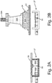
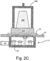
- FIGS. 2A-2C are schematic views of valve system 37 and mounting plate 34 connected to ducting 54, valves 56, and air flow holes 58, with mold 60 and airfoil 38 secured onto the automated air flow pressure tap system 10 of FIG. 1 .
- FIG. 2A shows valve system 37 without mounting plate 34 or airfoil 38.
- FIG. 2B shows valve system 37 and mounting plate 34 with airfoil vane 38A
- FIG. 2C shows valve system 37 and mounting plate 34 with airfoil blade 38B.
- valve system 37 is proximate rotatable plate 12.
- Valve system 37 includes ducting 54, valves 56, and airflow holes 58.
- Valve system 37 receives airflow from airflow system 30, and directs airflow through airfoil 38 as determined by opening and closing of valves 56 in alignment with airflow holes 58.
- airfoil vane 38A is secured in system 10 above valve system 37 on rotating plate 12 by mounting plate 34, clamp 39A, and molds 60A.
- Mounting plate 34 as described with reference to FIG.1 , is secured on rotatable plate 12.
- Mounting plate 34 allows for anchoring of airfoil 38A with repeatable alignment for pressure tapping.
- Ducting 54 in valve system 37 connects airflow system 30 to mounting plate 34 when system 10 is in operation and pressure tapping is occurring.
- Clamp 39A holds airfoil 38A in place on mounting plate 34 while pressure tapping is occurring.
- Molds 60A provide a specific shape and attachment mechanism for airfoil 38 that allows for testing of the specific pattern of holes on airfoil 38.
- valves 56 open and close holes 58.
- different valves 56 will be opened or closed, sealing off some holes 58 for pressure tapping.
- airfoil blade 38B is secured in system 10 above valve system 37 on rotating plate 12 by mounting plate 34, clamp 39B, and mold 60B.
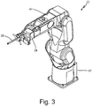
- FIG. 3 is a perspective view of robotic arm 22 used in the automated air flow pressure tap system of FIG. 1 .
- Robotic arm 22 includes base 42 and translatable portion 44.
- Vision system 24 and pressure tapper 26 are mounted on translatable portion 44 of robotic arm 22.
- vision system 24 detects a pattern of holes on airfoil 38, and located a specific hole for pressure tapping.
- Translatable portion 44 of robotic arm 22 moves appropriately to align pressure tapper 26 with the specific hole.
- Pressure tapper 26 sends air to airflow system 30 to record pressure in that specific hole.
- Airflow system 30 takes the pressure reading.
- FIGS. 4A-4B are perspective views of pressure tapper 26 for automated air flow pressure tap system 10 of FIG. 1 in varying embodiments.
- FIG. 4A shows pressure tapper 26A in a configuration that is 90 degrees relative to robotic arm 22.
- FIG. 4B shows pressure tapper 26B in a configuration that is straight relative to robotic arm 22.
- Each configuration of pressure tapper 26 allows for robotic arm 22 to reach and pressure tap holes in an airfoil that are in varying locations or positions.
- System 10 works by combining vision system 24 with robotic arm controlled pressure tapping.
- a human operator loads a mold for a specific airfoil 38 onto mounting plate 34 on first side 18 of rotatable plate 12.
- the operator secures airfoil 38 onto the mold.
- the operator confirms alignment of the mold and airfoil 38. Once alignment is confirmed, the operator rotates first side 18 from operator station 14 to robotic station 16.
- vision system 24 detects the pattern of holes on airfoil 38. In communication with HMI 28, vision system 24 determines which specific hole will be inspected. Robotic arm 22, directed by HMI 28, aligns pressure tapper 26 with the specific hole being inspected. Based on the specific hole being tested, valves 56 open or close to allow air to enter the specified cavity on airfoil 38 and then pressure tapper 26 transfers pressure exiting through the specified hole being tested.. Airflow system 30 provides filtered air to mounting plate 34. Pressure tapper 26 transfers pressure to airflow system 30 through the specific hole being tested.
- rotatable plate 12 can be rotated so that first position 18 is again the operator station 14. There, the human operator can disengage airfoil 38 from the mold, and remove the mold from mounting plate 34. The process can then be repeated with another airfoil, either the same type or different, depending on which mold is attached to mounting plate 34.
- the operations at operator station 14 and robotic station 16 can be performed simultaneously.
- a human operator can be loading an airfoil, checking airfoil alignment, or unloading an airfoil while robotic arm 22 is working to pressure tap an airfoil.
- system 10 allows for minimization of injury to operators that are trying to align pressure tappers in awkward positioning.
- system 10 allows for repeatable pressure tapping of airfoils.
- Programmed robotic arms allow for consistent alignment of pressure tappers with holes in airfoils. Because the alignment is done by detecting an overall pattern of holes on an airfoil with a vision system, system 10 can account for airfoil variations such as casting, grind class, or hole drill true positions.
Landscapes
- Engineering & Computer Science (AREA)
- Mechanical Engineering (AREA)
- Physics & Mathematics (AREA)
- General Physics & Mathematics (AREA)
- Robotics (AREA)
- General Engineering & Computer Science (AREA)
- Human Computer Interaction (AREA)
- Manufacturing & Machinery (AREA)
- Automation & Control Theory (AREA)
- Testing Of Devices, Machine Parts, Or Other Structures Thereof (AREA)
Claims (15)
- Luftstromdruckabgriffssystem (10), umfassend:eine drehbare Platte (12), die eine erste Seite (18) und eine zweite Seite (20) aufweist, wobei jede von der ersten Seite (18) und der zweiten Seite (20) eine Montageplatte (34) umfasst, die konfiguriert ist, um ein aerodynamisches Profil (38) zum Druckabgreifen zu verankern, wobei die Montageplatten (34) jeweils konfiguriert sind, um eine Form (60) zum Befestigen des aerodynamischen Profils (38) aufzunehmen;eine Roboterstation (16), umfassend:
einen Roboterarm (22), der konfiguriert ist, um eine Luftstromprüfung des aerodynamischen Profils (38) vorzunehmen, wobei der Roboterarm (22) Folgendes umfasst:einen Basisabschnitt (42), der den Roboterarm (22) an der Roboterstation (16) verankert; undeinen überführbaren Abschnitt (44), der sich von dem Basisabschnitt (42) erstreckt und bezogen auf diesen beweglich ist;ein Bildverarbeitungssystem (24), das an dem überführbaren Abschnitt (44) des Roboterarms (22) montiert ist, wobei das Bildverarbeitungssystem (24) konfiguriert ist, um ein Lochmuster in dem aerodynamischen Profil (38) zu erfassen; undeine Druckabgriffseinrichtung (26), die an dem überführbaren Abschnitt (44) des Roboterarms (22) montiert und konfiguriert ist, um einzelne Löcher in dem Lochmuster des aerodynamischen Profils (38) zu testen;eine Bedienerstation (14), auf die ein menschlicher Bediener zugreifen kann, wobei die drehbare Platte (12) befestigt ist, sodass durch eine Drehung der drehbaren Platte (12) die Montageplatten (34) zwischen der Roboterstation (16) und der Bedienerstation (14) gedreht werden;ein Ventilsystem (37), das sich nahe der drehbaren Platte (12) befindet, wobei das Ventilsystem (37) konfiguriert ist, um einen Luftstrom der drehbaren Platte (12) bereitzustellen;ein Luftstromsystem (30), das konfiguriert ist, um einen Luftstrom an dem Ventilsystem (37) bereitzustellen; undeine Steuerung (28) in Kommunikation mit der Bedienerstation (14), der Roboterstation (16), den Montageplatten (34), dem Luftstromsystem (30) und dem Ventilsystem (37), wobei die Steuerung (28) konfiguriert ist, um das Bildverarbeitungssystem (24) auf Grundlage des Lochmusters, den Roboterarm (22) und die Druckabgriffseinrichtung (26) zu steuern, wobei die Steuerung (28) zu Folgendem konfiguriert ist:Erfassen des Lochmusters mit dem Bildverarbeitungssystem (24);Lokalisieren eines ersten Loches in dem erfassten Lochmuster, das geprüft werden muss, auf Grundlage eines vorgeladenen Programms, das dem bestimmten aerodynamischen Profil (38) zugeordnet ist;Bewegen der Druckabgriffseinrichtung (26) zu dem ersten Loch mit dem Roboterarm (22); undErfassen eines Luftstroms und Drucks in dem ersten Loch mit der Druckabgriffseinrichtung (26). - System (10) nach Anspruch 1, ferner umfassend ein elektrisches System (32) in Kommunikation mit der Roboterstation (16) und der Bedienungsstation (14), wobei das elektrische System (32) Folgendes umfasst:ein Hochspannungsgehäuse (50);eine Hauptsteuerkonsole (48), die elektrisch mit dem Hochspannungsgehäuse (50) verbunden ist; undeine oder mehrere Wechselstromeinheiten (52), wobei das elektrische System (32) konfiguriert ist, um an der Roboterstation (16) und der Bedienungsstation (14) elektrischen Strom bereitzustellen und das System (10) gegebenenfalls ferner ein Remote-Eingabe-/Ausgabegehäuse in Kommunikation mit dem elektrischen System (32) und der Roboterstation (16) umfasst.
- System (10) nach Anspruch 1 oder 2, wobei das Ventilsystem (37) eine Vielzahl von Zuführlöchern (58) umfasst.
- System (10) nach Anspruch 3, wobei das Ventilsystem (37) eine Vielzahl von Ventilen (56) umfasst, die konfiguriert sind, um einen Luftstrom durch das aerodynamische Profil (38) zu leiten, und wobei jedes der Vielzahl von Ventilen (56) mit einem der Vielzahl von Zuführlöchern (58) ausgerichtet ist.
- System (10) nach Anspruch 3 oder 4, wobei das Ventilsystem (37) derart konfiguriert ist, dass während eines Betriebs des Luftstromdruckabgriffssystems (10) ein einziges Zuführloch (58) offen ist.
- System (10) nach einem der vorangehenden Ansprüche, wobei das Luftstromsystem (30) eine Vielzahl von Sensoren umfasst, die aus der Gruppe bestehend aus Drucksensoren, Temperatursensoren, Düsen und Strömungssensoren ausgewählt sind.
- System (10) nach einem der vorangehenden Ansprüche, wobei das Luftstromsystem (30) einen oder mehrere Luftfilter umfasst.
- System (10) nach einem der vorangehenden Ansprüche, wobei das Bildverarbeitungssystem (24) eine Kamera umfasst.
- System (10) nach einem der vorangehenden Ansprüche, wobei die Druckabgriffseinrichtung (26) bezogen auf den Roboterarm (22) in 90 Grad montiert ist.
- System (10) nach einem der vorangehenden Ansprüche, wobei die Druckabgriffseinrichtung (26) bezogen auf den Roboterarm (22) gerade montiert ist.
- Verfahren zum Luftstromdruckabgreifen, umfassend:Auswählen einer Form (60), die spezifisch für ein aerodynamisches Profil (38) ist;Laden des aerodynamischen Profils (38) und der Form (60) auf eine Montageplatte (34);Bestätigen der Lage des aerodynamischen Profils (38) und der Form (60);Drehen der Montageplatte (34), um das aerodynamische Profil (38) und die Form (60) in die Nähe eines Roboterarms (22) zu bewegen;Finden eines Lochmusters in dem aerodynamischen Profil (38) mit einem Bildverarbeitungssystem (24), das an dem Roboterarm (22) montiert ist;Finden eines ersten Loches in dem erfassen Lochmuster, um auf Grundlage eines vorgeladenen Programms, das dem bestimmten aerodynamischen Profil (38) zugeordnet ist, einen Druck abzugreifen;Bewegen einer Druckabgriffseinrichtung (26), die an dem Roboterarm (22) montiert ist, zu dem ersten Loch unter Verwendung des Roboterarms (22);Strömenlassen von Luft in das erste Loch; undErfassen eines Luftstroms und Drucks in dem ersten Loch mit der Druckabgriffseinrichtung (26), die an dem Roboterarm (22) montiert ist.
- Verfahren nach Anspruch 11, wobei das Laden des aerodynamischen Profils (38) und der Form (60) in eine erste Position durch einen Bediener durchgeführt wird.
- Verfahren nach Anspruch 11 oder 12, wobei das Drehen des aerodynamischen Profils (38) und der Form (60) mit einer Mensch-Maschine-Schnittstelle (28) durchgeführt wird.
- Verfahren nach Anspruch 11, 12 oder 13, wobei das Druckabgreifen des ersten Loches Strömenlassen von Luft durch die Form (60) und das aerodynamische Profil (38) und Erfassen des Druckes des ersten Loches umfasst.
- Verfahren nach einem der Ansprüche 11 bis 14, ferner umfassend Druckabgreifen einer Vielzahl von Löchern.
Applications Claiming Priority (1)
| Application Number | Priority Date | Filing Date | Title |
|---|---|---|---|
| US15/886,259 US10688663B2 (en) | 2018-02-01 | 2018-02-01 | Automation of airfoil pressure taps for testing holes of an airfoil |
Publications (3)
| Publication Number | Publication Date |
|---|---|
| EP3521790A1 EP3521790A1 (de) | 2019-08-07 |
| EP3521790B1 true EP3521790B1 (de) | 2021-01-06 |
| EP3521790B8 EP3521790B8 (de) | 2021-04-07 |
Family
ID=65278272
Family Applications (1)
| Application Number | Title | Priority Date | Filing Date |
|---|---|---|---|
| EP19155137.3A Active EP3521790B8 (de) | 2018-02-01 | 2019-02-01 | Automatisierung des test von kühlöffnungen eines aerodynamischen profils |
Country Status (2)
| Country | Link |
|---|---|
| US (1) | US10688663B2 (de) |
| EP (1) | EP3521790B8 (de) |
Families Citing this family (8)
| Publication number | Priority date | Publication date | Assignee | Title |
|---|---|---|---|---|
| US10710272B2 (en) * | 2017-12-14 | 2020-07-14 | United Technologies Corporation | Hybrid material airflow impression molds |
| US11274599B2 (en) | 2019-03-27 | 2022-03-15 | Pratt & Whitney Canada Corp. | Air system switching system to allow aero-engines to operate in standby mode |
| US11391219B2 (en) | 2019-04-18 | 2022-07-19 | Pratt & Whitney Canada Corp. | Health monitor for air switching system |
| US11274611B2 (en) | 2019-05-31 | 2022-03-15 | Pratt & Whitney Canada Corp. | Control logic for gas turbine engine fuel economy |
| US11859563B2 (en) | 2019-05-31 | 2024-01-02 | Pratt & Whitney Canada Corp. | Air system of multi-engine aircraft |
| US11326525B2 (en) | 2019-10-11 | 2022-05-10 | Pratt & Whitney Canada Corp. | Aircraft bleed air systems and methods |
| CN111319789B (zh) * | 2020-04-09 | 2021-08-06 | 中国空气动力研究与发展中心低速空气动力研究所 | 一种全尺寸螺旋桨桨叶结冰风洞试验方法 |
| CN113955146B (zh) * | 2021-10-12 | 2023-03-31 | 南京航空航天大学 | 一种防冰冷负荷分布试验的模拟装置 |
Family Cites Families (9)
| Publication number | Priority date | Publication date | Assignee | Title |
|---|---|---|---|---|
| US7679746B1 (en) | 2009-01-25 | 2010-03-16 | The Boeing Company | System and method for measurement of pressure drop through perforated panels |
| GB0914904D0 (en) | 2009-08-27 | 2009-09-30 | Rolls Royce Plc | Inspection of holes |
| US8244488B2 (en) | 2009-11-25 | 2012-08-14 | General Electric Company | Thermal inspection systems |
| US8530787B2 (en) | 2009-12-16 | 2013-09-10 | Flow Systems, Inc. | Flow tester for laser drilled holes |
| WO2011131263A1 (de) | 2010-04-23 | 2011-10-27 | Siemens Aktiengesellschaft | Prüfsystem zur überprüfung von turbinenschaufeln |
| US9476842B2 (en) | 2010-05-03 | 2016-10-25 | United Technologies Corporation | On-the-fly dimensional imaging inspection |
| US9188504B2 (en) | 2012-10-31 | 2015-11-17 | General Electric Company | Methods for testing turbine blades |
| US9683460B2 (en) | 2014-07-11 | 2017-06-20 | General Electric Company | System and method for inspecting turbomachines |
| EP3034994B1 (de) | 2014-12-19 | 2017-08-23 | Rolls-Royce plc | System und verfahren zur spitzenleckmessung |
-
2018
- 2018-02-01 US US15/886,259 patent/US10688663B2/en active Active
-
2019
- 2019-02-01 EP EP19155137.3A patent/EP3521790B8/de active Active
Non-Patent Citations (1)
| Title |
|---|
| None * |
Also Published As
| Publication number | Publication date |
|---|---|
| EP3521790A1 (de) | 2019-08-07 |
| EP3521790B8 (de) | 2021-04-07 |
| US20190232497A1 (en) | 2019-08-01 |
| US10688663B2 (en) | 2020-06-23 |
Similar Documents
| Publication | Publication Date | Title |
|---|---|---|
| EP3521790B1 (de) | Automatisierung des test von kühlöffnungen eines aerodynamischen profils | |
| JP5898942B2 (ja) | 熱検査・機械加工システムおよび使用方法 | |
| EP3492214B1 (de) | Verfahren zu automatischen fahrzeugkarosserieschweisspunktinspektion und -steuerung | |
| EP2881731B1 (de) | Thermografische Prüftechniken | |
| US6907358B2 (en) | Eddy current inspection method | |
| EP3130971A1 (de) | Maschinenwerkzeugbahnkompensierung mit vibrationserfassung | |
| US4802195A (en) | Device for method for manipulating a part | |
| US20130269426A1 (en) | Turbine inspection system and related method of operation | |
| CN1602236A (zh) | 一种从燃气涡轮发动机构件的冷却孔中除去涂层材料的方法 | |
| JPS621241A (ja) | 半導体ウエハをテストする装置及び方法 | |
| WO2015167782A1 (en) | Arrangement for laser processing of turbine component with a fixture and plate(s) having/forming an opening | |
| BR112013027248B1 (pt) | método para o teste funcional de turbomáquinas e dispositivo de teste para as mesmas | |
| EP2610438B1 (de) | Luftstromprüfverfahren und System für Schaufeln mit mehreren Hohlräumen | |
| CN203190943U (zh) | 气门液压挺杆自动检测装置 | |
| CN109297407A (zh) | 一种精密电子部件任意斜孔位置度及孔径螺牙检测装置 | |
| CN104370075B (zh) | 一种用于转盘的定位装置、转盘机构及刻蚀设备 | |
| JPH06349909A (ja) | プローブ検査装置 | |
| US9205507B2 (en) | Nuclear power plant construction preparation unit, nuclear power plant construction system, and nuclear power plant construction method | |
| JPH08166325A (ja) | 空気圧アクチュエータを用いた複数のバルブの異常監視方法 | |
| CN109297408A (zh) | 高速自动化检测精密器件任意孔向孔径螺牙及位置度的专用装置 | |
| JP2009139287A (ja) | 部品検査装置 | |
| KR102101791B1 (ko) | 유체 제어밸브의 온도센서 검사 시스템 | |
| CN119738763B (zh) | 一种指针万用表智能化自动检定系统 | |
| CN209147924U (zh) | 高速自动检测精密器件任意孔向孔径螺牙及位置度装置 | |
| CN107843645A (zh) | 用于车身焊接的涡流检测装置 |
Legal Events
| Date | Code | Title | Description |
|---|---|---|---|
| PUAI | Public reference made under article 153(3) epc to a published international application that has entered the european phase |
Free format text: ORIGINAL CODE: 0009012 |
|
| STAA | Information on the status of an ep patent application or granted ep patent |
Free format text: STATUS: THE APPLICATION HAS BEEN PUBLISHED |
|
| AK | Designated contracting states |
Kind code of ref document: A1 Designated state(s): AL AT BE BG CH CY CZ DE DK EE ES FI FR GB GR HR HU IE IS IT LI LT LU LV MC MK MT NL NO PL PT RO RS SE SI SK SM TR |
|
| AX | Request for extension of the european patent |
Extension state: BA ME |
|
| STAA | Information on the status of an ep patent application or granted ep patent |
Free format text: STATUS: REQUEST FOR EXAMINATION WAS MADE |
|
| 17P | Request for examination filed |
Effective date: 20200207 |
|
| RBV | Designated contracting states (corrected) |
Designated state(s): AL AT BE BG CH CY CZ DE DK EE ES FI FR GB GR HR HU IE IS IT LI LT LU LV MC MK MT NL NO PL PT RO RS SE SI SK SM TR |
|
| GRAP | Despatch of communication of intention to grant a patent |
Free format text: ORIGINAL CODE: EPIDOSNIGR1 |
|
| STAA | Information on the status of an ep patent application or granted ep patent |
Free format text: STATUS: GRANT OF PATENT IS INTENDED |
|
| RIC1 | Information provided on ipc code assigned before grant |
Ipc: G05B 19/401 20060101ALI20200629BHEP Ipc: G01M 9/06 20060101AFI20200629BHEP Ipc: G01M 99/00 20110101ALI20200629BHEP Ipc: F01D 21/00 20060101ALI20200629BHEP Ipc: B25J 9/16 20060101ALI20200629BHEP Ipc: F01D 25/28 20060101ALI20200629BHEP |
|
| INTG | Intention to grant announced |
Effective date: 20200729 |
|
| RIN1 | Information on inventor provided before grant (corrected) |
Inventor name: SANSEVERO, PEGGY Inventor name: TALL, MARY LYNN |
|
| GRAS | Grant fee paid |
Free format text: ORIGINAL CODE: EPIDOSNIGR3 |
|
| GRAA | (expected) grant |
Free format text: ORIGINAL CODE: 0009210 |
|
| STAA | Information on the status of an ep patent application or granted ep patent |
Free format text: STATUS: THE PATENT HAS BEEN GRANTED |
|
| AK | Designated contracting states |
Kind code of ref document: B1 Designated state(s): AL AT BE BG CH CY CZ DE DK EE ES FI FR GB GR HR HU IE IS IT LI LT LU LV MC MK MT NL NO PL PT RO RS SE SI SK SM TR |
|
| REG | Reference to a national code |
Ref country code: GB Ref legal event code: FG4D |
|
| REG | Reference to a national code |
Ref country code: AT Ref legal event code: REF Ref document number: 1352887 Country of ref document: AT Kind code of ref document: T Effective date: 20210115 Ref country code: CH Ref legal event code: EP |
|
| REG | Reference to a national code |
Ref country code: DE Ref legal event code: R096 Ref document number: 602019002010 Country of ref document: DE |
|
| REG | Reference to a national code |
Ref country code: IE Ref legal event code: FG4D |
|
| REG | Reference to a national code |
Ref country code: DE Ref legal event code: R081 Ref document number: 602019002010 Country of ref document: DE Owner name: RAYTHEON TECHNOLOGIES CORPORATION, FARMINGTON, US Free format text: FORMER OWNER: UNITED TECHNOLOGIES CORPORATION, FARMINGTON, CONN., US Ref country code: DE Ref legal event code: R081 Ref document number: 602019002010 Country of ref document: DE Owner name: RTX CORPORATION (N.D.GES.D. STAATES DELAWARE),, US Free format text: FORMER OWNER: UNITED TECHNOLOGIES CORPORATION, FARMINGTON, CONN., US |
|
| REG | Reference to a national code |
Ref country code: CH Ref legal event code: PK Free format text: BERICHTIGUNG B8 |
|
| RAP2 | Party data changed (patent owner data changed or rights of a patent transferred) |
Owner name: RAYTHEON TECHNOLOGIES CORPORATION |
|
| REG | Reference to a national code |
Ref country code: NL Ref legal event code: MP Effective date: 20210106 |
|
| REG | Reference to a national code |
Ref country code: AT Ref legal event code: MK05 Ref document number: 1352887 Country of ref document: AT Kind code of ref document: T Effective date: 20210106 |
|
| REG | Reference to a national code |
Ref country code: LT Ref legal event code: MG9D |
|
| PG25 | Lapsed in a contracting state [announced via postgrant information from national office to epo] |
Ref country code: LT Free format text: LAPSE BECAUSE OF FAILURE TO SUBMIT A TRANSLATION OF THE DESCRIPTION OR TO PAY THE FEE WITHIN THE PRESCRIBED TIME-LIMIT Effective date: 20210106 Ref country code: NO Free format text: LAPSE BECAUSE OF FAILURE TO SUBMIT A TRANSLATION OF THE DESCRIPTION OR TO PAY THE FEE WITHIN THE PRESCRIBED TIME-LIMIT Effective date: 20210406 Ref country code: PT Free format text: LAPSE BECAUSE OF FAILURE TO SUBMIT A TRANSLATION OF THE DESCRIPTION OR TO PAY THE FEE WITHIN THE PRESCRIBED TIME-LIMIT Effective date: 20210506 Ref country code: BG Free format text: LAPSE BECAUSE OF FAILURE TO SUBMIT A TRANSLATION OF THE DESCRIPTION OR TO PAY THE FEE WITHIN THE PRESCRIBED TIME-LIMIT Effective date: 20210406 Ref country code: GR Free format text: LAPSE BECAUSE OF FAILURE TO SUBMIT A TRANSLATION OF THE DESCRIPTION OR TO PAY THE FEE WITHIN THE PRESCRIBED TIME-LIMIT Effective date: 20210407 Ref country code: HR Free format text: LAPSE BECAUSE OF FAILURE TO SUBMIT A TRANSLATION OF THE DESCRIPTION OR TO PAY THE FEE WITHIN THE PRESCRIBED TIME-LIMIT Effective date: 20210106 Ref country code: FI Free format text: LAPSE BECAUSE OF FAILURE TO SUBMIT A TRANSLATION OF THE DESCRIPTION OR TO PAY THE FEE WITHIN THE PRESCRIBED TIME-LIMIT Effective date: 20210106 |
|
| PG25 | Lapsed in a contracting state [announced via postgrant information from national office to epo] |
Ref country code: AT Free format text: LAPSE BECAUSE OF FAILURE TO SUBMIT A TRANSLATION OF THE DESCRIPTION OR TO PAY THE FEE WITHIN THE PRESCRIBED TIME-LIMIT Effective date: 20210106 Ref country code: LV Free format text: LAPSE BECAUSE OF FAILURE TO SUBMIT A TRANSLATION OF THE DESCRIPTION OR TO PAY THE FEE WITHIN THE PRESCRIBED TIME-LIMIT Effective date: 20210106 Ref country code: RS Free format text: LAPSE BECAUSE OF FAILURE TO SUBMIT A TRANSLATION OF THE DESCRIPTION OR TO PAY THE FEE WITHIN THE PRESCRIBED TIME-LIMIT Effective date: 20210106 Ref country code: PL Free format text: LAPSE BECAUSE OF FAILURE TO SUBMIT A TRANSLATION OF THE DESCRIPTION OR TO PAY THE FEE WITHIN THE PRESCRIBED TIME-LIMIT Effective date: 20210106 Ref country code: SE Free format text: LAPSE BECAUSE OF FAILURE TO SUBMIT A TRANSLATION OF THE DESCRIPTION OR TO PAY THE FEE WITHIN THE PRESCRIBED TIME-LIMIT Effective date: 20210106 |
|
| PG25 | Lapsed in a contracting state [announced via postgrant information from national office to epo] |
Ref country code: IS Free format text: LAPSE BECAUSE OF FAILURE TO SUBMIT A TRANSLATION OF THE DESCRIPTION OR TO PAY THE FEE WITHIN THE PRESCRIBED TIME-LIMIT Effective date: 20210506 |
|
| REG | Reference to a national code |
Ref country code: DE Ref legal event code: R097 Ref document number: 602019002010 Country of ref document: DE |
|
| REG | Reference to a national code |
Ref country code: BE Ref legal event code: MM Effective date: 20210228 |
|
| PG25 | Lapsed in a contracting state [announced via postgrant information from national office to epo] |
Ref country code: SM Free format text: LAPSE BECAUSE OF FAILURE TO SUBMIT A TRANSLATION OF THE DESCRIPTION OR TO PAY THE FEE WITHIN THE PRESCRIBED TIME-LIMIT Effective date: 20210106 Ref country code: CZ Free format text: LAPSE BECAUSE OF FAILURE TO SUBMIT A TRANSLATION OF THE DESCRIPTION OR TO PAY THE FEE WITHIN THE PRESCRIBED TIME-LIMIT Effective date: 20210106 Ref country code: EE Free format text: LAPSE BECAUSE OF FAILURE TO SUBMIT A TRANSLATION OF THE DESCRIPTION OR TO PAY THE FEE WITHIN THE PRESCRIBED TIME-LIMIT Effective date: 20210106 Ref country code: LU Free format text: LAPSE BECAUSE OF NON-PAYMENT OF DUE FEES Effective date: 20210201 Ref country code: MC Free format text: LAPSE BECAUSE OF FAILURE TO SUBMIT A TRANSLATION OF THE DESCRIPTION OR TO PAY THE FEE WITHIN THE PRESCRIBED TIME-LIMIT Effective date: 20210106 |
|
| PLBE | No opposition filed within time limit |
Free format text: ORIGINAL CODE: 0009261 |
|
| STAA | Information on the status of an ep patent application or granted ep patent |
Free format text: STATUS: NO OPPOSITION FILED WITHIN TIME LIMIT |
|
| PG25 | Lapsed in a contracting state [announced via postgrant information from national office to epo] |
Ref country code: SK Free format text: LAPSE BECAUSE OF FAILURE TO SUBMIT A TRANSLATION OF THE DESCRIPTION OR TO PAY THE FEE WITHIN THE PRESCRIBED TIME-LIMIT Effective date: 20210106 Ref country code: RO Free format text: LAPSE BECAUSE OF FAILURE TO SUBMIT A TRANSLATION OF THE DESCRIPTION OR TO PAY THE FEE WITHIN THE PRESCRIBED TIME-LIMIT Effective date: 20210106 Ref country code: DK Free format text: LAPSE BECAUSE OF FAILURE TO SUBMIT A TRANSLATION OF THE DESCRIPTION OR TO PAY THE FEE WITHIN THE PRESCRIBED TIME-LIMIT Effective date: 20210106 |
|
| 26N | No opposition filed |
Effective date: 20211007 |
|
| PG25 | Lapsed in a contracting state [announced via postgrant information from national office to epo] |
Ref country code: ES Free format text: LAPSE BECAUSE OF FAILURE TO SUBMIT A TRANSLATION OF THE DESCRIPTION OR TO PAY THE FEE WITHIN THE PRESCRIBED TIME-LIMIT Effective date: 20210106 Ref country code: AL Free format text: LAPSE BECAUSE OF FAILURE TO SUBMIT A TRANSLATION OF THE DESCRIPTION OR TO PAY THE FEE WITHIN THE PRESCRIBED TIME-LIMIT Effective date: 20210106 Ref country code: IE Free format text: LAPSE BECAUSE OF NON-PAYMENT OF DUE FEES Effective date: 20210201 |
|
| PG25 | Lapsed in a contracting state [announced via postgrant information from national office to epo] |
Ref country code: SI Free format text: LAPSE BECAUSE OF FAILURE TO SUBMIT A TRANSLATION OF THE DESCRIPTION OR TO PAY THE FEE WITHIN THE PRESCRIBED TIME-LIMIT Effective date: 20210106 |
|
| PG25 | Lapsed in a contracting state [announced via postgrant information from national office to epo] |
Ref country code: IT Free format text: LAPSE BECAUSE OF FAILURE TO SUBMIT A TRANSLATION OF THE DESCRIPTION OR TO PAY THE FEE WITHIN THE PRESCRIBED TIME-LIMIT Effective date: 20210106 |
|
| PG25 | Lapsed in a contracting state [announced via postgrant information from national office to epo] |
Ref country code: IS Free format text: LAPSE BECAUSE OF FAILURE TO SUBMIT A TRANSLATION OF THE DESCRIPTION OR TO PAY THE FEE WITHIN THE PRESCRIBED TIME-LIMIT Effective date: 20210506 |
|
| PG25 | Lapsed in a contracting state [announced via postgrant information from national office to epo] |
Ref country code: BE Free format text: LAPSE BECAUSE OF NON-PAYMENT OF DUE FEES Effective date: 20210228 |
|
| REG | Reference to a national code |
Ref country code: CH Ref legal event code: PL |
|
| PG25 | Lapsed in a contracting state [announced via postgrant information from national office to epo] |
Ref country code: LI Free format text: LAPSE BECAUSE OF NON-PAYMENT OF DUE FEES Effective date: 20220228 Ref country code: CH Free format text: LAPSE BECAUSE OF NON-PAYMENT OF DUE FEES Effective date: 20220228 |
|
| P01 | Opt-out of the competence of the unified patent court (upc) registered |
Effective date: 20230521 |
|
| PG25 | Lapsed in a contracting state [announced via postgrant information from national office to epo] |
Ref country code: NL Free format text: LAPSE BECAUSE OF NON-PAYMENT OF DUE FEES Effective date: 20210206 Ref country code: CY Free format text: LAPSE BECAUSE OF FAILURE TO SUBMIT A TRANSLATION OF THE DESCRIPTION OR TO PAY THE FEE WITHIN THE PRESCRIBED TIME-LIMIT Effective date: 20210106 |
|
| PG25 | Lapsed in a contracting state [announced via postgrant information from national office to epo] |
Ref country code: HU Free format text: LAPSE BECAUSE OF FAILURE TO SUBMIT A TRANSLATION OF THE DESCRIPTION OR TO PAY THE FEE WITHIN THE PRESCRIBED TIME-LIMIT; INVALID AB INITIO Effective date: 20190201 |
|
| PG25 | Lapsed in a contracting state [announced via postgrant information from national office to epo] |
Ref country code: MK Free format text: LAPSE BECAUSE OF FAILURE TO SUBMIT A TRANSLATION OF THE DESCRIPTION OR TO PAY THE FEE WITHIN THE PRESCRIBED TIME-LIMIT Effective date: 20210106 |
|
| PG25 | Lapsed in a contracting state [announced via postgrant information from national office to epo] |
Ref country code: MT Free format text: LAPSE BECAUSE OF FAILURE TO SUBMIT A TRANSLATION OF THE DESCRIPTION OR TO PAY THE FEE WITHIN THE PRESCRIBED TIME-LIMIT Effective date: 20210106 |
|
| PGFP | Annual fee paid to national office [announced via postgrant information from national office to epo] |
Ref country code: DE Payment date: 20250122 Year of fee payment: 7 |
|
| PGFP | Annual fee paid to national office [announced via postgrant information from national office to epo] |
Ref country code: FR Payment date: 20250121 Year of fee payment: 7 |
|
| PGFP | Annual fee paid to national office [announced via postgrant information from national office to epo] |
Ref country code: GB Payment date: 20250123 Year of fee payment: 7 |
|
| REG | Reference to a national code |
Ref country code: DE Ref legal event code: R081 Ref document number: 602019002010 Country of ref document: DE Owner name: RTX CORPORATION (N.D.GES.D. STAATES DELAWARE),, US Free format text: FORMER OWNER: RAYTHEON TECHNOLOGIES CORPORATION, FARMINGTON, CT, US |
|
| PG25 | Lapsed in a contracting state [announced via postgrant information from national office to epo] |
Ref country code: TR Free format text: LAPSE BECAUSE OF FAILURE TO SUBMIT A TRANSLATION OF THE DESCRIPTION OR TO PAY THE FEE WITHIN THE PRESCRIBED TIME-LIMIT Effective date: 20210106 |