EP3521745B1 - Ensemble ailette et tube plat d'un échangeur de chaleur - Google Patents
Ensemble ailette et tube plat d'un échangeur de chaleur Download PDFInfo
- Publication number
- EP3521745B1 EP3521745B1 EP18461515.1A EP18461515A EP3521745B1 EP 3521745 B1 EP3521745 B1 EP 3521745B1 EP 18461515 A EP18461515 A EP 18461515A EP 3521745 B1 EP3521745 B1 EP 3521745B1
- Authority
- EP
- European Patent Office
- Prior art keywords
- wall
- distance
- flat tube
- adjacent
- bent portion
- Prior art date
- Legal status (The legal status is an assumption and is not a legal conclusion. Google has not performed a legal analysis and makes no representation as to the accuracy of the status listed.)
- Active
Links
- 239000000463 material Substances 0.000 claims description 10
- 239000012530 fluid Substances 0.000 description 7
- 238000000034 method Methods 0.000 description 3
- 238000009827 uniform distribution Methods 0.000 description 2
- 230000006978 adaptation Effects 0.000 description 1
- 230000001419 dependent effect Effects 0.000 description 1
- 238000009826 distribution Methods 0.000 description 1
- 230000000694 effects Effects 0.000 description 1
- XLYOFNOQVPJJNP-UHFFFAOYSA-N water Substances O XLYOFNOQVPJJNP-UHFFFAOYSA-N 0.000 description 1
Images
Classifications
-
- F—MECHANICAL ENGINEERING; LIGHTING; HEATING; WEAPONS; BLASTING
- F28—HEAT EXCHANGE IN GENERAL
- F28F—DETAILS OF HEAT-EXCHANGE AND HEAT-TRANSFER APPARATUS, OF GENERAL APPLICATION
- F28F1/00—Tubular elements; Assemblies of tubular elements
- F28F1/02—Tubular elements of cross-section which is non-circular
-
- F—MECHANICAL ENGINEERING; LIGHTING; HEATING; WEAPONS; BLASTING
- F28—HEAT EXCHANGE IN GENERAL
- F28D—HEAT-EXCHANGE APPARATUS, NOT PROVIDED FOR IN ANOTHER SUBCLASS, IN WHICH THE HEAT-EXCHANGE MEDIA DO NOT COME INTO DIRECT CONTACT
- F28D1/00—Heat-exchange apparatus having stationary conduit assemblies for one heat-exchange medium only, the media being in contact with different sides of the conduit wall, in which the other heat-exchange medium is a large body of fluid, e.g. domestic or motor car radiators
- F28D1/02—Heat-exchange apparatus having stationary conduit assemblies for one heat-exchange medium only, the media being in contact with different sides of the conduit wall, in which the other heat-exchange medium is a large body of fluid, e.g. domestic or motor car radiators with heat-exchange conduits immersed in the body of fluid
- F28D1/03—Heat-exchange apparatus having stationary conduit assemblies for one heat-exchange medium only, the media being in contact with different sides of the conduit wall, in which the other heat-exchange medium is a large body of fluid, e.g. domestic or motor car radiators with heat-exchange conduits immersed in the body of fluid with plate-like or laminated conduits
- F28D1/0391—Heat-exchange apparatus having stationary conduit assemblies for one heat-exchange medium only, the media being in contact with different sides of the conduit wall, in which the other heat-exchange medium is a large body of fluid, e.g. domestic or motor car radiators with heat-exchange conduits immersed in the body of fluid with plate-like or laminated conduits a single plate being bent to form one or more conduits
-
- F—MECHANICAL ENGINEERING; LIGHTING; HEATING; WEAPONS; BLASTING
- F28—HEAT EXCHANGE IN GENERAL
- F28D—HEAT-EXCHANGE APPARATUS, NOT PROVIDED FOR IN ANOTHER SUBCLASS, IN WHICH THE HEAT-EXCHANGE MEDIA DO NOT COME INTO DIRECT CONTACT
- F28D1/00—Heat-exchange apparatus having stationary conduit assemblies for one heat-exchange medium only, the media being in contact with different sides of the conduit wall, in which the other heat-exchange medium is a large body of fluid, e.g. domestic or motor car radiators
- F28D1/02—Heat-exchange apparatus having stationary conduit assemblies for one heat-exchange medium only, the media being in contact with different sides of the conduit wall, in which the other heat-exchange medium is a large body of fluid, e.g. domestic or motor car radiators with heat-exchange conduits immersed in the body of fluid
- F28D1/04—Heat-exchange apparatus having stationary conduit assemblies for one heat-exchange medium only, the media being in contact with different sides of the conduit wall, in which the other heat-exchange medium is a large body of fluid, e.g. domestic or motor car radiators with heat-exchange conduits immersed in the body of fluid with tubular conduits
- F28D1/053—Heat-exchange apparatus having stationary conduit assemblies for one heat-exchange medium only, the media being in contact with different sides of the conduit wall, in which the other heat-exchange medium is a large body of fluid, e.g. domestic or motor car radiators with heat-exchange conduits immersed in the body of fluid with tubular conduits the conduits being straight
- F28D1/0535—Heat-exchange apparatus having stationary conduit assemblies for one heat-exchange medium only, the media being in contact with different sides of the conduit wall, in which the other heat-exchange medium is a large body of fluid, e.g. domestic or motor car radiators with heat-exchange conduits immersed in the body of fluid with tubular conduits the conduits being straight the conduits having a non-circular cross-section
- F28D1/05366—Assemblies of conduits connected to common headers, e.g. core type radiators
-
- F—MECHANICAL ENGINEERING; LIGHTING; HEATING; WEAPONS; BLASTING
- F28—HEAT EXCHANGE IN GENERAL
- F28F—DETAILS OF HEAT-EXCHANGE AND HEAT-TRANSFER APPARATUS, OF GENERAL APPLICATION
- F28F1/00—Tubular elements; Assemblies of tubular elements
- F28F1/10—Tubular elements and assemblies thereof with means for increasing heat-transfer area, e.g. with fins, with projections, with recesses
- F28F1/40—Tubular elements and assemblies thereof with means for increasing heat-transfer area, e.g. with fins, with projections, with recesses the means being only inside the tubular element
-
- F—MECHANICAL ENGINEERING; LIGHTING; HEATING; WEAPONS; BLASTING
- F28—HEAT EXCHANGE IN GENERAL
- F28F—DETAILS OF HEAT-EXCHANGE AND HEAT-TRANSFER APPARATUS, OF GENERAL APPLICATION
- F28F3/00—Plate-like or laminated elements; Assemblies of plate-like or laminated elements
- F28F3/02—Elements or assemblies thereof with means for increasing heat-transfer area, e.g. with fins, with recesses, with corrugations
- F28F3/025—Elements or assemblies thereof with means for increasing heat-transfer area, e.g. with fins, with recesses, with corrugations the means being corrugated, plate-like elements
-
- F—MECHANICAL ENGINEERING; LIGHTING; HEATING; WEAPONS; BLASTING
- F28—HEAT EXCHANGE IN GENERAL
- F28D—HEAT-EXCHANGE APPARATUS, NOT PROVIDED FOR IN ANOTHER SUBCLASS, IN WHICH THE HEAT-EXCHANGE MEDIA DO NOT COME INTO DIRECT CONTACT
- F28D21/00—Heat-exchange apparatus not covered by any of the groups F28D1/00 - F28D20/00
- F28D2021/0019—Other heat exchangers for particular applications; Heat exchange systems not otherwise provided for
- F28D2021/008—Other heat exchangers for particular applications; Heat exchange systems not otherwise provided for for vehicles
Definitions
- the invention relates to a tube assembly for a heat exchanger. More particularly, the present invention relates to a tube assembly with a flat tube and a corrugated fin for a heat exchanger used in the automotive industry.
- the heat exchange can take place between two fluids.
- the first fluid can be guided through a conduit formed by elements of the heat exchanger.
- These can be two manifolds connected fluidically by means of tubes.
- One of the fluids travels through these tubes between said manifolds.
- the tubes conduct the heat of the first fluid which is then transferred to the second fluid, or vice versa.
- flat tubes which in cross-section have an elongated shape defined by two parallel walls connected at their side edges by side walls of substantially smaller height. These tubes are generally placed one above the other so that their neighboring flat, parallel walls form channels for the second fluid.
- the tubes can comprise inner fins, for example in form of corrugated sheets, the bent portions of which are in contact with said flat parallel walls of the flat tubes. These fins facilitate the heat exchange.
- the example of such tubes is described in patent applications with publication numbers EP1089047A2 and EP1906127A2 .
- DE 10 2008 013 018 A1 describes a flat tube assembly according to the preamble of claim 1.
- the object of the invention is flat tube assembly for a heat exchanger, as defined by claim 1, comprising a flat tube and a fin placed inside the tube, the flat tube being formed by a sheet material and being defined by a bottom wall, a top wall and two side walls, the distance between the bottom wall and the top wall defining the height direction H with tube height Ht, and the distance between the side walls defining the width direction W, wherein at least one of the side walls and a corner section between the bottom wall and this side wall are formed by layers of the sheet material, and wherein the fin is a corrugated sheet with plurality of adjacent walls joined at top and bottom bent portions which are in contact with the top and bottom walls of the tube respectively, the adjacent bent portions being distanced from each other by substantially constant distance T1, wherein a terminal adjacent wall of the fin has a bottom side edge which is distanced from the adjacent bottom bent portion, along the width direction W, by a distance T2 which is bigger than distance T1, and is distanced from the top wall, along the height direction H, by a distance Hf
- the bottom side edge of the terminal adjacent wall of the fin is in contact with the side wall of the flat tube.
- the terminal adjacent wall has a bent portion so that the terminal adjacent wall runs substantially in parallel to the side wall, in a distanced manner, between said bent portion and the bottom side edge.
- the bent portion is located closer to the last top bent portion than to the bottom side edge.
- the distance Hf between the bottom side edge and the top wall is 6 mm, while the distance Ht between the bottom wall and the top wall is 7 mm.
- the distance T2 between the bottom side edge and the adjacent bottom bent portion is 4,5 mm, while the distance T1 between the adjacent bottom end portions 22 is 2,5 mm.
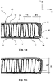
- Figs. 1a and 1b show a tube assembly according to the invention.
- Figs. 1a and 1b show a tube assembly according to the invention. It is to be noted that both these figures present the same tube assembly - the same embodiment is presented twice to provide space for reference signs in a clear manner. The description thus relates to both these figures interchangeably.
- the figures show a flat tube assembly 1 for a heat exchanger.
- the heat exchanger can be a charge air cooler, water charge air cooler, condenser, radiator and the like.
- the flat tube assembly 1 comprises a flat tube 10 and a fin 20 placed inside the tube 10.
- the flat tube 10 is formed by a sheet material and is defined by a bottom wall 11, a top wall 12 and two side walls 13.
- the side walls can be completely arcuate or can comprise a flat middle section.
- the distance between the bottom wall 11 and the top wall 12 defines the height direction H.
- Tube height Ht is measured along this distance.
- tube height Ht is the shortest distance between the flat, parallel walls 11, 12 of the flat tube.
- the distance between the side walls 13 defines the width direction W. This width direction is to be understood to run parallel to the flat, parallel walls 11, 12.
- At least one of the side walls 13 and a corner section 14 between the bottom wall 11 and this side wall 13 are formed by layers of the sheet material.
- the sides of the sheet overlap one onto the other at one of the sides. Consequently, at least one of the side walls have a layered structure.
- at least one of the corner sections at the joint between bottom wall and a side wall will also be layered.
- the fin 20 is a corrugated sheet comprising a plurality of adjacent walls joined at top and bottom bent portions 22 which are in contact with the top and bottom walls 11, 12 of the tube 10 respectively.
- the top and bottom bent portions 22 form ridges of the folds which form corrugations.
- the adjacent bent portions 22 are distanced from each other by substantially constant distance T1, which means that the neighboring bottom bent portions are separated from each other by the distance T1, and the neighboring top bent portions are also separated from each other by the distance T1.
- This bottom side edge 23 is the terminal part of the terminal adjacent wall.
- the bottom side edge 23 is distanced from the adjacent bottom bent portion 22, along the width direction W, by a distance T2 which is bigger than distance T1.
- it is distanced from the top wall 12, along the height direction H, by a distance Hf which is smaller than Ht.
- the bottom side edge 23 of the terminal adjacent wall 21 of the fin 10 may be in contact with the side wall 13 of the flat tube 10, preferably connected permanently to it.
- the terminal adjacent wall 21 can comprise a bent portion 24, as shown in Figs. 1a and 1b .
- This bent portion 24 is located between the last top bent portion 22 and the bottom side edge 23, preferably closer to the former.
- the bent portion 24 is shaped so that the terminal adjacent wall 21 runs substantially in parallel to the side wall 13, in a distanced manner, between said bent portion 24 and the bottom side edge 23.
- the general shape of the side wall 13 is followed in a substantially parallel manner by the general shaper of the terminal adjacent wall 21. This enhances the uniform distribution of the fin within the tube and reduces to a greater extent, and with appropriately chosen distancing - possibly eliminates, the air by-pass.
- the distance Hf between the bottom side edge 23 and the top wall 11 may be 6 mm, while the distance Ht between the bottom wall 11 and the top wall 12 may be 7 mm.
- the distance T2 between the bottom side edge 23 and the adjacent bottom bent portion 22 may be 4,5mm, while the distance T1 between the adjacent bottom end portions 22 may be 2,5 mm.
- both side walls and their respective corner sections can have a layered structure.
- the structure of the end wall of the fin will then apply analogously to both sides, with a logical adaptation of dependencies between elements denoted as 'top' elements and 'bottom' elements.
Landscapes
- Engineering & Computer Science (AREA)
- Physics & Mathematics (AREA)
- Thermal Sciences (AREA)
- Mechanical Engineering (AREA)
- General Engineering & Computer Science (AREA)
- Geometry (AREA)
- Heat-Exchange Devices With Radiators And Conduit Assemblies (AREA)
Claims (5)
- Ensemble ailette et tube plat 1 pour échangeur de chaleur, comprenant un tube plat 10 et une ailette 20 placée à l'intérieur du tube 10, le tube plat 10 étant formé par un matériau en feuille et étant défini par une paroi inférieure 11, une paroi supérieure 12 et deux parois latérales 13, la distance entre la paroi inférieure 11 et la paroi supérieure 12 définissant la direction de la hauteur H avec la hauteur du tube Ht, et la distance entre les parois latérales 13 définissant la direction de la largeur W, au moins l'une des parois latérales 13 et une section de coin 14 entre la paroi inférieure 11 et cette paroi latérale 13 étant formées par des couches du matériau en feuille, et l'ailette 20 étant une feuille ondulée avec une pluralité de parois adjacentes jointes à des parties pliées supérieure et inférieure 22 qui sont en contact avec les parois supérieure et inférieure 11, 12 du tube 10 respectivement, les parties pliées 22 adjacentes étant espacées les unes des autres d'une distance sensiblement constante T1, une paroi adjacente terminale 21 de l'ailette 10 ayant un bord latéral inférieur 23 qui est espacé de la partie pliée inférieure 22 adjacente, dans le sens de la largeur W, d'une distance T2 qui est supérieure à la distance T1, et est espacé de la paroi supérieure 12, dans le sens de la hauteur H, d'une distance Hf qui est inférieure à Ht, caractérisé en ce que la paroi adjacente terminale 21 a une partie pliée 24 de sorte que la paroi adjacente terminale 21 s'étende sensiblement parallèlement à la paroi latérale 13, d'une manière espacée, entre ladite partie pliée 24 et le bord latéral inférieur 23.
- Ensemble ailette et tube plat selon la revendication 1, le bord latéral inférieur 23 de la paroi adjacente terminale 21 de l'ailette 10 étant en contact avec la paroi latérale 13 du tube plat 10.
- Tube plat selon l'une quelconque des revendications précédentes, la partie pliée 24 étant située plus près de la dernière partie pliée supérieure 22 que du bord latéral inférieur 23.
- Tube plat selon l'une quelconque des revendications précédentes, la distance Hf entre le bord latéral inférieur 23 et la paroi supérieure 11 étant de 7 mm, tandis que la distance Ht entre la paroi inférieure 11 et la paroi supérieure 12 est de 6 mm.
- Tube plat selon l'une quelconque des revendications précédentes, la distance T2 entre le bord latéral inférieur 23 et la partie pliée inférieure 22 adjacente étant de 2,5 mm, tandis que la distance T1 entre les parties d'extrémité inférieures 22 adjacentes est de 4,5 mm.
Priority Applications (1)
| Application Number | Priority Date | Filing Date | Title |
|---|---|---|---|
| EP18461515.1A EP3521745B1 (fr) | 2018-02-06 | 2018-02-06 | Ensemble ailette et tube plat d'un échangeur de chaleur |
Applications Claiming Priority (1)
| Application Number | Priority Date | Filing Date | Title |
|---|---|---|---|
| EP18461515.1A EP3521745B1 (fr) | 2018-02-06 | 2018-02-06 | Ensemble ailette et tube plat d'un échangeur de chaleur |
Publications (2)
| Publication Number | Publication Date |
|---|---|
| EP3521745A1 EP3521745A1 (fr) | 2019-08-07 |
| EP3521745B1 true EP3521745B1 (fr) | 2022-10-05 |
Family
ID=61187255
Family Applications (1)
| Application Number | Title | Priority Date | Filing Date |
|---|---|---|---|
| EP18461515.1A Active EP3521745B1 (fr) | 2018-02-06 | 2018-02-06 | Ensemble ailette et tube plat d'un échangeur de chaleur |
Country Status (1)
| Country | Link |
|---|---|
| EP (1) | EP3521745B1 (fr) |
Citations (1)
| Publication number | Priority date | Publication date | Assignee | Title |
|---|---|---|---|---|
| DE102008013018A1 (de) * | 2008-03-07 | 2009-09-10 | Modine Manufacturing Co., Racine | Flaches Wärmetauscherrohr |
Family Cites Families (7)
| Publication number | Priority date | Publication date | Assignee | Title |
|---|---|---|---|---|
| JPH0552563U (ja) * | 1991-12-20 | 1993-07-13 | サンデン株式会社 | 熱交換器用チュ−ブ |
| GB2324145A (en) * | 1997-04-07 | 1998-10-14 | Rollsec Ltd | Heat exchanger element |
| US6192977B1 (en) | 1999-09-29 | 2001-02-27 | Valeo Thermique Moteur | Tube for heat exchanger |
| US20080078536A1 (en) | 2006-09-29 | 2008-04-03 | International Truck Intellectual Property Company, Llc | Corrosion resistant bi-metal charge air cooler |
| DE102007033177A1 (de) * | 2007-07-17 | 2009-01-22 | Modine Manufacturing Co., Racine | Kühlflüssigkeitskühler |
| DE102012211350A1 (de) * | 2012-06-29 | 2014-01-02 | Behr Gmbh & Co. Kg | Flachrohr und Wärmeübertrager mit einem solchen Flachrohr |
| PL228722B1 (pl) * | 2014-12-30 | 2018-04-30 | Valeo Autosystemy Spolka Z Ograniczona Odpowiedzialnoscia | Żebro turbulizujące dla zespołu rurowo-żebrowego przystosowanego dla wymiennika ciepła, walec kształtujący żebro turbulizujące oraz zespół składający się z rury dla wymiennika ciepła i żebra turbulizującego oraz wymiennik ciepła |
-
2018
- 2018-02-06 EP EP18461515.1A patent/EP3521745B1/fr active Active
Patent Citations (1)
| Publication number | Priority date | Publication date | Assignee | Title |
|---|---|---|---|---|
| DE102008013018A1 (de) * | 2008-03-07 | 2009-09-10 | Modine Manufacturing Co., Racine | Flaches Wärmetauscherrohr |
Also Published As
| Publication number | Publication date |
|---|---|
| EP3521745A1 (fr) | 2019-08-07 |
Similar Documents
| Publication | Publication Date | Title |
|---|---|---|
| US9593889B2 (en) | Heat exchanger construction | |
| EP3355020B1 (fr) | Tube d'échange de chaleur pour échangeur de chaleur, échangeur de chaleur et son procédé d'assemblage | |
| US10168109B2 (en) | Header plate for a heat exchanger, header box and heat exchanger | |
| US20160054075A1 (en) | Folded tube multiple bank heat exchange unit | |
| US11493283B2 (en) | B-tube reform for improved thermal cycle performance | |
| US11226161B2 (en) | Heat exchanger | |
| JP6050958B2 (ja) | 扁平状熱交換管 | |
| EP3521745B1 (fr) | Ensemble ailette et tube plat d'un échangeur de chaleur | |
| EP3521746B1 (fr) | Tube plat pour échangeur de chaleur | |
| JP2007292453A (ja) | 熱交換器用ルーバ付きフィン | |
| CN103307813B (zh) | 换热器及其成形方法 | |
| US20140373960A1 (en) | Bi-channel coolant tube having crossover channels to allow coolant interaction | |
| WO2019163973A1 (fr) | Structure de réservoir pour échangeur de chaleur | |
| JP6083272B2 (ja) | 熱交換器 | |
| WO2021049505A1 (fr) | Structure de réservoir d'échanger de chaleur | |
| US20230025367A1 (en) | Flat heat exchanger tube | |
| JP6919472B2 (ja) | 熱交換器 | |
| KR20170044965A (ko) | 열교환기용 튜브 | |
| JP2020012604A (ja) | 熱交換器 | |
| US20200271393A1 (en) | Heat exchanger tube | |
| WO2023052032A1 (fr) | Tube plat pour un échangeur de chaleur | |
| EP3255368A1 (fr) | Échangeur de chaleur, en particulier un radiateur à gaz ou un condenseur destiné à un véhicule | |
| JP2009052772A (ja) | 熱交換器および熱交換器用仕切板 | |
| JP2009204219A (ja) | 熱交換器 | |
| KR20070095054A (ko) | 열교환기의 튜브 |
Legal Events
| Date | Code | Title | Description |
|---|---|---|---|
| PUAI | Public reference made under article 153(3) epc to a published international application that has entered the european phase |
Free format text: ORIGINAL CODE: 0009012 |
|
| STAA | Information on the status of an ep patent application or granted ep patent |
Free format text: STATUS: THE APPLICATION HAS BEEN PUBLISHED |
|
| AK | Designated contracting states |
Kind code of ref document: A1 Designated state(s): AL AT BE BG CH CY CZ DE DK EE ES FI FR GB GR HR HU IE IS IT LI LT LU LV MC MK MT NL NO PL PT RO RS SE SI SK SM TR |
|
| AX | Request for extension of the european patent |
Extension state: BA ME |
|
| STAA | Information on the status of an ep patent application or granted ep patent |
Free format text: STATUS: REQUEST FOR EXAMINATION WAS MADE |
|
| 17P | Request for examination filed |
Effective date: 20200121 |
|
| RBV | Designated contracting states (corrected) |
Designated state(s): AL AT BE BG CH CY CZ DE DK EE ES FI FR GB GR HR HU IE IS IT LI LT LU LV MC MK MT NL NO PL PT RO RS SE SI SK SM TR |
|
| STAA | Information on the status of an ep patent application or granted ep patent |
Free format text: STATUS: EXAMINATION IS IN PROGRESS |
|
| 17Q | First examination report despatched |
Effective date: 20210218 |
|
| STAA | Information on the status of an ep patent application or granted ep patent |
Free format text: STATUS: EXAMINATION IS IN PROGRESS |
|
| GRAP | Despatch of communication of intention to grant a patent |
Free format text: ORIGINAL CODE: EPIDOSNIGR1 |
|
| STAA | Information on the status of an ep patent application or granted ep patent |
Free format text: STATUS: GRANT OF PATENT IS INTENDED |
|
| INTG | Intention to grant announced |
Effective date: 20220516 |
|
| GRAS | Grant fee paid |
Free format text: ORIGINAL CODE: EPIDOSNIGR3 |
|
| GRAA | (expected) grant |
Free format text: ORIGINAL CODE: 0009210 |
|
| STAA | Information on the status of an ep patent application or granted ep patent |
Free format text: STATUS: THE PATENT HAS BEEN GRANTED |
|
| AK | Designated contracting states |
Kind code of ref document: B1 Designated state(s): AL AT BE BG CH CY CZ DE DK EE ES FI FR GB GR HR HU IE IS IT LI LT LU LV MC MK MT NL NO PL PT RO RS SE SI SK SM TR |
|
| REG | Reference to a national code |
Ref country code: GB Ref legal event code: FG4D |
|
| REG | Reference to a national code |
Ref country code: CH Ref legal event code: EP |
|
| REG | Reference to a national code |
Ref country code: AT Ref legal event code: REF Ref document number: 1522971 Country of ref document: AT Kind code of ref document: T Effective date: 20221015 |
|
| REG | Reference to a national code |
Ref country code: DE Ref legal event code: R096 Ref document number: 602018041364 Country of ref document: DE |
|
| REG | Reference to a national code |
Ref country code: IE Ref legal event code: FG4D |
|
| REG | Reference to a national code |
Ref country code: LT Ref legal event code: MG9D |
|
| REG | Reference to a national code |
Ref country code: NL Ref legal event code: MP Effective date: 20221005 |
|
| REG | Reference to a national code |
Ref country code: AT Ref legal event code: MK05 Ref document number: 1522971 Country of ref document: AT Kind code of ref document: T Effective date: 20221005 |
|
| PG25 | Lapsed in a contracting state [announced via postgrant information from national office to epo] |
Ref country code: NL Free format text: LAPSE BECAUSE OF FAILURE TO SUBMIT A TRANSLATION OF THE DESCRIPTION OR TO PAY THE FEE WITHIN THE PRESCRIBED TIME-LIMIT Effective date: 20221005 |
|
| PG25 | Lapsed in a contracting state [announced via postgrant information from national office to epo] |
Ref country code: SE Free format text: LAPSE BECAUSE OF FAILURE TO SUBMIT A TRANSLATION OF THE DESCRIPTION OR TO PAY THE FEE WITHIN THE PRESCRIBED TIME-LIMIT Effective date: 20221005 Ref country code: PT Free format text: LAPSE BECAUSE OF FAILURE TO SUBMIT A TRANSLATION OF THE DESCRIPTION OR TO PAY THE FEE WITHIN THE PRESCRIBED TIME-LIMIT Effective date: 20230206 Ref country code: NO Free format text: LAPSE BECAUSE OF FAILURE TO SUBMIT A TRANSLATION OF THE DESCRIPTION OR TO PAY THE FEE WITHIN THE PRESCRIBED TIME-LIMIT Effective date: 20230105 Ref country code: LT Free format text: LAPSE BECAUSE OF FAILURE TO SUBMIT A TRANSLATION OF THE DESCRIPTION OR TO PAY THE FEE WITHIN THE PRESCRIBED TIME-LIMIT Effective date: 20221005 Ref country code: FI Free format text: LAPSE BECAUSE OF FAILURE TO SUBMIT A TRANSLATION OF THE DESCRIPTION OR TO PAY THE FEE WITHIN THE PRESCRIBED TIME-LIMIT Effective date: 20221005 Ref country code: ES Free format text: LAPSE BECAUSE OF FAILURE TO SUBMIT A TRANSLATION OF THE DESCRIPTION OR TO PAY THE FEE WITHIN THE PRESCRIBED TIME-LIMIT Effective date: 20221005 Ref country code: AT Free format text: LAPSE BECAUSE OF FAILURE TO SUBMIT A TRANSLATION OF THE DESCRIPTION OR TO PAY THE FEE WITHIN THE PRESCRIBED TIME-LIMIT Effective date: 20221005 |
|
| PGFP | Annual fee paid to national office [announced via postgrant information from national office to epo] |
Ref country code: FR Payment date: 20230227 Year of fee payment: 6 |
|
| PG25 | Lapsed in a contracting state [announced via postgrant information from national office to epo] |
Ref country code: RS Free format text: LAPSE BECAUSE OF FAILURE TO SUBMIT A TRANSLATION OF THE DESCRIPTION OR TO PAY THE FEE WITHIN THE PRESCRIBED TIME-LIMIT Effective date: 20221005 Ref country code: PL Free format text: LAPSE BECAUSE OF FAILURE TO SUBMIT A TRANSLATION OF THE DESCRIPTION OR TO PAY THE FEE WITHIN THE PRESCRIBED TIME-LIMIT Effective date: 20221005 Ref country code: LV Free format text: LAPSE BECAUSE OF FAILURE TO SUBMIT A TRANSLATION OF THE DESCRIPTION OR TO PAY THE FEE WITHIN THE PRESCRIBED TIME-LIMIT Effective date: 20221005 Ref country code: IS Free format text: LAPSE BECAUSE OF FAILURE TO SUBMIT A TRANSLATION OF THE DESCRIPTION OR TO PAY THE FEE WITHIN THE PRESCRIBED TIME-LIMIT Effective date: 20230205 Ref country code: HR Free format text: LAPSE BECAUSE OF FAILURE TO SUBMIT A TRANSLATION OF THE DESCRIPTION OR TO PAY THE FEE WITHIN THE PRESCRIBED TIME-LIMIT Effective date: 20221005 Ref country code: GR Free format text: LAPSE BECAUSE OF FAILURE TO SUBMIT A TRANSLATION OF THE DESCRIPTION OR TO PAY THE FEE WITHIN THE PRESCRIBED TIME-LIMIT Effective date: 20230106 |
|
| REG | Reference to a national code |
Ref country code: DE Ref legal event code: R097 Ref document number: 602018041364 Country of ref document: DE |
|
| P01 | Opt-out of the competence of the unified patent court (upc) registered |
Effective date: 20230528 |
|
| PG25 | Lapsed in a contracting state [announced via postgrant information from national office to epo] |
Ref country code: SM Free format text: LAPSE BECAUSE OF FAILURE TO SUBMIT A TRANSLATION OF THE DESCRIPTION OR TO PAY THE FEE WITHIN THE PRESCRIBED TIME-LIMIT Effective date: 20221005 Ref country code: RO Free format text: LAPSE BECAUSE OF FAILURE TO SUBMIT A TRANSLATION OF THE DESCRIPTION OR TO PAY THE FEE WITHIN THE PRESCRIBED TIME-LIMIT Effective date: 20221005 Ref country code: EE Free format text: LAPSE BECAUSE OF FAILURE TO SUBMIT A TRANSLATION OF THE DESCRIPTION OR TO PAY THE FEE WITHIN THE PRESCRIBED TIME-LIMIT Effective date: 20221005 Ref country code: DK Free format text: LAPSE BECAUSE OF FAILURE TO SUBMIT A TRANSLATION OF THE DESCRIPTION OR TO PAY THE FEE WITHIN THE PRESCRIBED TIME-LIMIT Effective date: 20221005 Ref country code: CZ Free format text: LAPSE BECAUSE OF FAILURE TO SUBMIT A TRANSLATION OF THE DESCRIPTION OR TO PAY THE FEE WITHIN THE PRESCRIBED TIME-LIMIT Effective date: 20221005 |
|
| PLBE | No opposition filed within time limit |
Free format text: ORIGINAL CODE: 0009261 |
|
| STAA | Information on the status of an ep patent application or granted ep patent |
Free format text: STATUS: NO OPPOSITION FILED WITHIN TIME LIMIT |
|
| PG25 | Lapsed in a contracting state [announced via postgrant information from national office to epo] |
Ref country code: SK Free format text: LAPSE BECAUSE OF FAILURE TO SUBMIT A TRANSLATION OF THE DESCRIPTION OR TO PAY THE FEE WITHIN THE PRESCRIBED TIME-LIMIT Effective date: 20221005 Ref country code: AL Free format text: LAPSE BECAUSE OF FAILURE TO SUBMIT A TRANSLATION OF THE DESCRIPTION OR TO PAY THE FEE WITHIN THE PRESCRIBED TIME-LIMIT Effective date: 20221005 |
|
| 26N | No opposition filed |
Effective date: 20230706 |
|
| PG25 | Lapsed in a contracting state [announced via postgrant information from national office to epo] |
Ref country code: MC Free format text: LAPSE BECAUSE OF FAILURE TO SUBMIT A TRANSLATION OF THE DESCRIPTION OR TO PAY THE FEE WITHIN THE PRESCRIBED TIME-LIMIT Effective date: 20221005 |
|
| REG | Reference to a national code |
Ref country code: CH Ref legal event code: PL |
|
| REG | Reference to a national code |
Ref country code: BE Ref legal event code: MM Effective date: 20230228 |
|
| GBPC | Gb: european patent ceased through non-payment of renewal fee |
Effective date: 20230206 |
|
| PG25 | Lapsed in a contracting state [announced via postgrant information from national office to epo] |
Ref country code: LU Free format text: LAPSE BECAUSE OF NON-PAYMENT OF DUE FEES Effective date: 20230206 Ref country code: LI Free format text: LAPSE BECAUSE OF NON-PAYMENT OF DUE FEES Effective date: 20230228 Ref country code: CH Free format text: LAPSE BECAUSE OF NON-PAYMENT OF DUE FEES Effective date: 20230228 |
|
| PG25 | Lapsed in a contracting state [announced via postgrant information from national office to epo] |
Ref country code: SI Free format text: LAPSE BECAUSE OF FAILURE TO SUBMIT A TRANSLATION OF THE DESCRIPTION OR TO PAY THE FEE WITHIN THE PRESCRIBED TIME-LIMIT Effective date: 20221005 |
|
| REG | Reference to a national code |
Ref country code: IE Ref legal event code: MM4A |
|
| PG25 | Lapsed in a contracting state [announced via postgrant information from national office to epo] |
Ref country code: GB Free format text: LAPSE BECAUSE OF NON-PAYMENT OF DUE FEES Effective date: 20230206 |
|
| PG25 | Lapsed in a contracting state [announced via postgrant information from national office to epo] |
Ref country code: IE Free format text: LAPSE BECAUSE OF NON-PAYMENT OF DUE FEES Effective date: 20230206 Ref country code: GB Free format text: LAPSE BECAUSE OF NON-PAYMENT OF DUE FEES Effective date: 20230206 |
|
| PG25 | Lapsed in a contracting state [announced via postgrant information from national office to epo] |
Ref country code: BE Free format text: LAPSE BECAUSE OF NON-PAYMENT OF DUE FEES Effective date: 20230228 |
|
| PGFP | Annual fee paid to national office [announced via postgrant information from national office to epo] |
Ref country code: DE Payment date: 20240213 Year of fee payment: 7 |