EP3521598A1 - Verfahren zur bestimmung der position eines stellglieds sowie stellgliedbaugruppe - Google Patents
Verfahren zur bestimmung der position eines stellglieds sowie stellgliedbaugruppe Download PDFInfo
- Publication number
- EP3521598A1 EP3521598A1 EP19152966.8A EP19152966A EP3521598A1 EP 3521598 A1 EP3521598 A1 EP 3521598A1 EP 19152966 A EP19152966 A EP 19152966A EP 3521598 A1 EP3521598 A1 EP 3521598A1
- Authority
- EP
- European Patent Office
- Prior art keywords
- actuator
- control unit
- motor
- commutation
- completed
- Prior art date
- Legal status (The legal status is an assumption and is not a legal conclusion. Google has not performed a legal analysis and makes no representation as to the accuracy of the status listed.)
- Granted
Links
Images

Classifications
-
- F—MECHANICAL ENGINEERING; LIGHTING; HEATING; WEAPONS; BLASTING
- F02—COMBUSTION ENGINES; HOT-GAS OR COMBUSTION-PRODUCT ENGINE PLANTS
- F02D—CONTROLLING COMBUSTION ENGINES
- F02D41/00—Electrical control of supply of combustible mixture or its constituents
- F02D41/20—Output circuits, e.g. for controlling currents in command coils
-
- F—MECHANICAL ENGINEERING; LIGHTING; HEATING; WEAPONS; BLASTING
- F02—COMBUSTION ENGINES; HOT-GAS OR COMBUSTION-PRODUCT ENGINE PLANTS
- F02B—INTERNAL-COMBUSTION PISTON ENGINES; COMBUSTION ENGINES IN GENERAL
- F02B37/00—Engines characterised by provision of pumps driven at least for part of the time by exhaust
- F02B37/12—Control of the pumps
- F02B37/18—Control of the pumps by bypassing exhaust from the inlet to the outlet of turbine or to the atmosphere
- F02B37/183—Arrangements of bypass valves or actuators therefor
- F02B37/186—Arrangements of actuators or linkage for bypass valves
-
- F—MECHANICAL ENGINEERING; LIGHTING; HEATING; WEAPONS; BLASTING
- F02—COMBUSTION ENGINES; HOT-GAS OR COMBUSTION-PRODUCT ENGINE PLANTS
- F02D—CONTROLLING COMBUSTION ENGINES
- F02D41/00—Electrical control of supply of combustible mixture or its constituents
- F02D41/0002—Controlling intake air
- F02D2041/0015—Controlling intake air for engines with means for controlling swirl or tumble flow, e.g. by using swirl valves
-
- F—MECHANICAL ENGINEERING; LIGHTING; HEATING; WEAPONS; BLASTING
- F02—COMBUSTION ENGINES; HOT-GAS OR COMBUSTION-PRODUCT ENGINE PLANTS
- F02D—CONTROLLING COMBUSTION ENGINES
- F02D41/00—Electrical control of supply of combustible mixture or its constituents
- F02D41/20—Output circuits, e.g. for controlling currents in command coils
- F02D2041/202—Output circuits, e.g. for controlling currents in command coils characterised by the control of the circuit
- F02D2041/2058—Output circuits, e.g. for controlling currents in command coils characterised by the control of the circuit using information of the actual current value
-
- F—MECHANICAL ENGINEERING; LIGHTING; HEATING; WEAPONS; BLASTING
- F02—COMBUSTION ENGINES; HOT-GAS OR COMBUSTION-PRODUCT ENGINE PLANTS
- F02D—CONTROLLING COMBUSTION ENGINES
- F02D2250/00—Engine control related to specific problems or objectives
- F02D2250/16—End position calibration, i.e. calculation or measurement of actuator end positions, e.g. for throttle or its driving actuator
Definitions
- the invention relates to a method for determining the position of an actuator of an internal combustion engine, in particular a control valve, a swirl flap or a valve.
- the invention also relates to an actuator assembly for an internal combustion engine having an actuator, a DC motor and a control unit.
- actuators are, for example, flaps or valves.
- a current measurement is usually carried out for DC motors or their drivers for other purposes or can be realized without consuming and sensitive sensors, such as a shunt.
- the invention is based on the idea that a determination of the position with sufficient accuracy from the number of commutations is possible. Although the accuracy of position determination using the commutation artifact is less than that of special position sensors, it has been recognized that the accuracy achievable with commutation artifacts is sufficient for many applications in the internal combustion engine.
- commutation artifacts are understood to mean excursions in the current profile that are generated by the mechanical commutation of the DC motor. These commutation artefacts are also called "ripples”.
- control unit determines the direction of rotation of the DC motor, in particular based on the polarity of the current, and uses the direction of rotation to determine the position of the actuator zoom.
- the number of commutation artefacts is increased by one with rotation of the DC motor in the positive direction of rotation with each additional detected commutation artifact, and decreased by one with each further detected commutation artifact when rotated in the negative direction.
- the controller may determine the position of the actuator using the number of commutation artifacts relative to an end position of the actuator.
- control unit detects when the actuator has reached the end position, and then determines regardless of the number of Commutation artifacts the position of the actuator as the end position. When an end position is reached, the control unit interprets the current position as the end position. Thus, every time the actuator has reached one of its end positions, a calibration of the measuring method takes place. In addition, the number of commutation artifacts of the completed revolutions and / or the angle of rotation can be set to zero when an end position is reached.
- control unit determines the number of revolutions completed by the DC motor and / or the completed rotation angle of the DC motor based on the number of Kommut istsartefakte and uses the number of completed by the DC motor revolutions and / or the completed rotation angle for determining the position of the actuator. In this way, a simple and reliable determination of the position is possible.
- a transmission between the DC motor and the actuator is provided, wherein in the control unit information about the gear ratio are stored, wherein the control unit, the position of the actuator in dependence of the ratio of the transmission and the completed revolutions and / or the completed rotation angle of the DC motor.
- the transmission is self-locking to avoid measurement errors due to unintentional movements of the actuator.
- a value table is stored in the control unit, which indicates the position of the actuator as a function of the number of Kommut istsartefakten, the number of completed rotations, the completed rotation angle and / or the transmission ratio. In this way, the process can be accelerated.
- the current profile is measured by the control unit, a driver of the DC motor or a shunt with voltmeter, whereby an accurate determination of the current profile is possible.
- an actuator assembly for an internal combustion engine with an actuator, a DC motor and a Control unit which is adapted to carry out the method according to the invention.
- control unit is part of a driver and / or a H-bridge for the DC motor, whereby the cost can be further reduced.
- the driver and / or the H-bridge is in particular part of the actuator assembly.
- the actuator is a control flap for a turbocharger unit of the internal combustion engine, a swirl flap for an intake system of the internal combustion engine or a valve, in particular a multi-way valve for an engine cooling circuit of the internal combustion engine.
- the butterfly valve is used to switch between two turbochargers of a turbocharger unit and the swirl flap is used to change the twist, with which the fuel or the fuel-air mixture is introduced into the cylinder.
- the actuator assembly may include a gear having a predetermined gear ratio, the gear being, in particular, self-locking.
- FIG. 1 an internal combustion engine 10 with a turbocharger unit 12, for example a bi-turbocharger, an intake system 14, an engine block 16 of an exhaust system 18 and an engine cooling circuit 20 is shown.
- a turbocharger unit 12 for example a bi-turbocharger
- an intake system 14 for example a bi-turbocharger
- an engine block 16 of an exhaust system 18 for example a bi-turbocharger
- the turbocharger unit 12, the intake system 14 and the engine cooling circuit 20 each have at least one actuator assembly 22, each having an actuator 24 (FIG. FIG. 2 ).
- the actuator 24 of the actuator assembly 22 of the turbocharger unit 12 is a control valve that can supply the air or exhaust gas flow between two different turbochargers of the turbocharger unit 12.
- an actuator assembly 22 with four swirl flaps is provided as actuators 24.
- the swirl flaps can change the inflow direction of a fuel-air mixture into the cylinders of the engine block and thus the swirl that forms in the corresponding cylinder.
- the four swirl flaps are connected via a rod 21 to the DC motor 26 and operated.
- the actuator 24 of the actuator assembly 22 of the engine cooling circuit 20 is a valve, in particular a multi-way valve that controls the flow of coolant into various branches of the engine cooling circuit 20.
- actuators can be formed as part of an actuator assembly 22 according to the invention.
- the applications described are merely exemplary.
- one of the actuator assemblies 22 is shown very schematically.
- the actuator assembly 22 has, in addition to the actuator 24, a DC motor 26 and a gear 28 and a control unit 30 and a driver 32.
- the DC motor 26, more specifically, the output shaft of the DC motor 26 is connected to the actuator 24 for transmitting torque via the gear 28.
- the transmission 28 has a known translation and is for example a worm gear.
- the gear 28 is in particular self-locking, so that its position can only be changed by the DC motor 26.
- the DC motor 26 is connected via two power lines 34 to the driver 32, which can supply power to the DC motor 26.
- the driver 32 may include an H-bridge 33.
- the driver 32 is electrically connected to the control unit 30 so that the control unit 30 can drive the driver 32.
- control unit 30 may also be integrated in the driver 32.
- a shunt 36 is provided together with voltmeter for current measurement through the power lines 34, which are shown together.
- the voltmeter is electrically connected to the control unit 30.
- the control unit 30 instructs the driver 32 to energize the DC motor 26, i. H. Supply electricity.
- the DC motor 26 converts the electrical energy supplied to it into a torque or a rotation of its output shaft.
- the torque is translated by the transmission 28 and supplied to the actuator 24, whereby the actuator 24 is actuated.
- the multi-way valve in the engine cooling circuit 20 is opened, the control flap of the turbocharger unit 12 or a swirl flap of the intake system 14 moves.
- the actuator 24 can be moved by the DC motor 26 between two end positions.
- the direction of movement of the actuator 24 depends on the direction of rotation of the DC motor 26. More specifically, the direction of rotation of the actuator 24 depends on the direction of rotation of the output shaft of the DC motor 26. However, for the sake of simplicity, only the DC motor 26 will be discussed below.
- the DC motor 26 or its output shaft is rotated in a positive or negative rotational direction, whereby the actuator 24 is adjusted in a positive or negative direction.
- the path traveled by the actuator 24 is dependent on the number of revolutions of the DC motor 26 and the transmission ratio 28, so that the position of the actuator 24 based on the number of revolutions, which has completed the DC motor 26, and the ratio of the transmission 28 can be determined.
- control unit 30 determines the current waveform 38 of the current that was supplied to the DC motor 26 from the driver 32.
- the measurement of the current can be carried out by the driver 32 itself, for example, determines the driver 32 anyway the so-called current mirror.
- the measurement can also take place in the H-bridge 33.
- a more accurate measurement of the current can be made by means of the shunt 36, the current measurement then being performed by the control unit 30 itself.
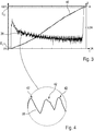
- FIG. 3 a measured current waveform 38 is shown together with the course 40 of the position of the actuator 24.
- the actuator 24 is moved from its first end position E 1 to its second end position E 2 .
- FIG. 4 an enlargement of a portion of the current waveform 38 is shown.
- Commutation artifacts 42 in the course of the current 38 which are very short rashes in the course of the current 38, can easily be recognized.
- These commutation artefacts 42 are also called "ripples".
- the commutation artefacts 42 are formed in the commutation of the DC motor 26 in that the direct current supplied to the DC motor 26 is converted by a mechanical inverter into an AC current.
- the control unit 30 recognizes the commutation artifacts 42 in the measured current profile 38 and counts the number of occurring commutation artifacts 42.
- control unit 30 has information about the polarity of the current supplied to the DC motor 26, for example about the sign of the current or through an information of the driver 32.
- the control unit 30 increments the number of detected commutation artifacts 42 by one for each detected commutation artifact 42. Similarly, the controller 30 reduces the number of commutation artifacts 42 by one if the current supplied to the DC motor 26 results in rotation in the negative direction of rotation and another commutation artifact 42 has been detected.
- control unit 30 can then close on the rotation angle and the number of completed rotations of the DC motor 26.
- control unit 30 divides the number of commutation artifacts 42 by two, thereby obtaining the number of fully completed revolutions.
- the DC motor 26 If the number of commutation artefacts 42 is odd, this means that the DC motor 26 also has a rotation angle of over 180 °. If the number of commutation artifacts 42 is even, the rotational angle of the DC motor 26 is less than 180 °.
- the number of commutation artefacts 42 and thus the number of completed rotations of the DC motor 26 including the angular position is counted starting from one of the end positions E 1 and E 2 .
- the control unit 30 can thus determine the path traveled by the actuator 24 from the end position based on the number of completed revolutions of the DC motor and the current angular position of the DC motor 26. For this purpose, the control unit 30 uses the information about the ratio of the transmission 28, which are stored in a memory of the control unit 30.
- information about the type of the actuator 24 is stored in the control unit 30, for example information about the range of motion of the actuator 24th
- the control unit 30 may determine that the control damper, ie, the actuator 24, has been rotated 9 degrees when 18 rotations have been completed by the DC motor 26.
- control unit 30 may have information about the range of motion of the actuator, so the control valve.
- the range of motion of the control flap 45 ° so that 18 completed revolutions of the DC motor 26 correspond to a 20% open control flap.
- the control unit 30 reduces the number of Kommutêtsartefakte 42 and thus the number of completed revolutions accordingly.
- the position of the actuator 24 relative to one of its end positions without further sensors, such as a position sensor for the actuator 24 can be determined.
- the control unit 30 can determine based on data of the driver 32 or the current waveform 38 when the actuator 24 reaches one of its end positions E 1 , E 2 . As in FIG. 3 to see the current rises sharply as soon as the end position E 2 of the actuator 24 is reached. This increase is recognized by the driver 32 or the control unit 30 as reaching the end position E 2 .
- control unit 30 determines that the actuator 24 has reached one of its end positions E 1 , E 2 , it sets the position determined by it of the actuator 24 to the corresponding end position E 1 , E 2 , regardless of whether the number of Commutation artifacts 42 determined position of the actuator 24 matches or not.
- the control unit 30 Before resetting the number of commutation artefacts 42 or when reaching the end position E 1 , E 2 , the control unit 30 compares the number of commutation artifacts 42 with a predetermined minimum number and / or a predetermined range, which is stored in a memory of the control unit 30 is.
- the predetermined minimum number and / or the predetermined range are calculated or empirically determined values for the number of commutation artefacts 42 which at least occur during operation of the actuator 24 from one of the end positions E 1 , E 2 in the other in error-free operation or between which Number is high probability.
- the controller 30 concludes that there is a problem with the actuator assembly 22 and generates an error message, for example.
- control unit 30 counts the number of commutation artifacts 42 away from zero, whereby an accurate determination of the position is always achieved.
- the value table can also specify the position of the actuator 24 as a function of the number of completed rotations of the DC motor 26 or the completed rotation angle.
Landscapes
- Engineering & Computer Science (AREA)
- Chemical & Material Sciences (AREA)
- Combustion & Propulsion (AREA)
- Mechanical Engineering (AREA)
- General Engineering & Computer Science (AREA)
- Control Of Position Or Direction (AREA)
- Valve Device For Special Equipments (AREA)
- Control Of Throttle Valves Provided In The Intake System Or In The Exhaust System (AREA)
Abstract
Description
- Die Erfindung betrifft ein Verfahren zur Bestimmung der Position eines Stellglieds eines Verbrennungsmotors, insbesondere einer Regelklappe, einer Drallklappe oder eines Ventils. Die Erfindung betrifft außerdem eine Stellgliedbaugruppe für einen Verbrennungsmotor mit einem Stellglied, einem Gleichstrommotor und einer Steuereinheit.
- In modernen Verbrennungsmotoren kommen eine Vielzahl an geregelten oder gesteuerten Stellgliedern zum Einsatz, die für einen optimalen Betrieb des Verbrennungsmotors in bestimmte Positionen zwischen zwei Endlagen gebracht werden müssen. Solche Stellglieder sind beispielsweise Klappen oder Ventile.
- Es ist daher notwendig, die Position des Stellglieds zu erfassen, wobei zur Erfassung der Position üblicherweise spezielle Positionssensoren, wie Hallsensoren, am Stellglied vorgesehen sind. Diese Positionssensoren führen zu erhöhten Kosten des Stellglieds, sowohl durch Material- als auch durch Montagekosten. Außerdem schränken die Positionssensoren den Temperaturbereich und die Vibrationsfestigkeit des Stellgliedes ein.
- Es ist daher Aufgabe der Erfindung, ein Verfahren zur Bestimmung der Position eines Stellglieds sowie eine Stellgliedbaugruppe bereitzustellen, die eine Bestimmung der Position des Stellglieds auf kostengünstige und gleichzeitig robuste Weise ermöglichen.
- Die Aufgabe wird gelöst durch ein Verfahren zur Bestimmung der Position eines Stellglieds eines Verbrennungsmotors, insbesondere einer Regelklappe, einer Drallklappe oder eines Ventils, das von einem Gleichstrommotor betätigt wird, mit den folgenden Schritten:
- a) Messen des Stromverlaufs des dem Gleichstrommotor zugeführten Stromes,
- b) Erkennen von Kommutierungsartefakten im gemessenen Stromverlauf,
- c) Bestimmen der Anzahl an erkannten Kommutierungsartefakten durch eine Steuereinheit,
- d) Bestimmen der Position des Stellglieds anhand der Anzahl an Kommutierungsartefakten durch die Steuereinheit.
- Eine Strommessung wird üblicherweise bei Gleichstrommotoren oder ihren Treibern bereits für andere Zwecke vorgenommen oder ist ohne aufwendige und empfindliche Sensorik, wie einem Shunt, zu realisieren.
- Die Erfindung beruht auf der Idee, dass eine Bestimmung der Position mit hinreichender Genauigkeit aus der Anzahl an Kommutierungen möglich ist. Die Genauigkeit einer Positionsermittlung anhand der Kommutierungsartefakt ist zwar geringer als bei speziellen Positionssensoren, jedoch wurde erkannt, dass die mittels Kommutierungsartefakten erzielbare Genauigkeit für viele Anwendungen im Verbrennungsmotor ausreichend ist.
- Unter Kommutierungsartefakten werden im Rahmen dieser Erfindung Ausschläge im Stromverlauf verstanden, die durch die mechanische Kommutierung des Gleichstrommotors erzeugt werden. Diese Kommutierungsartefakte werde auch "Ripples" genannt.
- Vorzugsweise bestimmt die Steuereinheit die Drehrichtung des Gleichstrommotors, insbesondere anhand der Polarität des Stromes, und zieht die Drehrichtung zur Bestimmung der Position des Stellgliedes heran.
- Zum Beispiels wird die Anzahl an Kommutierungsartefakten bei Drehung des Gleichstrommotors in positive Drehrichtung mit jedem weiteren erkannten Kommutierungsartefakt um eins erhöht und bei Drehung in negative Drehrichtung mit jedem weiteren erkannten Kommutierungsartefakt um eins verringert.
- Um den Einfluss von Messfehlern zu verringern, kann die Steuereinheit die Position des Stellgliedes unter Verwendung der Anzahl an Kommutierungsartefakten relativ zu einer Endlage des Stellgliedes bestimmt.
- Beispielsweise erkennt die Steuereinheit, wenn das Stellglied die Endlage erreicht hat, und bestimmt daraufhin unabhängig von der Anzahl der Kommutierungsartefakte die Position des Stellglieds als die Endlage. Ist eine Endlage erreicht, interpretiert die Steuereinheit die aktuelle Position als Endlage. Somit erfolgt jedes Mal, wenn das Stellglied eine seiner Endlagen erreicht hat eine Kalibrierung des Messverfahrens. Außerdem kann die Anzahl der Kommutierungsartefakte der absolvierten Umdrehungen und/oder des Drehwinkels auf Null gesetzt werden, wenn eine Endlage erreicht wird.
- In einer Ausgestaltung bestimmt die Steuereinheit die Anzahl der vom Gleichstrommotor absolvierten Umdrehungen und/oder den absolvierten Drehwinkel des Gleichstrommotors anhand der Anzahl der Kommutierungsartefakte und verwendet die die Anzahl der vom Gleichstrommotor absolvierten Umdrehungen und/oder den absolvierten Drehwinkel zur Bestimmung der Position des Stellglieds. Auf diese Weise ist eine einfache und zuverlässige Bestimmung der Position möglich.
- In einer Ausführungsform ist ein Getriebe zwischen dem Gleichstrommotor und dem Stellglied vorgesehen, wobei in der Steuereinheit Informationen über die Übersetzung des Getriebes hinterlegt sind, wobei die Steuereinheit die Position des Stellglieds in Abhängigkeit der Übersetzung des Getriebes sowie den absolvierten Umdrehungen und/oder dem absolvierten Drehwinkel des Gleichstrommotors bestimmt. Dadurch lässt sich die Position des Stellglieds auch bei der Verwendung von Getrieben bestimmten.
- Zum Beispiel ist das Getriebe selbstsperrend, um Messfehler durch unbeabsichtigte Bewegungen des Stellglieds zu vermeiden.
- In einer weiteren Ausführungsform der Erfindung ist in der Steuereinheit eine Wertetabelle hinterlegt, die die Position des Stellglieds in Abhängigkeit der Anzahl an Kommutierungsartefakten, der Anzahl an absolvierten Umdrehungen, des absolvierten Drehwinkels und/oder der Übersetzung des Getriebes angibt. Auf diese Weise lässt sich das Verfahren beschleunigen.
- Beispielsweise wird der Stromverlauf durch die Steuereinheit, einen Treiber des Gleichstrommotors oder einen Shunt mit Spannungsmesser gemessen, wodurch eine genaue Bestimmung des Stromverlaufs möglich ist.
- Ferner wird die Aufgabe gelöst durch eine Stellgliedbaugruppe für einen Verbrennungsmotor mit einem Stellglied, einem Gleichstrommotor und einer Steuereinheit, die dazu eingerichtet ist, das erfindungsgemäße Verfahren durchzuführen.
- Beispielsweise ist die Steuereinheit Teil eines Treibers und/oder einer H-Brücke für den Gleichstrommotor, wodurch die Kosten weiter reduziert werden können. Der Treiber und/oder die H-Brücke ist insbesondere Teil der Stellgliedbaugruppe.
- In einer Ausführungsvariante ist das Stellglied eine Regelklappe für eine Turboladereinheit des Verbrennungsmotors, eine Drallklappe für eine Sauganlage des Verbrennungsmotors oder ein Ventil, insbesondere ein Mehrwegeventil für einen Motorkühlkreislauf des Verbrennungsmotors. Dadurch können Stellglieder, bei denen eine exakte Kenntnis der Position nicht zu einer Verbesserung des Verbrennungsmotors führen würde, kostengünstig realisiert werden.
- Zum Beispiel dient die Regelklappe zur Umschaltung zwischen zwei Turboladern einer Turboladereinheit und die Drallklappe dient zur Veränderung des Dralls, mit dem der Kraftstoff bzw. das Kraftstoff-Luft-Gemisch in den Zylinder einbracht wird.
- Zur Bereitstellung einer Übersetzung kann die Stellgliedbaugruppe ein Getriebe mit einer vorbestimmten Übersetzung aufweisen, wobei das Getriebe insbesondere selbstsperrend ist.
- Weitere Merkmale und Vorteile der Erfindung ergeben sich aus der nachfolgenden Beschreibung sowie aus den beigefügten Zeichnungen, auf die Bezug genommen wird. In den Zeichnungen zeigen:
-
Figur 1 einen Verbrennungsmotor mit einer erfindungsgemäßen Stellgliedbaugruppe, -
Figur 2 eine erfindungsgemäße Stellgliedbaugruppe, -
Figur 3 eine Darstellung eines gemessenen Stromverlaufs während der Durchführung des erfindungsgemäßen Verfahrens, und -
Figur 4 eine Vergrößerung eines Ausschnittes aus dem Stromverlauf gemäßFigur 3 . - In
Figur 1 ist ein Verbrennungsmotor 10 mit einer Turboladereinheit 12, beispielsweise einem Bi-Turbolader, einer Sauganlage 14, einem Motorblock 16 einer Abgasanlage 18 sowie einem Motorkühlkreislauf 20 gezeigt. - Im gezeigten Ausführungsbeispiel weist die Turboladereinheit 12, die Sauganlage 14 und der Motorkühlkreislauf 20 jeweils wenigstens eine Stellgliedbaugruppe 22 auf, die jeweils ein Stellglied 24 (
Figur 2 ) umfassen. - Das Stellglied 24 der Stellgliedbaugruppe 22 der Turboladereinheit 12 ist eine Regelklappe, die den Luft- bzw. Abgasstrom zwischen zwei verschiedenen Turboladern der Turboladereinheit 12 zuführen kann.
- In der Sauganlage 14 ist eine Stellgliedbaugruppe 22 mit vier Drallklappen als Stellglieder 24 vorgesehen. Die Drallklappen können die Einströmrichtung eines Brennstoff-Luftgemisches in die Zylinder des Motorblocks und damit den Drall, der sich im entsprechenden Zylinder ausbildet, verändern. Die vier Drallklappen werden über eine Stange 21 mit dem Gleichstrommotor 26 verbunden und betätigt.
- Das Stellglied 24 der Stellgliedbaugruppe 22 des Motorkühlkreislaufs 20 ist ein Ventil, insbesondere ein Mehrwegventil, das den Kühlmittelfluss in verschiedene Zweige des Motorkühlkreislauf 20 kontrolliert.
- Selbstverständlich lassen sich auch weitere Stellglieder als Teil einer erfindungsgemäßen Stellgliedbaugruppe 22 ausbilden. Die beschriebenen Anwendungsfälle sind lediglich beispielhaft zu verstehen.
- In
Figur 2 ist eine der Stellgliedbaugruppen 22 sehr schematisch dargestellt. - Die Stellgliedbaugruppe 22 weist neben dem Stellglied 24 einen Gleichstrommotor 26 und ein Getriebe 28 sowie eine Steuereinheit 30 und einen Treiber 32 auf. Der Gleichstrommotor 26, genauer gesagt die Ausgangswelle des Gleichstrommotors 26 ist zur Drehmomentübertragung über das Getriebe 28 mit dem Stellglied 24 verbunden.
- Das Getriebe 28 hat eine bekannte Übersetzung und ist beispielsweise ein Schneckengetriebe.
- Das Getriebe 28 ist insbesondere selbstsperrend, sodass seine Position nur durch den Gleichstrommotor 26 verändert werden kann.
- Der Gleichstrommotor 26 ist über zwei Stromleitungen 34 mit dem Treiber 32 verbunden, der dem Gleichstrommotor 26 Strom zuführen kann. Der Treiber 32 kann eine H-Brücke 33 aufweisen.
- Der Treiber 32 ist mit der Steuereinheit 30 elektrisch verbunden, sodass die Steuereinheit 30 den Treiber 32 ansteuern kann.
- Selbstverständlich kann die Steuereinheit 30 auch im Treiber 32 integriert sein.
- In
Figur 2 ist zudem zur Strommessung durch die Stromleitungen 34 ein Shunt 36 mitsamt Spannungsmesser vorgesehen, die zusammen dargestellt sind. Der Spannungsmesser ist mit der Steuereinheit 30 elektrisch verbunden. - Zum Betätigen des Stellglieds 24 weist die Steuereinheit 30 den Treiber 32 an, den Gleichstrommotor 26 zu bestromen, d. h. Strom zuzuführen.
- Der Gleichstrommotor 26 setzt die ihm zugeführte elektrische Energie in ein Drehmoment bzw. eine Rotation seiner Ausgangswelle um. Das Drehmoment wird vom Getriebe 28 übersetzt und dem Stellglied 24 zugeführt, wodurch das Stellglied 24 betätigt wird.
- Im gezeigten Ausführungsbeispiel wird auf diese Weise beispielsweise das Mehrwegventil im Motorkühlkreislauf 20 geöffnet, die Regelklappe der Turboladereinheit 12 oder eine Drallklappe der Sauganlage 14 bewegt.
- Das Stellglied 24 kann vom Gleichstrommotor 26 zwischen zwei Endlagen bewegt werden. Die Bewegungsrichtung des Stellglieds 24 hängt dabei von der Drehrichtung des Gleichstrommotors 26 ab. Genauer gesagt hängt die Drehrichtung des Stellgliedes 24 von der Drehrichtung der Ausgangswelle des Gleichstrommotors 26 ab. Im Folgenden wird jedoch zur Vereinfachung lediglich vom Gleichstrommotor 26 gesprochen.
- In Abhängigkeit der Polarität des dem Gleichstrommotor 26 zugeführten Stroms wird der Gleichstrommotor 26 bzw. seine Ausgangswelle in eine positive bzw. negative Drehrichtung verdreht, wodurch das Stellglied 24 in eine positive bzw. negative Richtung verstellt wird.
- Der vom Stellglied 24 zurückgelegte Weg ist dabei abhängig von der Anzahl der Umdrehungen des Gleichstrommotors 26 und der Übersetzung des Getriebes 28, sodass die Stellung des Stellgliedes 24 anhand der Anzahl an Umdrehungen, die der Gleichstrommotor 26 absolviert hat, und der Übersetzung des Getriebes 28 bestimmt werden kann.
- Zur Bestimmung der vom Gleichstrommotor 26 absolvierten Umdrehungen und damit der Position des Stellgliedes 24 ermittelt die Steuereinheit 30 den Stromverlauf 38 des Stroms, der dem Gleichstrommotor 26 vom Treiber 32 zugeführt wurde.
- Die Messung des Stroms kann dabei durch den Treiber 32 selbst erfolgen, beispielsweise bestimmt der Treiber 32 ohnehin selbst den sogenannten Stromspiegel. Die Messung kann auch in der H-Brücke 33 erfolgen.
- Eine genauere Messung des Stroms kann mittels des Shunts 36 erfolgen, wobei die Strommessung dann von der Steuereinheit 30 selbst durchgeführt wird.
- In
Figur 3 ist ein gemessener Stromverlauf 38 zusammen mit dem Verlauf 40 der Position des Stellglieds 24 dargestellt. - Im gezeigten Beispiel wird das Stellglied 24 von seiner ersten Endlage E1 zu seiner zweiten Endlage E2 bewegt.
- In
Figur 4 ist eine Vergrößerung eines Abschnittes des Stromverlaufs 38 dargestellt. Gut zu erkennen sind Kommutierungsartefakte 42 im Stromverlauf 38, die sehr kurze Ausschläge im Stromverlauf 38 sind. Diese Kommutierungsartefakte 42 werden auch "Ripples" genannt. - Die Kommutierungsartefakte 42 entstehen bei der Kommutierung des Gleichstrommotors 26 dadurch, dass der dem Gleichstrommotor 26 zugeführte Gleichstrom durch einen mechanischen Wechselrichter in einen Wechselstrom umgewandelt wird.
- Bei der Umpolung des Wechselstroms entstehen kurzzeitige Ausschläge im zugeführten Gleichstrom, die charakteristisch und daher gut zu erkennen sind.
- In Abhängigkeit der Bauweise des Gleichstrommotors 26 findet eine bestimmte Anzahl an Kommutierungen pro vollständiger Umdrehung des Gleichstrommotors 26 statt, sodass pro vollständiger Umdrehung des Gleichstrommotors 26 eine bestimmte Anzahl an Kommutierungsartefakten 42 erzeugt wird.
- Im einfachsten Fall eines Gleichstrommotors 26 finden zwei Kommutationen pro vollständiger Umdrehung des Gleichstrommotors 26 statt, sodass jedes Kommutierungsartefakt 42 einer halben Umdrehung des Gleichstrommotors 26 entspricht. Zur Erläuterung wird im Folgenden beispielhaft von einem solchen Gleichstrommotor mit zwei Kommutierungen ausgegangen. Zwischen zwei Kommutierungsartefakten hat sich der Gleichstrommotor 26 um 180° weitergedreht.
- Die Steuereinheit 30 erkennt die Kommutierungsartefakte 42 im gemessenen Stromverlauf 38 und zählt die Anzahl der auftretenden Kommutierungsartefakte 42.
- Gleichzeitig hat die Steuereinheit 30 Informationen zur Polarität des dem Gleichstrommotor 26 zugeführten Stromes, beispielsweise über das Vorzeichen des Stroms oder durch eine Information des Treibers 32.
- Führt der dem Gleichstrommotor 26 zugeführte Strom zu einer Drehung des Gleichstrommotors bzw. seiner Ausgangswelle in die positive Drehrichtung, erhöht die Steuereinheit 30 bei jedem erkannten Kommutierungsartefakt 42 die Anzahl der erfassten Kommutierungsartefakte 42 um eins. Gleichermaßen verringert die Steuereinheit 30 die Anzahl der Kommutierungsartefakte 42 um eins, falls der dem Gleichstrommotor 26 zugeführte Strom zu einer Drehung in die negative Drehrichtung führt und ein weiteres Kommutierungsartefakt 42 erkannt wurde.
- Aus der Anzahl an Kommutierungsartefakten 42 und der Information über den Aufbau des Gleichstrommotors 26 kann die Steuereinheit 30 dann auf den Drehwinkel und die Anzahl der absolvierten Umdrehungen des Gleichstrommotors 26 schließen.
- Im diskutierten Fall teilt die Steuereinheit 30 die Anzahl der Kommutierungsartefakte 42 durch zwei und erhält dadurch die Anzahl an vollständig absolvierten Umdrehungen.
- Falls die Anzahl an Kommutierungsartefakten 42 ungerade ist, bedeutet dies, dass der Gleichstrommotor 26 zudem einen Drehwinkel von über 180° hat. Falls die Anzahl der Kommutierungsartefakte 42 gerade ist, liegt der Drehwinkel des Gleichstrommotors 26 bei weniger als 180°.
- Die Anzahl an Kommutierungsartefakten 42 und damit die Anzahl an absolvierten Umdrehungen des Gleichstrommotors 26 inklusive der Winkellage wird ausgehend von einer der Endlagen E1 bzw. E2 gezählt.
- Die Steuereinheit 30 kann also anhand der Anzahl an absolvierten Umdrehungen des Gleichstrommotors und der aktuellen Winkellage des Gleichstrommotors 26 den vom Stellglied 24 zurückgelegten Weg aus der Endposition ermitteln. Hierzu verwendet die Steuereinheit 30 die Informationen über die Übersetzung des Getriebes 28, die in einem Speicher der Steuereinheit 30 hinterlegt sind.
- Zudem sind in der Steuereinheit 30 Informationen zur Art des Stellglieds 24 hinterlegt, beispielsweise Informationen über den Bewegungsumfang des Stellglieds 24.
- Beispielsweise entspricht aufgrund der Übersetzung des Getriebes 28 eine vollständige Umdrehung des Gleichstrommotors 26 einer Rotation der Regelklappe der Turboladereinheit 12 um 0,5°. Somit kann die Steuereinheit 30 bestimmen, dass die Regelklappe, also das Stellglied 24, um 9° gedreht wurde, wenn 18 Umdrehungen vom Gleichstrommotor 26 absolviert wurden.
- Außerdem kann die Steuereinheit 30 Informationen über den Bewegungsumfang des Stellglieds, also der Regelklappe haben. Beispielsweise beträgt der Bewegungsumfang der Regelklappe 45°, sodass 18 absolvierte Umdrehungen des Gleichstrommotors 26 einer um 20 % geöffneten Regelklappe entsprechen.
- Wird der Gleichstrommotor 26 in die entgegengesetzte Drehrichtung verdreht, verringert die Steuereinheit 30 die Anzahl der Kommutierungsartefakte 42 und damit die Anzahl der absolvierten Umdrehungen entsprechend.
- Auf diese Weise kann die Position des Stellgliedes 24 relativ zu einer seiner Endlagen ohne weitere Sensorik, wie einem Positionssensor für das Stellglied 24 ermittelt werden.
- Die Steuereinheit 30 kann anhand von Daten des Treibers 32 oder des Stromverlaufs 38 bestimmen, wenn das Stellglied 24 eine seiner Endlagen E1, E2 erreicht. Wie in
Figur 3 zu sehen, steigt der Strom stark an, sobald die Endlage E2 des Stellglieds 24 erreicht ist. Dieser Anstieg wird vom Treiber 32 oder der Steuereinheit 30 als Erreichen der Endlage E2 erkannt. - Sobald die Steuereinheit 30 ermittelt, dass das Stellglied 24 eine seiner Endlagen E1, E2 erreicht hat, setzt sie die von ihr bestimmte Position des Stellglieds 24 auf die entsprechende Endlage E1, E2, unabhängig davon, ob die mithilfe der Anzahl der Kommutierungsartefakte 42 ermittelte Position des Stellglieds 24 damit übereinstimmt oder nicht.
- Außerdem setzt sie die Anzahl der Kommutierungsartefakte 42 und auch der absolvierten Umdrehungen des Gleichstrommotors 26 auf Null zurück, wodurch das Verfahren zur Positionsbestimmung kalibriert wird.
- Vor dem Zurücksetzen der Anzahl der Kommutierungsartefakte 42 bzw. beim Erreichen der Endlage E1, E2 vergleicht die Steuereinheit 30 die Anzahl der Kommutierungsartefakte 42 mit einer vorbestimmten Mindestanzahl und/oder einem vorbestimmten Bereich, die bzw. der in einem Speicher der Steuereinheit 30 hinterlegt ist.
- Die vorbestimmte Mindestanzahl und/oder der vorbestimmte Bereich sind berechnete oder empirisch ermittelte Werte für die Anzahl an Kommutierungsartefakten 42, die beim Betätigen des Stellglieds 24 von einer der Endlagen E1, E2 in die andere im fehlerfreien Betrieb wenigstens auftreten bzw. zwischen denen die Anzahl mit hoher Wahrscheinlichkeit liegt.
- Durch den Vergleich wird geprüft, ob es plausibel ist, dass die Endlage E1, E2 erreicht wurde.
- Liegt die Anzahl der Kommutierungsartefakte 42 unterhalb der vorbestimmten Mindestanzahl und/oder außerhalb des vorbestimmten Bereiches, schließt die Steuereinheit 30 darauf, dass ein Problem mit der Stellgliedbaugruppe 22 vorliegt und erzeugt beispielsweise eine Fehlermeldung.
- Wird das Stellglied 24 anschließend aus der Endlage E2 herausbewegt, so zählt die Steuereinheit 30 die Anzahl der Kommutierungsartefakte 42 von Null weg, wodurch stets eine genaue Bestimmung der Position erreicht wird.
- Denkbar ist selbstverständlich auch, dass in der Steuereinheit 30 eine Wertetabelle hinterlegt ist, die die Position des Stellglieds 24 direkt mit der Anzahl der Kommutierungsartefakte 42 verknüpft, ohne dass die Steuereinheit 30 Berechnungen zur Anzahl der absolvierten Umdrehungen des Gleichstrommotors 26 oder der Übersetzung des Getriebes 28 vornehmen muss.
- Selbstverständlich kann die Wertetabelle auch die Position des Stellglieds 24 in Abhängigkeit der Anzahl der absolvierten Umdrehungen des Gleichstrommotors 26 oder des absolvierten Drehwinkels angeben.
Claims (13)
- Verfahren zur Bestimmung der Position eines Stellglieds (24) eines Verbrennungsmotors (10), insbesondere einer Regelklappe, einer Drallklappe oder eines Ventils, das von einem Gleichstrommotor (26) betätigt wird, mit den folgenden Schritten:a) Messen des Stromverlaufs (38) des dem Gleichstrommotor (26) zugeführten Stromes,b) Erkennen von Kommutierungsartefakten (42) im gemessenen Stromverlauf (38),c) Bestimmen der Anzahl an erkannten Kommutierungsartefakten (42) durch eine Steuereinheit (30),d) Bestimmen der Position des Stellglieds (24) anhand der Anzahl an Kommutierungsartefakten (42) durch die Steuereinheit (30).
- Verfahren nach Anspruch 1, dadurch gekennzeichnet, dass die Steuereinheit (30) die Drehrichtung des Gleichstrommotors (26) bestimmt, insbesondere anhand der Polarität des Stromes, und zur Bestimmung der Position des Stellgliedes (24) heranzieht.
- Verfahren nach Anspruch 1 oder 2, dadurch gekennzeichnet, dass die Steuereinheit (30) die Position des Stellgliedes (24) unter Verwendung der Anzahl an Kommutierungsartefakten (42) relativ zu einer Endlage (E1, E2) des Stellgliedes (24) bestimmt.
- Verfahren nach Anspruch 3, dadurch gekennzeichnet, dass die Steuereinheit (30) erkennt, wenn das Stellglied (24) die Endlage (E1, E2) erreicht hat, und daraufhin unabhängig von der Anzahl der Kommutierungsartefakte (42) die Position des Stellglieds (24) als die Endlage (E1, E2) bestimmt.
- Verfahren nach Anspruch 4, dadurch gekennzeichnet, dass die Steuereinheit (30) beim Erreichen der Endlage (E1, E2) überprüft, ob die Anzahl der Kommutierungsartefakte (42) oberhalb einer vorbestimmten Mindestanzahl und/oder innerhalb eines vorbestimmten Bereichs liegt.
- Verfahren nach einem der vorhergehenden Ansprüche, dadurch gekennzeichnet, dass die Steuereinheit (30) die Anzahl der vom Gleichstrommotor (26) absolvierten Umdrehungen und/oder den absolvierten Drehwinkel des Gleichstrommotors (26) anhand der Anzahl der Kommutierungsartefakte (42) bestimmt und zur Bestimmung der Position des Stellglieds (24) verwendet.
- Verfahren nach Anspruch 6, dadurch gekennzeichnet, dass ein Getriebe (28) zwischen dem Gleichstrommotor (26) und dem Stellglied (24) vorgesehen ist, wobei in der Steuereinheit (30) Informationen über die Übersetzung des Getriebes (28) hinterlegt sind, wobei die Steuereinheit (30) die Position des Stellglieds (24) in Abhängigkeit der Übersetzung des Getriebes (28) sowie den absolvierten Umdrehungen und/oder dem absolvierten Drehwinkel des Gleichstrommotors (26) bestimmt.
- Verfahren nach einem der vorhergehenden Ansprüche, dadurch gekennzeichnet, dass in der Steuereinheit (30) eine Wertetabelle hinterlegt ist, die die Position des Stellglieds (24) in Abhängigkeit der Anzahl an Kommutierungsartefakten, der Anzahl an absolvierten Umdrehungen, des absolvierten Drehwinkels und/oder der Übersetzung des Getriebes (28) angibt.
- Verfahren nach einem der vorhergehenden Ansprüche, dadurch gekennzeichnet, dass der Stromverlauf (38) durch die Steuereinheit (30), einen Treiber (32) des Gleichstrommotors (26) oder einen Shunt (36) mit Spannungsmesser gemessen wird.
- Stellgliedbaugruppe für einen Verbrennungsmotor mit einem Stellglied (24), einem Gleichstrommotor (26) und einer Steuereinheit (30), die dazu eingerichtet ist, ein Verfahren gemäß einem der vorhergehenden Ansprüche durchzuführen.
- Stellgliedbaugruppe nach Anspruch 10, dadurch gekennzeichnet, dass die Steuereinheit (30) Teil eines Treibers (32) und/oder einer H-Brücke für den Gleichstrommotor (26) ist.
- Stellgliedbaugruppe nach Anspruch 10 oder 11, dadurch gekennzeichnet, dass das Stellglied (24) eine Regelklappe für eine Turboladereinheit (12) des Verbrennungsmotors (10), eine Drallklappe für eine Sauganlage (14) des Verbrennungsmotors (10) oder ein Ventil, insbesondere ein Mehrwegeventil für einen Motorkühlkreislauf (20) des Verbrennungsmotors (10) ist.
- Stellgliedbaugruppe nach einem der Ansprüche 10 bis 12, dadurch gekennzeichnet, dass die Stellgliedbaugruppe (22) ein Getriebe (28) mit einer vorbestimmten Übersetzung aufweist, wobei das Getriebe (28) insbesondere selbstsperrend ist.
Applications Claiming Priority (1)
| Application Number | Priority Date | Filing Date | Title |
|---|---|---|---|
| DE102018201513.9A DE102018201513A1 (de) | 2018-02-01 | 2018-02-01 | Verfahren zur Bestimmung der Position eines Stellglieds sowie Stellgliedbaugruppe |
Publications (2)
| Publication Number | Publication Date |
|---|---|
| EP3521598A1 true EP3521598A1 (de) | 2019-08-07 |
| EP3521598B1 EP3521598B1 (de) | 2020-09-09 |
Family
ID=65199348
Family Applications (1)
| Application Number | Title | Priority Date | Filing Date |
|---|---|---|---|
| EP19152966.8A Active EP3521598B1 (de) | 2018-02-01 | 2019-01-22 | Verfahren zur bestimmung der position eines stellglieds sowie stellgliedbaugruppe |
Country Status (2)
| Country | Link |
|---|---|
| EP (1) | EP3521598B1 (de) |
| DE (1) | DE102018201513A1 (de) |
Families Citing this family (1)
| Publication number | Priority date | Publication date | Assignee | Title |
|---|---|---|---|---|
| CH718623A2 (de) * | 2021-05-12 | 2022-11-15 | Oblamatik Ag | Verstelleinrichtung, motorisch angetriebenes Ventil und Verfahren zum Betreiben einer Verstelleinrichtung. |
Citations (10)
| Publication number | Priority date | Publication date | Assignee | Title |
|---|---|---|---|---|
| US5132602A (en) * | 1990-10-02 | 1992-07-21 | Calsonic International, Inc. | Actuator positioning apparatus |
| EP0697305A1 (de) * | 1994-08-03 | 1996-02-21 | The Cherry Corporation | Intelligentes Detektorsystem für Kommutationspulse zur Steuerung von in Kraftwagenzusatzgeräten verwendeten elektrischen Gleichstrommotoren |
| EP1381148A2 (de) * | 2002-07-11 | 2004-01-14 | Robert Bosch Gmbh | Hochauflösende Drehwinkelsensorik für Gleichstrommotoren |
| EP1679777A1 (de) * | 2005-01-05 | 2006-07-12 | Behr-Hella Thermocontrol GmbH | Vorrichtung zur Defekterkennung bei einem Kollektor-Gleichstrommotor basierend auf der Welligkeit des Ankerstroms |
| WO2007017483A1 (de) * | 2005-08-09 | 2007-02-15 | Siemens Aktiengesellschaft | Elektronische schaltung |
| EP1903668A2 (de) * | 2006-09-20 | 2008-03-26 | Behr-Hella Thermocontrol GmbH | Verfahren zur Ermittlung der Drehposition des Ankers eines Gleichstrommotors mit Kommutator |
| DE102008002724A1 (de) * | 2008-06-27 | 2009-12-31 | Robert Bosch Gmbh | Verfahren zur Erkennung des Drehwinkels und einer Reversierposition einer Getriebe-Antriebseinheit |
| WO2010028736A2 (de) * | 2008-09-12 | 2010-03-18 | Brose Fahrzeugteile Gmbh & Co. Kommanditgesellschaft, Hallstadt | Verfahren und vorrichtung zur verarbeitung eines stromrippel aufweisenden motorsignals eines gleichstrommotors |
| WO2010105795A2 (de) * | 2009-03-16 | 2010-09-23 | Brose Fahrzeugteile Gmbh & Co. Kommanditgesellschaft Hallstadt | Korrektur von zählfehlern bei der auswertung von stromrippeln bei einem gleichstrommotor |
| EP2561608A2 (de) * | 2010-04-22 | 2013-02-27 | Brose Fahrzeugteile GmbH & Co. Kommanditgesellschaft, Hallstadt | Verarbeitung einer motorgrösse eines gleichstrommotors |
-
2018
- 2018-02-01 DE DE102018201513.9A patent/DE102018201513A1/de not_active Withdrawn
-
2019
- 2019-01-22 EP EP19152966.8A patent/EP3521598B1/de active Active
Patent Citations (10)
| Publication number | Priority date | Publication date | Assignee | Title |
|---|---|---|---|---|
| US5132602A (en) * | 1990-10-02 | 1992-07-21 | Calsonic International, Inc. | Actuator positioning apparatus |
| EP0697305A1 (de) * | 1994-08-03 | 1996-02-21 | The Cherry Corporation | Intelligentes Detektorsystem für Kommutationspulse zur Steuerung von in Kraftwagenzusatzgeräten verwendeten elektrischen Gleichstrommotoren |
| EP1381148A2 (de) * | 2002-07-11 | 2004-01-14 | Robert Bosch Gmbh | Hochauflösende Drehwinkelsensorik für Gleichstrommotoren |
| EP1679777A1 (de) * | 2005-01-05 | 2006-07-12 | Behr-Hella Thermocontrol GmbH | Vorrichtung zur Defekterkennung bei einem Kollektor-Gleichstrommotor basierend auf der Welligkeit des Ankerstroms |
| WO2007017483A1 (de) * | 2005-08-09 | 2007-02-15 | Siemens Aktiengesellschaft | Elektronische schaltung |
| EP1903668A2 (de) * | 2006-09-20 | 2008-03-26 | Behr-Hella Thermocontrol GmbH | Verfahren zur Ermittlung der Drehposition des Ankers eines Gleichstrommotors mit Kommutator |
| DE102008002724A1 (de) * | 2008-06-27 | 2009-12-31 | Robert Bosch Gmbh | Verfahren zur Erkennung des Drehwinkels und einer Reversierposition einer Getriebe-Antriebseinheit |
| WO2010028736A2 (de) * | 2008-09-12 | 2010-03-18 | Brose Fahrzeugteile Gmbh & Co. Kommanditgesellschaft, Hallstadt | Verfahren und vorrichtung zur verarbeitung eines stromrippel aufweisenden motorsignals eines gleichstrommotors |
| WO2010105795A2 (de) * | 2009-03-16 | 2010-09-23 | Brose Fahrzeugteile Gmbh & Co. Kommanditgesellschaft Hallstadt | Korrektur von zählfehlern bei der auswertung von stromrippeln bei einem gleichstrommotor |
| EP2561608A2 (de) * | 2010-04-22 | 2013-02-27 | Brose Fahrzeugteile GmbH & Co. Kommanditgesellschaft, Hallstadt | Verarbeitung einer motorgrösse eines gleichstrommotors |
Also Published As
| Publication number | Publication date |
|---|---|
| EP3521598B1 (de) | 2020-09-09 |
| DE102018201513A1 (de) | 2019-08-01 |
Similar Documents
| Publication | Publication Date | Title |
|---|---|---|
| DE10130471B4 (de) | Verfahren zur Steuerung eines Abgasrückführsystems | |
| EP1194687A1 (de) | Verfahren zur korrektur eines winkelfehlers eines absolutwinkelgebers | |
| DE102010063326A1 (de) | Verfahren und Vorrichtung zum Betreiben eines Stellgebers mit einem bürstenlosen Elektromotor | |
| EP3721175B1 (de) | Sensorsystem zur bestimmung mindestens einer rotationseigenschaft eines um mindestens eine rotationsachse rotierenden elements | |
| DE102020115906A1 (de) | Hinterachslenkungsaktuator und Verfahren zur Ermittlung einer vorbestimmten Position der Schubstange eines Hinterachslenkungsaktuators | |
| DE102017125596A1 (de) | Übereinstimmungserklärung liegt vor.VERFAHREN ZUR BESTIMMUNG EINER EIGENSCHAFT EINES STELLGLIEDS | |
| EP3129793A1 (de) | Diagnose eines antriebssystems sowie antriebssystem | |
| EP2686537B1 (de) | Verfahren und vorrichtung zum kalibrieren eines stellgebersystems mit einem elektronisch kommutierten stellantrieb | |
| WO2006111144A1 (de) | Verfahren zur sensorlosen positionserfassung eines rotors eines elektromotors | |
| EP3521598A1 (de) | Verfahren zur bestimmung der position eines stellglieds sowie stellgliedbaugruppe | |
| DE3608555A1 (de) | Verfahren zur strombegrenzung eines elektromotors | |
| DE102009002859B4 (de) | Verfahren und Vorrichtung zur Diagnose eines Stellgebers | |
| DE112017004449T5 (de) | Winkelerfassungsmechanismus und Winkelerfassunssystem | |
| EP3008813A2 (de) | Verfahren und vorrichtung zum betreiben eines elektronisch kommutierten stellmotors sowie stellgebersystem mit einem stellmotor | |
| DE102016209366A1 (de) | Verfahren und Vorrichtung zur Kalibrierung eines Stellgebersystems | |
| DE102013216690A1 (de) | Ventilvorrichtung und herstellungsverfahren hierfür | |
| EP3938755B1 (de) | Verfahren und regelungseinrichtung zur regelung einer drehzahl | |
| DE102023202233A1 (de) | Ventilsteuerung für einen Kältemittelkreislauf | |
| DE4009922C2 (de) | Verfahren und Anordnung zur Ermittlung der tatsächlichen Luftdichte des Ansaug-Luftmassenstroms einer Brennkraftmaschine | |
| EP2865090B1 (de) | Verfahren und vorrichtung zur plausibilisierung einer stellung eines stellglieds eines stellgebersystems mit einer elektronisch kommutierten elektrischen maschine | |
| DE102016206714A1 (de) | Verfahren zum Ermitteln einer absoluten Winkellage einer rotierenden Welle | |
| DE102020003873A1 (de) | Verfahren zum Kompensieren einer Abweichung einer Ist-Lage von einer Soll-Lage wenigstens eines Sensors | |
| DE10339405B3 (de) | Verfahren zum Erstellen einer Sensorkennlinie | |
| DE4304633A1 (de) | Einrichtung zur elektrischen Steuerung einer Drosselklappe einer Brennkraftmaschine | |
| AT527925B1 (de) | Prüf- und Messsystem und Messaufbau |
Legal Events
| Date | Code | Title | Description |
|---|---|---|---|
| PUAI | Public reference made under article 153(3) epc to a published international application that has entered the european phase |
Free format text: ORIGINAL CODE: 0009012 |
|
| STAA | Information on the status of an ep patent application or granted ep patent |
Free format text: STATUS: THE APPLICATION HAS BEEN PUBLISHED |
|
| AK | Designated contracting states |
Kind code of ref document: A1 Designated state(s): AL AT BE BG CH CY CZ DE DK EE ES FI FR GB GR HR HU IE IS IT LI LT LU LV MC MK MT NL NO PL PT RO RS SE SI SK SM TR |
|
| AX | Request for extension of the european patent |
Extension state: BA ME |
|
| STAA | Information on the status of an ep patent application or granted ep patent |
Free format text: STATUS: REQUEST FOR EXAMINATION WAS MADE |
|
| 17P | Request for examination filed |
Effective date: 20191030 |
|
| RBV | Designated contracting states (corrected) |
Designated state(s): AL AT BE BG CH CY CZ DE DK EE ES FI FR GB GR HR HU IE IS IT LI LT LU LV MC MK MT NL NO PL PT RO RS SE SI SK SM TR |
|
| RIC1 | Information provided on ipc code assigned before grant |
Ipc: F02D 41/20 20060101AFI20200409BHEP |
|
| GRAP | Despatch of communication of intention to grant a patent |
Free format text: ORIGINAL CODE: EPIDOSNIGR1 |
|
| STAA | Information on the status of an ep patent application or granted ep patent |
Free format text: STATUS: GRANT OF PATENT IS INTENDED |
|
| INTG | Intention to grant announced |
Effective date: 20200528 |
|
| GRAS | Grant fee paid |
Free format text: ORIGINAL CODE: EPIDOSNIGR3 |
|
| GRAA | (expected) grant |
Free format text: ORIGINAL CODE: 0009210 |
|
| STAA | Information on the status of an ep patent application or granted ep patent |
Free format text: STATUS: THE PATENT HAS BEEN GRANTED |
|
| AK | Designated contracting states |
Kind code of ref document: B1 Designated state(s): AL AT BE BG CH CY CZ DE DK EE ES FI FR GB GR HR HU IE IS IT LI LT LU LV MC MK MT NL NO PL PT RO RS SE SI SK SM TR |
|
| REG | Reference to a national code |
Ref country code: GB Ref legal event code: FG4D Free format text: NOT ENGLISH |
|
| REG | Reference to a national code |
Ref country code: AT Ref legal event code: REF Ref document number: 1311868 Country of ref document: AT Kind code of ref document: T Effective date: 20200915 Ref country code: CH Ref legal event code: EP |
|
| REG | Reference to a national code |
Ref country code: IE Ref legal event code: FG4D Free format text: LANGUAGE OF EP DOCUMENT: GERMAN |
|
| REG | Reference to a national code |
Ref country code: DE Ref legal event code: R096 Ref document number: 502019000184 Country of ref document: DE |
|
| REG | Reference to a national code |
Ref country code: LT Ref legal event code: MG4D |
|
| PG25 | Lapsed in a contracting state [announced via postgrant information from national office to epo] |
Ref country code: SE Free format text: LAPSE BECAUSE OF FAILURE TO SUBMIT A TRANSLATION OF THE DESCRIPTION OR TO PAY THE FEE WITHIN THE PRESCRIBED TIME-LIMIT Effective date: 20200909 Ref country code: LT Free format text: LAPSE BECAUSE OF FAILURE TO SUBMIT A TRANSLATION OF THE DESCRIPTION OR TO PAY THE FEE WITHIN THE PRESCRIBED TIME-LIMIT Effective date: 20200909 Ref country code: BG Free format text: LAPSE BECAUSE OF FAILURE TO SUBMIT A TRANSLATION OF THE DESCRIPTION OR TO PAY THE FEE WITHIN THE PRESCRIBED TIME-LIMIT Effective date: 20201209 Ref country code: NO Free format text: LAPSE BECAUSE OF FAILURE TO SUBMIT A TRANSLATION OF THE DESCRIPTION OR TO PAY THE FEE WITHIN THE PRESCRIBED TIME-LIMIT Effective date: 20201209 Ref country code: FI Free format text: LAPSE BECAUSE OF FAILURE TO SUBMIT A TRANSLATION OF THE DESCRIPTION OR TO PAY THE FEE WITHIN THE PRESCRIBED TIME-LIMIT Effective date: 20200909 Ref country code: GR Free format text: LAPSE BECAUSE OF FAILURE TO SUBMIT A TRANSLATION OF THE DESCRIPTION OR TO PAY THE FEE WITHIN THE PRESCRIBED TIME-LIMIT Effective date: 20201210 Ref country code: HR Free format text: LAPSE BECAUSE OF FAILURE TO SUBMIT A TRANSLATION OF THE DESCRIPTION OR TO PAY THE FEE WITHIN THE PRESCRIBED TIME-LIMIT Effective date: 20200909 |
|
| REG | Reference to a national code |
Ref country code: NL Ref legal event code: MP Effective date: 20200909 |
|
| PG25 | Lapsed in a contracting state [announced via postgrant information from national office to epo] |
Ref country code: LV Free format text: LAPSE BECAUSE OF FAILURE TO SUBMIT A TRANSLATION OF THE DESCRIPTION OR TO PAY THE FEE WITHIN THE PRESCRIBED TIME-LIMIT Effective date: 20200909 Ref country code: RS Free format text: LAPSE BECAUSE OF FAILURE TO SUBMIT A TRANSLATION OF THE DESCRIPTION OR TO PAY THE FEE WITHIN THE PRESCRIBED TIME-LIMIT Effective date: 20200909 Ref country code: PL Free format text: LAPSE BECAUSE OF FAILURE TO SUBMIT A TRANSLATION OF THE DESCRIPTION OR TO PAY THE FEE WITHIN THE PRESCRIBED TIME-LIMIT Effective date: 20200909 |
|
| PG25 | Lapsed in a contracting state [announced via postgrant information from national office to epo] |
Ref country code: EE Free format text: LAPSE BECAUSE OF FAILURE TO SUBMIT A TRANSLATION OF THE DESCRIPTION OR TO PAY THE FEE WITHIN THE PRESCRIBED TIME-LIMIT Effective date: 20200909 Ref country code: RO Free format text: LAPSE BECAUSE OF FAILURE TO SUBMIT A TRANSLATION OF THE DESCRIPTION OR TO PAY THE FEE WITHIN THE PRESCRIBED TIME-LIMIT Effective date: 20200909 Ref country code: PT Free format text: LAPSE BECAUSE OF FAILURE TO SUBMIT A TRANSLATION OF THE DESCRIPTION OR TO PAY THE FEE WITHIN THE PRESCRIBED TIME-LIMIT Effective date: 20210111 Ref country code: CZ Free format text: LAPSE BECAUSE OF FAILURE TO SUBMIT A TRANSLATION OF THE DESCRIPTION OR TO PAY THE FEE WITHIN THE PRESCRIBED TIME-LIMIT Effective date: 20200909 Ref country code: SM Free format text: LAPSE BECAUSE OF FAILURE TO SUBMIT A TRANSLATION OF THE DESCRIPTION OR TO PAY THE FEE WITHIN THE PRESCRIBED TIME-LIMIT Effective date: 20200909 |
|
| PG25 | Lapsed in a contracting state [announced via postgrant information from national office to epo] |
Ref country code: IS Free format text: LAPSE BECAUSE OF FAILURE TO SUBMIT A TRANSLATION OF THE DESCRIPTION OR TO PAY THE FEE WITHIN THE PRESCRIBED TIME-LIMIT Effective date: 20210109 Ref country code: AL Free format text: LAPSE BECAUSE OF FAILURE TO SUBMIT A TRANSLATION OF THE DESCRIPTION OR TO PAY THE FEE WITHIN THE PRESCRIBED TIME-LIMIT Effective date: 20200909 Ref country code: ES Free format text: LAPSE BECAUSE OF FAILURE TO SUBMIT A TRANSLATION OF THE DESCRIPTION OR TO PAY THE FEE WITHIN THE PRESCRIBED TIME-LIMIT Effective date: 20200909 |
|
| REG | Reference to a national code |
Ref country code: DE Ref legal event code: R097 Ref document number: 502019000184 Country of ref document: DE |
|
| PG25 | Lapsed in a contracting state [announced via postgrant information from national office to epo] |
Ref country code: SK Free format text: LAPSE BECAUSE OF FAILURE TO SUBMIT A TRANSLATION OF THE DESCRIPTION OR TO PAY THE FEE WITHIN THE PRESCRIBED TIME-LIMIT Effective date: 20200909 |
|
| PLBE | No opposition filed within time limit |
Free format text: ORIGINAL CODE: 0009261 |
|
| STAA | Information on the status of an ep patent application or granted ep patent |
Free format text: STATUS: NO OPPOSITION FILED WITHIN TIME LIMIT |
|
| 26N | No opposition filed |
Effective date: 20210610 |
|
| PG25 | Lapsed in a contracting state [announced via postgrant information from national office to epo] |
Ref country code: MC Free format text: LAPSE BECAUSE OF FAILURE TO SUBMIT A TRANSLATION OF THE DESCRIPTION OR TO PAY THE FEE WITHIN THE PRESCRIBED TIME-LIMIT Effective date: 20200909 Ref country code: DK Free format text: LAPSE BECAUSE OF FAILURE TO SUBMIT A TRANSLATION OF THE DESCRIPTION OR TO PAY THE FEE WITHIN THE PRESCRIBED TIME-LIMIT Effective date: 20200909 Ref country code: SI Free format text: LAPSE BECAUSE OF FAILURE TO SUBMIT A TRANSLATION OF THE DESCRIPTION OR TO PAY THE FEE WITHIN THE PRESCRIBED TIME-LIMIT Effective date: 20200909 |
|
| PG25 | Lapsed in a contracting state [announced via postgrant information from national office to epo] |
Ref country code: LU Free format text: LAPSE BECAUSE OF NON-PAYMENT OF DUE FEES Effective date: 20210122 |
|
| REG | Reference to a national code |
Ref country code: BE Ref legal event code: MM Effective date: 20210131 |
|
| PG25 | Lapsed in a contracting state [announced via postgrant information from national office to epo] |
Ref country code: FR Free format text: LAPSE BECAUSE OF NON-PAYMENT OF DUE FEES Effective date: 20210131 Ref country code: IT Free format text: LAPSE BECAUSE OF FAILURE TO SUBMIT A TRANSLATION OF THE DESCRIPTION OR TO PAY THE FEE WITHIN THE PRESCRIBED TIME-LIMIT Effective date: 20200909 |
|
| PG25 | Lapsed in a contracting state [announced via postgrant information from national office to epo] |
Ref country code: IE Free format text: LAPSE BECAUSE OF NON-PAYMENT OF DUE FEES Effective date: 20210122 |
|
| PG25 | Lapsed in a contracting state [announced via postgrant information from national office to epo] |
Ref country code: BE Free format text: LAPSE BECAUSE OF NON-PAYMENT OF DUE FEES Effective date: 20210131 |
|
| REG | Reference to a national code |
Ref country code: CH Ref legal event code: PL |
|
| PG25 | Lapsed in a contracting state [announced via postgrant information from national office to epo] |
Ref country code: LI Free format text: LAPSE BECAUSE OF NON-PAYMENT OF DUE FEES Effective date: 20220131 Ref country code: CH Free format text: LAPSE BECAUSE OF NON-PAYMENT OF DUE FEES Effective date: 20220131 |
|
| P01 | Opt-out of the competence of the unified patent court (upc) registered |
Effective date: 20230502 |
|
| PG25 | Lapsed in a contracting state [announced via postgrant information from national office to epo] |
Ref country code: NL Free format text: LAPSE BECAUSE OF NON-PAYMENT OF DUE FEES Effective date: 20200923 Ref country code: CY Free format text: LAPSE BECAUSE OF FAILURE TO SUBMIT A TRANSLATION OF THE DESCRIPTION OR TO PAY THE FEE WITHIN THE PRESCRIBED TIME-LIMIT Effective date: 20200909 |
|
| PG25 | Lapsed in a contracting state [announced via postgrant information from national office to epo] |
Ref country code: HU Free format text: LAPSE BECAUSE OF FAILURE TO SUBMIT A TRANSLATION OF THE DESCRIPTION OR TO PAY THE FEE WITHIN THE PRESCRIBED TIME-LIMIT; INVALID AB INITIO Effective date: 20190122 |
|
| GBPC | Gb: european patent ceased through non-payment of renewal fee |
Effective date: 20230122 |
|
| PG25 | Lapsed in a contracting state [announced via postgrant information from national office to epo] |
Ref country code: GB Free format text: LAPSE BECAUSE OF NON-PAYMENT OF DUE FEES Effective date: 20230122 |
|
| PG25 | Lapsed in a contracting state [announced via postgrant information from national office to epo] |
Ref country code: MK Free format text: LAPSE BECAUSE OF FAILURE TO SUBMIT A TRANSLATION OF THE DESCRIPTION OR TO PAY THE FEE WITHIN THE PRESCRIBED TIME-LIMIT Effective date: 20200909 |
|
| PG25 | Lapsed in a contracting state [announced via postgrant information from national office to epo] |
Ref country code: TR Free format text: LAPSE BECAUSE OF FAILURE TO SUBMIT A TRANSLATION OF THE DESCRIPTION OR TO PAY THE FEE WITHIN THE PRESCRIBED TIME-LIMIT Effective date: 20200909 |
|
| PG25 | Lapsed in a contracting state [announced via postgrant information from national office to epo] |
Ref country code: MT Free format text: LAPSE BECAUSE OF FAILURE TO SUBMIT A TRANSLATION OF THE DESCRIPTION OR TO PAY THE FEE WITHIN THE PRESCRIBED TIME-LIMIT Effective date: 20200909 |
|
| REG | Reference to a national code |
Ref country code: AT Ref legal event code: MM01 Ref document number: 1311868 Country of ref document: AT Kind code of ref document: T Effective date: 20240122 |
|
| PG25 | Lapsed in a contracting state [announced via postgrant information from national office to epo] |
Ref country code: AT Free format text: LAPSE BECAUSE OF NON-PAYMENT OF DUE FEES Effective date: 20240122 |
|
| PGFP | Annual fee paid to national office [announced via postgrant information from national office to epo] |
Ref country code: DE Payment date: 20260121 Year of fee payment: 8 |
|
| PGFP | Annual fee paid to national office [announced via postgrant information from national office to epo] |
Ref country code: AT Payment date: 20260410 Year of fee payment: 5 |