EP3521157B1 - Flugsteuerungssystem und verfahren für ein luftfahrzeug - Google Patents
Flugsteuerungssystem und verfahren für ein luftfahrzeug Download PDFInfo
- Publication number
- EP3521157B1 EP3521157B1 EP19155328.8A EP19155328A EP3521157B1 EP 3521157 B1 EP3521157 B1 EP 3521157B1 EP 19155328 A EP19155328 A EP 19155328A EP 3521157 B1 EP3521157 B1 EP 3521157B1
- Authority
- EP
- European Patent Office
- Prior art keywords
- controller
- force
- flight control
- aerial vehicle
- mechanical linkage
- Prior art date
- Legal status (The legal status is an assumption and is not a legal conclusion. Google has not performed a legal analysis and makes no representation as to the accuracy of the status listed.)
- Active
Links
- RZVHIXYEVGDQDX-UHFFFAOYSA-N 9,10-anthraquinone Chemical compound C1=CC=C2C(=O)C3=CC=CC=C3C(=O)C2=C1 RZVHIXYEVGDQDX-UHFFFAOYSA-N 0.000 title claims description 113
- 238000000034 method Methods 0.000 title claims description 52
- 230000008878 coupling Effects 0.000 claims description 8
- 238000010168 coupling process Methods 0.000 claims description 8
- 238000005859 coupling reaction Methods 0.000 claims description 8
- 230000008569 process Effects 0.000 description 31
- 230000006870 function Effects 0.000 description 5
- BCCGKQFZUUQSEX-WBPXWQEISA-N (2r,3r)-2,3-dihydroxybutanedioic acid;3,4-dimethyl-2-phenylmorpholine Chemical compound OC(=O)[C@H](O)[C@@H](O)C(O)=O.OC(=O)[C@H](O)[C@@H](O)C(O)=O.O1CCN(C)C(C)C1C1=CC=CC=C1 BCCGKQFZUUQSEX-WBPXWQEISA-N 0.000 description 4
- 230000009286 beneficial effect Effects 0.000 description 3
- 230000008901 benefit Effects 0.000 description 3
- 230000001419 dependent effect Effects 0.000 description 3
- 238000005259 measurement Methods 0.000 description 3
- 238000010586 diagram Methods 0.000 description 2
- 230000001771 impaired effect Effects 0.000 description 2
- 230000004048 modification Effects 0.000 description 2
- 238000012986 modification Methods 0.000 description 2
- 239000003381 stabilizer Substances 0.000 description 2
- 238000013500 data storage Methods 0.000 description 1
- 230000009977 dual effect Effects 0.000 description 1
- 230000000694 effects Effects 0.000 description 1
- 239000012530 fluid Substances 0.000 description 1
- 230000002427 irreversible effect Effects 0.000 description 1
- 230000007774 longterm Effects 0.000 description 1
- 238000004519 manufacturing process Methods 0.000 description 1
- 230000007246 mechanism Effects 0.000 description 1
- 230000003287 optical effect Effects 0.000 description 1
- 230000002085 persistent effect Effects 0.000 description 1
- 230000009467 reduction Effects 0.000 description 1
- 230000008439 repair process Effects 0.000 description 1
- 230000002441 reversible effect Effects 0.000 description 1
- 230000001052 transient effect Effects 0.000 description 1
Images


Classifications
-
- B—PERFORMING OPERATIONS; TRANSPORTING
- B64—AIRCRAFT; AVIATION; COSMONAUTICS
- B64C—AEROPLANES; HELICOPTERS
- B64C13/00—Control systems or transmitting systems for actuating flying-control surfaces, lift-increasing flaps, air brakes, or spoilers
- B64C13/02—Initiating means
- B64C13/04—Initiating means actuated personally
- B64C13/12—Dual control apparatus
-
- B—PERFORMING OPERATIONS; TRANSPORTING
- B64—AIRCRAFT; AVIATION; COSMONAUTICS
- B64C—AEROPLANES; HELICOPTERS
- B64C13/00—Control systems or transmitting systems for actuating flying-control surfaces, lift-increasing flaps, air brakes, or spoilers
- B64C13/02—Initiating means
- B64C13/04—Initiating means actuated personally
- B64C13/042—Initiating means actuated personally operated by hand
- B64C13/0423—Initiating means actuated personally operated by hand yokes or steering wheels for primary flight controls
-
- B—PERFORMING OPERATIONS; TRANSPORTING
- B64—AIRCRAFT; AVIATION; COSMONAUTICS
- B64C—AEROPLANES; HELICOPTERS
- B64C13/00—Control systems or transmitting systems for actuating flying-control surfaces, lift-increasing flaps, air brakes, or spoilers
- B64C13/02—Initiating means
- B64C13/04—Initiating means actuated personally
- B64C13/044—Initiating means actuated personally operated by feet, e.g. pedals
-
- B—PERFORMING OPERATIONS; TRANSPORTING
- B64—AIRCRAFT; AVIATION; COSMONAUTICS
- B64C—AEROPLANES; HELICOPTERS
- B64C13/00—Control systems or transmitting systems for actuating flying-control surfaces, lift-increasing flaps, air brakes, or spoilers
- B64C13/24—Transmitting means
- B64C13/26—Transmitting means without power amplification or where power amplification is irrelevant
- B64C13/28—Transmitting means without power amplification or where power amplification is irrelevant mechanical
- B64C13/341—Transmitting means without power amplification or where power amplification is irrelevant mechanical having duplication or stand-by provisions
-
- B—PERFORMING OPERATIONS; TRANSPORTING
- B64—AIRCRAFT; AVIATION; COSMONAUTICS
- B64C—AEROPLANES; HELICOPTERS
- B64C9/00—Adjustable control surfaces or members, e.g. rudders
- B64C9/04—Adjustable control surfaces or members, e.g. rudders with compound dependent movements
-
- B—PERFORMING OPERATIONS; TRANSPORTING
- B64—AIRCRAFT; AVIATION; COSMONAUTICS
- B64C—AEROPLANES; HELICOPTERS
- B64C13/00—Control systems or transmitting systems for actuating flying-control surfaces, lift-increasing flaps, air brakes, or spoilers
- B64C13/24—Transmitting means
- B64C13/38—Transmitting means with power amplification
- B64C13/40—Transmitting means with power amplification using fluid pressure
- B64C13/42—Transmitting means with power amplification using fluid pressure having duplication or stand-by provisions
-
- B—PERFORMING OPERATIONS; TRANSPORTING
- B64—AIRCRAFT; AVIATION; COSMONAUTICS
- B64C—AEROPLANES; HELICOPTERS
- B64C13/00—Control systems or transmitting systems for actuating flying-control surfaces, lift-increasing flaps, air brakes, or spoilers
- B64C13/24—Transmitting means
- B64C13/38—Transmitting means with power amplification
- B64C13/50—Transmitting means with power amplification using electrical energy
- B64C13/505—Transmitting means with power amplification using electrical energy having duplication or stand-by provisions
Definitions
- the present disclosure generally relates to a flight control system for an aerial vehicle, and more particularly to a flight control system including an override system that can permanently disconnect two controllers when a jam occurs within the flight control system.
- an aerial vehicle includes a flight control system, which may be used to control the attitude and flight path of the aerial vehicle.
- a jam may occur within the flight control system, which impairs the flight control system.
- Cited document EP 0 067 215 A1 discloses a bifurcated feel simulator for aircraft. Previous flight control systems summed the resistive forces which are overcome by the instant system.
- a bifurcated feel unit for use in a dual path flight control system includes separate input levers for the pilot and copilot control paths. The input levers pivot about a common axis but are capable of independent rotation upon override of the breakout pogos associated with the control system external to the feel unit.
- Each input lever is coupled to a source of resistive force, preferably a piston within a hydraulic chamber. Normally the feel force supplied is the sum of the resistive forces applied to each input lever. In the event of a jam in one path of the flight control system, the feel force supplied to the remaining operable path is reduced in proportion to the reduction in available control surface.
- Cited document EP 1 348 622 A2 discloses a control surface controller and a method of controlling a control surface interface which includes a control surface interface for controlling one or more of the aerodynamic control surfaces on an aircraft, such as ailerons, spoilers, elevators, and a rudder.
- a control surface controller and a method of controlling a control surface interface also include a variable resistance damper that provides physical resistance to the control surface interface in proportion to control surface interface input rate. Accordingly, the resistance provided to the control surface interface may be selected in order to prevent the cause of pilot-induced-oscillation or airplane-pilot coupling.
- the resistance provided to the control surface interface may also be selected in order to limit the servovalve rate which reduces peak transient hydraulic fluid pressure in the hydraulic system.
- the torque tube disconnect assembly includes a lever rotatably attached to one side of the first torque tube section which has a pair of recesses and a central recess for receiving a pin mounted on a swivel bar.
- the opposite end of the swivel bar has an interconnect apparatus for engaging the end of the second torque tube section immediately adjacent the first torque tube section.
- the swivel bar has a pair of arms on either side thereof each of which rotatably supports a separate articulated link for each such arm.
- the opposite end of each such link is attached to an axle on a mount fixedly attached to said first torque tube section.
- a system in an example, includes a first controller configured to control a first flight control surface of an aerial vehicle, a second controller configured to control a second flight control surface of the aerial vehicle, and a first override system comprising a mechanical linkage between the first controller and the second controller.
- the first override system is configured such that: (i) while less than a first threshold amount of force is applied to the mechanical linkage by the first controller and the second controller, movement of the first controller causes a corresponding movement of the second controller and movement of the second controller causes a corresponding movement of the first controller, and (ii) while greater than the first threshold amount of force is applied to the mechanical linkage by the first controller and the second controller, the first controller and the second controller move separately relative to each other.
- the system also includes a second override system operable to permanently and physically disconnect the mechanical linkage between the first controller and the second controller responsive to greater than a second threshold amount of force applied to the mechanical linkage by the first controller and the second controller.
- the second threshold amount of force is greater than the first threshold amount of force, e.g. between 30% and 100% greater than the first threshold amount of force.
- the present disclosure further provides a method of operating an aerial vehicle as defined in independent claim 9. Further embodiments of this method form the subject matter of dependent claims 10-14.
- a method of operating an aerial vehicle includes a first controller configured to control a first flight control surface, a second controller configured to control a second flight control surface, a first override system including a mechanical linkage between the first controller and the second controller, and a second override system.
- the method includes applying, by the first controller and the second controller to the mechanical linkage, a first force that is less than a first threshold amount of force to cause the first controller to move together with the second controller. Responsive to applying the first force, the method includes actuating the first flight control surface and the second flight control surface.
- the method includes applying, by the first controller and the second controller to the mechanical linkage, a second force that is greater than the first threshold amount of force to cause the first controller and the second controller to move separately relative to each other. Responsive to applying the second force, the method includes actuating one of the first flight control surface or the second flight control surface. The method also includes applying, by the first controller and the second controller to the mechanical linkage, a third force that is greater than a second threshold amount of force to permanently and physically disconnect the mechanical linkage between the first controller and the second controller. The second threshold amount of force is greater than the first threshold amount of force, e.g. between 30% and 100% greater than the first threshold amount of force.
- an aerial vehicle typically includes a flight control system, which can be used to control the attitude and flight path of the aerial vehicle.
- the flight control system includes one or more controllers for controlling one or more flight control surfaces of the aerial vehicle.
- the flight control surfaces are actuatable to adjust a pitch, a roll, and/or a yaw of the aerial vehicle in flight.
- the flight control surfaces can include one or more elevators, rudders, ailerons, flaps, spoilers, leading edge flaps, leading edge slats, and/or trim tabs.
- the flight control system includes a first controller for a first pilot in a cockpit of the aerial vehicle and a second controller for a second pilot in the cockpit.
- the flight control system can be arranged such that the first controller is coupled to a first flight control surface, and the second controller is coupled to a second flight control surface.
- the flight control system can include a mechanical linkage between the first controller and the second controller. Under normal operating conditions, the mechanical linkage can cause the first controller and the second controller to move together. As such, the mechanical linkage can provide for either the first pilot or the second pilot, by movement of his or her respective controller, simultaneously moving both the first flight control surface and the second flight control surface under normal operating conditions.
- the aerial vehicle can include one or more features for addressing the relatively remote possibility that a jam may occur within the flight control system.
- jam refers to a condition in which the movement of one or more components of the flight control system becomes impaired. If either of the first controller or the second controller becomes jammed, both the first controller and the second controller may be impaired due to the mechanical linkage between the first controller and the second controller.
- the aerial vehicle can include a resetting override system.
- the resetting override system can cause the mechanical linkage to temporarily decouple the first controller from the second controller to allow the first controller to move independently of the second controller. Once decoupled, the non-jammed controller can actuate the flight control surface to which it is coupled. Accordingly, although the jam may impair operation of one flight control surface, the aerial vehicle can still be controlled using the remaining flight control surfaces.
- the pilot of the non-jammed controller provides an input force to the non-jammed controller, which is sufficient to overcome a breakout force threshold of the resetting override system.
- the pilot of the non-jammed controller must maintain that input force as long as the first controller and the second controller are at different positions (e.g., for the duration of a flight after a jam occurs). This can lead to over exertion and increased pilot work load if the pilot has to maintain the input force for an extended period of time.
- a flight control system includes a first controller for controlling a first flight control surface, a second controller for controlling a second flight control surface, a first override system, and a second override system.
- the first override system can be a resetting override system.
- the first override system includes a mechanical linkage between a first controller and a second controller. While less than a first threshold amount of force is applied to the mechanical linkage by the first controller and the second controller, movement of the first controller causes a corresponding movement of the second controller and movement of the second controller causes a corresponding movement of the first controller. Whereas, while greater than the first threshold amount of force is applied to the mechanical linkage by the first controller and the second controller, the first controller and the second controller move separately relative to each other.
- the second override system is operable to permanently disconnect the mechanical linkage between the first controller and the second controller responsive to greater than a second threshold amount of force applied to the mechanical linkage by the first controller and the second controller.
- the second threshold amount of force is greater than the first threshold amount of force.
- a pilot can first provide an input force to the unjammed controller, which causes the first controller and the second controller to apply a force to the mechanical linkage greater than the first threshold amount of force and less than the second threshold amount of force.
- the first override system temporarily decouples the first controller from the second controller, which allows the pilot to control the aerial vehicle using the flight control surface(s) coupled to the non-jammed controller.
- the pilot can actuate the second override system to permanently disconnect the mechanical linkage (i.e., to permanently disconnect the jammed controller from the non-jammed controller). Specifically, the pilot can increase the input force so that the first controller and the second controller apply a force to the mechanical linkage greater than the second threshold amount of force. Once the mechanical linkage is permanently disconnected, the jammed controller may remain jammed. However, the non-jammed controller can be operated at significantly lower input forces to control the flight control surface(s) coupled to the non-jammed controller.
- the systems and method of the present disclosure can thus allow a pilot to choose if disconnecting the first controller and the second controller would be beneficial, while maintaining the benefits of a resetting override system. Accordingly, the systems and methods of operating the aerial vehicle can enhance the mechanics of the flight control system and/or enhance the operational safety associated with the flight control system.
- the aerial vehicle 100 is a fixed-wing aircraft.
- the aerial vehicle 100 includes a fuselage 110 that extends in a longitudinal direction 112, and a pair of wings 114 extending from the fuselage 110 in a transverse direction relative to the longitudinal direction 112.
- the aerial vehicle 100 is depicted as a fixed-wing aircraft in Figure 1
- the aerial vehicle 100 can be a helicopter, a lighter-than-air vehicle, and/or a spacecraft in other examples. More generally, the aerial vehicle 100 can be any vehicle that can travel by air.
- the aerial vehicle 100 includes a plurality of flight control surfaces 116, which are actuatable to adjust a pitch, a roll, and/or a yaw of the aerial vehicle 100 in flight.
- the flight control surfaces 116 can include one or more elevators, rudders, ailerons, flaps, spoilers, leading edge flaps, leading edge slats, and/or trim tabs.
- the flight control surfaces 116 include a plurality of spoilers 118 and ailerons 120 on each wing 114, a pair of elevators 122 on a horizontal stabilizer 124 of the aerial vehicle 100, and a rudder 126 on a vertical stabilizer 128 of the aerial vehicle 100.
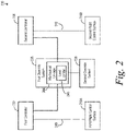
- the flight control system 230 includes a plurality of flight control surfaces 216A-216B, a first controller 232, a second controller 234, a first override system, 236, and a second override system 238.
- the flight control surfaces 216A-216B include a first flight control surface 216A and a second flight control surface 216B.
- the flight control surfaces 216A-216B can include, for example, one or more elevators, rudders, ailerons, flaps, spoilers, leading edge flaps, leading edge slats, and/or trim tabs.
- the first flight control surface 216A is coupled to the first controller 232 by a first control path 240
- the second flight control surface 216B is coupled to the second controller 234 by a second control path 242.
- the first control path 240 and the second control path 242 can provide respective mechanical and/or fly-by-wire connections between the first controller 232 and the first flight control surface 216A, and the second controller 234 and the second flight control surfaces 216B.
- the flight control system 230 can provide a reversible and/or an irreversible connection between the first controller 232 and the first flight control surface 216A, and the second controller 234 and the second flight control surface 216B.
- the first controller 232 can control the first flight control surface 216A and the second controller 234 can control the second flight control surface 216B.
- the first controller 232 can include a first control column, a first control stick, a first wheel, and/or a first rudder pedal, which is operable by a first pilot in a cockpit of the aerial vehicle 100 for controlling the first flight control surface 216A.
- the second controller 234 can include a second control column, a second control stick, a second wheel, and/or a second rudder pedal, which is operable by a second pilot in the cockpit for controlling the second flight control surface 216B.
- the first override system 236 includes a mechanical linkage 244 between the first controller 232 and the second controller 234.
- the first override system 236 is a resetting override system.
- the mechanical linkage 244 can include a load limiter 246 such as, for instance, a pogo or a bungee.
- the load limiter 246 can provide a mechanism for (i) coupling the first controller 232 and the second controller 234 when a force less than a first threshold amount of force is applied to the mechanical linkage 244 by the first controller 232 and the second controller 234, and (ii) temporarily decoupling the first controller 232 and the second controller 232 when a force greater than the first threshold amount of force is applied to the mechanical linkage 244 by the first controller 232 and the second controller 234.
- temporary decoupled it is meant that the mechanical linkage 244 restores the coupling between the first controller 232 and the second controller 234 when the force applied to the mechanical linkage 244 reduces to below the first threshold amount of force (as long as the mechanical linkage 244 has not been permanently disconnected by the second override system 238, as described below).
- the first override system 236 is configured such that: (i) while less than the first threshold amount of force is applied to the mechanical linkage 244 by the first controller 232 and the second controller 234, movement of the first controller 232 causes a corresponding movement of the second controller 234 and movement of the second controller 234 causes a corresponding movement of the first controller 232, and (ii) while greater than the first threshold amount of force is applied to the mechanical linkage 244 by the first controller 232 and the second controller 234, the first controller 232 and the second controller 234 move separately relative to each other.
- the first override system 236 allows the second controller 234 to be used to actuate the second flight control surface 216B.
- the first override system 236 allows the first controller 232 to be used to actuate the first flight control surface 216A. Accordingly, although the jam may impair operation of one of the first flight control surface 216A or the second flight control surface 216B, the aerial vehicle 100 can still be safely controlled using the other of the first flight control surface 216A or the second flight control surface 216B.
- the first threshold amount of force can be a value between approximately 160 N (35 pounds) and approximately 220 N (50 pounds) in one example, and between approximately 180 N (40 pounds) and approximately 200 N (45 pounds) in another example. Also as examples, in an implementation in which the first controller 232 and the second controller 234 are columns, the first threshold amount of force can be a value between approximately 240 N (55 pounds) and approximately 330 N (75 pounds) in one example, and between approximately 270 N (60 pounds) and approximately 310 N (70 pounds) in another example.
- the first threshold amount of force can be an amount that is unlikely to actuate the first override system 236 under certain flight conditions such as, for example, when the aerial vehicle 100 is in a stall. This can beneficially reduce (or prevent) inadvertent decoupling of the first controller 232 and the second controller 234.
- approximately with reference to amounts or measurement values, it is meant that the recited characteristic, parameter, or value need not be achieved exactly. Rather, deviations or variations, including, for example, tolerances, measurement error, measurement accuracy limitations, and other factors known to those skilled in the art, may occur in amounts that do not preclude the effect that the characteristic was intended to provide.
- the second override system 238 is operable to permanently and physically disconnect the mechanical linkage 244 between the first controller 232 and the second controller 234 responsive to greater than a second threshold amount of force applied to the mechanical linkage 244 by the first controller 232 and the second controller 234.
- the first controller 232 and the second controller 234 can move separately relative to each other responsive to any force (e.g., a force that is less than the first threshold amount of force applied to the mechanical linkage 244 by the first controller 232 and the second controller 234).
- the second override system 238 can be a device, which is external to mechanical linkage 244.
- the second override system 238 can include a bolt cutter, a wire cutter, and/or a cable cutter, which can be actuated to physically break or sever the mechanical linkage 244 between the first controller 232 and the second controller 234.
- the mechanical linkage 244 can include the second override system 238.
- the second override system 238 can include a shear pin, a solenoid actuated coupling, and/or a frangible nut along the mechanical linkage 244 between the first controller 232 and the second controller 234.
- the second threshold amount of force is greater than the first threshold amount of force.
- the second threshold amount of force can be a value greater than or equal to approximately 330 N (75 pounds) (e.g., for an implementation in which the first controller 232 and the second controller 234 are wheels).
- the second threshold amount of force can be greater than or equal to approximately 530 N (120 pounds) (e.g., for an implementation in which the first controller 232 and the second controller 234 are columns).
- the second threshold amount of force can be an amount of force that is a value between approximately 30% and approximately 100% greater than the first threshold amount of force.
- the second threshold amount of force can be an amount of force that reduces (or prevents) inadvertently disconnecting the mechanical linkage 244 between the first controller 232 and the second controller 234. This is beneficial because once the second override system 238 disconnects the mechanical linkage 244, the coupling between the first controller 232 and the second controller 234 cannot be restored during the flight. Rather, the mechanical linkage 244 can be restored after the flight by repair and/or replacement of the mechanical linkage 244.
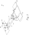
- the first controller 232 is coupled to the first flight control surface 216A by the first control path 240, and the second controller 234 is coupled to the second flight control surface 216B.
- the first controller 232 is a first wheel extending from a cockpit floor 348
- the second controller 234 is a second wheel extending from the cockpit floor 348.
- the first controller 232 and the second controller 234 can additionally or alternatively include respective control sticks and/or a rudder pedals in other examples.
- first flight control surface 216A is a first elevator and the second flight control surface 216B is a second elevator.
- first flight control surface 216A and the second flight control surface 216B can additionally or alternatively include one or more rudders, ailerons, flaps, spoilers, leading edge flaps, leading edge slats, and/or trim tabs.
- the first override system 236 includes the mechanical linkage 244 between the first controller 232 and the second controller 234.
- the second override system 238 is a shear pin along the mechanical linkage 244 at the first override system 236.
- the first pilot and/or the second pilot can fly the aerial vehicle 100 under normal operating conditions while the first controller 232 and the second controller 234 are not jammed.
- either pilot can apply an input force to the first controller 232 or the second controller 234, which causes the first controller 232 and the second controller 234 to apply to the mechanical linkage 244 a first force that is less than the first threshold amount of force.
- the input force causes the first controller 232 to move together with the second controller 234 and simultaneously actuates the first flight control surface 216A and the second flight control surface 216B.
- the first pilot and/or the second pilot can detect the jam by sensing an increased resistance to movement of the first controller 232 and/or the second controller 234.
- the jam can be along at least one of (i) the first control path 240 between the first controller 232 and the first control surface 216A, or (ii) the second control path 242 between the second controller 234 and the second control surface 216B. In either case, the input force for moving the first controller 232 and the second controller 234 is increased due to the mechanical linkage 244 between the first controller 232 and the second controller 234.
- the first pilot or the second pilot can apply an input force to the non-jammed controller, which causes the first controller 232 and the second controller 234 to apply to the mechanical linkage 244 a second force that is greater than the first threshold amount of force.
- This causes the first override system 236 to temporarily decouple the first controller 232 and the second controller 234.
- the second force causes the first controller 232 and the second controller 234 to move separately relative to each other, actuating one of the first flight control surface 216A or the second flight control surface 216B (i.e., the flight control surface 216A, 216B that is coupled to the non-jammed controller 232, 234).
- the first pilot and/or the second pilot can decide to actuate the second override system 238.
- the first pilot or the second pilot can apply an input force to the non-jammed one of the first controller 232 or the second controller 234, which causes the first controller 232 and the second controller 234 to apply to the mechanical linkage 244 a third force that is greater than a second threshold amount of force. This causes the second override system 238 to disconnect the mechanical linkage 244 between the first controller 232 and the second controller 234.
- the first pilot or the second pilot can move the first controller 232 separately from the second controller 234 with a reduced input force. Specifically, the first pilot or the second pilot can move the first controller 232 separately from the second controller 234 to actuate one of the first flight control surface 216A or the second flight control surface 216B even though the first controller 232 and the second controller 234 apply less than the first threshold amount of force to the mechanical linkage 244.
- Figure 4A and Figure 4B depict perspective views of a portion of a flight control system 230 before and after, respectively, the second override system 238 is actuated to disconnect the mechanical linkage 244.
- the first controller 232 is coupled to the second controller 234.
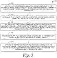
- the aerial vehicle includes a first controller configured to control a first flight control surface, a second controller configured to control a second flight control surface, a first override system including a mechanical linkage between the first controller and the second controller, and a second override system.
- the process 500 includes applying, by the first controller and the second controller to the mechanical linkage, a first force that is less than a first threshold amount of force to cause the first controller to move together with the second controller.
- the process 500 includes actuating the first flight control surface and the second flight control surface at block 512.
- the process 500 includes applying, by the first controller and the second controller to the mechanical linkage, a second force that is greater than the first threshold amount of force to cause the first controller and the second controller to move separately relative to each other.
- the process 500 includes actuating one of the first flight control surface or the second flight control surface at block 516.
- the process 500 includes applying, by the first controller and the second controller to the mechanical linkage, a third force that is greater than a second threshold amount of force to permanently and physically disconnect the mechanical linkage between the first controller and the second controller.
- the second threshold amount of force is greater than the first threshold amount of force.
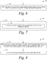
- Figures 6-15 depict additional aspects of the process 500 according to further examples.
- the process 500 can also include after applying the third force to permanently and physically disconnect the mechanical linkage at block 518, moving the first controller separately from the second controller at block 520.
- moving the first controller separately from the second controller at block 520 can include applying less than the first threshold amount of force to the mechanical linkage at block 522.
- the process 500 can also include, at block 524, detecting a jam along at least one of (i) a first control path between the first controller and the first control surface, or (ii) a second control path between the second controller and the second control surface. Also, as shown in Figure 8 , applying the second force at block 514 can be responsive to detecting the jam at block 524.
- applying the third force to permanently and physically disconnect the mechanical linkage at block 518 can include actuating a shear pin to disconnect the mechanical linkage at block 526.
- applying the third force to permanently and physically disconnect the mechanical linkage at block 518 can include, at block 528, actuating at least one of a group consisting of: a bolt cutter, a wire cutter, a cable cutter, a solenoid actuated coupling, and a frangible nut.
- applying the first force at block 510 can include moving the first controller to cause a corresponding movement of the second controller at block 530.
- moving the first controller at block 530 can include moving a first wheel in a cockpit of the aerial vehicle to cause a corresponding movement of a second wheel in the cockpit at block 532.
- moving the first controller at block 530 can include moving a first rudder pedal in a cockpit of the aerial vehicle to cause a corresponding movement of a second rudder pedal in the cockpit at block 534.
- actuating the first flight control surface and the second flight control surface at block 512 can include actuating a first aileron of the aerial vehicle and a second aileron of the aerial vehicle at block 536.
- actuating the first flight control surface and the second flight control surface at block 512 can include actuating a first elevator of the aerial vehicle and a second elevator of the aerial vehicle at block 538.
- One or more of the blocks shown in Figures 6-15 represents a module, a segment, or a portion of program code, which includes one or more instructions executable by a processor for implementing specific logical functions or steps in the process.
- the program code may be stored on any type of computer readable medium or data storage, for example, such as a storage device including a disk or hard drive. Further, the program code can be encoded on a computer-readable storage media in a machine-readable format, or on other non-transitory media or articles of manufacture.
- the computer readable medium includes non-transitory computer readable medium or memory, for example, such as computer-readable media that stores data for short periods of time like register memory, processor cache and Random Access Memory (RAM).
- the computer readable medium also includes non-transitory media, such as secondary or persistent long term storage, like read only memory (ROM), optical or magnetic disks, compact-disc read only memory (CD-ROM), for example.
- non-transitory media such as secondary or persistent long term storage, like read only memory (ROM), optical or magnetic disks, compact-disc read only memory (CD-ROM), for example.
- the computer readable media may also be any other volatile or nonvolatile storage systems.
- the computer readable medium may be considered a tangible computer readable storage medium, for example.
- components of the devices and/or systems described herein are configured to perform the functions such that the components are actually configured and structured (with hardware and/or software) to enable such performance.
- Example configurations then include one or more processors executing instructions to cause the system to perform the functions.
- components of the devices and/or systems are configured so as to be arranged or adapted to, capable of, or suited for performing the functions, such as when operated in a specific manner.
Landscapes
- Engineering & Computer Science (AREA)
- Aviation & Aerospace Engineering (AREA)
- Automation & Control Theory (AREA)
- Mechanical Engineering (AREA)
- Control Of Position, Course, Altitude, Or Attitude Of Moving Bodies (AREA)
- Transmission Devices (AREA)
- Toys (AREA)
Claims (14)
- System (230), das Folgendes umfasst:eine erste Steuerung (232), die so konfiguriert ist, dass sie eine erste Flugsteuerfläche (216A) eines Flugzeugs (100) steuert;eine zweite Steuerung (234), die so konfiguriert ist, dass sie eine zweite Flugsteuerfläche (216B) des Flugzeugs (100) steuert;ein erstes Übersteuerungssystem (236), das eine mechanische Verbindung (244) zwischen der ersten Steuerung (232) und der zweiten Steuerung (234) umfasst, wobei das erste Übersteuerungssystem (236) so konfiguriert ist, dass:(i) während eine Kraft, die kleiner als ein erster Kraftschwellenwert ist, durch die erste Steuerung (232) und die zweite Steuerung (234) auf die mechanische Verbindung (244) ausgeübt wird, eine Bewegung der ersten Steuerung (232) eine entsprechende Bewegung der zweiten Steuerung (234) bewirkt und eine Bewegung der zweiten Steuerung (234) eine entsprechende Bewegung der ersten Steuerung (232) bewirkt, und(ii) während eine Kraft, die größer als der erste Kraftschwellenwert ist, durch die erste Steuerung (232) und die zweite Steuerung (234) auf die mechanische Verbindung (244) ausgeübt wird, die erste Steuerung (234) und die zweite Steuerung (234) sich separat relativ zueinander bewegen; undein zweites Übersteuerungssystem (238), das betreibbar ist, um die mechanische Verbindung (244) zwischen der ersten Steuerung (232) und der zweiten Steuerung (234) dauerhaft und physikalisch zu trennen als Reaktion darauf, dass eine Kraft, die größer als ein zweiter Kraftschwellenwert ist, durch die erste Steuerung (232) und die zweite Steuerung (234) auf die mechanische Verbindung (244) ausgeübt wird, undwobei der zweite Kraftschwellenwert größer als der erste Kraftschwellenwert ist, undwobei, nachdem die mechanische Verbindung (244) durch das zweite Übersteuerungssystem (238) dauerhaft und physikalisch getrennt ist, die erste Steuerung (232) und die zweite Steuerung (234) so konfiguriert sind, dass sie sich separat relativ zueinander bewegen als Reaktion darauf, dass eine Kraft, die kleiner als der erste Kraftschwellenwert ist, durch die erste Steuerung (232) und die zweite Steuerung (234) auf die mechanische Verbindung (244) ausgeübt wird.
- System nach Anspruch 1, wobei das zweite Übersteuerungssystem (238) einen Scherstift umfasst, der so konfiguriert ist, dass er die mechanische Verbindung (244) dauerhaft und physikalsch trennt.
- System nach Anspruch 1 oder 2, wobei das zweite Übersteuerungssystem (238) mindestens eines aus einer Gruppe umfasst, die aus den Folgenden besteht: einem Bolzenschneider, einem Drahtschneider, einem Kabelschneider, einer Solenoid-betätigten Kupplung und einer zerbrechlichen Mutter.
- System nach einem der Ansprüche 1 bis 3, wobei das erste Übersteuerungssystem (236) einen Lastbegrenzer (246) umfasst.
- System nach einem der Ansprüche 1 bis 4, wobei die erste Steuerung (232) ein erstes Ruderpedal in einem Cockpit des Flugzeugs (100) umfasst und die zweite Steuerung (234) ein zweites Ruderpedal in dem Cockpit des Flugzeugs (100) umfasst.
- System nach einem der Ansprüche 1 bis 5, wobei die erste Steuerung (232) ein erstes Steuerhorn in einem Cockpit des Flugzeugs (100) umfasst und die zweite Steuerung (234) ein zweites Steuerhorn in dem Cockpit des Flugzeugs (100) umfasst.
- System nach einem der Ansprüche 1 bis 6, wobei die erste Flugsteuerfläche (216A) ein erstes Querruder (120) des Flugzeugs (100) umfasst und die zweite Flugsteuerfläche (216B) ein zweites Querruder (120) des Flugzeugs (100) umfasst.
- System nach einem der Ansprüche 1 bis 7, wobei die erste Flugsteuerfläche (216A) ein erstes Höhenruder (122) des Flugzeugs (100) umfasst und die zweite Flugsteuerfläche (216B) ein zweites Höhenruder (122) des Flugzeugs (100) umfasst.
- Verfahren zum Betreiben eines Flugzeugs (100), wobei das Flugzeug (100) eine erste Steuerung (232), die zum Steuern einer ersten Flugsteuerfläche (216A) konfiguriert ist, eine zweite Steuerung (234), die zum Steuern einer zweiten Flugsteuerfläche (216B) konfiguriert ist, ein erstes Übersteuerungssystem (236), das eine mechanische Verbindung (244) zwischen der ersten Steuerung (232) und der zweiten Steuerung (234) enthält, und ein zweites Übersteuerungssystem (238) umfasst, wbei das Verfahren Folgendes umfasst:Ausüben einer ersten Kraft, die kleiner als ein erster Kraftschwellenwert ist, durch die erste Steuerung (232) und die zweite Steuerung (234) auf die mechanische Verbindung (244), um zu bewirken, dass das erste Übersteuerungssystem (236) bewirkt, dass die erste Steuerung (232) sich zusammen mit der zweiten Steuerung (234) bewegt;als Reaktion auf das Ausüben der ersten Kraft, Betätigen der ersten Flugsteuerfläche (216A) und der zweiten Flugsteuerfläche (216B);Ausüben einer zweiten Kraft, die größer als der erste Kraftschwellenwert ist, durch die erste Steuerung (232) und die zweite Steuerung (234) auf die mechanische Verbindung (244), um zu bewirken, dass das erste Übersteuerungssystem (236) bewirkt, dass die erste Steuerung (232) und die zweite Steuerung (234) sich separat relativ zueinander zu bewegen;als Reaktion auf das Ausüben der zweiten Kraft, Betätigen der ersten Flugsteuerfläche (216A) oder der zweiten Flugsteuerfläche (216B);Ausüben einer dritten Kraft, die größer als ein zweiter Kraftschwellenwert ist, durch die erste Steuerung (232) und die zweite Steuerung (234) auf die mechanische Verbindung (244), um zu bewirken, dass das zweite Übersteuerungssystem (238) bewirkt, dass die mechanische Verbindung (244) zwischen der ersten Steuerung (232) und der zweiten Steuerung (234) dauerhaft und physikalisch getrennt wird; undAusüben einer vierten Kraft, die kleiner als der erste Kraftschwellenwert ist, durch die erste Steuerung (232) und die zweite Steuerung (234) auf die mechanische Verbindung (244), um zu bewirken, dass die erste Steuerung (232) und die zweite Steuerung (234) sich separat relativ zueinander bewegen;wobei der zweite Kraftschwellenwert größer als der erste Kraftschwellenwert ist.
- Verfahren nach Anspruch 9, ferner umfassend das Erkennen einer Störung entlang mindestens einem von (i) einem ersten Steuerweg (240) zwischen der ersten Steuerung (232) und der ersten Steuerfläche oder (ii) einem zweiten Steuerweg (242) zwischen der zweiten Steuerung (234) und der zweiten Steuerfläche,
wobei das Ausüben der zweiten Kraft als Reaktion auf das Erkennen der Störung erfolgt. - Verfahren nach Anspruch 9 oder 10, wobei das Ausüben der dritten Kraft, um zu bewirken, dass das zweite Übersteuerungssystem (238) die mechanische Verbindung (244) dauerhaft und physikalisch trennt, das Betätigen eines Scherstifts umfasst, um die mechanische Verbindung (244) zu trennen.
- Verfahren nach einem der Ansprüche 9 bis 11, wobei das Ausüben der dritten Kraft, um zu bewirken, dass das zweite Übersteuerungssystem (238) die mechanische Verbindung (244) dauerhaft und physikalsch trennt, das Betätigen mindestens eines aus einer Gruppe umfasst, die aus den Folgenden besteht: einem Bolzenschneider, einem Drahtschneider, einem Kabelschneider, einer Solenoid-betätigten Kupplung und einer zerbrechlichen Mutter.
- Verfahren nach einem der Ansprüche 9 bis 12, wobei das Bewegen der ersten Steuerung (232) das Bewegen eines ersten Ruderpedals in einem Cockpit des Flugzeugs (100) umfasst, um eine entsprechende Bewegung eines zweiten Ruderpedals in dem Cockpit zu bewirken.
- Verfahren nach einem der Ansprüche 9 bis 13, wobei das Betätigen der ersten Flugsteuerfläche (216A) und der zweiten Flugsteuerfläche (216B) Folgendes umfasst:Betätigen eines ersten Querruders (120) des Flugzeugs (100) und eines zweiten Querruders (120) des Flugzeugs (100); und/oderBetätigen eines ersten Höhenruders (122) des Flugzeugs (100) und eines zweiten Höhenruders (122) des Flugzeugs (100).
Applications Claiming Priority (1)
| Application Number | Priority Date | Filing Date | Title |
|---|---|---|---|
| US15/888,957 US10793257B2 (en) | 2018-02-05 | 2018-02-05 | Flight control systems and methods for an aerial vehicle |
Publications (2)
| Publication Number | Publication Date |
|---|---|
| EP3521157A1 EP3521157A1 (de) | 2019-08-07 |
| EP3521157B1 true EP3521157B1 (de) | 2022-09-28 |
Family
ID=65279468
Family Applications (1)
| Application Number | Title | Priority Date | Filing Date |
|---|---|---|---|
| EP19155328.8A Active EP3521157B1 (de) | 2018-02-05 | 2019-02-04 | Flugsteuerungssystem und verfahren für ein luftfahrzeug |
Country Status (7)
| Country | Link |
|---|---|
| US (1) | US10793257B2 (de) |
| EP (1) | EP3521157B1 (de) |
| JP (1) | JP7231393B2 (de) |
| CN (1) | CN110116799A (de) |
| BR (1) | BR102019002105A2 (de) |
| CA (1) | CA3031120C (de) |
| RU (1) | RU2018143548A (de) |
Families Citing this family (2)
| Publication number | Priority date | Publication date | Assignee | Title |
|---|---|---|---|---|
| CN111976955B (zh) * | 2020-07-24 | 2023-03-14 | 中国航空工业集团公司西安飞行自动控制研究所 | 民机电传飞控双驾驶杆盘的单侧卡阻故障处理方法和装置 |
| US20220194561A1 (en) * | 2020-12-17 | 2022-06-23 | The Boeing Company | Systems and Methods for Overriding Autonomous Control of a Device |
Citations (1)
| Publication number | Priority date | Publication date | Assignee | Title |
|---|---|---|---|---|
| US20140077025A1 (en) * | 2012-02-10 | 2014-03-20 | Bell Helicopter Textron Inc. | Pilot Control System with Adjustable Pedals |
Family Cites Families (10)
| Publication number | Priority date | Publication date | Assignee | Title |
|---|---|---|---|---|
| US2478173A (en) * | 1943-06-03 | 1949-08-09 | William E Austin | Safety device for aircraft controls |
| US3902379A (en) * | 1973-12-03 | 1975-09-02 | Us Navy | High load, quick-disconnect link |
| US3949958A (en) * | 1973-12-07 | 1976-04-13 | Lockheed Aircraft Corporation | Pitch control system |
| US4403756A (en) | 1980-12-22 | 1983-09-13 | The Boeing Company | Bifurcated feel simulator for aircraft |
| US5782436A (en) * | 1996-01-19 | 1998-07-21 | Mcdonnell Douglas Corporation | Torque tube breakout mechanism |
| US20030183728A1 (en) | 2002-03-29 | 2003-10-02 | The Boeing Company | Aircraft control surface controller and associated method |
| JP4691121B2 (ja) | 2008-02-20 | 2011-06-01 | 三菱重工業株式会社 | 操縦システム、操縦桿リンク切り離し方法 |
| EP2695810B1 (de) * | 2012-08-09 | 2016-10-19 | Airbus Operations GmbH | Antriebssystem zur Steuerung von Oberflächen eines Flugzeugs |
| US9437056B2 (en) | 2014-10-09 | 2016-09-06 | The Boeing Company | Methods and apparatus for operating flight control systems of aircrafts |
| US10913527B2 (en) * | 2016-03-22 | 2021-02-09 | The Boeing Company | Method and apparatus for latent fault detection and management for fly-by-wire flight control systems |
-
2018
- 2018-02-05 US US15/888,957 patent/US10793257B2/en active Active
- 2018-12-10 RU RU2018143548A patent/RU2018143548A/ru unknown
- 2018-12-13 JP JP2018233403A patent/JP7231393B2/ja active Active
-
2019
- 2019-01-07 CN CN201910011022.0A patent/CN110116799A/zh active Pending
- 2019-01-23 CA CA3031120A patent/CA3031120C/en active Active
- 2019-02-01 BR BR102019002105-5A patent/BR102019002105A2/pt active Search and Examination
- 2019-02-04 EP EP19155328.8A patent/EP3521157B1/de active Active
Patent Citations (1)
| Publication number | Priority date | Publication date | Assignee | Title |
|---|---|---|---|---|
| US20140077025A1 (en) * | 2012-02-10 | 2014-03-20 | Bell Helicopter Textron Inc. | Pilot Control System with Adjustable Pedals |
Also Published As
| Publication number | Publication date |
|---|---|
| CA3031120C (en) | 2023-06-20 |
| CN110116799A (zh) | 2019-08-13 |
| RU2018143548A (ru) | 2020-06-10 |
| JP7231393B2 (ja) | 2023-03-01 |
| EP3521157A1 (de) | 2019-08-07 |
| BR102019002105A2 (pt) | 2019-09-17 |
| RU2018143548A3 (de) | 2022-04-14 |
| US10793257B2 (en) | 2020-10-06 |
| CA3031120A1 (en) | 2019-08-05 |
| US20190241253A1 (en) | 2019-08-08 |
| JP2019135141A (ja) | 2019-08-15 |
Similar Documents
| Publication | Publication Date | Title |
|---|---|---|
| US8935015B2 (en) | Flight control system with alternate control path | |
| AU2018214162B2 (en) | System and method for optimizing horizontal tail loads | |
| US6446911B1 (en) | Method for controlling actuators on a vehicle | |
| US8033509B2 (en) | Load optimized redundant flight control surface actuation system and method | |
| EP1873057B1 (de) | Aktiver Ruderpedalmechanismus mit Fremdobjektschlagtoleranz und Gelenkbremse | |
| US8401716B2 (en) | Flight control systems | |
| US7701161B2 (en) | Motor balanced active user interface assembly | |
| US8380364B2 (en) | Manual and computerized flight control system with natural feedback | |
| EP2052966B1 (de) | Geschwindigkeitsbeschränktes aktives Pilotsteuerorgansystem und Verfahren | |
| US7984880B2 (en) | Mechanisms and methods for providing rudder control assist during symmetrical and asymmetrical thrust conditions | |
| EP3521157B1 (de) | Flugsteuerungssystem und verfahren für ein luftfahrzeug | |
| JPS60161299A (ja) | 航空機の操縦装置 | |
| JP3012644B1 (ja) | サ―ボアクチュエ―タ装置および航空機操縦制御装置 | |
| EP2078997A2 (de) | Mensch-Maschine-Schnittstelle mit variabler Null-Losbrechkraft | |
| EP2072394A2 (de) | Fluidverbindung von Flugzeugsteuerungsbenutzeroberflächen |
Legal Events
| Date | Code | Title | Description |
|---|---|---|---|
| PUAI | Public reference made under article 153(3) epc to a published international application that has entered the european phase |
Free format text: ORIGINAL CODE: 0009012 |
|
| STAA | Information on the status of an ep patent application or granted ep patent |
Free format text: STATUS: REQUEST FOR EXAMINATION WAS MADE |
|
| 17P | Request for examination filed |
Effective date: 20190204 |
|
| AK | Designated contracting states |
Kind code of ref document: A1 Designated state(s): AL AT BE BG CH CY CZ DE DK EE ES FI FR GB GR HR HU IE IS IT LI LT LU LV MC MK MT NL NO PL PT RO RS SE SI SK SM TR |
|
| AX | Request for extension of the european patent |
Extension state: BA ME |
|
| STAA | Information on the status of an ep patent application or granted ep patent |
Free format text: STATUS: EXAMINATION IS IN PROGRESS |
|
| STAA | Information on the status of an ep patent application or granted ep patent |
Free format text: STATUS: EXAMINATION IS IN PROGRESS |
|
| 17Q | First examination report despatched |
Effective date: 20210120 |
|
| RIC1 | Information provided on ipc code assigned before grant |
Ipc: B64C 13/42 20060101ALN20220302BHEP Ipc: B64C 13/50 20060101ALN20220302BHEP Ipc: B64C 13/28 20060101ALI20220302BHEP Ipc: B64C 13/12 20060101AFI20220302BHEP |
|
| GRAP | Despatch of communication of intention to grant a patent |
Free format text: ORIGINAL CODE: EPIDOSNIGR1 |
|
| STAA | Information on the status of an ep patent application or granted ep patent |
Free format text: STATUS: GRANT OF PATENT IS INTENDED |
|
| RIC1 | Information provided on ipc code assigned before grant |
Ipc: B64C 13/42 20060101ALN20220317BHEP Ipc: B64C 13/50 20060101ALN20220317BHEP Ipc: B64C 13/28 20060101ALI20220317BHEP Ipc: B64C 13/12 20060101AFI20220317BHEP |
|
| INTG | Intention to grant announced |
Effective date: 20220413 |
|
| GRAS | Grant fee paid |
Free format text: ORIGINAL CODE: EPIDOSNIGR3 |
|
| GRAA | (expected) grant |
Free format text: ORIGINAL CODE: 0009210 |
|
| STAA | Information on the status of an ep patent application or granted ep patent |
Free format text: STATUS: THE PATENT HAS BEEN GRANTED |
|
| AK | Designated contracting states |
Kind code of ref document: B1 Designated state(s): AL AT BE BG CH CY CZ DE DK EE ES FI FR GB GR HR HU IE IS IT LI LT LU LV MC MK MT NL NO PL PT RO RS SE SI SK SM TR |
|
| REG | Reference to a national code |
Ref country code: GB Ref legal event code: FG4D |
|
| REG | Reference to a national code |
Ref country code: CH Ref legal event code: EP |
|
| REG | Reference to a national code |
Ref country code: DE Ref legal event code: R096 Ref document number: 602019019923 Country of ref document: DE |
|
| REG | Reference to a national code |
Ref country code: AT Ref legal event code: REF Ref document number: 1521098 Country of ref document: AT Kind code of ref document: T Effective date: 20221015 |
|
| REG | Reference to a national code |
Ref country code: IE Ref legal event code: FG4D |
|
| REG | Reference to a national code |
Ref country code: LT Ref legal event code: MG9D |
|
| PG25 | Lapsed in a contracting state [announced via postgrant information from national office to epo] |
Ref country code: SE Free format text: LAPSE BECAUSE OF FAILURE TO SUBMIT A TRANSLATION OF THE DESCRIPTION OR TO PAY THE FEE WITHIN THE PRESCRIBED TIME-LIMIT Effective date: 20220928 Ref country code: RS Free format text: LAPSE BECAUSE OF FAILURE TO SUBMIT A TRANSLATION OF THE DESCRIPTION OR TO PAY THE FEE WITHIN THE PRESCRIBED TIME-LIMIT Effective date: 20220928 Ref country code: NO Free format text: LAPSE BECAUSE OF FAILURE TO SUBMIT A TRANSLATION OF THE DESCRIPTION OR TO PAY THE FEE WITHIN THE PRESCRIBED TIME-LIMIT Effective date: 20221228 Ref country code: LV Free format text: LAPSE BECAUSE OF FAILURE TO SUBMIT A TRANSLATION OF THE DESCRIPTION OR TO PAY THE FEE WITHIN THE PRESCRIBED TIME-LIMIT Effective date: 20220928 Ref country code: LT Free format text: LAPSE BECAUSE OF FAILURE TO SUBMIT A TRANSLATION OF THE DESCRIPTION OR TO PAY THE FEE WITHIN THE PRESCRIBED TIME-LIMIT Effective date: 20220928 Ref country code: FI Free format text: LAPSE BECAUSE OF FAILURE TO SUBMIT A TRANSLATION OF THE DESCRIPTION OR TO PAY THE FEE WITHIN THE PRESCRIBED TIME-LIMIT Effective date: 20220928 |
|
| REG | Reference to a national code |
Ref country code: NL Ref legal event code: MP Effective date: 20220928 |
|
| REG | Reference to a national code |
Ref country code: AT Ref legal event code: MK05 Ref document number: 1521098 Country of ref document: AT Kind code of ref document: T Effective date: 20220928 |
|
| PG25 | Lapsed in a contracting state [announced via postgrant information from national office to epo] |
Ref country code: HR Free format text: LAPSE BECAUSE OF FAILURE TO SUBMIT A TRANSLATION OF THE DESCRIPTION OR TO PAY THE FEE WITHIN THE PRESCRIBED TIME-LIMIT Effective date: 20220928 Ref country code: GR Free format text: LAPSE BECAUSE OF FAILURE TO SUBMIT A TRANSLATION OF THE DESCRIPTION OR TO PAY THE FEE WITHIN THE PRESCRIBED TIME-LIMIT Effective date: 20221229 |
|
| RAP4 | Party data changed (patent owner data changed or rights of a patent transferred) |
Owner name: THE BOEING COMPANY |
|
| PG25 | Lapsed in a contracting state [announced via postgrant information from national office to epo] |
Ref country code: SM Free format text: LAPSE BECAUSE OF FAILURE TO SUBMIT A TRANSLATION OF THE DESCRIPTION OR TO PAY THE FEE WITHIN THE PRESCRIBED TIME-LIMIT Effective date: 20220928 Ref country code: RO Free format text: LAPSE BECAUSE OF FAILURE TO SUBMIT A TRANSLATION OF THE DESCRIPTION OR TO PAY THE FEE WITHIN THE PRESCRIBED TIME-LIMIT Effective date: 20220928 Ref country code: PT Free format text: LAPSE BECAUSE OF FAILURE TO SUBMIT A TRANSLATION OF THE DESCRIPTION OR TO PAY THE FEE WITHIN THE PRESCRIBED TIME-LIMIT Effective date: 20230130 Ref country code: ES Free format text: LAPSE BECAUSE OF FAILURE TO SUBMIT A TRANSLATION OF THE DESCRIPTION OR TO PAY THE FEE WITHIN THE PRESCRIBED TIME-LIMIT Effective date: 20220928 Ref country code: CZ Free format text: LAPSE BECAUSE OF FAILURE TO SUBMIT A TRANSLATION OF THE DESCRIPTION OR TO PAY THE FEE WITHIN THE PRESCRIBED TIME-LIMIT Effective date: 20220928 Ref country code: AT Free format text: LAPSE BECAUSE OF FAILURE TO SUBMIT A TRANSLATION OF THE DESCRIPTION OR TO PAY THE FEE WITHIN THE PRESCRIBED TIME-LIMIT Effective date: 20220928 |
|
| PGFP | Annual fee paid to national office [announced via postgrant information from national office to epo] |
Ref country code: FR Payment date: 20230223 Year of fee payment: 5 |
|
| PG25 | Lapsed in a contracting state [announced via postgrant information from national office to epo] |
Ref country code: SK Free format text: LAPSE BECAUSE OF FAILURE TO SUBMIT A TRANSLATION OF THE DESCRIPTION OR TO PAY THE FEE WITHIN THE PRESCRIBED TIME-LIMIT Effective date: 20220928 Ref country code: PL Free format text: LAPSE BECAUSE OF FAILURE TO SUBMIT A TRANSLATION OF THE DESCRIPTION OR TO PAY THE FEE WITHIN THE PRESCRIBED TIME-LIMIT Effective date: 20220928 Ref country code: IS Free format text: LAPSE BECAUSE OF FAILURE TO SUBMIT A TRANSLATION OF THE DESCRIPTION OR TO PAY THE FEE WITHIN THE PRESCRIBED TIME-LIMIT Effective date: 20230128 Ref country code: EE Free format text: LAPSE BECAUSE OF FAILURE TO SUBMIT A TRANSLATION OF THE DESCRIPTION OR TO PAY THE FEE WITHIN THE PRESCRIBED TIME-LIMIT Effective date: 20220928 |
|
| P01 | Opt-out of the competence of the unified patent court (upc) registered |
Effective date: 20230516 |
|
| REG | Reference to a national code |
Ref country code: DE Ref legal event code: R097 Ref document number: 602019019923 Country of ref document: DE |
|
| PG25 | Lapsed in a contracting state [announced via postgrant information from national office to epo] |
Ref country code: NL Free format text: LAPSE BECAUSE OF FAILURE TO SUBMIT A TRANSLATION OF THE DESCRIPTION OR TO PAY THE FEE WITHIN THE PRESCRIBED TIME-LIMIT Effective date: 20220928 Ref country code: AL Free format text: LAPSE BECAUSE OF FAILURE TO SUBMIT A TRANSLATION OF THE DESCRIPTION OR TO PAY THE FEE WITHIN THE PRESCRIBED TIME-LIMIT Effective date: 20220928 |
|
| PG25 | Lapsed in a contracting state [announced via postgrant information from national office to epo] |
Ref country code: DK Free format text: LAPSE BECAUSE OF FAILURE TO SUBMIT A TRANSLATION OF THE DESCRIPTION OR TO PAY THE FEE WITHIN THE PRESCRIBED TIME-LIMIT Effective date: 20220928 |
|
| PLBE | No opposition filed within time limit |
Free format text: ORIGINAL CODE: 0009261 |
|
| STAA | Information on the status of an ep patent application or granted ep patent |
Free format text: STATUS: NO OPPOSITION FILED WITHIN TIME LIMIT |
|
| 26N | No opposition filed |
Effective date: 20230629 |
|
| PG25 | Lapsed in a contracting state [announced via postgrant information from national office to epo] |
Ref country code: MC Free format text: LAPSE BECAUSE OF FAILURE TO SUBMIT A TRANSLATION OF THE DESCRIPTION OR TO PAY THE FEE WITHIN THE PRESCRIBED TIME-LIMIT Effective date: 20220928 |
|
| REG | Reference to a national code |
Ref country code: CH Ref legal event code: PL |
|
| REG | Reference to a national code |
Ref country code: BE Ref legal event code: MM Effective date: 20230228 |
|
| PG25 | Lapsed in a contracting state [announced via postgrant information from national office to epo] |
Ref country code: LU Free format text: LAPSE BECAUSE OF NON-PAYMENT OF DUE FEES Effective date: 20230204 Ref country code: LI Free format text: LAPSE BECAUSE OF NON-PAYMENT OF DUE FEES Effective date: 20230228 Ref country code: CH Free format text: LAPSE BECAUSE OF NON-PAYMENT OF DUE FEES Effective date: 20230228 |
|
| PG25 | Lapsed in a contracting state [announced via postgrant information from national office to epo] |
Ref country code: SI Free format text: LAPSE BECAUSE OF FAILURE TO SUBMIT A TRANSLATION OF THE DESCRIPTION OR TO PAY THE FEE WITHIN THE PRESCRIBED TIME-LIMIT Effective date: 20220928 |
|
| REG | Reference to a national code |
Ref country code: IE Ref legal event code: MM4A |
|
| PG25 | Lapsed in a contracting state [announced via postgrant information from national office to epo] |
Ref country code: IE Free format text: LAPSE BECAUSE OF NON-PAYMENT OF DUE FEES Effective date: 20230204 |
|
| PG25 | Lapsed in a contracting state [announced via postgrant information from national office to epo] |
Ref country code: BE Free format text: LAPSE BECAUSE OF NON-PAYMENT OF DUE FEES Effective date: 20230228 |
|
| PGFP | Annual fee paid to national office [announced via postgrant information from national office to epo] |
Ref country code: DE Payment date: 20240228 Year of fee payment: 6 Ref country code: GB Payment date: 20240227 Year of fee payment: 6 |