EP3521115A1 - Dispositif de frein électrique - Google Patents
Dispositif de frein électrique Download PDFInfo
- Publication number
- EP3521115A1 EP3521115A1 EP17856038.9A EP17856038A EP3521115A1 EP 3521115 A1 EP3521115 A1 EP 3521115A1 EP 17856038 A EP17856038 A EP 17856038A EP 3521115 A1 EP3521115 A1 EP 3521115A1
- Authority
- EP
- European Patent Office
- Prior art keywords
- load
- pressing force
- estimator
- correlation
- switching
- Prior art date
- Legal status (The legal status is an assumption and is not a legal conclusion. Google has not performed a legal analysis and makes no representation as to the accuracy of the status listed.)
- Granted
Links
- 238000003825 pressing Methods 0.000 claims abstract description 77
- 230000007423 decrease Effects 0.000 claims abstract description 52
- 230000008859 change Effects 0.000 claims description 12
- 230000007246 mechanism Effects 0.000 description 11
- 238000004364 calculation method Methods 0.000 description 6
- 230000001419 dependent effect Effects 0.000 description 5
- 238000006243 chemical reaction Methods 0.000 description 4
- 230000003247 decreasing effect Effects 0.000 description 3
- 238000001514 detection method Methods 0.000 description 3
- 238000006073 displacement reaction Methods 0.000 description 3
- 230000006872 improvement Effects 0.000 description 3
- 230000003044 adaptive effect Effects 0.000 description 2
- 238000007792 addition Methods 0.000 description 2
- 239000003638 chemical reducing agent Substances 0.000 description 2
- 238000012217 deletion Methods 0.000 description 2
- 230000037430 deletion Effects 0.000 description 2
- 238000004519 manufacturing process Methods 0.000 description 2
- 238000000034 method Methods 0.000 description 2
- 230000008569 process Effects 0.000 description 2
- 230000009467 reduction Effects 0.000 description 2
- 238000013459 approach Methods 0.000 description 1
- 238000010276 construction Methods 0.000 description 1
- 238000009795 derivation Methods 0.000 description 1
- 238000013461 design Methods 0.000 description 1
- 238000010586 diagram Methods 0.000 description 1
- 230000000694 effects Effects 0.000 description 1
- 230000007613 environmental effect Effects 0.000 description 1
- 230000002349 favourable effect Effects 0.000 description 1
- 230000006698 induction Effects 0.000 description 1
- 230000003287 optical effect Effects 0.000 description 1
- 230000002441 reversible effect Effects 0.000 description 1
- 230000000153 supplemental effect Effects 0.000 description 1
- 230000001360 synchronised effect Effects 0.000 description 1
- 230000009466 transformation Effects 0.000 description 1
- 238000013519 translation Methods 0.000 description 1
Images


Classifications
-
- B—PERFORMING OPERATIONS; TRANSPORTING
- B60—VEHICLES IN GENERAL
- B60T—VEHICLE BRAKE CONTROL SYSTEMS OR PARTS THEREOF; BRAKE CONTROL SYSTEMS OR PARTS THEREOF, IN GENERAL; ARRANGEMENT OF BRAKING ELEMENTS ON VEHICLES IN GENERAL; PORTABLE DEVICES FOR PREVENTING UNWANTED MOVEMENT OF VEHICLES; VEHICLE MODIFICATIONS TO FACILITATE COOLING OF BRAKES
- B60T8/00—Arrangements for adjusting wheel-braking force to meet varying vehicular or ground-surface conditions, e.g. limiting or varying distribution of braking force
- B60T8/17—Using electrical or electronic regulation means to control braking
-
- B—PERFORMING OPERATIONS; TRANSPORTING
- B60—VEHICLES IN GENERAL
- B60T—VEHICLE BRAKE CONTROL SYSTEMS OR PARTS THEREOF; BRAKE CONTROL SYSTEMS OR PARTS THEREOF, IN GENERAL; ARRANGEMENT OF BRAKING ELEMENTS ON VEHICLES IN GENERAL; PORTABLE DEVICES FOR PREVENTING UNWANTED MOVEMENT OF VEHICLES; VEHICLE MODIFICATIONS TO FACILITATE COOLING OF BRAKES
- B60T8/00—Arrangements for adjusting wheel-braking force to meet varying vehicular or ground-surface conditions, e.g. limiting or varying distribution of braking force
- B60T8/32—Arrangements for adjusting wheel-braking force to meet varying vehicular or ground-surface conditions, e.g. limiting or varying distribution of braking force responsive to a speed condition, e.g. acceleration or deceleration
- B60T8/321—Arrangements for adjusting wheel-braking force to meet varying vehicular or ground-surface conditions, e.g. limiting or varying distribution of braking force responsive to a speed condition, e.g. acceleration or deceleration deceleration
- B60T8/3255—Systems in which the braking action is dependent on brake pedal data
-
- B—PERFORMING OPERATIONS; TRANSPORTING
- B60—VEHICLES IN GENERAL
- B60T—VEHICLE BRAKE CONTROL SYSTEMS OR PARTS THEREOF; BRAKE CONTROL SYSTEMS OR PARTS THEREOF, IN GENERAL; ARRANGEMENT OF BRAKING ELEMENTS ON VEHICLES IN GENERAL; PORTABLE DEVICES FOR PREVENTING UNWANTED MOVEMENT OF VEHICLES; VEHICLE MODIFICATIONS TO FACILITATE COOLING OF BRAKES
- B60T1/00—Arrangements of braking elements, i.e. of those parts where braking effect occurs specially for vehicles
- B60T1/02—Arrangements of braking elements, i.e. of those parts where braking effect occurs specially for vehicles acting by retarding wheels
- B60T1/06—Arrangements of braking elements, i.e. of those parts where braking effect occurs specially for vehicles acting by retarding wheels acting otherwise than on tread, e.g. employing rim, drum, disc, or transmission or on double wheels
- B60T1/065—Arrangements of braking elements, i.e. of those parts where braking effect occurs specially for vehicles acting by retarding wheels acting otherwise than on tread, e.g. employing rim, drum, disc, or transmission or on double wheels employing disc
-
- B—PERFORMING OPERATIONS; TRANSPORTING
- B60—VEHICLES IN GENERAL
- B60T—VEHICLE BRAKE CONTROL SYSTEMS OR PARTS THEREOF; BRAKE CONTROL SYSTEMS OR PARTS THEREOF, IN GENERAL; ARRANGEMENT OF BRAKING ELEMENTS ON VEHICLES IN GENERAL; PORTABLE DEVICES FOR PREVENTING UNWANTED MOVEMENT OF VEHICLES; VEHICLE MODIFICATIONS TO FACILITATE COOLING OF BRAKES
- B60T13/00—Transmitting braking action from initiating means to ultimate brake actuator with power assistance or drive; Brake systems incorporating such transmitting means, e.g. air-pressure brake systems
- B60T13/74—Transmitting braking action from initiating means to ultimate brake actuator with power assistance or drive; Brake systems incorporating such transmitting means, e.g. air-pressure brake systems with electrical assistance or drive
- B60T13/746—Transmitting braking action from initiating means to ultimate brake actuator with power assistance or drive; Brake systems incorporating such transmitting means, e.g. air-pressure brake systems with electrical assistance or drive and mechanical transmission of the braking action
-
- B—PERFORMING OPERATIONS; TRANSPORTING
- B60—VEHICLES IN GENERAL
- B60T—VEHICLE BRAKE CONTROL SYSTEMS OR PARTS THEREOF; BRAKE CONTROL SYSTEMS OR PARTS THEREOF, IN GENERAL; ARRANGEMENT OF BRAKING ELEMENTS ON VEHICLES IN GENERAL; PORTABLE DEVICES FOR PREVENTING UNWANTED MOVEMENT OF VEHICLES; VEHICLE MODIFICATIONS TO FACILITATE COOLING OF BRAKES
- B60T17/00—Component parts, details, or accessories of power brake systems not covered by groups B60T8/00, B60T13/00 or B60T15/00, or presenting other characteristic features
- B60T17/18—Safety devices; Monitoring
- B60T17/22—Devices for monitoring or checking brake systems; Signal devices
- B60T17/221—Procedure or apparatus for checking or keeping in a correct functioning condition of brake systems
-
- B—PERFORMING OPERATIONS; TRANSPORTING
- B60—VEHICLES IN GENERAL
- B60T—VEHICLE BRAKE CONTROL SYSTEMS OR PARTS THEREOF; BRAKE CONTROL SYSTEMS OR PARTS THEREOF, IN GENERAL; ARRANGEMENT OF BRAKING ELEMENTS ON VEHICLES IN GENERAL; PORTABLE DEVICES FOR PREVENTING UNWANTED MOVEMENT OF VEHICLES; VEHICLE MODIFICATIONS TO FACILITATE COOLING OF BRAKES
- B60T8/00—Arrangements for adjusting wheel-braking force to meet varying vehicular or ground-surface conditions, e.g. limiting or varying distribution of braking force
- B60T8/17—Using electrical or electronic regulation means to control braking
- B60T8/171—Detecting parameters used in the regulation; Measuring values used in the regulation
-
- B—PERFORMING OPERATIONS; TRANSPORTING
- B60—VEHICLES IN GENERAL
- B60T—VEHICLE BRAKE CONTROL SYSTEMS OR PARTS THEREOF; BRAKE CONTROL SYSTEMS OR PARTS THEREOF, IN GENERAL; ARRANGEMENT OF BRAKING ELEMENTS ON VEHICLES IN GENERAL; PORTABLE DEVICES FOR PREVENTING UNWANTED MOVEMENT OF VEHICLES; VEHICLE MODIFICATIONS TO FACILITATE COOLING OF BRAKES
- B60T8/00—Arrangements for adjusting wheel-braking force to meet varying vehicular or ground-surface conditions, e.g. limiting or varying distribution of braking force
- B60T8/17—Using electrical or electronic regulation means to control braking
- B60T8/172—Determining control parameters used in the regulation, e.g. by calculations involving measured or detected parameters
-
- B—PERFORMING OPERATIONS; TRANSPORTING
- B60—VEHICLES IN GENERAL
- B60T—VEHICLE BRAKE CONTROL SYSTEMS OR PARTS THEREOF; BRAKE CONTROL SYSTEMS OR PARTS THEREOF, IN GENERAL; ARRANGEMENT OF BRAKING ELEMENTS ON VEHICLES IN GENERAL; PORTABLE DEVICES FOR PREVENTING UNWANTED MOVEMENT OF VEHICLES; VEHICLE MODIFICATIONS TO FACILITATE COOLING OF BRAKES
- B60T8/00—Arrangements for adjusting wheel-braking force to meet varying vehicular or ground-surface conditions, e.g. limiting or varying distribution of braking force
- B60T8/32—Arrangements for adjusting wheel-braking force to meet varying vehicular or ground-surface conditions, e.g. limiting or varying distribution of braking force responsive to a speed condition, e.g. acceleration or deceleration
- B60T8/52—Torque sensing, i.e. wherein the braking action is controlled by forces producing or tending to produce a twisting or rotating motion on a braked rotating member
-
- F—MECHANICAL ENGINEERING; LIGHTING; HEATING; WEAPONS; BLASTING
- F16—ENGINEERING ELEMENTS AND UNITS; GENERAL MEASURES FOR PRODUCING AND MAINTAINING EFFECTIVE FUNCTIONING OF MACHINES OR INSTALLATIONS; THERMAL INSULATION IN GENERAL
- F16D—COUPLINGS FOR TRANSMITTING ROTATION; CLUTCHES; BRAKES
- F16D55/00—Brakes with substantially-radial braking surfaces pressed together in axial direction, e.g. disc brakes
- F16D55/02—Brakes with substantially-radial braking surfaces pressed together in axial direction, e.g. disc brakes with axially-movable discs or pads pressed against axially-located rotating members
-
- F—MECHANICAL ENGINEERING; LIGHTING; HEATING; WEAPONS; BLASTING
- F16—ENGINEERING ELEMENTS AND UNITS; GENERAL MEASURES FOR PRODUCING AND MAINTAINING EFFECTIVE FUNCTIONING OF MACHINES OR INSTALLATIONS; THERMAL INSULATION IN GENERAL
- F16D—COUPLINGS FOR TRANSMITTING ROTATION; CLUTCHES; BRAKES
- F16D65/00—Parts or details
- F16D65/14—Actuating mechanisms for brakes; Means for initiating operation at a predetermined position
- F16D65/16—Actuating mechanisms for brakes; Means for initiating operation at a predetermined position arranged in or on the brake
- F16D65/18—Actuating mechanisms for brakes; Means for initiating operation at a predetermined position arranged in or on the brake adapted for drawing members together, e.g. for disc brakes
-
- H—ELECTRICITY
- H02—GENERATION; CONVERSION OR DISTRIBUTION OF ELECTRIC POWER
- H02P—CONTROL OR REGULATION OF ELECTRIC MOTORS, ELECTRIC GENERATORS OR DYNAMO-ELECTRIC CONVERTERS; CONTROLLING TRANSFORMERS, REACTORS OR CHOKE COILS
- H02P23/00—Arrangements or methods for the control of AC motors characterised by a control method other than vector control
- H02P23/14—Estimation or adaptation of motor parameters, e.g. rotor time constant, flux, speed, current or voltage
-
- H—ELECTRICITY
- H02—GENERATION; CONVERSION OR DISTRIBUTION OF ELECTRIC POWER
- H02P—CONTROL OR REGULATION OF ELECTRIC MOTORS, ELECTRIC GENERATORS OR DYNAMO-ELECTRIC CONVERTERS; CONTROLLING TRANSFORMERS, REACTORS OR CHOKE COILS
- H02P3/00—Arrangements for stopping or slowing electric motors, generators, or dynamo-electric converters
- H02P3/06—Arrangements for stopping or slowing electric motors, generators, or dynamo-electric converters for stopping or slowing an individual dynamo-electric motor or dynamo-electric converter
- H02P3/18—Arrangements for stopping or slowing electric motors, generators, or dynamo-electric converters for stopping or slowing an individual dynamo-electric motor or dynamo-electric converter for stopping or slowing an ac motor
-
- B—PERFORMING OPERATIONS; TRANSPORTING
- B60—VEHICLES IN GENERAL
- B60T—VEHICLE BRAKE CONTROL SYSTEMS OR PARTS THEREOF; BRAKE CONTROL SYSTEMS OR PARTS THEREOF, IN GENERAL; ARRANGEMENT OF BRAKING ELEMENTS ON VEHICLES IN GENERAL; PORTABLE DEVICES FOR PREVENTING UNWANTED MOVEMENT OF VEHICLES; VEHICLE MODIFICATIONS TO FACILITATE COOLING OF BRAKES
- B60T2270/00—Further aspects of brake control systems not otherwise provided for
- B60T2270/40—Failsafe aspects of brake control systems
- B60T2270/413—Plausibility monitoring, cross check, redundancy
-
- F—MECHANICAL ENGINEERING; LIGHTING; HEATING; WEAPONS; BLASTING
- F16—ENGINEERING ELEMENTS AND UNITS; GENERAL MEASURES FOR PRODUCING AND MAINTAINING EFFECTIVE FUNCTIONING OF MACHINES OR INSTALLATIONS; THERMAL INSULATION IN GENERAL
- F16D—COUPLINGS FOR TRANSMITTING ROTATION; CLUTCHES; BRAKES
- F16D2121/00—Type of actuator operation force
- F16D2121/18—Electric or magnetic
- F16D2121/24—Electric or magnetic using motors
-
- F—MECHANICAL ENGINEERING; LIGHTING; HEATING; WEAPONS; BLASTING
- F16—ENGINEERING ELEMENTS AND UNITS; GENERAL MEASURES FOR PRODUCING AND MAINTAINING EFFECTIVE FUNCTIONING OF MACHINES OR INSTALLATIONS; THERMAL INSULATION IN GENERAL
- F16D—COUPLINGS FOR TRANSMITTING ROTATION; CLUTCHES; BRAKES
- F16D2125/00—Components of actuators
- F16D2125/18—Mechanical mechanisms
- F16D2125/44—Mechanical mechanisms transmitting rotation
- F16D2125/46—Rotating members in mutual engagement
- F16D2125/48—Rotating members in mutual engagement with parallel stationary axes, e.g. spur gears
Definitions
- Patent Document 1 an electric brake actuator that uses an electric motor, a linear motion mechanism, and a speed reducer or reduction gear
- Patent Document 2 an electric actuator that uses a planetary roller mechanism and an electric motor
- Patent Document 3 An electric brake that detects pressing force by use of a strain gauge has also been proposed (Patent Document 3).
- an object of the present invention is to provide an electric brake device in which: hysteresis in a load sensor is appropriately compensated for, whereby the control accuracy of braking is improved; hysteresis is allowed in the load sensor whereby designing is facilitated; and thus, low costs and space-saving designing are enabled.
- the electric brake device may include an angle estimator configured to estimate an angle of the electric motor 3, wherein the indirect load estimator 18 may estimate the pressing force on the basis of a correlation between the pressing force and the angle of the electric motor 3 estimated by the angle estimator.
- the correlation between the brake load and the motor angle is generated dependent on the rigidity of the electric brake device, and thus, feedback control based on the motor angle is enabled.
- the electric brake device may include an angle estimator configured to estimate an angle of the electric motor 3, wherein on the basis of a change amount of the angle of the electric motor, the control switching unit 19b may perform determination as to a drive amount of the electric brake actuator 1 at a time of performing switching from the indirect load estimator 18 to the direct load estimator 17. It is difficult to perform determination as to switching between a pressure increase operation and a pressure decrease operation, on the basis of the load sensor 6. However, the determination can be performed on the basis of the drive amount of the electric brake actuator 1.
- Fig. 1 shows a configuration example of an electric brake device including an electric brake actuator (hereinafter, simply referred to as electric actuator) 1 and an electric brake control device 2.
- This configuration example mainly shows components that are necessary for this embodiment, and components such as a power supply device and other sensors (e.g., a thermistor) that are necessary for an actual system configuration are provided as appropriate, irrespective of the expression of this drawing.
- This electric brake device is used in, for example, braking of a wheel of an automobile (not shown), or braking of a rotational drive unit in an industrial machine, a machine tool, or a transporting machine.
- the electric actuator 1 includes a brake rotor 7 and a friction member 8.
- the electric actuator 1 generates a braking force by causing the friction member 8 to be in contact with the brake rotor 7 while being pressed thereto via the friction member operator 4 due to rotation of the electric motor 3.
- the brake rotor 7 may be a brake disc or a brake drum.
- the friction member 8 is implemented as a brake pad or the like.
- the friction member operator 4 includes: the linear motion mechanism 4a described later which converts transmitted rotary motion into linear motion so as to cause the friction member 8 to advance/retract; and a speed reducer or reduction gear 4b which reduces the speed of rotary motion of the electric motor 3 to transmit the reduced speed rotation to the linear motion mechanism 4a.
- the electric motor 3 is configured as a permanent magnet synchronous motor, for example, and in that case, such a configuration saves space and realizes high torque, and thus, is preferable.
- the electric motor 3 may be a DC motor using a brush, a reluctance motor not using a permanent magnet, an induction motor, or the like.
- the linear motion mechanism 4a is implemented by various types of screw mechanisms such as a planetary roller screw or a ball screw, a ball ramp, or the like, and it is possible to use various types of mechanisms that convert rotary motion into linear motion through operation or the like along the inclined-shaped structure in the circumferential direction of the rotational shaft included in such mechanisms.
- the angle estimator 5 shown in Fig. 1 if a resolver, a magnetic encoder, or the like is used, high accuracy and high reliability are realized and thus, such a configuration is preferable.
- various types of sensors such as an optical encoder can also be used.
- the angle estimator 5 may perform, without using an angle sensor, sensorless angle estimation in which the motor angle is estimated on the basis of the relationship or the like between voltage and current.
- the load sensor 6 it is possible to use a magnetic sensor, a strain sensor, a pressure sensor, or the like that detects displacement, for example.
- the motor driver 15 applies a motor current to the electric motor 3 in accordance with the output from the motor current controller 14.
- the motor driver 15 converts a direct current of a battery into an alternating current power by a half-bridge circuit using a switching element such as a FET.
- the motor driver 15 is configured to perform PWM control in which, when the converted alternating current is to be applied to the electric motor 3, the voltage applied to the motor is determined on the basis of a predetermined duty ratio with respect to the voltage applied to the switching element.
- the motor driver 15 may be configured to perform PAM control, instead of the PWM control, with a transformation circuit or the like (not shown) provided.
- the electric brake control device 2 having the basic configuration as described above includes a direct load estimator 17, an indirect load estimator 18, and a hysteresis interpolator 19 described below.
- the direct load estimator 17 estimates the pressing force, using the output of the load sensor 6.
- the indirect load estimator 18 estimates the pressing force without using the output of the load sensor 6, and performs load estimation on the basis of a correlation or the like between the output of the load sensor and the state quantity of a component other than the load sensor obtained in advance.
- the direct load estimator 17 includes a first-estimation-correlation-using estimation unit 17a and a second-estimation-correlation-using estimation unit 17b.
- the first-estimation-correlation-using estimation unit 17a estimates the pressing force during pressure increase on the basis of a correlation between the output change of the load sensor 6 and the pressure increase amount of the pressing force, i.e., a first estimation correlation which is a correlation between the output of the load sensor 6 and the actual brake load when the brake load is increased.
- the second-estimation-correlation-using estimation unit 17b estimates the pressing force during pressure decrease on the basis of a correlation between the output change of the load sensor 6 and the pressure decrease amount of the pressing force, i.e., a second estimation correlation which is a correlation between the output of the load sensor 6 and the actual brake load when the brake load is decreased.
- the first and second estimation correlations are set in the respective estimation units 17a, 17b, as a sensor output-load pressure increase conversion table, and a sensor output-load pressure decrease conversion table, for example. Instead of using the tables, direct calculation by a predetermined function may be performed.
- the indirect load estimator 18 estimates the pressing force without using the output of the load sensor 6 as described above.
- the indirect load estimator 18 may perform the estimation on the basis of a correlation between the brake load and the motor angle dependent on the rigidity or the like of the electric brake actuator 1, may perform the estimation on the basis of a correlation between the brake load and the motor current dependent on the efficiency of the electric brake actuator, the motor characteristics, or the like, or may use these approaches in combination as appropriate.
- the load is estimated by use of a motor angle estimated by an angle estimator 5.
- the load is estimated by use of a motor current detected by the current estimator 16.
- a conversion table may be used, or direct calculation by a predetermined function may be used, as in the case described above.
- the pressure increase/decrease switching determination unit 19a detects a state where the motion of the linear motion mechanism 4a has been changed from a pressure increasing motion to a pressure decreasing motion, and conversely, a state where the motion of the linear motion mechanism 4a has been changed from a pressure decreasing motion to a pressure increasing motion. More specifically, for example, by use of an angle estimation value from the angle estimator 5, the pressure increase/decrease switching determination unit 19a determines, as the state where the pressure increase and the pressure decrease have been switched, between a state where the changing direction of the motor angle of the electric motor 3 has been changed from the pressure-increasing direction to the pressure-decreasing direction and a reverse state thereof.
- the control switching unit 19b has a function of appropriately switching a load estimation function in accordance with the determination or the like by the pressure increase/decrease switching determination unit 19a. Specifically, for example, in a state where control is being performed by use of the first estimation correlation (load sensor correlation during pressure increase) in the direct load estimator 17 during pressure increase of the brake load of the electric brake actuator 1, if switching from pressure increase to pressure decrease occurs, hysteresis occurs in the output of the load sensor 6. Therefore, the control switching unit 19b switches the control to the brake load control that uses the indirect load estimator 18 which does not use the output of the load sensor 6. That is, a switch 20 is switched such that the load estimation value to be inputted to the brake load controller 13 is inputted from the indirect load estimator 18. This switching of the switch 20 is performed by the control switching unit 19b.
- the switch 20 can be considered as a conceptual description and can be also implemented, not as a physical switch, but as a branching process in a data flow in a computing unit.
- the control switching unit 19b switches the switch 20 such that the output of the direct load estimator 17 is inputted to the brake load controller 13, and the brake load controller 13 performs brake load control by use of the load sensor correlation during pressure decrease.
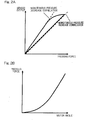
- Fig. 2A shows a correlation between the pressing force (brake load) and the output of the load sensor 6.
- This correlation includes: relatively linear load sensor output correlations (monotonous pressure increase correlation, monotonous pressure decrease correlation) during monotonous pressure increase and monotonous pressure decrease; and nonlinear hysteresis between the monotonous pressure increase correlation and the monotonous pressure decrease correlation.
- Fig. 2B shows a correlation between the motor angle of the electric motor 3 and the pressing force (brake load).
- the pressing force increases in accordance with increase in the motor angle, but the increase rate of the pressing force also increases in accordance with increase in the motor angle, and thus, a nonlinear relationship curve is obtained.
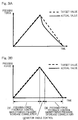
- Fig. 3A and Fig. 3B each show an operation example of the electric brake device in a case where the indirect load estimator 18, in Fig. 1 , based on the correlation between the pressing force (brake load) and the motor angle of the electric motor 3 is used.
- the broken line indicates the target value of the pressing force (brake load)
- the solid line indicates the actual value of the pressing force (brake load).
- Fig. 3A shows an example in which the pressing force (brake load) is controlled by use of only the estimation value from the direct load estimator 17 shown in Fig. 1 .
- the actual value of the pressing force (brake load) deviates greatly from the target value, and the control accuracy for the pressing force (brake load) is reduced.
- Fig. 3B shows a case where the present embodiment is applied to Fig. 3A .
- pressing force feedback control which uses the estimation value from the direct load estimator 17 is performed.
- section (2) In a state until the drive amount of the electric brake actuator 1 reaches a predetermined amount (section (2)) after the pressure increase operation and the pressure decrease operation has been switched (in the present embodiment, after switching has been performed by the control switching unit 19b in line with the determination result by the pressure increase/decrease switching determination unit 19a), motor angle control, i.e., follow-up control based on the indirect load estimator 18, is performed.
- the present embodiment since the influence due to the hysteresis in the load sensor 6 is appropriately compensated for, the control accuracy of the electric brake is improved. In addition, since the hysteresis in the load sensor 6 is allowed in this manner, designing is facilitated, and low costs and space-saving designing are enabled. Therefore, if the present embodiment is applied to braking of automobile wheels, improvement in the safety and improvement in the driving feeling can be attained.
Landscapes
- Engineering & Computer Science (AREA)
- Mechanical Engineering (AREA)
- Transportation (AREA)
- General Engineering & Computer Science (AREA)
- Power Engineering (AREA)
- Braking Systems And Boosters (AREA)
- Regulating Braking Force (AREA)
- Braking Arrangements (AREA)
Applications Claiming Priority (2)
| Application Number | Priority Date | Filing Date | Title |
|---|---|---|---|
| JP2016189174A JP6752668B2 (ja) | 2016-09-28 | 2016-09-28 | 電動ブレーキ装置 |
| PCT/JP2017/034490 WO2018062086A1 (fr) | 2016-09-28 | 2017-09-25 | Dispositif de frein électrique |
Publications (3)
| Publication Number | Publication Date |
|---|---|
| EP3521115A1 true EP3521115A1 (fr) | 2019-08-07 |
| EP3521115A4 EP3521115A4 (fr) | 2020-04-15 |
| EP3521115B1 EP3521115B1 (fr) | 2022-08-03 |
Family
ID=61759664
Family Applications (1)
| Application Number | Title | Priority Date | Filing Date |
|---|---|---|---|
| EP17856038.9A Active EP3521115B1 (fr) | 2016-09-28 | 2017-09-25 | Dispositif de frein électrique |
Country Status (5)
| Country | Link |
|---|---|
| US (1) | US10759399B2 (fr) |
| EP (1) | EP3521115B1 (fr) |
| JP (1) | JP6752668B2 (fr) |
| CN (1) | CN109789858B (fr) |
| WO (1) | WO2018062086A1 (fr) |
Families Citing this family (6)
| Publication number | Priority date | Publication date | Assignee | Title |
|---|---|---|---|---|
| DE102019206612B3 (de) * | 2019-05-08 | 2020-07-16 | Volkswagen Aktiengesellschaft | Verfahren zur Steuerung eines elektromechanischen Bremssystems sowie elektromechanisches Bremssystem |
| FR3116497B1 (fr) * | 2020-11-23 | 2024-02-16 | Foundation Brakes France | Procédé de commande du couple de serrage d’un frein électromécanique amélioré |
| KR102548683B1 (ko) * | 2021-04-02 | 2023-06-27 | 현대모비스 주식회사 | 전동식 부스터 제동 장치 및 그 제어방법 |
| KR20230040594A (ko) * | 2021-09-16 | 2023-03-23 | 현대모비스 주식회사 | 전동식 부스터 및 그 제어방법 |
| JP2024034797A (ja) * | 2022-09-01 | 2024-03-13 | 株式会社デンソー | 車両用制動装置 |
| JP2024106631A (ja) * | 2023-01-27 | 2024-08-08 | 株式会社アドヴィックス | 電動制動装置 |
Family Cites Families (14)
| Publication number | Priority date | Publication date | Assignee | Title |
|---|---|---|---|---|
| JP3166401B2 (ja) | 1993-05-17 | 2001-05-14 | 日産自動車株式会社 | 電動ブレーキ用アクチュエータ |
| DE19652230A1 (de) | 1996-12-16 | 1998-06-18 | Teves Gmbh Alfred | Elektromechanisch betätigbare Scheibenbremse |
| JP4715062B2 (ja) * | 2000-12-01 | 2011-07-06 | 株式会社デンソー | 車両用ブレーキ装置 |
| JP4898123B2 (ja) | 2005-01-13 | 2012-03-14 | Ntn株式会社 | 電動式直動アクチュエータおよび電動式ブレーキ装置 |
| JP2008049800A (ja) * | 2006-08-24 | 2008-03-06 | Hitachi Ltd | 電動ブレーキ装置およびその制御方法 |
| JP5676382B2 (ja) * | 2011-07-13 | 2015-02-25 | Ntn株式会社 | 電動ブレーキ装置 |
| JP5845889B2 (ja) * | 2011-12-27 | 2016-01-20 | 株式会社アドヴィックス | 車両の制動制御装置 |
| CN105050871B (zh) * | 2013-03-15 | 2017-09-12 | 株式会社爱德克斯 | 车辆的电动制动装置 |
| JP6080682B2 (ja) * | 2013-05-17 | 2017-02-15 | Ntn株式会社 | 電動式直動アクチュエータおよび電動ブレーキ装置 |
| KR101500303B1 (ko) * | 2013-07-25 | 2015-03-18 | 주식회사 만도 | 전자식 브레이크 장치 및 그 제어 방법 |
| JP6306426B2 (ja) * | 2014-05-14 | 2018-04-04 | Ntn株式会社 | 電動ブレーキ装置 |
| JP6300635B2 (ja) * | 2014-05-21 | 2018-03-28 | Ntn株式会社 | 電動ブレーキ装置 |
| JP6313152B2 (ja) * | 2014-07-18 | 2018-04-18 | Ntn株式会社 | 電動ブレーキ装置 |
| JP6584877B2 (ja) * | 2014-09-25 | 2019-10-02 | Ntn株式会社 | 電動ブレーキシステム |
-
2016
- 2016-09-28 JP JP2016189174A patent/JP6752668B2/ja active Active
-
2017
- 2017-09-25 WO PCT/JP2017/034490 patent/WO2018062086A1/fr unknown
- 2017-09-25 EP EP17856038.9A patent/EP3521115B1/fr active Active
- 2017-09-25 CN CN201780059617.2A patent/CN109789858B/zh active Active
-
2019
- 2019-03-26 US US16/364,867 patent/US10759399B2/en active Active
Also Published As
| Publication number | Publication date |
|---|---|
| EP3521115B1 (fr) | 2022-08-03 |
| US10759399B2 (en) | 2020-09-01 |
| CN109789858B (zh) | 2021-06-29 |
| US20190217830A1 (en) | 2019-07-18 |
| JP6752668B2 (ja) | 2020-09-09 |
| WO2018062086A1 (fr) | 2018-04-05 |
| CN109789858A (zh) | 2019-05-21 |
| JP2018052251A (ja) | 2018-04-05 |
| EP3521115A4 (fr) | 2020-04-15 |
Similar Documents
| Publication | Publication Date | Title |
|---|---|---|
| US10759399B2 (en) | Electric brake device | |
| US10384659B2 (en) | Electric brake device | |
| WO2017043461A1 (fr) | Dispositif de frein motorisé | |
| CN109890673B (zh) | 电动制动装置 | |
| EP3339121B1 (fr) | Dispositif de frein électrique | |
| US11441626B2 (en) | Electric linear actuator and electric brake device | |
| WO2016181898A1 (fr) | Dispositif de moteur électrique et actionneur de mouvement linéaire électrique | |
| WO2019151146A1 (fr) | Actionneur électrique et dispositif de freinage électrique | |
| US11001246B2 (en) | Electric brake device | |
| WO2018052068A1 (fr) | Appareil de frein électrique | |
| WO2019159813A1 (fr) | Dispositif de type frein électrique et système de frein électrique | |
| JP7250191B2 (ja) | 電動式直動アクチュエータおよび電動ブレーキ装置 | |
| WO2019049971A1 (fr) | Actionneur électrique et dispositif de moteur électrique | |
| JP6986903B2 (ja) | 電動式直動アクチュエータおよび電動ブレーキ装置 | |
| JP2020043665A (ja) | 電動式アクチュエータおよび電動ブレーキ装置 | |
| JP2019018693A (ja) | 電動式直動アクチュエータおよび電動ブレーキ装置 | |
| JP6906398B2 (ja) | 電動ブレーキ装置 |
Legal Events
| Date | Code | Title | Description |
|---|---|---|---|
| STAA | Information on the status of an ep patent application or granted ep patent |
Free format text: STATUS: THE INTERNATIONAL PUBLICATION HAS BEEN MADE |
|
| PUAI | Public reference made under article 153(3) epc to a published international application that has entered the european phase |
Free format text: ORIGINAL CODE: 0009012 |
|
| STAA | Information on the status of an ep patent application or granted ep patent |
Free format text: STATUS: REQUEST FOR EXAMINATION WAS MADE |
|
| 17P | Request for examination filed |
Effective date: 20190415 |
|
| AK | Designated contracting states |
Kind code of ref document: A1 Designated state(s): AL AT BE BG CH CY CZ DE DK EE ES FI FR GB GR HR HU IE IS IT LI LT LU LV MC MK MT NL NO PL PT RO RS SE SI SK SM TR |
|
| AX | Request for extension of the european patent |
Extension state: BA ME |
|
| DAV | Request for validation of the european patent (deleted) | ||
| DAX | Request for extension of the european patent (deleted) | ||
| A4 | Supplementary search report drawn up and despatched |
Effective date: 20200312 |
|
| RIC1 | Information provided on ipc code assigned before grant |
Ipc: B60T 13/74 20060101ALI20200306BHEP Ipc: B60T 8/52 20060101ALI20200306BHEP Ipc: B60T 8/171 20060101ALI20200306BHEP Ipc: B60T 8/32 20060101ALI20200306BHEP Ipc: B60T 8/17 20060101AFI20200306BHEP |
|
| GRAP | Despatch of communication of intention to grant a patent |
Free format text: ORIGINAL CODE: EPIDOSNIGR1 |
|
| STAA | Information on the status of an ep patent application or granted ep patent |
Free format text: STATUS: GRANT OF PATENT IS INTENDED |
|
| INTG | Intention to grant announced |
Effective date: 20220414 |
|
| GRAS | Grant fee paid |
Free format text: ORIGINAL CODE: EPIDOSNIGR3 |
|
| GRAA | (expected) grant |
Free format text: ORIGINAL CODE: 0009210 |
|
| STAA | Information on the status of an ep patent application or granted ep patent |
Free format text: STATUS: THE PATENT HAS BEEN GRANTED |
|
| AK | Designated contracting states |
Kind code of ref document: B1 Designated state(s): AL AT BE BG CH CY CZ DE DK EE ES FI FR GB GR HR HU IE IS IT LI LT LU LV MC MK MT NL NO PL PT RO RS SE SI SK SM TR |
|
| REG | Reference to a national code |
Ref country code: AT Ref legal event code: REF Ref document number: 1508511 Country of ref document: AT Kind code of ref document: T Effective date: 20220815 Ref country code: CH Ref legal event code: EP |
|
| REG | Reference to a national code |
Ref country code: DE Ref legal event code: R096 Ref document number: 602017060317 Country of ref document: DE |
|
| REG | Reference to a national code |
Ref country code: IE Ref legal event code: FG4D |
|
| PGFP | Annual fee paid to national office [announced via postgrant information from national office to epo] |
Ref country code: DE Payment date: 20220920 Year of fee payment: 6 |
|
| REG | Reference to a national code |
Ref country code: LT Ref legal event code: MG9D |
|
| PGFP | Annual fee paid to national office [announced via postgrant information from national office to epo] |
Ref country code: FR Payment date: 20220726 Year of fee payment: 6 |
|
| REG | Reference to a national code |
Ref country code: NL Ref legal event code: MP Effective date: 20220803 |
|
| PG25 | Lapsed in a contracting state [announced via postgrant information from national office to epo] |
Ref country code: SE Free format text: LAPSE BECAUSE OF FAILURE TO SUBMIT A TRANSLATION OF THE DESCRIPTION OR TO PAY THE FEE WITHIN THE PRESCRIBED TIME-LIMIT Effective date: 20220803 Ref country code: RS Free format text: LAPSE BECAUSE OF FAILURE TO SUBMIT A TRANSLATION OF THE DESCRIPTION OR TO PAY THE FEE WITHIN THE PRESCRIBED TIME-LIMIT Effective date: 20220803 Ref country code: PT Free format text: LAPSE BECAUSE OF FAILURE TO SUBMIT A TRANSLATION OF THE DESCRIPTION OR TO PAY THE FEE WITHIN THE PRESCRIBED TIME-LIMIT Effective date: 20221205 Ref country code: NO Free format text: LAPSE BECAUSE OF FAILURE TO SUBMIT A TRANSLATION OF THE DESCRIPTION OR TO PAY THE FEE WITHIN THE PRESCRIBED TIME-LIMIT Effective date: 20221103 Ref country code: NL Free format text: LAPSE BECAUSE OF FAILURE TO SUBMIT A TRANSLATION OF THE DESCRIPTION OR TO PAY THE FEE WITHIN THE PRESCRIBED TIME-LIMIT Effective date: 20220803 Ref country code: LV Free format text: LAPSE BECAUSE OF FAILURE TO SUBMIT A TRANSLATION OF THE DESCRIPTION OR TO PAY THE FEE WITHIN THE PRESCRIBED TIME-LIMIT Effective date: 20220803 Ref country code: LT Free format text: LAPSE BECAUSE OF FAILURE TO SUBMIT A TRANSLATION OF THE DESCRIPTION OR TO PAY THE FEE WITHIN THE PRESCRIBED TIME-LIMIT Effective date: 20220803 Ref country code: FI Free format text: LAPSE BECAUSE OF FAILURE TO SUBMIT A TRANSLATION OF THE DESCRIPTION OR TO PAY THE FEE WITHIN THE PRESCRIBED TIME-LIMIT Effective date: 20220803 Ref country code: ES Free format text: LAPSE BECAUSE OF FAILURE TO SUBMIT A TRANSLATION OF THE DESCRIPTION OR TO PAY THE FEE WITHIN THE PRESCRIBED TIME-LIMIT Effective date: 20220803 |
|
| REG | Reference to a national code |
Ref country code: AT Ref legal event code: MK05 Ref document number: 1508511 Country of ref document: AT Kind code of ref document: T Effective date: 20220803 |
|
| PG25 | Lapsed in a contracting state [announced via postgrant information from national office to epo] |
Ref country code: PL Free format text: LAPSE BECAUSE OF FAILURE TO SUBMIT A TRANSLATION OF THE DESCRIPTION OR TO PAY THE FEE WITHIN THE PRESCRIBED TIME-LIMIT Effective date: 20220803 Ref country code: IS Free format text: LAPSE BECAUSE OF FAILURE TO SUBMIT A TRANSLATION OF THE DESCRIPTION OR TO PAY THE FEE WITHIN THE PRESCRIBED TIME-LIMIT Effective date: 20221203 Ref country code: HR Free format text: LAPSE BECAUSE OF FAILURE TO SUBMIT A TRANSLATION OF THE DESCRIPTION OR TO PAY THE FEE WITHIN THE PRESCRIBED TIME-LIMIT Effective date: 20220803 Ref country code: GR Free format text: LAPSE BECAUSE OF FAILURE TO SUBMIT A TRANSLATION OF THE DESCRIPTION OR TO PAY THE FEE WITHIN THE PRESCRIBED TIME-LIMIT Effective date: 20221104 |
|
| PG25 | Lapsed in a contracting state [announced via postgrant information from national office to epo] |
Ref country code: SM Free format text: LAPSE BECAUSE OF FAILURE TO SUBMIT A TRANSLATION OF THE DESCRIPTION OR TO PAY THE FEE WITHIN THE PRESCRIBED TIME-LIMIT Effective date: 20220803 Ref country code: RO Free format text: LAPSE BECAUSE OF FAILURE TO SUBMIT A TRANSLATION OF THE DESCRIPTION OR TO PAY THE FEE WITHIN THE PRESCRIBED TIME-LIMIT Effective date: 20220803 Ref country code: DK Free format text: LAPSE BECAUSE OF FAILURE TO SUBMIT A TRANSLATION OF THE DESCRIPTION OR TO PAY THE FEE WITHIN THE PRESCRIBED TIME-LIMIT Effective date: 20220803 Ref country code: CZ Free format text: LAPSE BECAUSE OF FAILURE TO SUBMIT A TRANSLATION OF THE DESCRIPTION OR TO PAY THE FEE WITHIN THE PRESCRIBED TIME-LIMIT Effective date: 20220803 Ref country code: AT Free format text: LAPSE BECAUSE OF FAILURE TO SUBMIT A TRANSLATION OF THE DESCRIPTION OR TO PAY THE FEE WITHIN THE PRESCRIBED TIME-LIMIT Effective date: 20220803 |
|
| REG | Reference to a national code |
Ref country code: CH Ref legal event code: PL |
|
| REG | Reference to a national code |
Ref country code: DE Ref legal event code: R097 Ref document number: 602017060317 Country of ref document: DE |
|
| REG | Reference to a national code |
Ref country code: BE Ref legal event code: MM Effective date: 20220930 |
|
| PG25 | Lapsed in a contracting state [announced via postgrant information from national office to epo] |
Ref country code: SK Free format text: LAPSE BECAUSE OF FAILURE TO SUBMIT A TRANSLATION OF THE DESCRIPTION OR TO PAY THE FEE WITHIN THE PRESCRIBED TIME-LIMIT Effective date: 20220803 Ref country code: MC Free format text: LAPSE BECAUSE OF FAILURE TO SUBMIT A TRANSLATION OF THE DESCRIPTION OR TO PAY THE FEE WITHIN THE PRESCRIBED TIME-LIMIT Effective date: 20220803 Ref country code: EE Free format text: LAPSE BECAUSE OF FAILURE TO SUBMIT A TRANSLATION OF THE DESCRIPTION OR TO PAY THE FEE WITHIN THE PRESCRIBED TIME-LIMIT Effective date: 20220803 |
|
| PLBE | No opposition filed within time limit |
Free format text: ORIGINAL CODE: 0009261 |
|
| STAA | Information on the status of an ep patent application or granted ep patent |
Free format text: STATUS: NO OPPOSITION FILED WITHIN TIME LIMIT |
|
| PG25 | Lapsed in a contracting state [announced via postgrant information from national office to epo] |
Ref country code: LU Free format text: LAPSE BECAUSE OF NON-PAYMENT OF DUE FEES Effective date: 20220925 Ref country code: AL Free format text: LAPSE BECAUSE OF FAILURE TO SUBMIT A TRANSLATION OF THE DESCRIPTION OR TO PAY THE FEE WITHIN THE PRESCRIBED TIME-LIMIT Effective date: 20220803 |
|
| 26N | No opposition filed |
Effective date: 20230504 |
|
| GBPC | Gb: european patent ceased through non-payment of renewal fee |
Effective date: 20221103 |
|
| PG25 | Lapsed in a contracting state [announced via postgrant information from national office to epo] |
Ref country code: LI Free format text: LAPSE BECAUSE OF NON-PAYMENT OF DUE FEES Effective date: 20220930 Ref country code: IE Free format text: LAPSE BECAUSE OF NON-PAYMENT OF DUE FEES Effective date: 20220925 Ref country code: CH Free format text: LAPSE BECAUSE OF NON-PAYMENT OF DUE FEES Effective date: 20220930 |
|
| PG25 | Lapsed in a contracting state [announced via postgrant information from national office to epo] |
Ref country code: SI Free format text: LAPSE BECAUSE OF FAILURE TO SUBMIT A TRANSLATION OF THE DESCRIPTION OR TO PAY THE FEE WITHIN THE PRESCRIBED TIME-LIMIT Effective date: 20220803 |
|
| PG25 | Lapsed in a contracting state [announced via postgrant information from national office to epo] |
Ref country code: BE Free format text: LAPSE BECAUSE OF NON-PAYMENT OF DUE FEES Effective date: 20220930 |
|
| PG25 | Lapsed in a contracting state [announced via postgrant information from national office to epo] |
Ref country code: GB Free format text: LAPSE BECAUSE OF NON-PAYMENT OF DUE FEES Effective date: 20221103 |
|
| PG25 | Lapsed in a contracting state [announced via postgrant information from national office to epo] |
Ref country code: HU Free format text: LAPSE BECAUSE OF FAILURE TO SUBMIT A TRANSLATION OF THE DESCRIPTION OR TO PAY THE FEE WITHIN THE PRESCRIBED TIME-LIMIT; INVALID AB INITIO Effective date: 20170925 |
|
| REG | Reference to a national code |
Ref country code: DE Ref legal event code: R119 Ref document number: 602017060317 Country of ref document: DE |
|
| PG25 | Lapsed in a contracting state [announced via postgrant information from national office to epo] |
Ref country code: CY Free format text: LAPSE BECAUSE OF FAILURE TO SUBMIT A TRANSLATION OF THE DESCRIPTION OR TO PAY THE FEE WITHIN THE PRESCRIBED TIME-LIMIT Effective date: 20220803 |
|
| PG25 | Lapsed in a contracting state [announced via postgrant information from national office to epo] |
Ref country code: MK Free format text: LAPSE BECAUSE OF FAILURE TO SUBMIT A TRANSLATION OF THE DESCRIPTION OR TO PAY THE FEE WITHIN THE PRESCRIBED TIME-LIMIT Effective date: 20220803 Ref country code: IT Free format text: LAPSE BECAUSE OF FAILURE TO SUBMIT A TRANSLATION OF THE DESCRIPTION OR TO PAY THE FEE WITHIN THE PRESCRIBED TIME-LIMIT Effective date: 20220803 |
|
| PG25 | Lapsed in a contracting state [announced via postgrant information from national office to epo] |
Ref country code: TR Free format text: LAPSE BECAUSE OF FAILURE TO SUBMIT A TRANSLATION OF THE DESCRIPTION OR TO PAY THE FEE WITHIN THE PRESCRIBED TIME-LIMIT Effective date: 20220803 |
|
| PG25 | Lapsed in a contracting state [announced via postgrant information from national office to epo] |
Ref country code: FR Free format text: LAPSE BECAUSE OF NON-PAYMENT OF DUE FEES Effective date: 20230930 Ref country code: DE Free format text: LAPSE BECAUSE OF NON-PAYMENT OF DUE FEES Effective date: 20240403 Ref country code: BG Free format text: LAPSE BECAUSE OF FAILURE TO SUBMIT A TRANSLATION OF THE DESCRIPTION OR TO PAY THE FEE WITHIN THE PRESCRIBED TIME-LIMIT Effective date: 20220803 |