EP3520932B1 - Pulvermanagementsystem, verfahren zur herstellung eines pulvermanagementbehälters und verfahren zum verwalten von pulver für eine additive herstellungstechnik - Google Patents
Pulvermanagementsystem, verfahren zur herstellung eines pulvermanagementbehälters und verfahren zum verwalten von pulver für eine additive herstellungstechnik Download PDFInfo
- Publication number
- EP3520932B1 EP3520932B1 EP19155420.3A EP19155420A EP3520932B1 EP 3520932 B1 EP3520932 B1 EP 3520932B1 EP 19155420 A EP19155420 A EP 19155420A EP 3520932 B1 EP3520932 B1 EP 3520932B1
- Authority
- EP
- European Patent Office
- Prior art keywords
- port
- powder
- keg body
- keg
- interior
- Prior art date
- Legal status (The legal status is an assumption and is not a legal conclusion. Google has not performed a legal analysis and makes no representation as to the accuracy of the status listed.)
- Active
Links
Images


Classifications
-
- B—PERFORMING OPERATIONS; TRANSPORTING
- B65—CONVEYING; PACKING; STORING; HANDLING THIN OR FILAMENTARY MATERIAL
- B65D—CONTAINERS FOR STORAGE OR TRANSPORT OF ARTICLES OR MATERIALS, e.g. BAGS, BARRELS, BOTTLES, BOXES, CANS, CARTONS, CRATES, DRUMS, JARS, TANKS, HOPPERS, FORWARDING CONTAINERS; ACCESSORIES, CLOSURES, OR FITTINGS THEREFOR; PACKAGING ELEMENTS; PACKAGES
- B65D7/00—Containers having bodies formed by interconnecting or uniting two or more rigid, or substantially rigid, components made wholly or mainly of metal
- B65D7/02—Containers having bodies formed by interconnecting or uniting two or more rigid, or substantially rigid, components made wholly or mainly of metal characterised by shape
- B65D7/04—Containers having bodies formed by interconnecting or uniting two or more rigid, or substantially rigid, components made wholly or mainly of metal characterised by shape of curved cross-section, e.g. cans of circular or elliptical cross-section
- B65D7/045—Casks, barrels, or drums in their entirety, e.g. beer barrels, i.e. presenting most of the following features like rolling beads, double walls, reinforcing and supporting beads for end walls
-
- B—PERFORMING OPERATIONS; TRANSPORTING
- B22—CASTING; POWDER METALLURGY
- B22F—WORKING METALLIC POWDER; MANUFACTURE OF ARTICLES FROM METALLIC POWDER; MAKING METALLIC POWDER; APPARATUS OR DEVICES SPECIALLY ADAPTED FOR METALLIC POWDER
- B22F10/00—Additive manufacturing of workpieces or articles from metallic powder
- B22F10/20—Direct sintering or melting
-
- B—PERFORMING OPERATIONS; TRANSPORTING
- B22—CASTING; POWDER METALLURGY
- B22F—WORKING METALLIC POWDER; MANUFACTURE OF ARTICLES FROM METALLIC POWDER; MAKING METALLIC POWDER; APPARATUS OR DEVICES SPECIALLY ADAPTED FOR METALLIC POWDER
- B22F12/00—Apparatus or devices specially adapted for additive manufacturing; Auxiliary means for additive manufacturing; Combinations of additive manufacturing apparatus or devices with other processing apparatus or devices
- B22F12/70—Gas flow means
-
- B—PERFORMING OPERATIONS; TRANSPORTING
- B29—WORKING OF PLASTICS; WORKING OF SUBSTANCES IN A PLASTIC STATE IN GENERAL
- B29C—SHAPING OR JOINING OF PLASTICS; SHAPING OF MATERIAL IN A PLASTIC STATE, NOT OTHERWISE PROVIDED FOR; AFTER-TREATMENT OF THE SHAPED PRODUCTS, e.g. REPAIRING
- B29C64/00—Additive manufacturing, i.e. manufacturing of three-dimensional [3D] objects by additive deposition, additive agglomeration or additive layering, e.g. by 3D printing, stereolithography or selective laser sintering
- B29C64/20—Apparatus for additive manufacturing; Details thereof or accessories therefor
- B29C64/255—Enclosures for the building material, e.g. powder containers
-
- B—PERFORMING OPERATIONS; TRANSPORTING
- B33—ADDITIVE MANUFACTURING TECHNOLOGY
- B33Y—ADDITIVE MANUFACTURING, i.e. MANUFACTURING OF THREE-DIMENSIONAL [3D] OBJECTS BY ADDITIVE DEPOSITION, ADDITIVE AGGLOMERATION OR ADDITIVE LAYERING, e.g. BY 3D PRINTING, STEREOLITHOGRAPHY OR SELECTIVE LASER SINTERING
- B33Y30/00—Apparatus for additive manufacturing; Details thereof or accessories therefor
-
- B—PERFORMING OPERATIONS; TRANSPORTING
- B33—ADDITIVE MANUFACTURING TECHNOLOGY
- B33Y—ADDITIVE MANUFACTURING, i.e. MANUFACTURING OF THREE-DIMENSIONAL [3D] OBJECTS BY ADDITIVE DEPOSITION, ADDITIVE AGGLOMERATION OR ADDITIVE LAYERING, e.g. BY 3D PRINTING, STEREOLITHOGRAPHY OR SELECTIVE LASER SINTERING
- B33Y40/00—Auxiliary operations or equipment, e.g. for material handling
-
- B—PERFORMING OPERATIONS; TRANSPORTING
- B65—CONVEYING; PACKING; STORING; HANDLING THIN OR FILAMENTARY MATERIAL
- B65D—CONTAINERS FOR STORAGE OR TRANSPORT OF ARTICLES OR MATERIALS, e.g. BAGS, BARRELS, BOTTLES, BOXES, CANS, CARTONS, CRATES, DRUMS, JARS, TANKS, HOPPERS, FORWARDING CONTAINERS; ACCESSORIES, CLOSURES, OR FITTINGS THEREFOR; PACKAGING ELEMENTS; PACKAGES
- B65D7/00—Containers having bodies formed by interconnecting or uniting two or more rigid, or substantially rigid, components made wholly or mainly of metal
- B65D7/12—Containers having bodies formed by interconnecting or uniting two or more rigid, or substantially rigid, components made wholly or mainly of metal characterised by wall construction or by connections between walls
- B65D7/40—Containers having bodies formed by interconnecting or uniting two or more rigid, or substantially rigid, components made wholly or mainly of metal characterised by wall construction or by connections between walls with walls formed with filling or emptying apertures
-
- B—PERFORMING OPERATIONS; TRANSPORTING
- B65—CONVEYING; PACKING; STORING; HANDLING THIN OR FILAMENTARY MATERIAL
- B65D—CONTAINERS FOR STORAGE OR TRANSPORT OF ARTICLES OR MATERIALS, e.g. BAGS, BARRELS, BOTTLES, BOXES, CANS, CARTONS, CRATES, DRUMS, JARS, TANKS, HOPPERS, FORWARDING CONTAINERS; ACCESSORIES, CLOSURES, OR FITTINGS THEREFOR; PACKAGING ELEMENTS; PACKAGES
- B65D83/00—Containers or packages with special means for dispensing contents
- B65D83/14—Containers for dispensing liquid or semi-liquid contents by internal gaseous pressure, i.e. aerosol containers comprising propellant
-
- B—PERFORMING OPERATIONS; TRANSPORTING
- B65—CONVEYING; PACKING; STORING; HANDLING THIN OR FILAMENTARY MATERIAL
- B65G—TRANSPORT OR STORAGE DEVICES, e.g. CONVEYORS FOR LOADING OR TIPPING, SHOP CONVEYOR SYSTEMS OR PNEUMATIC TUBE CONVEYORS
- B65G53/00—Conveying materials in bulk through troughs, pipes or tubes by floating the materials or by flow of gas, liquid or foam
- B65G53/04—Conveying materials in bulk pneumatically through pipes or tubes; Air slides
- B65G53/16—Gas pressure systems operating with fluidisation of the materials
-
- B—PERFORMING OPERATIONS; TRANSPORTING
- B65—CONVEYING; PACKING; STORING; HANDLING THIN OR FILAMENTARY MATERIAL
- B65G—TRANSPORT OR STORAGE DEVICES, e.g. CONVEYORS FOR LOADING OR TIPPING, SHOP CONVEYOR SYSTEMS OR PNEUMATIC TUBE CONVEYORS
- B65G53/00—Conveying materials in bulk through troughs, pipes or tubes by floating the materials or by flow of gas, liquid or foam
- B65G53/04—Conveying materials in bulk pneumatically through pipes or tubes; Air slides
- B65G53/24—Gas suction systems
- B65G53/26—Gas suction systems operating with fluidisation of the materials
-
- B—PERFORMING OPERATIONS; TRANSPORTING
- B65—CONVEYING; PACKING; STORING; HANDLING THIN OR FILAMENTARY MATERIAL
- B65G—TRANSPORT OR STORAGE DEVICES, e.g. CONVEYORS FOR LOADING OR TIPPING, SHOP CONVEYOR SYSTEMS OR PNEUMATIC TUBE CONVEYORS
- B65G53/00—Conveying materials in bulk through troughs, pipes or tubes by floating the materials or by flow of gas, liquid or foam
- B65G53/34—Details
- B65G53/36—Arrangements of containers
-
- B—PERFORMING OPERATIONS; TRANSPORTING
- B22—CASTING; POWDER METALLURGY
- B22F—WORKING METALLIC POWDER; MANUFACTURE OF ARTICLES FROM METALLIC POWDER; MAKING METALLIC POWDER; APPARATUS OR DEVICES SPECIALLY ADAPTED FOR METALLIC POWDER
- B22F10/00—Additive manufacturing of workpieces or articles from metallic powder
- B22F10/70—Recycling
- B22F10/73—Recycling of powder
-
- B—PERFORMING OPERATIONS; TRANSPORTING
- B22—CASTING; POWDER METALLURGY
- B22F—WORKING METALLIC POWDER; MANUFACTURE OF ARTICLES FROM METALLIC POWDER; MAKING METALLIC POWDER; APPARATUS OR DEVICES SPECIALLY ADAPTED FOR METALLIC POWDER
- B22F12/00—Apparatus or devices specially adapted for additive manufacturing; Auxiliary means for additive manufacturing; Combinations of additive manufacturing apparatus or devices with other processing apparatus or devices
- B22F12/50—Means for feeding of material, e.g. heads
- B22F12/52—Hoppers
-
- B—PERFORMING OPERATIONS; TRANSPORTING
- B29—WORKING OF PLASTICS; WORKING OF SUBSTANCES IN A PLASTIC STATE IN GENERAL
- B29C—SHAPING OR JOINING OF PLASTICS; SHAPING OF MATERIAL IN A PLASTIC STATE, NOT OTHERWISE PROVIDED FOR; AFTER-TREATMENT OF THE SHAPED PRODUCTS, e.g. REPAIRING
- B29C64/00—Additive manufacturing, i.e. manufacturing of three-dimensional [3D] objects by additive deposition, additive agglomeration or additive layering, e.g. by 3D printing, stereolithography or selective laser sintering
- B29C64/10—Processes of additive manufacturing
- B29C64/141—Processes of additive manufacturing using only solid materials
- B29C64/153—Processes of additive manufacturing using only solid materials using layers of powder being selectively joined, e.g. by selective laser sintering or melting
-
- B—PERFORMING OPERATIONS; TRANSPORTING
- B33—ADDITIVE MANUFACTURING TECHNOLOGY
- B33Y—ADDITIVE MANUFACTURING, i.e. MANUFACTURING OF THREE-DIMENSIONAL [3D] OBJECTS BY ADDITIVE DEPOSITION, ADDITIVE AGGLOMERATION OR ADDITIVE LAYERING, e.g. BY 3D PRINTING, STEREOLITHOGRAPHY OR SELECTIVE LASER SINTERING
- B33Y10/00—Processes of additive manufacturing
-
- B—PERFORMING OPERATIONS; TRANSPORTING
- B65—CONVEYING; PACKING; STORING; HANDLING THIN OR FILAMENTARY MATERIAL
- B65G—TRANSPORT OR STORAGE DEVICES, e.g. CONVEYORS FOR LOADING OR TIPPING, SHOP CONVEYOR SYSTEMS OR PNEUMATIC TUBE CONVEYORS
- B65G2201/00—Indexing codes relating to handling devices, e.g. conveyors, characterised by the type of product or load being conveyed or handled
- B65G2201/04—Bulk
-
- Y—GENERAL TAGGING OF NEW TECHNOLOGICAL DEVELOPMENTS; GENERAL TAGGING OF CROSS-SECTIONAL TECHNOLOGIES SPANNING OVER SEVERAL SECTIONS OF THE IPC; TECHNICAL SUBJECTS COVERED BY FORMER USPC CROSS-REFERENCE ART COLLECTIONS [XRACs] AND DIGESTS
- Y02—TECHNOLOGIES OR APPLICATIONS FOR MITIGATION OR ADAPTATION AGAINST CLIMATE CHANGE
- Y02P—CLIMATE CHANGE MITIGATION TECHNOLOGIES IN THE PRODUCTION OR PROCESSING OF GOODS
- Y02P10/00—Technologies related to metal processing
- Y02P10/25—Process efficiency
Definitions
- the present disclosure relates to additive manufacturing, and more particularly to powder management containers for managing metallic powders in additive manufacturing techniques.
- Three-dimensional (3D) printers like the ProX ® DMP 300 series 3D printed part manufacturing system available from 3D Systems Inc. of Circle Rock Hill South Carolina, are commonly used to print articles by fusing metallic powder. Powder for a given build is typically provided to the system in lot-controlled jars, typically one liter in size, and introduced into the system indirectly, through the system airlock, or directly, by breaching the system by removing a panel. The article is printed from a portion of the powder and the residual powder captured for use in a subsequent build.
- Direct introduction entails sequentially moving jars through the airlock, opening the jars, and pouring the jar contents into a supply piston.
- Direct introduction bypasses the airlock but still requires that an operator sequentially open each jar and pour the jar contents into the system build chamber. While direct introduction can be relatively quick it can expose the jar contents and build chamber to the atmosphere, potentially contaminating the powder.
- Both indirect and direct powder introduction techniques can present ergonomic challenges for operators and neither alleviate the problem of uncontrolled lot mixing which can occur when residual powder from one build is recycled for use in a subsequent build.
- a powder management container includes a keg body having first, second and third ports as defined in claim 1.
- the keg body can be a commodity-type keg body.
- the keg body can have a volume that is between about 5 liters (1.32 gallons) and about 60 liters (15.5 gallons).
- the keg body can have a wall thickness that is greater than thickness of a commodity-type beverage keg of substantially equivalent volume.
- the keg body can be formed from aluminum, an aluminum alloy, or stainless steel.
- the first port can be centrally located on a first end of the keg body.
- the first port can have a flow area that is greater than a flow area of the second port.
- a tri-clamp flange can be coupled to the keg body and in fluid communication with the keg body interior through the first port.
- the keg body can have a food-grade polished weld.
- first port and the second port can be located on a first end of the keg body.
- a tri-clamp sanitary flange, a threaded fitting, or a Klein Flansche (KF) fitting can be coupled to the keg body and in fluid communication with the keg body interior through the second port.
- the third port can have a flow area that is smaller than a flow area of the first port.
- a tri-clamp sanitary flange, a threaded fitting, or a KF fitting can be coupled to the keg body and in fluid communication with the keg body interior through the third port.
- a method of making a powder management as defined in claim 13 is provided.
- a method of managing powder for an additive manufacturing technique is defined in claim 15.
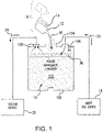
- Fig. 1 a partial view of an exemplary embodiment of a powder management container in accordance with the disclosure is shown in Fig. 1 and is designated generally by reference character 100.
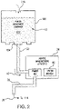
- FIGs. 2-7 Other embodiments of powder management containers and methods of making powder management containers in accordance with the disclosure, or aspects thereof, are provided in Figs. 2-7 , as will be described.
- the systems and methods described herein can be used for managing powder in additive manufacturing techniques, such as in metal article printing, though the present disclosure is not limited to metal article printing or to additive manufacturing techniques in general.
- Powder management container 100 is shown.
- Powder management container 100 is configured for storing a powder 10 for an additive manufacturing technique to reduce build set time, prevent contamination of powder 10 during storage, and provide lot association information to articles formed using the additive manufacturing technique.
- powder management container 100 is configured such that powder 10 can be can transferred to an interior 102 of powder management container 100.
- powder management container 100 is also configured such that powder 10 can be transferred from interior 102 of powder management container 100 to an additive manufacturing apparatus 12.
- powder management container 100 is additionally configured such that unused powder from an additive manufacturing build can be transferred to powder management container 100 for reuse in a subsequent build with lot tracking information, notwithstanding the powder having been previously cycle through an additive manufacturing apparatus.
- powder 10 is transferred into interior 102 of powder management container 100 through a first port 104 from ajar 12, interior 102 having a volume that is greater than that of jar 12. It is contemplated that jar 12 be a first jar and that powder from one or more second jar 14 be transferred into interior 102 of powder management container 100. As will be appreciated by those of skill in view of the present disclosure, lot information 16 associated with powder from first jar 12 and the one or more second jar 14 transfers with powder 10 to powder management container 100.
- powder 10 can be retained within interior 102 within an inert atmosphere 30.
- Inert atmosphere 30 can be provided by an inert gas source 18 disposed in fluid communication with interior 102 through a second port 106, inert gas source 18 providing an inert gas flow 20 through second port 106.
- suitable inert gases include nitrogen and argon, which tends to displace air due to relative density. As will be appreciated by those of skill in the art in view of the present disclosure, this separates humidity that may be present within the atmosphere 22 of powder management container 100 from powder 10.
- gas 24 from atmosphere 22 can be actively withdrawn from interior 102 as powder 10 is transferred to interior 102 of powder management container 100.
- a vacuum source 26 can be disposed in fluid communication with interior 102 through a third port 108, vacuum source 26 thereby withdrawing gas 24 from atmosphere 22 via third port 108 at a separate location from first port 104, powder 10 entering into interior 102 through first port 104.
- this prevents humidity that may be present in atmosphere 22 from contacting powder 10 as powder 10 enters powder management container 100.
- powder is transferred from powder management container 100 through a powder conduit 32 coupling first port 104 to an additive manufacturing apparatus 34.
- Transfer of powder 10 from powder management container 100 can be with the assistance of gravity, powder management container 100 being inverted such that first port 104 is below powder 10 relative to gravity, powder 10 thereby flowing to additive manufacturing apparatus 34 through powder conduit 32.
- powder management container 100 can include a backfill port 116.
- Backfill port 116 is arranged on an end of powder management container 100 opposite an end defining first port 104 and second port 106.
- Backfill port 116 is configured for placing interior 102 in fluid communication with the external environment once powder management container 100 is inverted, gas from the external environment thereby flowing into interior 102 through backfill port 116.
- backfilling interior through backfill port 116 can simplify transfer of powder 10 from powder management container 100 as powder 10 is less likely to bridge within interior 102 of powder management container 100.
- Second powder management container 114 is similar to powder management container 100 and is additionally connected to additive manufacturing apparatus 34 such that unused powder portion 36 transfers to second powder management container 114 via a reuse conduit 38.
- a portion of the powder supplied to an additive manufacturing apparatus to form an additively manufactured article typically remains subsequent to the build process.
- This unused powder is typically collected for use in a subsequent build, typically through a powder reuse module 40. While generally suitable for its intended purpose, use of powder recycle module can cause intermixing of the lot(s) from a prior build in a subsequent build. This can compromise the integrity of the lot tracking information associated with the subsequent build.
- unused powder portion 36 is transferred to second powder management container 114. This prevents powder from prior lots run through additive manufacturing apparatus 34 from intermixing with powder 10 and causes lot information 16 (shown in Fig. 1 ) to follow unused powder portion 36 to second powder management container 114. In certain embodiments transfer to interior 112 occurs by bypassing powder recycle module 28, unused powder portion 36 thereby not traversing powder reuse module 40. As will be appreciated, residual powder from prior builds captive within powder reuse module 40 also remains separate from unused powder portion 36.
- unused powder portion 36 can be transferred to interior 112 of second powder management container 114 under an inert atmosphere 110, inert atmosphere 110 established by inert gas 42 provided by inert gas source 18. It is also contemplated that gas 44 from within interior 112 can be withdrawn by vacuum source 26, thereby preventing humidity that may be present within gas 44 from contaminating unused powder portion 36 as unused powder portion 36 enters interior 112 as gas 44 exits interior 112.
- Powder management container 100 includes a keg body 118.
- Keg body 118 has a first end 120, a second end 122, and a body segment 124 extending between first end 120 and second end 122.
- Keg body 118 bounds interior 102 (shown in Fig. 2 ) and is configured for storing a powder, e.g., a metallic powder 10 (shown in Fig. 1 ), for use in additive manufacturing apparatus 34 (shown in Fig. 2 ).
- Keg body 118 defines first port 104.
- First port 104 is located on first end 120 of keg body 118, is fluidly coupled to keg body interior 102, and is configured for transferring powder 10 into and from interior 102 of keg body 118. More particularly, first port 104 is configured to receive powder 10 from one or more powder jars, e.g., jar 12 (shown in Fig. 1 ), and/or unused powder portion 36 (shown in Fig. 2 ) from additive manufacturing apparatus 34 for storage and/or re-use in a subsequent build operation. The unused powder can be stored within powder management container 100 in association with a lot identifier, e.g., lot information 16 (shown in Fig. 1 ), of powder 10.
- Keg body 118 also defines second port 106.
- Second port 106 is located on first end 120 of keg body 118, is fluidly coupled to keg body interior 102, and is configured for controlling atmosphere 22 (shown in Fig. 1 ) within keg body interior 102.
- second port 106 is offset from first port 104 to provide spatial separation and prevent intermixing of gas 24 exiting keg body interior 102 and powder 10 entering keg body interior 102 as well as placing vacuum source 26 (shown in Fig. 1 ) or inert gas source 18 (shown in Fig. 1 ) in fluid communication with keg body interior 102.
- Keg body 118 additionally defines third port 108.
- Third port 108 is located on first end 120 of keg body 118, is fluidly coupled to keg body interior 102, and is configured for controlling atmosphere 22 within keg body interior 102 in cooperation with second port 106.
- third port 108 is offset from first port 104.
- keg body interior 102 can be placed in fluid communication with vacuum source 26 or inert gas source 18 while the other of with a vacuum source 26 or inert gas source 18 is in fluid communication with keg body interior 102 without gas exiting from interior 112 contaminating powder 10 as it enters powder management container 100.
- keg body 118 conforms dimensionally to a standard beverage keg.
- Keg body 118 can be a commodity-type keg body, keg body 118 dimensionally conforming to US keg, DIN keg, or Euro keg standards prior to modification for power storage, e.g., below port 108 and port 106 as shown in Fig. 5 relative to the top of the drawing figure.
- keg body interior 112 has a volume that is between about 5 liters (1.32 gallons) and about 60 liters (15.5 gallons).
- keg body 118 can conform to the dimensions of a one-half barrel keg and have a volume of about 60 liters (15.5 gallons)
- keg body 118 can conform to the dimensions of a one-quarter barrel keg and have a volume of about 30 liters (7.75 gallons).
- Dimensional conformity with standard beverage kegs allows for handling powder management container 100 with existing material handling equipment as well as providing volumes of powder commensurate with that required for builds of additively manufactured articles, such as fuel nozzles by way of non-limiting examples.
- a first aperture can be created by removing a first portion of the keg body extending about the Sankey female-threaded portion of the keg, removing a second portion of the keg body offset from the first aperture, and removing a third portion of the keg body offset from the first aperture and laterally offset from the second aperture.
- the first port can then be welded to the keg body in the first port, the second port welded to the keg body in the second aperture, and the third port welded to the keg body in the third aperture.
- Welding the ports to the keg body can include defining food-grade polished welds in the keg body, food-grade polished weld preventing lot intermixing by preventing capture of powder in the weld as originally formed.
- Cap 149 includes a flat plate body that is seated on first port 104 and secured thereto by a tri-clamp sanitary fitting 152. Cap 149 provides sealing to keg body 118, allowing keg body 118 to be sealed for storage purposes. It is contemplated that cap 149 be emplaced on first port 104 and a vacuum pulled on the interior of keg body118 so that an inert gas can be backfilled into keg body 118. This allows for powder to be easily stored between uses in keg body 118 as well allowing for ready connection to other various systems for filling and discharge of the powder.
- Keg body 118 has a wall thickness 138.
- wall thickness 138 is equivalent to the wall thickness of a commodity-type beverage (e.g., beer) keg, as shown with solid line 142.
- wall thickness 138 can be greater than the wall thickness of a commodity-type beverage keg, as shown with dashed line 140.
- certain powdered metals can be more dense than beverage material or other products intended for commodity-type kegs. Greater wall thickness may allow transfer of powder into powder management container 100 with greater weights than otherwise possible without damaging keg body 118.
- First port 104 defines a flow area 126 with a width 128.
- Width 128 is greater than a width 130 of a flow area 132 defined by second port 106.
- Width 128 is also greater than a width 134 of a flow area 136 defined by third port 108.
- width 128 is about four inches (10.2 centimeters). Widths of this size allow for metallic powders, e.g., powder 10 (shown in Fig. 1 ), to flow freely through first port 104 without bridging. This can eliminate the need to assist powder flow with an external pressure source and/or mechanical vibration.
- keg body 118 is formed from stainless steel 144 and includes one or more weld 146. As stainless steel 144 is relatively inert, stainless steel 144 reduces the likelihood that the material forming keg body 118 will contaminate powder 10 (shown in Fig. 1 ) contained within powder management container 100.
- keg body 118 can be formed from an aluminum or aluminum alloy 150. Use of aluminum or aluminum alloy can reduce the chance of contaminating aluminum powders with material eroded from the interior surface of keg body 118.
- Weld 146 is a food-grade polished weld. As will be appreciated by those of skill in the art in view of the present disclosure, food-grade polished welds resist capture of particulate, reducing the likelihood of intermixing powders from prior builds, potentially from other lots, into powder subsequently introduced into powder management container 100.
- Tri-clamp flange 148 can be coupled to first port 104. Tri-clamp flange 148 is fluidly coupled to keg body 118 through first port 104. Tri-clamp flange 148 allows for connection of powder management container 100 to additive manufacturing apparatus 34 (shown in Fig. 1 ) with standardized fittings and without specialized tools, simplifying operation of additive manufacturing apparatus. Alternatively, cap 149 can be secured to tri-clamp flange 148 by tri-clamp sanitary fitting 152.
- a second tri-clamp sanitary fitting 153, a threaded fitting 154, or a Klein Flansche (KF) fitting 156 can be coupled to keg body 118 at second port 106. More particularly, tri-clamp sanitary fitting 152, threaded fitting 154, or KF fitting 156 can be coupled to keg body 118 at second port 106 such that second port 106 fluidly couples tri-clamp sanitary fitting 152, threaded fitting 154, or KF fitting 156 to keg body interior 102 through second port 106.
- Use of tri-clamp sanitary fitting 152, threaded fitting 154, or KF fitting 156 simplifies connection of inert gas source 18 (shown in Fig. 1 ) to powder management container 100.
- a tri-clamp sanitary fitting 158, a threaded fitting 160, or a KF fitting 162 can be coupled to keg body 118 at third port 108. More particularly, tri-clamp sanitary fitting 158, threaded fitting 160, or KF fitting 162 can be coupled to keg body 118 at third port 108 such that third port 108 fluidly couples tri-clamp sanitary fitting 158, threaded fitting 160, or KF fitting 162 to keg body interior 102 through third port 108.
- Use of tri-clamp sanitary fitting 158, threaded fitting 160, or KF fitting 162 simplifies connection of vacuum source 26 (shown in Fig. 1 ) to powder management container 100.
- a method 200 of making a powder management container e.g., powder management container 100 (shown in Fig. 1 ), as shown.
- a keg body e.g., keg body 118 (shown in Fig. 1 ) is provided.
- the keg body can be a commodity-type keg body, as shown with box 212.
- a Sankey valve seat can be removed from the keg body, as shown by box 220.
- a first port e.g., first port 104 (shown in Fig.
- the first port can be coupled by a weld, e.g., weld 146 (shown in Fig. 5 ), as shown with box 232.
- a second port e.g., second port 106 (shown in Fig 1 ) can be coupled to the keg body, as shown by box 240.
- the second port can be welded or threaded to the keg body, as shown by box 242.
- a third port, e.g., third port 108 (shown in Fig.
- a backfill port e.g., backfill port 116 (shown in Fig. 2 ), can be coupled to the keg body and placed in fluid communication with the keg body interior for transferring powder from the keg body interior, as shown with box 260.
- the backfill port can be welded to the keg body as shown by box 262.
- Method 700 includes coupling a first port of a powder management container, e.g., first port 104 (shown in Fig. 1 ), to an additive manufacturing apparatus, e.g., additive manufacturing apparatus 34 (shown in Fig. 2 ), as shown by box 330.
- a second port of the powder management container e.g., second port 106 (shown in Fig. 1 ) is coupled to an inert gas source, e.g., inert gas source 18 (shown in Fig. 1 ), as shown by box 350.
- Inert gas is flowed into the powder management container, as shown by box 352.
- a third port e.g., third port 108 (shown in Fig. 1 ), is connected to a vacuum source, e.g., vacuum source 26 (shown in Fig. 1 ).
- Powder is then transferred either into the powder management container from the additive manufacturing apparatus as shown in Fig. 3 or powder transferred into the powder management container from one or more powder jars, e.g., powder jar 12 (shown in Fig. 1 ), as shown with box 310.
- the powder transferred into the powder management container can be from a single powder lot, as shown with box 312.
- the powder transferred into the powder management container can be from a plurality of powder lots, as shown with box 314.
Landscapes
- Engineering & Computer Science (AREA)
- Chemical & Material Sciences (AREA)
- Materials Engineering (AREA)
- Mechanical Engineering (AREA)
- Manufacturing & Machinery (AREA)
- Physics & Mathematics (AREA)
- Optics & Photonics (AREA)
- Dispersion Chemistry (AREA)
- Powder Metallurgy (AREA)
- Packages (AREA)
Claims (15)
- Pulvermanagementsystem, umfassend:eine additive Fertigungsmaschine;einen ersten Pulvermanagementbehälter und einen zweiten Pulvermanagementbehälter, die jeweils in Fluidverbindung mit der additiven Fertigungsmaschine stehen, wobei der erste Behälter und der zweite Behälter jeweils Folgendes umfassen:einen Fasskörper (118), der einen Innenraum zum Speichern eines Metallpulvers aufweist;einen ersten Anschluss (104), der durch den Fasskörper (118) definiert ist, wobei der erste Anschluss (104) in Fluidverbindung mit dem Innenraum des Fasskörpers (118) zum Transportieren von Pulver in den und aus dem Innenraum (102) des Fasskörpers (118) steht; undeinen zweiten Anschluss (106), der durch den Fasskörper (118) definiert ist, wobei der zweite Anschluss in Fluidverbindung mit dem Innenraum (102) des Fasskörpers zum Steuern der Atmosphäre innerhalb des Innenraums des Fasskörpers (118) steht, und dadurch gekennzeichnet, dass sie ferner Folgendes umfasseneinen dritten Anschluss (108), der durch den Fasskörper (118) definiert ist, wobei der dritte Anschluss (108) von dem ersten Anschluss (104) und dem zweiten Anschluss (106) versetzt ist, wobei der dritte Anschluss (108) in Fluidverbindung mit dem Innenraum des Fasskörpers zum Steuern der Atmosphäre innerhalb des Innenraums des Fasskörpers (118) steht;wobei der erste Pulvermanagementbehälter mit einer Pulverleitung zum Transportieren von Baupulver zu der additiven Fertigungsmaschine verbunden ist; undwobei der zweite Pulvermanagementbehälter mit einer Wiederverwendungsleitung der additiven Fertigungsmaschine zum Speichern nicht verwendeten Pulvers verbunden ist.
- Pulvermanagementsystem nach Anspruch 1, wobei der Fasskörper (118) ein Getränkefass für Waren unter dem ersten Anschluss (104) und dem zweiten Anschluss (106) ist, wobei der Fasskörper für Waren vor der Modifikation zur Pulverspeicherung maßlich US-, DIN- oder Euro-Fassnormen entspricht.
- Pulvermanagementsystem nach Anspruch 1 oder 2, wobei der Innenraum (102) des Fasskörpers (118) ein Volumen aufweist, das zwischen etwa 5 Liter (1,32 Gallonen) und etwa 60 Liter (15,5 Gallonen) beträgt.
- Pulvermanagementsystem nach Anspruch 1, 2 oder 3, wobei der Fasskörper (118) eine Wanddicke aufweist, die größer als eine Dicke eines Fasses für Waren eines im Wesentlichen vergleichbaren Volumens ist, wobei der Fasskörper für Waren vor der Modifikation zur Pulverspeicherung maßlich US-, DIN- oder Euro-Fassnormen entspricht.
- Pulvermanagementsystem nach einem der vorstehenden Ansprüche, wobei der Fasskörper (118) aus Aluminium, einer Aluminiumlegierung oder rostfreiem Stahl hergestellt ist; und/oder wobei der Fasskörper (118) einen oder mehrere in Lebensmittelqualität polierte Schweißnähte beinhaltet, wobei die in Lebensmittelqualität polierte Schweißnaht so konfiguriert ist, dass sie eine Chargenvermischung durch Verhindern eines Festhaltens von Pulver in der Schweißnaht, so wie sie ursprünglich ausgebildet ist, verhindert.
- Pulvermanagementsystem nach einem der vorstehenden Ansprüche, wobei der erste Anschluss (104) zentral an einem Ende des Fasskörpers (118) angeordnet ist oder wobei der erste Anschluss (104) und der zweite Anschluss an einem ersten Ende des Fasskörpers (118) angeordnet sind.
- Pulvermanagementsystem nach einem der vorstehenden Ansprüche, wobei der erste Anschluss (104) eine Strömungsfläche aufweist, die größer als eine Strömungsfläche des zweiten Anschlusses (106) ist.
- Pulvermanagementsystem nach einem der vorstehenden Ansprüche, ferner einen Tri-Clamp-Flansch umfassend, der mit dem ersten Anschluss (104) gekoppelt ist und in Fluidverbindung mit dem Innenraum des Fasskörpers (118) über den ersten Anschluss (104) steht, oder ferner einen Tri-Clamp-Sanitär-, einen Gewindeanschluss oder einen Klein-Flansch-Anschluss, der mit dem Fasskörper (118) gekoppelt ist und in Fluidverbindung mit dem Fasskörperinnenraum (102) über den zweiten Anschluss (106) steht, umfassend.
- Pulvermanagementsystem nach einem der vorstehenden Ansprüche, wobei der erste Anschluss (104) eine Strömungsfläche mit einer Breite, die etwa 10,2 Zentimeter (4 Zoll) beträgt, aufweist.
- Pulvermanagementsystem nach einem der vorstehenden Ansprüche, wobei der dritte Anschluss (108) eine Strömungsfläche aufweist, die kleiner als eine Strömungsfläche des ersten Anschlusses (104) ist, und/oder ferner einen Tri-Clamp-Sanitär- , einen Gewindeanschluss oder einen Klein-Flansch-Anschluss umfassend, der mit dem Fasskörper gekoppelt ist und in Fluidverbindung mit dem Fasskörperinnenraum (102) über den dritten Anschluss (108) steht.
- Pulvermanagementsystem nach einem der vorstehenden Ansprüche, wobei der erste Anschluss (104) und der zweite Anschluss (106) an einem ersten Ende des Fasskörpers (118) angeordnet sind, und ferner einen Auffüllanschluss (116), der durch den Fasskörper (118) definiert ist, umfassend, wobei der Auffüllanschluss an einem zweiten Ende des Fasskörpers (118) gegenüber dem ersten Ende des Fasskörpers (118) angeordnet ist.
- Pulvermanagementsystem nach einem der vorstehenden Ansprüche, wobei der Fasskörper (118) ein Fasskörper für Waren ist, wobei der Innenraum (102) des Fasskörpers (118) ein Volumen aufweist, das zwischen etwa 5 Liter (1,32 Gallonen) und etwa 60 Liter (15,5 Gallonen) beträgt, wobei der Pulvermanagementbehälter ferner Folgendes umfasst:einen Tri-Clamp-Flansch, der mit dem Fasskörper (118) gekoppelt ist und in Fluidverbindung mit dem Innenraum des Fasskörpers durch den ersten Anschluss (104) steht, wobei der erste Anschluss (104) eine 10,2 Zentimeter (4 Zoll) breite Strömungsfläche aufweist; undeinen Auffüllanschluss (112), der an einem zweiten Ende des Fasskörpers (118) gegenüber dem ersten Ende des Fasskörpers (118) angeordnet ist.
- Verfahren zum Herstellen eines Pulvermanagementbehälters, der mit dem Pulvermanagementsystem nach einem der Ansprüche 1 bis 12 verbunden ist, umfassend:Entfernen eines Sankey-Ventils von einem Fasskörper (118);Koppeln eines ersten Anschlusses (104) mit dem Fasskörper (118), wobei der erste Anschluss (104) in Fluidverbindung mit einem Innenraum des Fasskörpers (118) zum Transportieren von Pulver in den und aus dem Fasskörperinnenraum (102) steht; undKoppeln eines zweiten Anschlusses (106) mit dem Fasskörper (118), wobei der zweite Anschluss (106) in Fluidverbindung mit dem Innenraum des Fasskörpers (118) zum Steuern der Atmosphäre innerhalb des Fasskörperinnenraums (102) steht, und gekennzeichnet durchKoppeln eines dritten Anschlusses mit dem Fasskörper (118), wobei der dritte Anschluss (106) in Fluidverbindung mit dem Innenraum des Fasskörpers (118) zum Steuern der Atmosphäre innerhalb des Fasskörperinnenraums (102) steht.
- Verfahren nach Anspruch 13, ferner Folgendes umfassend:
Koppeln eines Auffüllanschlusses mit dem Fasskörper (118), wobei der Auffüllanschluss (112) in Fluidverbindung mit dem Innenraum (102) des Fasskörpers (118) zum Transportieren von Pulver aus dem Fasskörperinnenraum (102) steht. - Verfahren zum Managen von Pulver für ein additives Fertigungsverfahren, umfassend:Koppeln eines ersten Anschlusses (104) eines Fasskörpers (118) mit einem additiven Fertigungsapparat, wobei der erste Anschluss (104) in Fluidverbindung mit einem Innenraum (102) des Fasskörpers (118) angeordnet ist;Koppeln eines zweiten Anschlusses (106) des Fasskörpers (118) mit einer Vakuum- oder Inertgasquelle, wobei der zweite Anschluss in Fluidverbindung mit dem Innenraum des Fasskörpers angeordnet ist; undgekennzeichnet durchKoppeln eines dritten Anschlusses an den Fasskörper (118), wobei der dritte Anschluss (106) in Fluidverbindung mit dem Innenraum des Fasskörpers (118) zum Steuern der Atmosphäre innerhalb des Fasskörperinnenraums ist;Transportieren von Pulver in den Fasskörper (118) von dem additiven Fertigungsapparat; undSteuern der Atmosphäre innerhalb des Innenraums (102) des Fasskörpers (118) durch Anlegen eines Vakuums oder Strömenlassen eines Inertgases durch den zweiten Anschluss (106).
Applications Claiming Priority (1)
| Application Number | Priority Date | Filing Date | Title |
|---|---|---|---|
| US15/888,854 US20190241378A1 (en) | 2018-02-05 | 2018-02-05 | Powder management containers |
Publications (2)
| Publication Number | Publication Date |
|---|---|
| EP3520932A1 EP3520932A1 (de) | 2019-08-07 |
| EP3520932B1 true EP3520932B1 (de) | 2022-03-30 |
Family
ID=65324191
Family Applications (1)
| Application Number | Title | Priority Date | Filing Date |
|---|---|---|---|
| EP19155420.3A Active EP3520932B1 (de) | 2018-02-05 | 2019-02-05 | Pulvermanagementsystem, verfahren zur herstellung eines pulvermanagementbehälters und verfahren zum verwalten von pulver für eine additive herstellungstechnik |
Country Status (2)
| Country | Link |
|---|---|
| US (1) | US20190241378A1 (de) |
| EP (1) | EP3520932B1 (de) |
Families Citing this family (7)
| Publication number | Priority date | Publication date | Assignee | Title |
|---|---|---|---|---|
| US11104073B2 (en) * | 2016-05-12 | 2021-08-31 | Hewlett-Packard Development Company, L.P. | Build material container |
| EP3774294A4 (de) * | 2018-09-28 | 2021-11-17 | Hewlett-Packard Development Company, L.P. | 3d-drucksystem |
| GB2589825B (en) * | 2019-10-02 | 2024-05-29 | Lpw Technology Ltd | A docking arrangement for an additive manufacturing process |
| TWI719710B (zh) * | 2019-11-13 | 2021-02-21 | 財團法人工業技術研究院 | 環控粉末處理系統及其方法 |
| US11718033B2 (en) * | 2019-11-15 | 2023-08-08 | Desktop Metal, Inc. | Systems and methods for powder recovery, cleaning, and blending, for additive manufacturing |
| PL240330B1 (pl) * | 2020-01-28 | 2022-03-14 | Siec Badawcza Lukasiewicz Instytut Tech Eksploatacji | Zbiornik do kondycjonowania i precyzyjnego dozowania pyłu do atmosfery testowej urządzenia do badania odporności na oddziaływanie pyłów |
| GB2596816B (en) * | 2020-07-07 | 2024-08-07 | Lpw Technology Ltd | Arrangements for blanking a coupling member |
Family Cites Families (3)
| Publication number | Priority date | Publication date | Assignee | Title |
|---|---|---|---|---|
| US10370237B2 (en) * | 2012-10-10 | 2019-08-06 | Raymond Wilson Blackburn | Fluid dispenser with isolation membrane |
| US10814387B2 (en) * | 2015-08-03 | 2020-10-27 | General Electric Company | Powder recirculating additive manufacturing apparatus and method |
| EP3265294B1 (de) * | 2016-05-12 | 2020-10-07 | Hewlett-Packard Development Company, L.P. | Baumaterialbehälter |
-
2018
- 2018-02-05 US US15/888,854 patent/US20190241378A1/en not_active Abandoned
-
2019
- 2019-02-05 EP EP19155420.3A patent/EP3520932B1/de active Active
Non-Patent Citations (1)
| Title |
|---|
| None * |
Also Published As
| Publication number | Publication date |
|---|---|
| EP3520932A1 (de) | 2019-08-07 |
| US20190241378A1 (en) | 2019-08-08 |
Similar Documents
| Publication | Publication Date | Title |
|---|---|---|
| EP3520932A1 (de) | Pulvermanagementbehälter | |
| CN100564173C (zh) | 用于导管的气体充装和密封的方法和装置 | |
| US11660675B2 (en) | Cover arrangements for machines for manufacturing three-dimensional components | |
| US5526956A (en) | Liquid chemical dispensing and recirculating system | |
| EP0138718B1 (de) | Verfahren und Vorrichtung für die Versorgung mit flüssigem Dotierungsstoff aus einem hermetischen Pfandfass | |
| EP3054454B1 (de) | Füllbehälter zum aufbewahren von gefährlichen abfallmaterialien | |
| EP3425639B1 (de) | Fülleinrichtungen, systeme und verfahren zum übertragen von gefährlichen abfällen in einen versiegelbaren behälter | |
| TW201524886A (zh) | 高黏度液體含納材料的壓力分配裝置及方法 | |
| US11951541B2 (en) | Robotized ladle turret system | |
| KR20050085839A (ko) | 밀폐 용기 제작방법, 상기 밀폐 용기 및 그 구성 부재 | |
| EP4221921A2 (de) | Impulsübertragung für grossflächiges metallfusionssystem | |
| JP5725266B2 (ja) | 薬液収納容器 | |
| US11511487B2 (en) | System for producing an object by means of additive manufacturing | |
| JPH0646239B2 (ja) | 放射性金属廃棄物を溶融炉へ装入し、同廃棄物を溶融するための方法及び装置 | |
| CN109605739A (zh) | 用于添加式地制造三维物体的设备的粉末模块装置 | |
| RU2557110C1 (ru) | Разработка модульного комплекса технологического оборудования для хранения опасных отходов | |
| US20250145317A1 (en) | Packaging device, packaging machine, filling system, and method for operating a packaging device | |
| WO1994021550A1 (en) | Closure for fluid containers | |
| JP6516152B2 (ja) | 液体排出方法 | |
| WO2026003744A1 (en) | Device, method and system for filling semi-finished batteries | |
| WO2026003745A1 (en) | Device, method and system for filling semi-finished batteries | |
| JP3621387B2 (ja) | 溶融金属供給用容器 | |
| JP2009046147A (ja) | 高粘度液体の取り扱い方法 | |
| HK1133625B (en) | A container blank intended for a container of a collapsible type | |
| CN114475740A (zh) | 一种液态金属锡转运设备 |
Legal Events
| Date | Code | Title | Description |
|---|---|---|---|
| PUAI | Public reference made under article 153(3) epc to a published international application that has entered the european phase |
Free format text: ORIGINAL CODE: 0009012 |
|
| STAA | Information on the status of an ep patent application or granted ep patent |
Free format text: STATUS: THE APPLICATION HAS BEEN PUBLISHED |
|
| AK | Designated contracting states |
Kind code of ref document: A1 Designated state(s): AL AT BE BG CH CY CZ DE DK EE ES FI FR GB GR HR HU IE IS IT LI LT LU LV MC MK MT NL NO PL PT RO RS SE SI SK SM TR |
|
| AX | Request for extension of the european patent |
Extension state: BA ME |
|
| STAA | Information on the status of an ep patent application or granted ep patent |
Free format text: STATUS: REQUEST FOR EXAMINATION WAS MADE |
|
| 17P | Request for examination filed |
Effective date: 20191126 |
|
| RBV | Designated contracting states (corrected) |
Designated state(s): AL AT BE BG CH CY CZ DE DK EE ES FI FR GB GR HR HU IE IS IT LI LT LU LV MC MK MT NL NO PL PT RO RS SE SI SK SM TR |
|
| STAA | Information on the status of an ep patent application or granted ep patent |
Free format text: STATUS: EXAMINATION IS IN PROGRESS |
|
| 17Q | First examination report despatched |
Effective date: 20200618 |
|
| REG | Reference to a national code |
Ref country code: DE Ref legal event code: R079 Ref document number: 602019012914 Country of ref document: DE Free format text: PREVIOUS MAIN CLASS: B22F0003105000 Ipc: B29C0064255000 |
|
| RIC1 | Information provided on ipc code assigned before grant |
Ipc: B29C 64/255 20170101AFI20210729BHEP Ipc: B33Y 30/00 20150101ALI20210729BHEP Ipc: B65D 8/00 20060101ALI20210729BHEP Ipc: B65D 6/40 20060101ALI20210729BHEP Ipc: B65D 83/14 20060101ALI20210729BHEP Ipc: B33Y 40/00 20200101ALI20210729BHEP Ipc: B22F 10/20 20210101ALI20210729BHEP Ipc: B22F 10/70 20210101ALI20210729BHEP Ipc: B22F 12/00 20210101ALI20210729BHEP Ipc: B29C 64/153 20170101ALN20210729BHEP Ipc: B33Y 10/00 20150101ALN20210729BHEP |
|
| RIC1 | Information provided on ipc code assigned before grant |
Ipc: B33Y 10/00 20150101ALN20210805BHEP Ipc: B29C 64/153 20170101ALN20210805BHEP Ipc: B22F 12/00 20210101ALI20210805BHEP Ipc: B22F 10/70 20210101ALI20210805BHEP Ipc: B22F 10/20 20210101ALI20210805BHEP Ipc: B33Y 40/00 20200101ALI20210805BHEP Ipc: B65D 83/14 20060101ALI20210805BHEP Ipc: B65D 6/40 20060101ALI20210805BHEP Ipc: B65D 8/00 20060101ALI20210805BHEP Ipc: B33Y 30/00 20150101ALI20210805BHEP Ipc: B29C 64/255 20170101AFI20210805BHEP |
|
| GRAP | Despatch of communication of intention to grant a patent |
Free format text: ORIGINAL CODE: EPIDOSNIGR1 |
|
| STAA | Information on the status of an ep patent application or granted ep patent |
Free format text: STATUS: GRANT OF PATENT IS INTENDED |
|
| INTG | Intention to grant announced |
Effective date: 20210916 |
|
| RAP3 | Party data changed (applicant data changed or rights of an application transferred) |
Owner name: DELAVAN INC |
|
| GRAS | Grant fee paid |
Free format text: ORIGINAL CODE: EPIDOSNIGR3 |
|
| GRAA | (expected) grant |
Free format text: ORIGINAL CODE: 0009210 |
|
| STAA | Information on the status of an ep patent application or granted ep patent |
Free format text: STATUS: THE PATENT HAS BEEN GRANTED |
|
| AK | Designated contracting states |
Kind code of ref document: B1 Designated state(s): AL AT BE BG CH CY CZ DE DK EE ES FI FR GB GR HR HU IE IS IT LI LT LU LV MC MK MT NL NO PL PT RO RS SE SI SK SM TR |
|
| REG | Reference to a national code |
Ref country code: GB Ref legal event code: FG4D |
|
| REG | Reference to a national code |
Ref country code: CH Ref legal event code: EP |
|
| REG | Reference to a national code |
Ref country code: DE Ref legal event code: R096 Ref document number: 602019012914 Country of ref document: DE |
|
| REG | Reference to a national code |
Ref country code: AT Ref legal event code: REF Ref document number: 1478785 Country of ref document: AT Kind code of ref document: T Effective date: 20220415 |
|
| REG | Reference to a national code |
Ref country code: IE Ref legal event code: FG4D |
|
| RAP4 | Party data changed (patent owner data changed or rights of a patent transferred) |
Owner name: COLLINS ENGINE NOZZLES, INC. |
|
| REG | Reference to a national code |
Ref country code: DE Ref legal event code: R081 Ref document number: 602019012914 Country of ref document: DE Owner name: COLLINS ENGINE NOZZLES, INC., WEST DES MOINES, US Free format text: FORMER OWNER: DELAVAN, INC., WEST DES MOINES, IA, US |
|
| REG | Reference to a national code |
Ref country code: LT Ref legal event code: MG9D |
|
| PG25 | Lapsed in a contracting state [announced via postgrant information from national office to epo] |
Ref country code: SE Free format text: LAPSE BECAUSE OF FAILURE TO SUBMIT A TRANSLATION OF THE DESCRIPTION OR TO PAY THE FEE WITHIN THE PRESCRIBED TIME-LIMIT Effective date: 20220330 Ref country code: RS Free format text: LAPSE BECAUSE OF FAILURE TO SUBMIT A TRANSLATION OF THE DESCRIPTION OR TO PAY THE FEE WITHIN THE PRESCRIBED TIME-LIMIT Effective date: 20220330 Ref country code: NO Free format text: LAPSE BECAUSE OF FAILURE TO SUBMIT A TRANSLATION OF THE DESCRIPTION OR TO PAY THE FEE WITHIN THE PRESCRIBED TIME-LIMIT Effective date: 20220630 Ref country code: LT Free format text: LAPSE BECAUSE OF FAILURE TO SUBMIT A TRANSLATION OF THE DESCRIPTION OR TO PAY THE FEE WITHIN THE PRESCRIBED TIME-LIMIT Effective date: 20220330 Ref country code: HR Free format text: LAPSE BECAUSE OF FAILURE TO SUBMIT A TRANSLATION OF THE DESCRIPTION OR TO PAY THE FEE WITHIN THE PRESCRIBED TIME-LIMIT Effective date: 20220330 Ref country code: BG Free format text: LAPSE BECAUSE OF FAILURE TO SUBMIT A TRANSLATION OF THE DESCRIPTION OR TO PAY THE FEE WITHIN THE PRESCRIBED TIME-LIMIT Effective date: 20220630 |
|
| REG | Reference to a national code |
Ref country code: NL Ref legal event code: MP Effective date: 20220330 |
|
| REG | Reference to a national code |
Ref country code: AT Ref legal event code: MK05 Ref document number: 1478785 Country of ref document: AT Kind code of ref document: T Effective date: 20220330 |
|
| PG25 | Lapsed in a contracting state [announced via postgrant information from national office to epo] |
Ref country code: LV Free format text: LAPSE BECAUSE OF FAILURE TO SUBMIT A TRANSLATION OF THE DESCRIPTION OR TO PAY THE FEE WITHIN THE PRESCRIBED TIME-LIMIT Effective date: 20220330 Ref country code: GR Free format text: LAPSE BECAUSE OF FAILURE TO SUBMIT A TRANSLATION OF THE DESCRIPTION OR TO PAY THE FEE WITHIN THE PRESCRIBED TIME-LIMIT Effective date: 20220701 Ref country code: FI Free format text: LAPSE BECAUSE OF FAILURE TO SUBMIT A TRANSLATION OF THE DESCRIPTION OR TO PAY THE FEE WITHIN THE PRESCRIBED TIME-LIMIT Effective date: 20220330 |
|
| PG25 | Lapsed in a contracting state [announced via postgrant information from national office to epo] |
Ref country code: NL Free format text: LAPSE BECAUSE OF FAILURE TO SUBMIT A TRANSLATION OF THE DESCRIPTION OR TO PAY THE FEE WITHIN THE PRESCRIBED TIME-LIMIT Effective date: 20220330 |
|
| PG25 | Lapsed in a contracting state [announced via postgrant information from national office to epo] |
Ref country code: SM Free format text: LAPSE BECAUSE OF FAILURE TO SUBMIT A TRANSLATION OF THE DESCRIPTION OR TO PAY THE FEE WITHIN THE PRESCRIBED TIME-LIMIT Effective date: 20220330 Ref country code: SK Free format text: LAPSE BECAUSE OF FAILURE TO SUBMIT A TRANSLATION OF THE DESCRIPTION OR TO PAY THE FEE WITHIN THE PRESCRIBED TIME-LIMIT Effective date: 20220330 Ref country code: RO Free format text: LAPSE BECAUSE OF FAILURE TO SUBMIT A TRANSLATION OF THE DESCRIPTION OR TO PAY THE FEE WITHIN THE PRESCRIBED TIME-LIMIT Effective date: 20220330 Ref country code: PT Free format text: LAPSE BECAUSE OF FAILURE TO SUBMIT A TRANSLATION OF THE DESCRIPTION OR TO PAY THE FEE WITHIN THE PRESCRIBED TIME-LIMIT Effective date: 20220801 Ref country code: ES Free format text: LAPSE BECAUSE OF FAILURE TO SUBMIT A TRANSLATION OF THE DESCRIPTION OR TO PAY THE FEE WITHIN THE PRESCRIBED TIME-LIMIT Effective date: 20220330 Ref country code: EE Free format text: LAPSE BECAUSE OF FAILURE TO SUBMIT A TRANSLATION OF THE DESCRIPTION OR TO PAY THE FEE WITHIN THE PRESCRIBED TIME-LIMIT Effective date: 20220330 Ref country code: CZ Free format text: LAPSE BECAUSE OF FAILURE TO SUBMIT A TRANSLATION OF THE DESCRIPTION OR TO PAY THE FEE WITHIN THE PRESCRIBED TIME-LIMIT Effective date: 20220330 Ref country code: AT Free format text: LAPSE BECAUSE OF FAILURE TO SUBMIT A TRANSLATION OF THE DESCRIPTION OR TO PAY THE FEE WITHIN THE PRESCRIBED TIME-LIMIT Effective date: 20220330 |
|
| PG25 | Lapsed in a contracting state [announced via postgrant information from national office to epo] |
Ref country code: PL Free format text: LAPSE BECAUSE OF FAILURE TO SUBMIT A TRANSLATION OF THE DESCRIPTION OR TO PAY THE FEE WITHIN THE PRESCRIBED TIME-LIMIT Effective date: 20220330 Ref country code: IS Free format text: LAPSE BECAUSE OF FAILURE TO SUBMIT A TRANSLATION OF THE DESCRIPTION OR TO PAY THE FEE WITHIN THE PRESCRIBED TIME-LIMIT Effective date: 20220730 Ref country code: AL Free format text: LAPSE BECAUSE OF FAILURE TO SUBMIT A TRANSLATION OF THE DESCRIPTION OR TO PAY THE FEE WITHIN THE PRESCRIBED TIME-LIMIT Effective date: 20220330 |
|
| REG | Reference to a national code |
Ref country code: DE Ref legal event code: R097 Ref document number: 602019012914 Country of ref document: DE |
|
| PG25 | Lapsed in a contracting state [announced via postgrant information from national office to epo] |
Ref country code: DK Free format text: LAPSE BECAUSE OF FAILURE TO SUBMIT A TRANSLATION OF THE DESCRIPTION OR TO PAY THE FEE WITHIN THE PRESCRIBED TIME-LIMIT Effective date: 20220330 |
|
| PLBE | No opposition filed within time limit |
Free format text: ORIGINAL CODE: 0009261 |
|
| STAA | Information on the status of an ep patent application or granted ep patent |
Free format text: STATUS: NO OPPOSITION FILED WITHIN TIME LIMIT |
|
| 26N | No opposition filed |
Effective date: 20230103 |
|
| PG25 | Lapsed in a contracting state [announced via postgrant information from national office to epo] |
Ref country code: SI Free format text: LAPSE BECAUSE OF FAILURE TO SUBMIT A TRANSLATION OF THE DESCRIPTION OR TO PAY THE FEE WITHIN THE PRESCRIBED TIME-LIMIT Effective date: 20220330 |
|
| P01 | Opt-out of the competence of the unified patent court (upc) registered |
Effective date: 20230530 |
|
| PG25 | Lapsed in a contracting state [announced via postgrant information from national office to epo] |
Ref country code: IT Free format text: LAPSE BECAUSE OF FAILURE TO SUBMIT A TRANSLATION OF THE DESCRIPTION OR TO PAY THE FEE WITHIN THE PRESCRIBED TIME-LIMIT Effective date: 20220330 |
|
| PG25 | Lapsed in a contracting state [announced via postgrant information from national office to epo] |
Ref country code: MC Free format text: LAPSE BECAUSE OF FAILURE TO SUBMIT A TRANSLATION OF THE DESCRIPTION OR TO PAY THE FEE WITHIN THE PRESCRIBED TIME-LIMIT Effective date: 20220330 |
|
| REG | Reference to a national code |
Ref country code: CH Ref legal event code: PL |
|
| REG | Reference to a national code |
Ref country code: BE Ref legal event code: MM Effective date: 20230228 |
|
| PG25 | Lapsed in a contracting state [announced via postgrant information from national office to epo] |
Ref country code: LU Free format text: LAPSE BECAUSE OF NON-PAYMENT OF DUE FEES Effective date: 20230205 Ref country code: LI Free format text: LAPSE BECAUSE OF NON-PAYMENT OF DUE FEES Effective date: 20230228 Ref country code: CH Free format text: LAPSE BECAUSE OF NON-PAYMENT OF DUE FEES Effective date: 20230228 |
|
| REG | Reference to a national code |
Ref country code: IE Ref legal event code: MM4A |
|
| PG25 | Lapsed in a contracting state [announced via postgrant information from national office to epo] |
Ref country code: IE Free format text: LAPSE BECAUSE OF NON-PAYMENT OF DUE FEES Effective date: 20230205 |
|
| PG25 | Lapsed in a contracting state [announced via postgrant information from national office to epo] |
Ref country code: BE Free format text: LAPSE BECAUSE OF NON-PAYMENT OF DUE FEES Effective date: 20230228 |
|
| PGFP | Annual fee paid to national office [announced via postgrant information from national office to epo] |
Ref country code: DE Payment date: 20240123 Year of fee payment: 6 Ref country code: GB Payment date: 20240123 Year of fee payment: 6 |
|
| PGFP | Annual fee paid to national office [announced via postgrant information from national office to epo] |
Ref country code: FR Payment date: 20240123 Year of fee payment: 6 |
|
| PG25 | Lapsed in a contracting state [announced via postgrant information from national office to epo] |
Ref country code: CY Free format text: LAPSE BECAUSE OF FAILURE TO SUBMIT A TRANSLATION OF THE DESCRIPTION OR TO PAY THE FEE WITHIN THE PRESCRIBED TIME-LIMIT; INVALID AB INITIO Effective date: 20190205 |
|
| PG25 | Lapsed in a contracting state [announced via postgrant information from national office to epo] |
Ref country code: HU Free format text: LAPSE BECAUSE OF FAILURE TO SUBMIT A TRANSLATION OF THE DESCRIPTION OR TO PAY THE FEE WITHIN THE PRESCRIBED TIME-LIMIT; INVALID AB INITIO Effective date: 20190205 |
|
| REG | Reference to a national code |
Ref country code: DE Ref legal event code: R119 Ref document number: 602019012914 Country of ref document: DE |
|
| GBPC | Gb: european patent ceased through non-payment of renewal fee |
Effective date: 20250205 |
|
| PG25 | Lapsed in a contracting state [announced via postgrant information from national office to epo] |
Ref country code: TR Free format text: LAPSE BECAUSE OF FAILURE TO SUBMIT A TRANSLATION OF THE DESCRIPTION OR TO PAY THE FEE WITHIN THE PRESCRIBED TIME-LIMIT Effective date: 20220330 |
|
| PG25 | Lapsed in a contracting state [announced via postgrant information from national office to epo] |
Ref country code: DE Free format text: LAPSE BECAUSE OF NON-PAYMENT OF DUE FEES Effective date: 20250902 |
|
| PG25 | Lapsed in a contracting state [announced via postgrant information from national office to epo] |
Ref country code: GB Free format text: LAPSE BECAUSE OF NON-PAYMENT OF DUE FEES Effective date: 20250205 |
|
| PG25 | Lapsed in a contracting state [announced via postgrant information from national office to epo] |
Ref country code: FR Free format text: LAPSE BECAUSE OF NON-PAYMENT OF DUE FEES Effective date: 20250228 |