EP3520625A1 - Ensemble de levier de déclenchement pour agrafeuse chirurgicale linéaire - Google Patents
Ensemble de levier de déclenchement pour agrafeuse chirurgicale linéaire Download PDFInfo
- Publication number
- EP3520625A1 EP3520625A1 EP19155449.2A EP19155449A EP3520625A1 EP 3520625 A1 EP3520625 A1 EP 3520625A1 EP 19155449 A EP19155449 A EP 19155449A EP 3520625 A1 EP3520625 A1 EP 3520625A1
- Authority
- EP
- European Patent Office
- Prior art keywords
- lever
- arm
- firing
- proximal
- assembly
- Prior art date
- Legal status (The legal status is an assumption and is not a legal conclusion. Google has not performed a legal analysis and makes no representation as to the accuracy of the status listed.)
- Granted
Links
- 238000010304 firing Methods 0.000 title claims abstract description 189
- 239000012636 effector Substances 0.000 claims abstract description 51
- 230000008878 coupling Effects 0.000 claims description 39
- 238000010168 coupling process Methods 0.000 claims description 39
- 238000005859 coupling reaction Methods 0.000 claims description 39
- 238000005520 cutting process Methods 0.000 description 27
- 238000000034 method Methods 0.000 description 16
- 238000005516 engineering process Methods 0.000 description 11
- 239000000463 material Substances 0.000 description 9
- 230000007246 mechanism Effects 0.000 description 8
- 230000014509 gene expression Effects 0.000 description 5
- 210000001331 nose Anatomy 0.000 description 5
- 230000005855 radiation Effects 0.000 description 4
- 230000003872 anastomosis Effects 0.000 description 3
- 238000004140 cleaning Methods 0.000 description 3
- 238000010276 construction Methods 0.000 description 3
- 230000002496 gastric effect Effects 0.000 description 3
- 238000003780 insertion Methods 0.000 description 3
- 230000037431 insertion Effects 0.000 description 3
- 238000012986 modification Methods 0.000 description 3
- 230000004048 modification Effects 0.000 description 3
- 238000002360 preparation method Methods 0.000 description 3
- 230000007704 transition Effects 0.000 description 3
- 230000000712 assembly Effects 0.000 description 2
- 238000000429 assembly Methods 0.000 description 2
- 230000008901 benefit Effects 0.000 description 2
- 230000003993 interaction Effects 0.000 description 2
- 230000008569 process Effects 0.000 description 2
- 238000011282 treatment Methods 0.000 description 2
- 241000894006 Bacteria Species 0.000 description 1
- IAYPIBMASNFSPL-UHFFFAOYSA-N Ethylene oxide Chemical compound C1CO1 IAYPIBMASNFSPL-UHFFFAOYSA-N 0.000 description 1
- 239000004775 Tyvek Substances 0.000 description 1
- 229920000690 Tyvek Polymers 0.000 description 1
- 230000006978 adaptation Effects 0.000 description 1
- 239000000853 adhesive Substances 0.000 description 1
- 230000001070 adhesive effect Effects 0.000 description 1
- 238000005452 bending Methods 0.000 description 1
- 230000009977 dual effect Effects 0.000 description 1
- 238000002955 isolation Methods 0.000 description 1
- 238000004519 manufacturing process Methods 0.000 description 1
- 230000007935 neutral effect Effects 0.000 description 1
- 239000012858 resilient material Substances 0.000 description 1
- 230000001954 sterilising effect Effects 0.000 description 1
- 238000004659 sterilization and disinfection Methods 0.000 description 1
- 238000003466 welding Methods 0.000 description 1
Images


Classifications
-
- A—HUMAN NECESSITIES
- A61—MEDICAL OR VETERINARY SCIENCE; HYGIENE
- A61B—DIAGNOSIS; SURGERY; IDENTIFICATION
- A61B17/00—Surgical instruments, devices or methods, e.g. tourniquets
- A61B17/11—Surgical instruments, devices or methods, e.g. tourniquets for performing anastomosis; Buttons for anastomosis
- A61B17/115—Staplers for performing anastomosis in a single operation
-
- A—HUMAN NECESSITIES
- A61—MEDICAL OR VETERINARY SCIENCE; HYGIENE
- A61B—DIAGNOSIS; SURGERY; IDENTIFICATION
- A61B17/00—Surgical instruments, devices or methods, e.g. tourniquets
- A61B17/068—Surgical staplers, e.g. containing multiple staples or clamps
- A61B17/072—Surgical staplers, e.g. containing multiple staples or clamps for applying a row of staples in a single action, e.g. the staples being applied simultaneously
- A61B17/07207—Surgical staplers, e.g. containing multiple staples or clamps for applying a row of staples in a single action, e.g. the staples being applied simultaneously the staples being applied sequentially
-
- A—HUMAN NECESSITIES
- A61—MEDICAL OR VETERINARY SCIENCE; HYGIENE
- A61B—DIAGNOSIS; SURGERY; IDENTIFICATION
- A61B17/00—Surgical instruments, devices or methods, e.g. tourniquets
- A61B17/11—Surgical instruments, devices or methods, e.g. tourniquets for performing anastomosis; Buttons for anastomosis
- A61B17/1114—Surgical instruments, devices or methods, e.g. tourniquets for performing anastomosis; Buttons for anastomosis of the digestive tract, e.g. bowels or oesophagus
-
- A—HUMAN NECESSITIES
- A61—MEDICAL OR VETERINARY SCIENCE; HYGIENE
- A61B—DIAGNOSIS; SURGERY; IDENTIFICATION
- A61B17/00—Surgical instruments, devices or methods, e.g. tourniquets
- A61B2017/00367—Details of actuation of instruments, e.g. relations between pushing buttons, or the like, and activation of the tool, working tip, or the like
-
- A—HUMAN NECESSITIES
- A61—MEDICAL OR VETERINARY SCIENCE; HYGIENE
- A61B—DIAGNOSIS; SURGERY; IDENTIFICATION
- A61B17/00—Surgical instruments, devices or methods, e.g. tourniquets
- A61B2017/0042—Surgical instruments, devices or methods, e.g. tourniquets with special provisions for gripping
- A61B2017/00446—Surgical instruments, devices or methods, e.g. tourniquets with special provisions for gripping for use only by lefthanded or only by righthanded persons
-
- A—HUMAN NECESSITIES
- A61—MEDICAL OR VETERINARY SCIENCE; HYGIENE
- A61B—DIAGNOSIS; SURGERY; IDENTIFICATION
- A61B17/00—Surgical instruments, devices or methods, e.g. tourniquets
- A61B2017/00477—Coupling
-
- A—HUMAN NECESSITIES
- A61—MEDICAL OR VETERINARY SCIENCE; HYGIENE
- A61B—DIAGNOSIS; SURGERY; IDENTIFICATION
- A61B17/00—Surgical instruments, devices or methods, e.g. tourniquets
- A61B17/068—Surgical staplers, e.g. containing multiple staples or clamps
- A61B17/072—Surgical staplers, e.g. containing multiple staples or clamps for applying a row of staples in a single action, e.g. the staples being applied simultaneously
- A61B2017/07214—Stapler heads
- A61B2017/0725—Stapler heads with settable gap between anvil and cartridge, e.g. for different staple heights at different shots
-
- A—HUMAN NECESSITIES
- A61—MEDICAL OR VETERINARY SCIENCE; HYGIENE
- A61B—DIAGNOSIS; SURGERY; IDENTIFICATION
- A61B17/00—Surgical instruments, devices or methods, e.g. tourniquets
- A61B17/068—Surgical staplers, e.g. containing multiple staples or clamps
- A61B17/072—Surgical staplers, e.g. containing multiple staples or clamps for applying a row of staples in a single action, e.g. the staples being applied simultaneously
- A61B2017/07214—Stapler heads
- A61B2017/07285—Stapler heads characterised by its cutter
-
- A—HUMAN NECESSITIES
- A61—MEDICAL OR VETERINARY SCIENCE; HYGIENE
- A61B—DIAGNOSIS; SURGERY; IDENTIFICATION
- A61B90/00—Instruments, implements or accessories specially adapted for surgery or diagnosis and not covered by any of the groups A61B1/00 - A61B50/00, e.g. for luxation treatment or for protecting wound edges
- A61B90/03—Automatic limiting or abutting means, e.g. for safety
- A61B2090/037—Automatic limiting or abutting means, e.g. for safety with a frangible part, e.g. by reduced diameter
-
- A—HUMAN NECESSITIES
- A61—MEDICAL OR VETERINARY SCIENCE; HYGIENE
- A61B—DIAGNOSIS; SURGERY; IDENTIFICATION
- A61B90/00—Instruments, implements or accessories specially adapted for surgery or diagnosis and not covered by any of the groups A61B1/00 - A61B50/00, e.g. for luxation treatment or for protecting wound edges
- A61B90/08—Accessories or related features not otherwise provided for
- A61B2090/0801—Prevention of accidental cutting or pricking
- A61B2090/08021—Prevention of accidental cutting or pricking of the patient or his organs
-
- A—HUMAN NECESSITIES
- A61—MEDICAL OR VETERINARY SCIENCE; HYGIENE
- A61B—DIAGNOSIS; SURGERY; IDENTIFICATION
- A61B90/00—Instruments, implements or accessories specially adapted for surgery or diagnosis and not covered by any of the groups A61B1/00 - A61B50/00, e.g. for luxation treatment or for protecting wound edges
- A61B90/08—Accessories or related features not otherwise provided for
- A61B2090/0813—Accessories designed for easy sterilising, i.e. re-usable
-
- A—HUMAN NECESSITIES
- A61—MEDICAL OR VETERINARY SCIENCE; HYGIENE
- A61B—DIAGNOSIS; SURGERY; IDENTIFICATION
- A61B90/00—Instruments, implements or accessories specially adapted for surgery or diagnosis and not covered by any of the groups A61B1/00 - A61B50/00, e.g. for luxation treatment or for protecting wound edges
- A61B90/08—Accessories or related features not otherwise provided for
- A61B2090/0814—Preventing re-use
Definitions
- FIG. 1 depicts an exemplary surgical linear cutting stapler (100) that may be used for any suitable procedure, such as a gastrointestinal anastomosis.
- Linear cutting stapler (100) includes a first portion (102) having a staple cartridge channel (122), a second portion (104) having an anvil channel (130), a staple cartridge assembly (150) that may selectively couple with cartridge channel (122) of first portion (102), and a firing assembly (200).
- first portion (102) and staple cartridge assembly (150) may pivotably couple with second portion (104) to form an end effector (120) capable of clamping, severing, and stapling tissue captured between opposing halves of end effector (120).
- firing assembly (200) includes an actuating beam (202), a staple sled assembly (160) housed within staple cartridge assembly (150), an actuator (204) (also referred to as a "firing knob"), and a pivot arm (206).
- Actuating beam (202) extends from a distal end (201) to a proximal end (203).
- Actuating beam (202) is slidably housed within first portion (102).
- Pivot arm (206) connects actuator (204) with distal end (201) of actuating beam (202).
- Actuator (204) and pivot arm (206) may pivot from a proximal position (shown in FIG. 1 ) to either lateral side of actuating beam (202) (shown in FIG.
- first portion (102) and second portion (104) define a slot (118) dimensioned to accommodate translation of actuator (204).
- actuating beam (202) is operable to couple with staple sled assembly (160) when staple cartridge assembly (150) is suitably coupled with first portion (102) such that actuator (204) may slide along first side (116) or second side (117) of instrument (100), thereby driving actuating beam (202) and staple sled assembly (160) distally through cartridge assembly (150) to fire instrument (100).
- actuator (204) is configured to pivot to either side (116, 117) of instrument (100) to drive actuating beam (202), this is merely optional, as actuator (204) may slidably couple with first portion (102) or second portion (104) through any means apparent to one having ordinary skill in the art in view of the teachings herein.
- actuator (204) may strictly associate with first side (116) or second side (117) such that actuator (204) may not pivot when end effector (120) is in the fully closed position.
- first portion (102) includes a first proximal frame (110), staple cartridge channel (122), and a latching lever (180).
- First proximal frame (110) extends from a proximal end (103) distally into staple cartridge channel (122).
- first proximal frame (110) and staple cartridge channel (122) are formed integrally so as to define an elongate cartridge channel member having a unitary construction.
- Latching lever (180) is pivotably coupled to either staple cartridge channel (122) or first proximal frame (110) via a pin (182).
- First proximal frame (110) may be coupled with a handle cover (108) configured to promote sufficient grip such that an operator may control instrument (100) while the operator performs a suitable procedure.
- Handle cover (108) may couple with first proximal frame (110) by any suitable means as would be apparent to one having ordinary skill in the art in view of the teachings herein. Alternatively, handle cover (108) may be unitarily coupled with first proximal frame (110) or even omitted.
- First proximal frame (110) defines a channel that slidably houses actuating beam (202) of firing assembly (200).
- Proximal end (103) includes one or more lateral pins, or projections (111).
- Projections (111) are configured to receive grooves (115) of second portion (104) in order to initially pivotably couple first and second portions (102, 104).
- projections (111) are raised from the rest of first proximal frame (110) via a post (107), however this is merely optional.
- projections (111) may include a single pin extending laterally across side walls of first proximal frame (110).
- any suitable means of initially pivotably couplings first portion (102) and second portion (104) may be used as would be apparent to one having ordinary skill in the art in view of the teachings herein.
- staple cartridge channel (122) extends distally from first proximal frame (110). As seen in FIG. 2 , staple cartridge channel (122) is dimensioned to selectively couple and decouple with staple cartridge assembly (150). Staple cartridge channel (122) includes a bottom wall (126), and two opposed side walls (124) extending from opposite ends of bottom wall (126). Walls (124, 126) are dimensioned to receive at least a portion of staple cartridge assembly (150), as seen in FIG. 4 . Additionally, side walls (124) include inwardly extending lateral projections (not shown) configured to receive coupling cutouts (140) defined by a proximal end of staple cartridge assembly (150).
- Coupling cutouts (140) may be dimensioned for a snap-fitting or press-fitting with inwardly extending lateral projections (not shown) of side walls (124) such that an operator may selectively attach and detach staple cartridge assembly (150) to staple cartridge channel (122). While coupling cutouts (140) and inwardly extending lateral projections (not shown) are used to selectively couple staple cartridge assembly (150) with staple cartridge channel (122), any other suitable coupling means may be used as would be apparent to one having ordinary skill in the art in view of the teachings herein.
- Side walls (124) of staple cartridge channel (122) also include side flanges (128) each defining a notch or recess (127). Recesses (127) are dimensioned to receive latch projections (131) of second portion (104) when second portion (104) pivots such that end effector (120) is in a fully closed position (as shown in FIG. 10D ) relative to first portion (102).
- latching lever (180) is pivotably coupled to the rest of first portion (102) via pivot pin (182).
- Latching lever (180) includes a proximal extending arm (184) and a distal latch body (188).
- Proximal extending arm (184) may be pivoted about pin (182) toward first proximal frame (110) in order to pivot distal latch body (188) toward staple cartridge channel (122) such that distal latch body (188) may engage and pivot second portion (104) toward first portion (102) to transition end effector (120) from a partially closed position (as shown in FIG. 10C ) to a fully closed position (as shown in FIG. 10D ).
- Proximally extending arm (184) may be coupled with an arm cover (186) to promote sufficient grip such that an operator may grasp arm (184) while the operator performs a suitable procedure.
- Arm cover (186) may be coupled with proximal extending arm (184) by any suitable means as would be apparent to one having ordinary skill in the art in view of the teachings herein.
- arm cover (186) may be unitarily coupled with proximally extending arm (184) or even omitted.
- Distal latch body (188) includes a pair of hooks (189). Distal latch body (188) also defines a corresponding pair of latch cutouts (185) located proximally relative to hooks (189). As will be described is greater detail below, each hook (189) is dimensioned to initially make contact with and then capture a respective latch projection (131) of second portion (104) such that distal latch body (188) may wrap around at least a portion of each latch projection (131) to further pivot second portion (104) toward first portion (102). As will also be described in greater detail below, each latch cutout (185) is dimensioned to receive a respective latch projection (131) when end effector (120) is in the closed position relative to first portion (102).
- staple cartridge assembly (150) includes a cartridge body (152), a pan (154), and a plurality of staple drivers (168), each configured to drive a respective staple (171).
- Cartridge body (152) defines a plurality of staple cavities (151), a slot (156), and coupling cutouts (140).
- Staple drivers (168) and respective staples (171) are slidably housed within a corresponding staple cavity (151). When first portion (102) and second portion (104) are coupled together, staple cartridge assembly (150) and staple cartridge channel (122) form a portion of end effector (120).
- staple cartridge assembly (150) is configured to house or receive staple sled assembly (160) of firing assembly (200) such that staple sled assembly (160) may actuate through cartridge assembly (150) in order to simultaneously sever and staple tissue captured between the two halves of end effector (120).
- coupling cutouts (140) of cartridge body (152) may be dimensioned for a snap-fitting with inwardly extending lateral projections (not shown) of side walls (124) of staple cartridge channel (122) such that an operator may selectively attach and detach staple cartridge assembly (150) to staple cartridge channel (122).
- Cartridge body (152) includes a distal nose (153). When staple cartridge assembly (150) is properly coupled with cartridge channel (122), distal nose (153) may extend distally from cartridge channel (122) to provide an atraumatic tip.
- cartridge body (152) includes a staple deck (158).
- Staple deck (158) partially defines staple cavities (151) such that staple cavities (151) extend from an interior of cartridge body (152) toward an open end at staple deck (158).
- Staple cavities (151) each house a corresponding staple driver (168) and staple (171).
- staple deck (158) partially defines slot (156) that extends from an interior of cartridge body (152) toward an open end at staple deck (158).
- Slot (156) is dimensioned to slidably receive a portion of a sled body (162) and cutting member (164) of staple sled assembly (160) such that cutting member (164) may sever tissue as staple sled assembly (160) slides distally through cartridge body (152).
- cartridge body (152) includes a sled assembly housing (170) located near the proximal end of staple cartridge assembly (150).
- Sled assembly housing (170) is configured to initially house staple sled assembly (160) of firing assembly (200).
- Sled assembly housing (170) includes a body (172) defining a cavity (174) having a distally facing opening.
- Body (172) and cavity (174) are dimensioned to house a cutting member (164) of sled assembly (160) prior to firing, therefore acting as a sheath for cutting member (164). When fired, cutting member (164) may exit sled assembly housing (170) via the distally facing opening of cavity (174).
- sled assembly (160) includes a sled body (162) and a cutting member (164).
- Cutting member (164) includes a cutting edge (165) and a lock arm (166).
- Sled body (162) defines a cutout (161) and a slot (163).
- Slot (163) is dimensioned to receive a portion of cutting member (164) such that cutting member (164) and sled body (162) may actuate together.
- Cutting member (164) may couple with sled body (162) via an inference fit with slot (163), through use of adhesives, or any other suitable manner was would be apparent to one having ordinary skill in the art in view of the teachings herein.
- cutting member (164) may couple with sled body (162) though any suitable manner as would be apparent to one having ordinary skill in the art in view of the teachings herein, such as being unitarily connected, welding, etc.
- Cutout (161) is dimensioned to couple with distal end (201) of actuating beam (202) when staple cartridge assembly (150) is properly attached to staple cartridge channel (122). Therefore, when properly coupled, actuating beam (202) may drive sled assembly (160) longitudinally through cartridge body (152). It should be understood that since actuating beam (202) is coupled with sled assembly (160) during exemplary use, actuating beam (202) is also dimensioned to slide within slot (156) defined by cartridge body (152).
- Sled body (162) also includes a plurality of cam surfaces (167) dimensioned to slide longitudinally within respective elongate grooves (not shown) that pass through staple cavities (151) of cartridge body (152).
- cam surfaces (167) are configured to engage and cam against sloped surfaces (169) of staple drivers (168) within staple cavities (151) in order to actuate staple drivers (168) toward staple deck (158).
- Staple drivers (168) then drive corresponding staples (171) through staple cavities (151) away from staple deck (158).
- staple sled assembly (160) is configured to couple with the rest of firing assembly (200) when staple cartridge assembly (150) is suitably coupled with staple cartridge channel (122).
- staple sled assembly (160) of firing assembly (200) is associated with cartridge assembly (150) such that after cartridge assembly (150) is used and disposed of, so is staple sled assembly (160). Therefore, when an additional cartridge assembly (150) is loaded into staple cartridge channel (122), a new staple sled assembly (160) will be present.
- staple sled assembly (160) may be fixed or otherwise coupled to the rest of firing assembly (200) such that the same staple sled assembly (160) may be used multiple times with multiple staple cartridge assemblies (150).
- cartridge body (152) would not need a sled assembly housing (170).
- staple sled assembly (160) may be incorporated into either staple cartridge assembly (150), staple cartridge channel (122), or first proximal frame (110) will be apparent to one having ordinary skill in the art in view of the teachings herein.
- second portion (104) of instrument (100) includes a second proximal frame (114), anvil channel (130), latch projections (131), and an anvil plate (134).
- Second proximal frame (114) extends from a proximal end defining grooves (115) in anvil channel (130).
- second proximal frame (114) and anvil channel (130) are formed integrally so as to define an elongate anvil channel member having a unitary construction.
- Second proximal frame (114) may be coupled with a handle cover (112) configured to promote sufficient grip such that an operator may control instrument (100) while the operator performs a suitable procedure.
- Handle cover (112) and second proximal frame (114) may couple with each other by any suitable means as would be apparent to one having ordinary skill in the art in view of the teachings herein.
- handle cover (112) may be unitarily coupled with second proximal frame (114) or even omitted.
- Second proximal frame (114) may also define a channel configured to enable portions of firing assembly (200) to actuate relative to first portion (102) and second portion (104) when end effector (120) is in the fully closed position (as shown in FIG. 10D ).
- Second portion (104) terminates distally in a distal nose (139).
- Distal nose (139) may extend distally from anvil channel (130) to provide an atraumatic tip.
- proximal end of anvil plate (134) defines a recess (179) dimensioned to receive sled assembly housing (170) when first portion (102) and second portion (104) are pivoted toward each other.
- latch projections (131) extend laterally away from anvil channel (130) and are dimensioned to interact with distal latch body (180) to draw anvil plate (134) toward staple cartridge assembly (150).
- Anvil plate (134) defines a plurality of staple forming pockets (132) and a slot (133). Staple forming pockets (132) are positioned along anvil plate (134) such that each staple forming pocket (132) aligns with a corresponding staple cavity (151) when anvil channel (130) is pivoted toward staple cartridge channel (122) to the fully closed position (as shown in FIGS. 1 , 10D , and 11A-B ).
- staples (171) are driven through staple cavities (151) away from staple deck (158), through tissue, and against a corresponding staple forming pocket (132) such that staples (171) transform from a general" U" shape into a general "B" shape in order to suitably staple tissue.
- Slot (133) is dimensioned to laterally align with slot (156) of staple cartridge assembly (150) when anvil channel (130) is pivoted to the fully closed position (as shown in FIGS. 1 , 10D , 11A-11B ).
- Slot (133) is dimensioned to slidably receive a portion of cutting member (164) as staple sled assembly (160) is driven through staple cartridge assembly (150) such that cutting member (164) may sever tissue captured between anvil surface (134) and staple deck (158) during exemplary use.
- second portion (104) of instrument (100) of the present example further includes a staple height adjustment mechanism (136).
- Adjustment mechanism (136) is operatively coupled with anvil plate (134), for example via one or more camming features (not shown), and includes a pair of user-engageable projections (138).
- Adjustment mechanism (136) is selectively movable relative to anvil channel (130) between two or more longitudinal positions to raise or lower anvil plate (134) relative to anvil channel (130), and thereby adjust a gap distance (or "tissue gap") between anvil plate (134) and staple deck (158) when first and second instrument portions (102, 104) are coupled together in a fully closed position.
- staple height adjustment mechanism (136) is merely optional and may be omitted in other examples.
- the anvil surface shown in the form of anvil plate (134), may be fixed relative to anvil channel (130).
- the anvil surface may be formed integrally with anvil channel (130).
- Surgical linear cutting stapler may be further configured and operable in accordance with one or more teachings of U.S. Pat. 7,905,381 , entitled “Surgical Stapling Instrument with Cutting Member Arrangement,” issued March 15, 2011; U.S. Pat. No. 7,954,686 , entitled “Surgical Stapler with Apparatus for Adjusting Staple Height,” issued June 7, 2011; U.S. Pat. No. 8,348,129 , entitled “Surgical Stapler Having A Closure Mechanism,” issued January 8, 2013; and U.S. Pat. No. 8,789,740 , entitled “Linear Cutting and Stapling Device with Selectively Disengageable Cutting Member,” issued July 29, 2014.
- the disclosure of each of these references is incorporated by reference herein.
- FIGS. 10A-11B show an exemplary use of instrument (100).
- FIGS. 10A-10D show an exemplary coupling of first portion (102) with second portion (104), and pivoting first portion (102) and second portion (104) such that end effector (120) transitions from an open position ( FIG. 10B ), to a partially closed position ( FIG. 10C ), and finally to a fully closed position ( FIG. 10D ).
- FIGS. 11A-11B show an exemplary firing of instrument (100) when end effector (120) is in a fully closed position.
- FIG. 10A shows first portion (102) completely detached from second portion (204). Additionally, staple cartridge assembly (150) is suitably attached to staple cartridge channel (122) in accordance with the description above.
- an operator may desire to place lumens of tissue over and past distal noses (139, 153) of second portion (104) and cartridge assembly (150), respectively, such that lumens of tissue are suitably associated with both anvil plate (134) and cartridge assembly (150).
- an operator may align grooves (115) of second portion (104) with corresponding lateral projections (111) of first portion (102) in preparation of initially pivotally coupling first portion (102) with second portion (104).
- an operator may insert lateral projections (111) into corresponding grooves (115) such that first portion (102) and second portion (104) are pivotally coupled, but end effector (120) is in an open position.
- First portion (102) and second portion (104) may pivot relative to each other about the axis defined by lateral projections (111).
- latching lever (180) is not in contact with any portion of second portion (104). Additionally, latching lever (180) is in an open position such that proximal extending arm (184) is pivoted away from first proximal frame (110).
- an operator may initially pivot anvil channel (130) and anvil plate (134) toward cartridge channel (122) and staple cartridge assembly (150), and partially pivot latching lever (180) such that hooks (189) initially contact latch projections (131).
- end effector (120) is in the partially closed position.
- an operator may further rotate proximal extending arm (184) toward first proximal frame (110), causing distal latch body (188) to drive latch projections (131) along the surfaces of distal latch body (188) toward latch cutouts (185).
- Latch cutouts (185) and recesses (127) may be dimensioned to interface with latch projections (131) while end effector (120) is in the fully closed position such that latch projections (131) and pivot pin (182) extend along a vertical axis (VA) that is substantially perpendicular with the longitudinal axis of instrument (100). This may provide a mechanical advantage for an enhanced closure force during suitable use.
- FIGS. 11A-11B show an exemplary firing of instrument (100) with end effector (120) in the fully closed position.
- an operator may pivot actuator (204) to either side (116, 117) of instrument (100).
- actuator (204) has been pivoted to second side (117) of instrument (100).
- operator may push actuator (204) distally toward end effector (120) within slot (118), such that actuating beam (202) and sled (160) are fired, thereby stapling and severing tissue captured between stapling deck (158) and anvil plate (134) in accordance with the description above.
- an operator may pull actuator (204) proximally back to the position shown in FIG.
- actuator (204) may be strictly limited to one lateral side (116, 117) of instrument, thereby allowing the arm or beam that connects actuator (204) to actuating beam (202) to be structurally reinforced.
- having a single actuator (204) limited to one side of instrument may limit the amount of ways an operator may grasp first portion (102) and second portion (104) of instrument (100) during firing. For example, in some instances an operator may find it more convenient to actuate firing assembly (200) on lateral side (116, 117) of instrument (100) opposite to which actuator (204) is slidable coupled.
- instrument (100) may have two actuators (204) attached to proximal end (201) of actuating beam (202), where one actuator (204) in located on first side (116), and the other actuator (204) is located on second side (117).
- both actuators (204) are attached to proximal end (201) of actuating beam (202)
- the actuator (204) located on the other lateral side of instrument (100) also travels with actuating beam (202).
- Translation of the non-grasped actuator (204) may interfere with the grasp an operator has on first and second portions (102, 104) of instrument (100) with a second hand.
- the non-grasped actuator (204) may slide against the palm of the second hand that controls first and second portions (102, 104).
- a firing assembly having a pair of actuators, where one actuator is accessible from an opposite side of a linear stapler as compared to the other actuator.
- non-grasped actuator extends laterally inward toward the actuating beam to provide an unobtrusive profile as to not interfere with the grasping of first and second portions (102, 104) during exemplary use.
- FIGS. 12-14 show an exemplary alternative firing assembly (300) and an exemplary alternative proximal end (352) of an exemplary alternative first portion (350) that may be readily incorporated into instrument (100) in replacement of firing assembly (200), and proximal end (103) of first portion (102) described above, respectively.
- First portion (350) includes a first proximal frame (351) and a proximal cap (370), while firing assembly includes a first lever (310) (i.e. actuator or firing knob), a second lever (320) (i.e. actuator or firing knob), and an actuating beam (330) extending distally into staple sled assembly (342).
- first lever (310) and second lever (320) are associated with opposite sides of first portion (350).
- First lever (310) and second lever (320) are configured to pivot from a fully proximal position (as shown in FIGS. 12-13 , 23A , and 24A ), to a pre-fired lateral position (as shown in FIGS. 23B and 24B ) independently of each other.
- first lever (310) and second lever (320) are configured to longitudinally actuate between the pre-fired lateral position and a fired position, independently of one another, in order to drive actuating beam (330) and staple sled assembly (342) to staple and sever tissue captured between end effector (120) in accordance with the description above.
- the lever (310, 320) not pivoted to the lateral position may remain in the fully proximal position during firing of actuating beam (330).
- Levers (310, 320) may also be structurally reinforced to help prevent snapping of lever (310, 320). Therefore, an operator may use either lever (310, 320) to fire actuating beam (330) while the other lever (310, 320) remains in an unobstructed position.
- Proximal cap (370) includes a stop block (374) and locking protrusions (374).
- stop block (374) is dimensioned to prevent distal translation of first and second lever (310,320) such that levers (310, 320) may not decouple with first portion (350) after firing assembly (300) and first portion (350) are properly assembled.
- locking protrusions (374) are configured to interact with selected portions of levers (310, 320) to prevent unwanted or accidental movement of levers (310, 320) relative to first portion (350) when levers (310, 320) are in a fully proximal position.
- First proximal frame (351) includes a platform (368), a first side (354), and a second side (356).
- Platform (368) is dimensioned to slidably support first and second levers (310,320) while firing assembly (300) is actuated.
- platform (368) is entirely optional.
- instrument (100) has first portion (102) and second portion (103) cooperatively define slot (118) that accommodates translation of actuator (204)
- first side (354) of first proximal frame (351) defines an upper slot (360) and second side (356) of first proximal frame (351) defines a lower slot (362).
- Upper slot (360) and lower slot (362) slidably house first lever (310) and second lever (320), respectively.
- upper slot (360) and lower slot (362) extend distally along first proximal frame (351) a suitable distance such that actuating beam (330) may complete a firing stroke in accordance with the description above.
- upper slot (360) and lower slot (362) are vertically offset from one another such that first lever (310) and second lever (320) may suitably couple with actuating beam (330).
- Both upper slot (360) and lower slot (362) define an initial coupling window (364) and a pivot lock window (366).
- initial coupling window (364) is dimensioned to receive a portion of levers (310, 320) in order to initially pivotably and slidably couple levers (310, 320) with actuating beam (330).
- Pivot lock window (366) is dimensioned to receive a portion of levers (310, 320) when levers (310, 320) are pivoted into the laterally extended position.
- FIGS. 15-16 show exemplary proximal end of actuating beam (330).
- Actuating beam (330) is slidably housed within channel (358) of first portion (350).
- actuating beam (330) and staple sled assembly (342) may be substantially similar to actuating beam (202) and staple sled assembly (160) described above, respectively, with differences elaborated below. Therefore, actuating beam (330) includes a beam portion (344) that extends distally through channel (358) of first potion (250) toward a distal end (340) that is substantially similar to distal end (201) of actuating beam (202) described above.
- distal end (340) of actuating beam (330) may be configured to selectively couple with staple sled assembly (342).
- distal end of actuating beam (330) may include staple assembly (342). It should be understood that in some figures, beam portion (344) and staple sled assembly (342) are omitted for purposes of clarity. ⁇
- proximal end of actuating beam (330) includes a proximal body (332) defining first and second rotational locking pockets (334, 335), a pivoting post (336) extending away from body (332), and a grasping post (338) extending away from body (332).
- First and second rotational locking pockets (334, 335) are dimensioned to align with pivot lock windows (366) of upper slot (360) and lower slot (362), respectively, when actuating beam (330) is in a pre-fired, proximal position (as shown in FIGS. 12-13 , 20A-20D , 23A-23B , and 24A-24B ).
- First and second rotational locking pockets (334, 335) are vertically offset from each other in order to receive respective portions of levers (310, 320) which are also vertically offset from each other when suitably associated with pivoting post (336).
- pivot lock windows (366) and locking pockets (334, 335) are dimensioned to receive a portion of levers (310, 320), respectively, when levers (310, 320) are pivoted to the lateral, pre-fired, position.
- pivoting post (336) and grasping post (338) are configured to interact with levers (310, 320) such that levers (310, 320) may drive actuating beam (330) through a firing stroke in accordance with the description above.
- FIGS. 17-18 show first lever (310) while FIG. 19 shows second lever (320).
- First lever (310) is associated with first side (354) of first proximal frame (351) while second lever (320) is associated with second side (356) of first proximal frame (351).
- First lever (310) includes a grasping body (312), a rotational lock body (314), a pivoting half sleeve (316), and a firing half sleeve (318).
- Grasping body (312) of first lever (310) also includes a sloped surface (313) that partially defines a locking recess (311) and an open end (317), which are configured to interact with locking protrusion (374) to selectively lock lever (310) in the fully proximal position.
- pivoting half sleeve (316) While firing half sleeve (318) is dimensioned to pivot into and out of upper slot (360) during exemplary use, pivoting half sleeve (316) is not.
- stop block (372) When properly assembled, stop block (372) is longitudinally aligned with initial coupling windows (364) such that pivoting half sleeve (316) may not longitudinally align with initial coupling window (364). All other portions of upper slot (360) expect initially coupling window (364) are too small for pivoting half sleeve (316) to travel through. Therefore, when stop block (372) is properly assembled, first lever (310) is constrained within channel (358) due to upper slot (360) and pivoting half sleeve (316).
- Rotational lock body (314) and grasping body (312) cooperatively define a rotational lock channel (315).
- Rotational lock body (314) is dimensioned for insertion through pivot lock window (366) of upper slot (360) and into first rotational locking pocket (334) when first lever (310) is pivoted from the fully proximal position (as shown in FIGS. 23A and 24A ), into the laterally extended, pre-fired, position (As shown in FIGS. 23B and 24B ).
- Rotational lock body (314) is configured to rotationally lock lever (310) when lever (310) is in the laterally extended position and actuated distally (as shown in FIGS. 23C and 24C ).
- rotational lock body (314) is confined between the interior surface of first side (354) and first rotational locking pocket (334).
- rotation lock channel (315) may receive first side (354) of first proximal frame (351). Therefore, lever (310) may not pivot about pivot post (336) when lever (310) is actuated distally in the laterally extended position.
- rotational lock body (314) may also provide for structural support in order to help prevent lever (310) from snapping during exemplary use.
- Second Lever (320) is substantially similar to first lever (310), with differences elaborated below. Therefore, second lever (320) includes a grasping body (322), a rotational lock body (324), a pivoting half sleeve (326), and a firing half sleeve (328); w which are substantially similar to grasping body (312), rotational lock body (314), pivoting half sleeve (316), and firing half sleeve (318) described above, respectively.
- Grasping body (322) of second lever (320) also includes a sloped surface (323) that partially defines a locking recess (321) and an open end (327), which are substantially similar to sloped surface (313), locking recess (311), and open end (317) described above, respectively. Additionally, grasping body (322) and rotational lock body (314) define a rotational lock channel (325) that is substantially similar to rotational lock channel (315) described above.
- Second lever (320) is different from first lever (310) in that rotational lock body (324), pivoting half sleeve (326), and firing half sleeve (328) are located on a bottom portion of grasping body (322) in order to fit through lower slot (362); while rotational lock body (314), pivoting half sleeve (316), and firing half sleeve (318) are located on a top portion of grasping body (312) in order to fit through upper slot (360).
- This vertical misalignment allows both pivoting half sleeves (316, 326) to couple with pivoting post (336) when actuating beam (330) is in the proximal, pre-fired position.
- first lever (310) and second lever (320) to simultaneously grasp pivoting post (336) and grasping post (338) if desired. Therefore, if desired, an operator may pivot both levers (310, 320) from the fully proximal position to the laterally extended position such that an operator may actuate both levers (310, 320) in order to drive firing assembly (300).
- pivoting half sleeve (316) may be inserted into channel (358) via initial coupling window (364).
- lever (310) may be translating proximally such that pivoting half sleeve (316) pivotally couples with pivoting post (336) of actuating beam (330).
- proximal cap (370) may be coupled with first proximal frame (351) by inserting stop block (372) within open proximal end (359) such that stop block (372) obstructs initial coupling window (364).
- first lever (310) is pivotably coupled with pivoting post (336) while slidable coupled with first proximal frame (351) via upper slot (360).
- first lever (310) includes sloped surface (313) partially defining locking recess (311) and open end (317); while second lever (320) includes sloped surface (323) partially defining locking recess (321) and open end (327).
- Locking recesses (311, 321), open ends (317, 327), and sloped surfaces (313, 323) are configured to interact with locking protrusion (374) to selectively lock levers (310, 320) in the fully proximal position to prevent levers (310, 320) from accidentally pivoting or actuating away from the fully proximal position during exemplary use.
- 21-22B show an exemplary use of locking recess (311), sloped surface (313) and open end (317) to selectively lock first lever (310) in the fully proximal position.
- second lever (320) may operator in a substantially similar manner.
- open end (317) is dimensioned to receive locking protrusion (374) when lever (310) is pivoted toward the fully proximal position such that locking protrusion (374) may but against sloped surface (313).
- FIG. 21 shows first lever (310) pivoted to a first partial laterally extended position when locking protrusions (374) is not within opening,
- an operator may further pivot lever (310) toward the fully proximal position such locking protrusion (374) no longer abuts against sloped surface (313) but is housed within locking recess (311), effectively locking first lever (310).
- FIGS. 23A-24C show an exemplary use of firing assembly (300).
- FIGS. 23A and 24A show first and second levers (310, 320) both in the proximal, pre-fired, position. It should be understood that at this point, both levers (310, 320) are in a "locked position" in accordance with the description above.
- end effector (120) is properly grasping tissue in accordance with the description above, an operator may desire to staple and sever tissue captured between end effector (120). Therefore, as shown between FIGS.
- an operator may pivot lever (310) from the proximal pre-fired, position into the laterally extending, pre-fired position such that grasping half sleeve (318) extends into channel (358) via upper slot (360) to couple with grasping post (338) and rotational lock body (314) is inserted through pivot lock window (366) into first rotational locking pocket (334).
- first lever (310) is pivoted into the lateral pre-fired position as shown in FIGS. 23B and 24B
- second lever (320) may remain in the "locked" proximal, pre-fired position.
- an operator is using first lever (310) to actuate firing assembly (300), but it should be understood that an operator may also use second lever (320), or even use both levers (310, 320) if desired.
- second lever (320) remains in the proximal pre-fired position during the firing process in the current example. Therefore, second lever (320) may not interferer with an operator grasping instrument (100) during exemplary use.
- grasping half sleeve (228) of second lever (220) is no longer coupled with grasping post (338). However, once actuating beam (330) completes a firing cycle and is actuated back into the proximal position, grasping post (338) and grasping half sleeve (228) may recouple.
- instrument (400) has a proximal end (403), an anvil, (430), a staple cartridge channel (422), a staple cartridge assembly (450), a staple deck (458), a latching lever (480), and an arm cover (486) which are substantially similar to proximal end (103), anvil, (130), staple cartridge channel (122), staple cartridge assembly (150), staple deck (158), latching lever (180), and arm cover (186) described above, respectively.
- Stapler (400) in the current example has a firing assembly (500) comprising a proximal body (503), an actuating beam (502), and a staple sled assembly (501).
- Actuating beam (5020 and staple sled assembly (501) may be substantially similar to actuating beam (202) and staple sled assembly (160) described above.
- proximal body (503) defines a transverse channel (505) that slidable houses a sliding coupling arm (506).
- Sliding coupling arm (506) includes a first pin (508) and a secondpin (509).
- First pin (508) is associated with a first lever (510) located on first side (416) while second pin (509) is associated with second lever (514) located on second side (417).
- first lever (510) and second lever (514) are both coupled with proximal body (503) and actuating beam (502) such that both levers (510, 520) actuate with actuating beam (502) and staple sled assembly (501) during exemplary use.
- first lever (510) and second lever (514) are pivotably coupled with pins (508, 509) respectively, such that when one lever (510, 514) is pivoted to a laterally extended position, the other lever (510, 514) is pivoted inward into a non-obtrusive position such that during a firing stroke in accordance with the description above, the inward pivoted lever (510, 514) does not interfere with an operator grasping instrument (400).
- each lever (510, 520) defines a cam slot (512, 516) and houses pin (508, 509) respectively.
- Cam slots (512, 516) are configured to make contact with pins (508, 509) when a respective lever is pivoted to the laterally extended position.
- FIG. 26A shows first lever (510) and second lever (514) both in a proximal, pre-fired, position.
- an operator may pivot second lever (514) into a laterally extended position in preparation of actuating second lever (514) to actuate firing assembly (500).
- cam slot (516) makes contact with pin (509), thereby pushing pin (509) laterally away from proximal body (503).
- sliding coupling arm (506) slides within transverse channel (505) of proximal body (503), thereby sliding pin (508) toward proximal body (503).
- Pin (508) thereby makes contact with cam slot (512) in order to rotate lever (510) toward proximal body (503) into a non-obtrusive profile during firing. Therefore, when a user actuates second lever (514) to actuate firing assembly (500) in accordance with the description above, first lever (510) may not interfere with grasping of instrument (400).
- FIGS. 28-29 show an alternative firing assembly (530) that may be used with an alternative first potion (562). Firing assembly (530) and first portion (562) may be readily incorporated into instrument (400) in replacement of firing assembly (500) and first portion (402) described above, respectively.
- Firing assembly (530) includes a first firing lever (540), a second firing lever (550), includes a proximal body (533), an actuating beam (532), and a staple sled assembly (531).
- Actuating proximal body (533), beam (532), and staple sled assembly (531) may be substantially similar to proximal body (503), actuating beam (502), and staple sled assembly (501) described above, respectively.
- Proximal body (533) defines a transverses channel (535) that slidably houses a sliding coupling arm (536).
- Sliding coupling arm (536) defines a pin hole (537) on opposite sides, each configured to receive a pin (538).
- First lever (540) and second lever (550) each define a pin hole (546, 556) dimensioned to revive pin (538) as well. Therefore, pin (538) couples levers (550, 540) with sliding coupling arm (536).
- Levers (540, 550) each define a reception slot (542, 552) dimensioned to receive a portion of sliding coupling arm (536) when the respective lever (540, 550) is in a laterally extended position.
- each lever (540, 550) includes a camming body (544, 554), respectively.
- camming body (544) may abut against appropriate elements of first portion (562), thereby causing sliding coupling arm (536) to translate within transverse channel (535), pulling the lever (540, 550) not pivoted into the laterally extended position into a non-obtrusive position.
- first portion (562) defines a firing channel (562) that slidable receives actuating beam (532), a first lever channel (564), and a second lever channel (568).
- the lever (550) not rotated into the laterally extended position may be housed entirely within lever channel (568) during the actuation of firing assembly (530). As best seen in FIG. 29 , the lever (540) in the laterally extended position may only have camming body (544) within firing channel (566) during actuating of firing assembly (530)
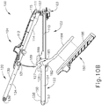
- FIGS. 30A-30B show an alternative firing assembly (570) that may be readily incorporated into instrument (400) described above.
- Firing assembly (570) includes a proximal body (573), an actuating beam (572), a staple sled assembly (571), a first firing lever (580), a second firing lever (586), and a linkage arm (590) coupled to each firing lever (580, 586) via connecting ends (594, 592).
- Proximal body (573) includes pivots posts (574, 575) which are pivotably coupled with couplings sleeves (588, 582) of firings levers (586, 582).
- levers (586, 582) drives proximal body (573), actuating beam (572), and staple sled assembly (571). Additionally, both levers (580, 586) actuate with actuating beam (572) and staple sled assembly (571) during exemplary use.
- first lever (580) and second lever (586) are pivotably coupled with posts (574, 575) such that when one lever (580, 586) is pivoted to a laterally extended position, the other lever (580, 586) is pivoted inward into a non-obtrusive position such that during a firing stroke in accordance with the description above, the inward pivoted lever (580, 586) does not interfere with an operator grasping instrument (400).
- levers (580, 586) when one lever (580, 586) is pivoted to the laterally extended outward position, linkage arm (590) rotates the other lever (580, 586) to a non-obtrusive position.
- Each lever (580, 586) has a contoured contact body (584, 858) dimensioned to abut against each other when levers (580, 586) pivot to relative to each other between the positions shown in FIGS. 30A-30B .
- FIGS. 31A-31C show an alternative firing assembly (600) that may be readily incorporated into instrument (400) described above.
- Firing assembly (600) includes a proximal compliant lever retaining body (603), an actuating beam (602), a staple sled assembly (601), and a firing lever (612).
- Actuating beam (602) and staple sled assembly (601) are substantially similar to actuating beam (502) and staple sled assembly (501) described above.
- firing lever (510) is configured to slide laterally within proximal compliant lever retaining body (603) such that firing lever (510) may be accessible from either side (416, 417) of instrument (400).
- Proximal body (603) defines a transverse channel (606) having a first side compliant chamber, a middle compliant chamber (609) and a second side compliant chamber (610). Proximal body (603) is made from a resilient material. Each compliant chamber (608,609, 610) is configured to house a middle protrusion (618) of firing lever (612).
- Firing lever (612) includes a first lateral side (614), a second lateral side (616), and middle protrusion. As best seen between FIGS. 31A-31C , firing lever (612) may slide within transverse channel (606) from a middle position ( FIGS. 31A ), a first lateral position ( FIG. 31B ), and a second lateral position ( FIG. 31C ). As will be discussed in greater detail below, an operator may push and/or pull lever (612) between each position in order to access first lateral side (614) or second lateral side (616) for actuating firing assembly (600).
- middle protrusion (618) While in the middle position, middle protrusion (618) may be located within middle compliant chamber (609).
- the interior surfaces of proximal body (603) defining middle compliant chamber (609) are configured to engage middle protrusion (618) such that lever (612) remains stationary relative to proximal body (603).
- first lateral side (614) or second lateral side (616) may be partially within transverse channel (606).
- proximal body (603) is sufficiently compliant and resilient such that if an operator desires, they may slide firing lever (612) to either lateral side of proximal body (603) such that middle protrusion (618) slides within either first side compliant chamber (608) of second side compliant chamber (610).
- the interior or proximal body (603) defining transverse channel (606) may expand such that middle protrusion (618) may slide within chamber (608, 609, 610).
- middle production (618) is within either chamber (608, 609, 610) and an operator stops pushing/pulling lever (612)
- the compliant and/or resilient nature or proximal body (603) will reengage middle protrusion (614) of lever (612). Therefore, an operator may push/pull lever (612) laterally such that either first lateral side (614) or second lateral side (616) is exposed for grasping and firing actuating beam (602) and staple sled assembly (601).
- FIGS. 32-33 show another firing assembly (620) that may be readily incorporated into instrument (400).
- Firing assembly (600) includes a proximal body (623) defining a cam slot (624), an actuating beam (622) coupled to proximal body (623), a staple sled assembly (621) coupled with actuating beam (622), and a firing lever (630).
- Actuating beam (622) and staple sled assembly (621) may be substantially similar to actuating beam (502) and staple sled assembly (501) described above.
- a portion of firing lever (630) is slidable coupled within the confines of cam slot (624) such that when firing lever (630) is pushed or pulled laterally, firing lever (330) rotates.
- Firing lever (630) includes a first firing arm (632), a second firing arm (634), a torsional portion (636) located between first firing arm (632) and second firing arm (634), and lateral protrusions (635) located along portions of first firing arm (632) and second firing arm (634) adjacent to torsional portion (636).
- Torsional portion (636) is within the confines of cam slot (624) such that an operator may push or pull firing lever (630) such that torsional portion (636) and cam slot (624) interact with each other in order to rotate firing lever (630) relative to proximal body (623). In particular, when firing lever (630) is in the position shown in FIG.
- second firing arm (634) may be grasped for actuating firing assembly (620).
- first firing arm (632) may be grasped for actuating firing assembly (620). Therefore, an operator may push/pull on firing lever (630) toward the side in which an operator wishes to grasp firing lever (630).
- Lateral protrusion (635) are dimensioned to prevent firing lever (630) from disassociating with proximal body (623).
- An apparatus comprising: (a) a handle assembly, wherein the handle assembly comprises: (i) a first lateral side, (ii) a second lateral side, (iii) a first arm, (iv) a second arm, wherein the second arm is configured to pivotably couple with the first arm at a proximal pivot location, and (v) a latching lever pivotably coupled with the first arm at a distal pivot location; (b) an end effector, wherein the end effector comprises: (i) a first jaw extending distally from the first arm, and (ii) a second jaw extending distally from the second arm, wherein the second jaw is configured to pivot relative to the first jaw between an open configuration, a partially closed configuration, and a fully closed configuration, wherein the latching lever is configured engage the second arm or the second jaw to pivot the second jaw from the partially closed configuration toward the fully closed configuration; and (c) a firing assembly configured to sever tissue captured between the first jaw and the second jaw in the fully closed
- Example 1 The apparatus of Example 1, wherein the proximal body comprises a first post and a second post.
- Example 2 wherein the first lever comprises pivoting connector and a grasping connector, wherein the pivoting connector is configured to pivotably couple the first lever with the first post while the proximal body is in a proximal position.
- Example 3 wherein the grasping connector is configured to couple with the second post in the first laterally extending position, wherein the grasping connector is configured to decouple with the second post in the first non-obtrusive position.
- Example 4 The apparatus of Example 4, wherein the first lever is configured to drive the actuating beam independently of the second lever.
- the first arm defines an upper slot on the first lateral side and a lower slot on the second lateral side, wherein the grasping connector is first configured to pass through the upper slot of the first lateral side when moving between the first lateral position and the first non-obtrusive position.
- proximal body defines a rotational locking pocket configured to receive a portion of the first lever in the first lateral position.
- Example 9 The apparatus of Example 9, wherein the proximal body defines a transverse channel, wherein the first lever and the second lever are connected with each other by a linkage arm.
- proximal body defines a transverse channel, wherein the first lever and the second lever are connected to each other by a sliding coupling arm.
- Example 11 wherein the first lever defines a first cam slot, wherein the first lever is coupled with the sliding coupling arm via a first pin and the first cam slot.
- Example 12 wherein the second lever defines a second cam slot, wherein the second lever is coupled with the sliding coupling arm via a second pin and the second cam slot.
- first handle defines a firing channel housing the actuating beam, wherein the first handle further defines a first lever channel configured to receive the first lever in the first non-obtrusive position.
- Example 15 wherein the first handle further defines a second lever channel configured to receive the second lever in the second non-obtrusive position.
- An apparatus comprising: (a) a handle assembly, wherein the handle assembly comprises: (i) a first lateral side, (ii) a second lateral side, (iii) a first arm, (iv) a second arm, wherein the second arm is configured to pivotably couple with the first arm at a proximal pivot location, and (v) a latching lever pivotably coupled with the first arm at a distal pivot location; (b) an end effector, wherein the end effector comprises: (i) a first jaw extending distally from the first arm, and (ii) a second jaw extending distally from the second arm, wherein the second jaw is configured to pivot relative to the first jaw between an open configuration, a partially closed configuration, and a fully closed configuration, wherein the latching lever is configured engage the second arm or the second jaw to pivot the second jaw from the partially closed configuration toward the fully closed configuration; and (c) a firing assembly configured to sever tissue captured between the first jaw and the second jaw in the fully closed
- Example 17 wherein the first arm defines an upper slot associated with the first lateral side, wherein the first arm defines a lower slot associated with the second lateral side, wherein the first lever is slidably coupled with the upper slot, wherein the second lever is slidably coupled with the lower slot.
- Example 18 wherein the upper slot further defines a pivot lock window configured to receive a rotational lock body of the first lever in the first laterally extending position.
- An apparatus comprising: (a) a handle assembly, wherein the handle assembly comprises: (i) a first lateral side, (ii) a second lateral side, (iii) a first arm, (iv) a second arm, wherein the second arm is configured to pivotably couple with the first arm at a proximal pivot location, and (v) a latching lever pivotably coupled with the first arm at a distal pivot location; (b) an end effector, wherein the end effector comprises: (i) a first jaw extending distally from the first arm, and (ii) a second jaw extending distally from the second arm, wherein the second jaw is configured to pivot relative to the first jaw between an open configuration, a partially closed configuration, and a fully closed configuration, wherein the latching lever is configured engage the second arm or the second jaw to pivot the second jaw from the partially closed configuration toward the fully closed configuration; and (c) a firing assembly configured to sever tissue captured between the first jaw and the second jaw in the fully closed
- any one or more of the teachings, expressions, embodiments, examples, etc. described herein may be combined with any one or more of the teachings, expressions, embodiments, examples, etc. described in U.S. App. No. [Atty. Ref. END7969USNP], entitled “Release Mechanism for Linear Surgical Stapler,” filed on even date herewith; U.S. App. No. [Atty. Ref. END7970USNP], entitled “Lockout Assembly for Linear Surgical Stapler,” filed on even date herewith; U.S. App. No. [Atty. Ref.
- Versions of the devices described above may have application in conventional medical treatments and procedures conducted by a medical professional, as well as application in robotic-assisted medical treatments and procedures.
- various teachings herein may be readily incorporated into a robotic surgical system such as the DAVINCITM system by Intuitive Surgical, Inc., of Sunnyvale, California.
- Versions described above may be designed to be disposed of after a single use, or they can be designed to be used multiple times. Versions may, in either or both cases, be reconditioned for reuse after at least one use. Reconditioning may include any combination of the steps of disassembly of the device, followed by cleaning or replacement of particular pieces, and subsequent reassembly. In particular, some versions of the device may be disassembled, and any number of the particular pieces or parts of the device may be selectively replaced or removed in any combination. Upon cleaning and/or replacement of particular parts, some versions of the device may be reassembled for subsequent use either at a reconditioning facility, or by a operator immediately prior to a procedure.
- reconditioning of a device may utilize a variety of techniques for disassembly, cleaning/replacement, and reassembly. Use of such techniques, and the resulting reconditioned device, are all within the scope of the present application.
- versions described herein may be sterilized before and/or after a procedure.
- the device is placed in a closed and sealed container, such as a plastic or TYVEK bag.
- the container and device may then be placed in a field of radiation that can penetrate the container, such as gamma radiation, x-rays, or high-energy electrons.
- the radiation may kill bacteria on the device and in the container.
- the sterilized device may then be stored in the sterile container for later use.
- a device may also be sterilized using any other technique known in the art, including but not limited to beta or gamma radiation, ethylene oxide, or steam.
Landscapes
- Health & Medical Sciences (AREA)
- Life Sciences & Earth Sciences (AREA)
- Surgery (AREA)
- Heart & Thoracic Surgery (AREA)
- Engineering & Computer Science (AREA)
- Biomedical Technology (AREA)
- Nuclear Medicine, Radiotherapy & Molecular Imaging (AREA)
- Medical Informatics (AREA)
- Molecular Biology (AREA)
- Animal Behavior & Ethology (AREA)
- General Health & Medical Sciences (AREA)
- Public Health (AREA)
- Veterinary Medicine (AREA)
- Physiology (AREA)
- Surgical Instruments (AREA)
Applications Claiming Priority (1)
| Application Number | Priority Date | Filing Date | Title |
|---|---|---|---|
| US15/889,388 US10874398B2 (en) | 2018-02-06 | 2018-02-06 | Firing lever assembly for linear surgical stapler |
Publications (2)
| Publication Number | Publication Date |
|---|---|
| EP3520625A1 true EP3520625A1 (fr) | 2019-08-07 |
| EP3520625B1 EP3520625B1 (fr) | 2022-01-05 |
Family
ID=65324208
Family Applications (1)
| Application Number | Title | Priority Date | Filing Date |
|---|---|---|---|
| EP19155449.2A Active EP3520625B1 (fr) | 2018-02-06 | 2019-02-05 | Ensemble de levier de déclenchement pour agrafeuse chirurgicale linéaire |
Country Status (7)
| Country | Link |
|---|---|
| US (1) | US10874398B2 (fr) |
| EP (1) | EP3520625B1 (fr) |
| JP (1) | JP7395507B2 (fr) |
| CN (1) | CN111936062A (fr) |
| BR (1) | BR112020015980A2 (fr) |
| MX (1) | MX2020008288A (fr) |
| WO (1) | WO2019155304A1 (fr) |
Families Citing this family (12)
| Publication number | Priority date | Publication date | Assignee | Title |
|---|---|---|---|---|
| US10631866B2 (en) | 2018-02-06 | 2020-04-28 | Ethicon Llc | Release mechanism for linear surgical stapler |
| US10898187B2 (en) | 2018-08-13 | 2021-01-26 | Ethicon Llc | Firing system for linear surgical stapler |
| US10905419B2 (en) | 2018-10-11 | 2021-02-02 | Ethicon Llc | Closure assembly for linear surgical stapler |
| US11464508B2 (en) | 2019-05-13 | 2022-10-11 | Cilag Gmbh International | Actuator retainer for surgical stapler |
| US11166715B2 (en) | 2019-05-13 | 2021-11-09 | Cilag Gmbh International | Actuator support structure for surgical stapler |
| US11229433B2 (en) | 2019-08-09 | 2022-01-25 | Cilag Gmbh International | Linear surgical stapler |
| USD955575S1 (en) | 2019-08-09 | 2022-06-21 | Cilag Gmbh International | Staple cartridge assembly for linear surgical stapler |
| USD956230S1 (en) | 2019-08-09 | 2022-06-28 | Cilag Gmbh International | Staple cartridge assembly for linear surgical stapler |
| US11224425B2 (en) | 2020-05-29 | 2022-01-18 | Cilag Gmbh International | Surgical linear cutter wishbone separation mechanism with detent |
| US11219454B2 (en) | 2020-05-29 | 2022-01-11 | Cilag Gmbh International | Pin trap mechanism for surgical linear cutter |
| US11937812B2 (en) | 2021-09-30 | 2024-03-26 | Cilag Gmbh International | Lockout feature for linear surgical stapler cartridge |
| WO2023242702A1 (fr) | 2022-06-14 | 2023-12-21 | Cilag Gmbh International | Agrafeuse chirurgicale linéaire |
Citations (8)
| Publication number | Priority date | Publication date | Assignee | Title |
|---|---|---|---|---|
| US20050222616A1 (en) * | 2001-10-05 | 2005-10-06 | Rethy Csaba L | Surgical fastener applying apparatus |
| US7905381B2 (en) | 2008-09-19 | 2011-03-15 | Ethicon Endo-Surgery, Inc. | Surgical stapling instrument with cutting member arrangement |
| US20110084113A1 (en) * | 2009-10-09 | 2011-04-14 | Ethicon Endo-Surgery, Inc. | Surgical stapler comprising a staple pocket |
| CN103190938A (zh) * | 2012-01-05 | 2013-07-10 | 常州市康迪医用吻合器有限公司 | 外科线形切割吻合器的钉仓组件 |
| EP2700366A1 (fr) * | 2011-04-20 | 2014-02-26 | Touchstone International Medical Science Co., Ltd. | Dispositif de couture et coupe rectiligne |
| CN103845093A (zh) * | 2012-12-04 | 2014-06-11 | 常州市康迪医用吻合器有限公司 | 外科线形切割吻合器的击发机构 |
| US8789740B2 (en) | 2010-07-30 | 2014-07-29 | Ethicon Endo-Surgery, Inc. | Linear cutting and stapling device with selectively disengageable cutting member |
| WO2015065487A1 (fr) * | 2013-11-04 | 2015-05-07 | Covidien Lp | Appareil d'application d'agrafes chirurgicales |
Family Cites Families (135)
| Publication number | Priority date | Publication date | Assignee | Title |
|---|---|---|---|---|
| US960300A (en) | 1908-07-16 | 1910-06-07 | Victor Fischer | Wire-stitching instrument. |
| US3078465A (en) | 1959-09-09 | 1963-02-26 | Bobrov Boris Sergueevitch | Instrument for stitching gastric stump |
| GB927936A (en) | 1959-10-02 | 1963-06-06 | Boris Sergeevich Bobrov | An instrument for making anastomoses |
| US3079606A (en) | 1960-01-04 | 1963-03-05 | Bobrov Boris Sergeevich | Instrument for placing lateral gastrointestinal anastomoses |
| US3317105A (en) | 1964-03-25 | 1967-05-02 | Niiex Khirurgicheskoi Apparatu | Instrument for placing lateral intestinal anastomoses |
| US3315863A (en) | 1965-07-06 | 1967-04-25 | United States Surgical Corp | Medical instrument |
| US3490675A (en) | 1966-10-10 | 1970-01-20 | United States Surgical Corp | Instrument for placing lateral gastrointestinal anastomoses |
| SU566574A1 (ru) | 1975-05-04 | 1977-07-30 | Всесоюзный научно-исследовательский и испытательный институт медицинской техники | Аппарат дл наложени линейного скобочного шва на органы и ткани |
| SU599799A1 (ru) | 1975-12-26 | 1978-04-05 | Всесоюзный научно-исследовательский и испытательный институт медицинской техники | Хирургический сшивающий аппарат |
| US4241861A (en) | 1977-12-20 | 1980-12-30 | Fleischer Harry N | Scissor-type surgical stapler |
| SU886897A1 (ru) | 1978-12-25 | 1981-12-07 | Всесоюзный Научно-Исследовательский Институт Медицинской Техники | Хирургический аппарат дл наложени боковых желудочнокишечных анастомозов |
| US4429695A (en) | 1980-02-05 | 1984-02-07 | United States Surgical Corporation | Surgical instruments |
| AU534210B2 (en) | 1980-02-05 | 1984-01-12 | United States Surgical Corporation | Surgical staples |
| USD272852S (en) | 1980-12-19 | 1984-02-28 | United States Surgical Corporation | Linear anastomosis stapler |
| USD272851S (en) | 1981-01-09 | 1984-02-28 | United States Surgical Corporation | Linear anastomosis stapler |
| SU1183082A1 (ru) | 1983-08-19 | 1985-10-07 | Всесоюзный научно-исследовательский и испытательный институт медицинской техники | Хирургический сшивающий аппарат |
| US4610383A (en) | 1983-10-14 | 1986-09-09 | Senmed, Inc. | Disposable linear surgical stapler |
| US4633861A (en) | 1984-10-19 | 1987-01-06 | Senmed, Inc. | Surgical stapling instrument with jaw clamping mechanism |
| US4633874A (en) | 1984-10-19 | 1987-01-06 | Senmed, Inc. | Surgical stapling instrument with jaw latching mechanism and disposable staple cartridge |
| US4608981A (en) | 1984-10-19 | 1986-09-02 | Senmed, Inc. | Surgical stapling instrument with staple height adjusting mechanism |
| US4605001A (en) | 1984-10-19 | 1986-08-12 | Senmed, Inc. | Surgical stapling instrument with dual staple height mechanism |
| USD285836S (en) | 1985-01-07 | 1986-09-23 | Senmed, Inc. | Surgical stapler |
| US4869415A (en) | 1988-09-26 | 1989-09-26 | Ethicon, Inc. | Energy storage means for a surgical stapler |
| JPH02121645A (ja) | 1988-10-31 | 1990-05-09 | Matsutani Seisakusho Co Ltd | 医療用ステープルとその製造方法 |
| US4892244A (en) | 1988-11-07 | 1990-01-09 | Ethicon, Inc. | Surgical stapler cartridge lockout device |
| US5505363A (en) | 1989-05-26 | 1996-04-09 | United States Surgical Corporation | Surgical staples with plated anvils |
| US4955959A (en) | 1989-05-26 | 1990-09-11 | United States Surgical Corporation | Locking mechanism for a surgical fastening apparatus |
| US5653373A (en) | 1990-09-17 | 1997-08-05 | United States Surgical Corporation | Arcuate apparatus for applying two-part surgical fasteners |
| US5156614A (en) | 1990-09-17 | 1992-10-20 | United States Surgical Corporation | Apparatus for applying two-part surgical fasteners |
| US5129570A (en) | 1990-11-30 | 1992-07-14 | Ethicon, Inc. | Surgical stapler |
| BR9107241A (pt) | 1990-12-18 | 1994-02-16 | Minnesota Mining & Mfg | Conjunto de cartucho para grampos adaptado para uso em um grampeador cirurgico |
| US5141144A (en) | 1990-12-18 | 1992-08-25 | Minnesota Mining And Manufacturing Company | Stapler and firing device |
| US5083695A (en) | 1990-12-18 | 1992-01-28 | Minnesota Mining And Manufacturing Company | Stapler and firing device |
| US5065929A (en) | 1991-04-01 | 1991-11-19 | Ethicon, Inc. | Surgical stapler with locking means |
| US5221036A (en) | 1991-06-11 | 1993-06-22 | Haruo Takase | Surgical stapler |
| US5173133A (en) | 1991-07-23 | 1992-12-22 | United States Surgical Corporation | Method for annealing stapler anvils |
| US5395034A (en) | 1991-11-07 | 1995-03-07 | American Cyanamid Co. | Linear surgical stapling instrument |
| US5415334A (en) | 1993-05-05 | 1995-05-16 | Ethicon Endo-Surgery | Surgical stapler and staple cartridge |
| US5364003A (en) | 1993-05-05 | 1994-11-15 | Ethicon Endo-Surgery | Staple cartridge for a surgical stapler |
| US5542594A (en) | 1993-10-06 | 1996-08-06 | United States Surgical Corporation | Surgical stapling apparatus with biocompatible surgical fabric |
| US5452837A (en) | 1994-01-21 | 1995-09-26 | Ethicon Endo-Surgery, Inc. | Surgical stapler with tissue gripping ridge |
| US5465895A (en) | 1994-02-03 | 1995-11-14 | Ethicon Endo-Surgery, Inc. | Surgical stapler instrument |
| JPH0833642A (ja) | 1994-02-25 | 1996-02-06 | Ethicon Endo Surgery Inc | 外科用ステープラのための改良アンビル承口 |
| US5489058A (en) | 1994-05-02 | 1996-02-06 | Minnesota Mining And Manufacturing Company | Surgical stapler with mechanisms for reducing the firing force |
| US5551622A (en) | 1994-07-13 | 1996-09-03 | Yoon; Inbae | Surgical stapler |
| US5507426A (en) | 1994-08-05 | 1996-04-16 | United States Surgical Corporation | Apparatus for applying surgical fasteners |
| US5988479A (en) | 1994-12-13 | 1999-11-23 | United States Surgical Corporation | Apparatus for applying surgical fasteners |
| US5636779A (en) | 1994-12-13 | 1997-06-10 | United States Surgical Corporation | Apparatus for applying surgical fasteners |
| US5718359A (en) | 1995-08-14 | 1998-02-17 | United States Of America Surgical Corporation | Surgical stapler with lockout mechanism |
| CA2188738A1 (fr) | 1995-10-27 | 1997-04-28 | Lisa W. Heaton | Agrafeuse chirurgicale possedant des unites de chargement interchangeables |
| US5651491A (en) | 1995-10-27 | 1997-07-29 | United States Surgical Corporation | Surgical stapler having interchangeable loading units |
| US5673842A (en) | 1996-03-05 | 1997-10-07 | Ethicon Endo-Surgery | Surgical stapler with locking mechanism |
| US5785232A (en) | 1996-04-17 | 1998-07-28 | Vir Engineering | Surgical stapler |
| US5752965A (en) | 1996-10-21 | 1998-05-19 | Bio-Vascular, Inc. | Apparatus and method for producing a reinforced surgical fastener suture line |
| US6099551A (en) | 1998-03-12 | 2000-08-08 | Shelhigh, Inc. | Pericardial strip and stapler assembly for dividing and sealing visceral tissues and method of use thereof |
| US6206903B1 (en) | 1999-10-08 | 2001-03-27 | Intuitive Surgical, Inc. | Surgical tool with mechanical advantage |
| DE60135920D1 (de) | 2000-10-13 | 2008-11-06 | Tyco Healthcare | Chirurgisches instrument zum anlegen von klammern |
| US7032799B2 (en) | 2001-10-05 | 2006-04-25 | Tyco Healthcare Group Lp | Surgical stapling apparatus and method |
| WO2003079909A2 (fr) | 2002-03-19 | 2003-10-02 | Tyco Healthcare Group, Lp | Appareil d'application d'element d'attache chirurgical |
| US20040267310A1 (en) | 2000-10-20 | 2004-12-30 | Racenet David C | Directionally biased staple and anvil assembly for forming the staple |
| AU2003226050A1 (en) | 2002-04-11 | 2003-10-27 | Tyco Healthcare Group, Lp | Surgical stapling apparatus including an anvil and cartridge each having cooperating mating surfaces |
| US7238195B2 (en) | 2002-05-10 | 2007-07-03 | Tyco Healthcare Group Lp | Wound closure material applicator and stapler |
| ES2503550T3 (es) | 2002-05-10 | 2014-10-07 | Covidien Lp | Aparato grapador quirúrgico que tiene un conjunto aplicador de material para cierre de heridas |
| DE60307820T2 (de) | 2002-05-10 | 2007-03-29 | Tyco Healthcare Group Lp, Norwalk | Elektrochirurgisches klammergerät |
| WO2003094747A1 (fr) | 2002-05-13 | 2003-11-20 | Tyco Healthcare Group, Lp | Agrafeuse chirurgicale et unite de chargement jetable presentant des agrafes de differentes tailles |
| EP1507572B1 (fr) | 2002-05-17 | 2007-01-10 | Tyco Healthcare Group Lp | Applicateur de matière de fermeture de plaie |
| AU2003282721B2 (en) | 2002-10-04 | 2008-10-23 | Covidien Lp | Surgical stapler with universal articulation and tissue pre-clamp |
| US7296722B2 (en) | 2003-10-17 | 2007-11-20 | Tyco Healthcare Group Lp | Surgical fastener applying apparatus with controlled beam deflection |
| US7210609B2 (en) | 2004-07-30 | 2007-05-01 | Tools For Surgery, Llc | Stapling apparatus having a curved anvil and driver |
| US7121446B2 (en) | 2004-12-13 | 2006-10-17 | Niti Medical Technologies Ltd. | Palm-size surgical stapler for single hand operation |
| US20060180633A1 (en) | 2005-02-17 | 2006-08-17 | Tyco Healthcare Group, Lp | Surgical staple |
| US7288098B2 (en) | 2005-04-14 | 2007-10-30 | Ethicon Endo-Surgery, Inc. | Force limiting mechanism for medical instrument |
| US7722610B2 (en) | 2005-06-02 | 2010-05-25 | Tyco Healthcare Group Lp | Multiple coil staple and staple applier |
| US7717312B2 (en) | 2005-06-03 | 2010-05-18 | Tyco Healthcare Group Lp | Surgical instruments employing sensors |
| US8573462B2 (en) | 2006-05-19 | 2013-11-05 | Ethicon Endo-Surgery, Inc. | Electrical surgical instrument with optimized power supply and drive |
| US8679154B2 (en) | 2007-01-12 | 2014-03-25 | Ethicon Endo-Surgery, Inc. | Adjustable compression staple and method for stapling with adjustable compression |
| EP1917125B1 (fr) | 2005-07-27 | 2011-09-07 | Tyco Healthcare Group LP | Agencement de poches d'agrafes pour agrafeuse chirurgicale |
| US7401721B2 (en) | 2005-08-15 | 2008-07-22 | Tyco Healthcare Group Lp | Surgical stapling instruments including a cartridge having multiple staple sizes |
| US8579178B2 (en) | 2005-08-15 | 2013-11-12 | Covidien Lp | Surgical stapling instruments including a cartridge having multiple staples sizes |
| US7398908B2 (en) | 2005-08-15 | 2008-07-15 | Tyco Healthcare Group Lp | Surgical stapling instruments including a cartridge having multiple staple sizes |
| US7407075B2 (en) | 2005-08-15 | 2008-08-05 | Tyco Healthcare Group Lp | Staple cartridge having multiple staple sizes for a surgical stapling instrument |
| US7407078B2 (en) | 2005-09-21 | 2008-08-05 | Ehthicon Endo-Surgery, Inc. | Surgical stapling instrument having force controlled spacing end effector |
| US7467740B2 (en) | 2005-09-21 | 2008-12-23 | Ethicon Endo-Surgery, Inc. | Surgical stapling instruments having flexible channel and anvil features for adjustable staple heights |
| US7641091B2 (en) | 2005-10-04 | 2010-01-05 | Tyco Healthcare Group Lp | Staple drive assembly |
| US7635074B2 (en) | 2005-10-04 | 2009-12-22 | Tyco Healthcare Group Lp | Staple drive assembly |
| US20110290856A1 (en) | 2006-01-31 | 2011-12-01 | Ethicon Endo-Surgery, Inc. | Robotically-controlled surgical instrument with force-feedback capabilities |
| US7422139B2 (en) | 2006-01-31 | 2008-09-09 | Ethicon Endo-Surgery, Inc. | Motor-driven surgical cutting fastening instrument with tactile position feedback |
| US7845537B2 (en) | 2006-01-31 | 2010-12-07 | Ethicon Endo-Surgery, Inc. | Surgical instrument having recording capabilities |
| WO2007112059A2 (fr) | 2006-03-23 | 2007-10-04 | Edrich Health Technologies , Inc. | Agrafeuses anastomotiques vasculaires |
| US7278563B1 (en) | 2006-04-25 | 2007-10-09 | Green David T | Surgical instrument for progressively stapling and incising tissue |
| EP2018248B1 (fr) * | 2006-05-19 | 2015-11-04 | Applied Medical Resources Corporation | Agrafeuse chirurgicale |
| US8409244B2 (en) | 2007-04-16 | 2013-04-02 | Intuitive Surgical Operations, Inc. | Tool with end effector force limiter |
| US8720766B2 (en) | 2006-09-29 | 2014-05-13 | Ethicon Endo-Surgery, Inc. | Surgical stapling instruments and staples |
| US20100133317A1 (en) | 2006-09-29 | 2010-06-03 | Shelton Iv Frederick E | Motor-Driven Surgical Cutting And Fastening Instrument with Tactile Position Feedback |
| US8708210B2 (en) | 2006-10-05 | 2014-04-29 | Covidien Lp | Method and force-limiting handle mechanism for a surgical instrument |
| US7637410B2 (en) | 2006-10-06 | 2009-12-29 | Tyco Healthcare Group Lp | Surgical instrument including a locking assembly |
| WO2008057281A2 (fr) | 2006-10-26 | 2008-05-15 | Tyco Healthcare Group Lp | Procédés d'utilisation d'alliages à mémoire de forme pour une fixation de renfort |
| US7490749B2 (en) | 2007-03-28 | 2009-02-17 | Ethicon Endo-Surgery, Inc. | Surgical stapling and cutting instrument with manually retractable firing member |
| US7810691B2 (en) | 2007-05-16 | 2010-10-12 | The Invention Science Fund I, Llc | Gentle touch surgical stapler |
| US7832611B2 (en) | 2007-05-16 | 2010-11-16 | The Invention Science Fund I, Llc | Steerable surgical stapler |
| US8062330B2 (en) | 2007-06-27 | 2011-11-22 | Tyco Healthcare Group Lp | Buttress and surgical stapling apparatus |
| US8636939B2 (en) | 2007-11-06 | 2014-01-28 | Covidien Lp | Mold for actuation sled |
| US7954685B2 (en) | 2007-11-06 | 2011-06-07 | Tyco Healthcare Group Lp | Articulation and firing force mechanisms |
| US8727199B2 (en) | 2008-01-03 | 2014-05-20 | Covidien Lp | Surgical stapler |
| US7766209B2 (en) | 2008-02-13 | 2010-08-03 | Ethicon Endo-Surgery, Inc. | Surgical stapling instrument with improved firing trigger arrangement |
| US8231040B2 (en) | 2008-04-14 | 2012-07-31 | Tyco Healthcare Group Lp | Variable compression surgical fastener cartridge |
| US20090255974A1 (en) | 2008-04-14 | 2009-10-15 | Tyco Healthcare Group Lp | Single loop surgical fastener apparatus for applying variable compression |
| US8028884B2 (en) | 2008-04-22 | 2011-10-04 | Tyco Healthcare Group Lp | Cartridge for applying varying amounts of tissue compression |
| US9016541B2 (en) | 2008-05-09 | 2015-04-28 | Covidien Lp | Varying tissue compression with an anvil configuration |
| US8464922B2 (en) | 2008-05-09 | 2013-06-18 | Covidien Lp | Variable compression surgical fastener cartridge |
| US20090308907A1 (en) * | 2008-06-12 | 2009-12-17 | Nalagatla Anil K | Partially reusable surgical stapler |
| US8308043B2 (en) * | 2009-05-19 | 2012-11-13 | Covidien Lp | Recognition of interchangeable component of a device |
| US8257634B2 (en) | 2009-10-06 | 2012-09-04 | Tyco Healthcare Group Lp | Actuation sled having a curved guide member and method |
| US8496154B2 (en) | 2009-10-08 | 2013-07-30 | Covidien Lp | Pair of double staple pusher in triple row stapler |
| US8152041B2 (en) | 2009-10-14 | 2012-04-10 | Tyco Healthcare Group Lp | Varying tissue compression aided by elastic members |
| US8418907B2 (en) | 2009-11-05 | 2013-04-16 | Covidien Lp | Surgical stapler having cartridge with adjustable cam mechanism |
| US8267300B2 (en) | 2009-12-30 | 2012-09-18 | Ethicon Endo-Surgery, Inc. | Dampening device for endoscopic surgical stapler |
| US9750502B2 (en) | 2010-10-01 | 2017-09-05 | Covidien Lp | Surgical stapling device for performing circular anastomosis and surgical staples for use therewith |
| US9289209B2 (en) | 2011-06-09 | 2016-03-22 | Covidien Lp | Surgical fastener applying apparatus |
| US9451959B2 (en) | 2011-06-09 | 2016-09-27 | Covidien Lp | Surgical fastener applying apparatus |
| US9271728B2 (en) * | 2011-06-09 | 2016-03-01 | Covidien Lp | Surgical fastener applying apparatus |
| WO2012171423A1 (fr) | 2011-06-14 | 2012-12-20 | 常州市康迪医用吻合器有限公司 | Clou chirurgical pour agrafeuse en forme de rein et sillon de mise en forme associé |
| WO2013016126A1 (fr) | 2011-07-22 | 2013-01-31 | The General Hospital Corporation | Nanoparticules thérapeutiques et procédés d'utilisation de celles-ci |
| US9724095B2 (en) * | 2011-08-08 | 2017-08-08 | Covidien Lp | Surgical fastener applying apparatus |
| US9155537B2 (en) | 2011-08-08 | 2015-10-13 | Covidien Lp | Surgical fastener applying apparatus |
| US9539007B2 (en) * | 2011-08-08 | 2017-01-10 | Covidien Lp | Surgical fastener applying aparatus |
| CN104066388B (zh) | 2012-01-18 | 2017-05-31 | 柯惠Lp公司 | 手术紧固件施加设备 |
| US10299815B2 (en) | 2012-01-19 | 2019-05-28 | Covidien Lp | Surgical instrument with clam releases mechanism |
| US9119617B2 (en) | 2012-03-16 | 2015-09-01 | Ethicon, Inc. | Clamping devices for dispensing surgical fasteners into soft media |
| CN103800041B (zh) * | 2012-11-01 | 2016-02-10 | 苏州天臣国际医疗科技有限公司 | 医用钉合切割器械 |
| US9566062B2 (en) * | 2012-12-03 | 2017-02-14 | Ethicon Endo-Surgery, Llc | Surgical instrument with secondary jaw closure feature |
| US11033264B2 (en) | 2013-11-04 | 2021-06-15 | Covidien Lp | Surgical fastener applying apparatus |
| CA2926751A1 (fr) | 2013-11-04 | 2015-05-07 | Covidien Lp | Appareil d'application d'agrafes chirurgicales |
| US11083491B2 (en) | 2014-12-09 | 2021-08-10 | Medtronic, Inc. | Extravascular implant tools utilizing a bore-in mechanism and implant techniques using such tools |
| US20200029966A1 (en) * | 2017-03-09 | 2020-01-30 | Covidien Lp | Surgical Stapling Device With Variable Height Staple Pushers |
-
2018
- 2018-02-06 US US15/889,388 patent/US10874398B2/en active Active
-
2019
- 2019-01-16 BR BR112020015980-8A patent/BR112020015980A2/pt unknown
- 2019-01-16 JP JP2020563833A patent/JP7395507B2/ja active Active
- 2019-01-16 WO PCT/IB2019/050360 patent/WO2019155304A1/fr active Application Filing
- 2019-01-16 CN CN201980022824.XA patent/CN111936062A/zh active Pending
- 2019-01-16 MX MX2020008288A patent/MX2020008288A/es unknown
- 2019-02-05 EP EP19155449.2A patent/EP3520625B1/fr active Active
Patent Citations (10)
| Publication number | Priority date | Publication date | Assignee | Title |
|---|---|---|---|---|
| US20050222616A1 (en) * | 2001-10-05 | 2005-10-06 | Rethy Csaba L | Surgical fastener applying apparatus |
| US7905381B2 (en) | 2008-09-19 | 2011-03-15 | Ethicon Endo-Surgery, Inc. | Surgical stapling instrument with cutting member arrangement |
| US7954686B2 (en) | 2008-09-19 | 2011-06-07 | Ethicon Endo-Surgery, Inc. | Surgical stapler with apparatus for adjusting staple height |
| US20110084113A1 (en) * | 2009-10-09 | 2011-04-14 | Ethicon Endo-Surgery, Inc. | Surgical stapler comprising a staple pocket |
| US8348129B2 (en) | 2009-10-09 | 2013-01-08 | Ethicon Endo-Surgery, Inc. | Surgical stapler having a closure mechanism |
| US8789740B2 (en) | 2010-07-30 | 2014-07-29 | Ethicon Endo-Surgery, Inc. | Linear cutting and stapling device with selectively disengageable cutting member |
| EP2700366A1 (fr) * | 2011-04-20 | 2014-02-26 | Touchstone International Medical Science Co., Ltd. | Dispositif de couture et coupe rectiligne |
| CN103190938A (zh) * | 2012-01-05 | 2013-07-10 | 常州市康迪医用吻合器有限公司 | 外科线形切割吻合器的钉仓组件 |
| CN103845093A (zh) * | 2012-12-04 | 2014-06-11 | 常州市康迪医用吻合器有限公司 | 外科线形切割吻合器的击发机构 |
| WO2015065487A1 (fr) * | 2013-11-04 | 2015-05-07 | Covidien Lp | Appareil d'application d'agrafes chirurgicales |
Also Published As
| Publication number | Publication date |
|---|---|
| EP3520625B1 (fr) | 2022-01-05 |
| US10874398B2 (en) | 2020-12-29 |
| WO2019155304A1 (fr) | 2019-08-15 |
| CN111936062A (zh) | 2020-11-13 |
| JP2021512756A (ja) | 2021-05-20 |
| US20190239884A1 (en) | 2019-08-08 |
| JP7395507B2 (ja) | 2023-12-11 |
| MX2020008288A (es) | 2020-12-10 |
| BR112020015980A2 (pt) | 2020-12-15 |
Similar Documents
| Publication | Publication Date | Title |
|---|---|---|
| US10874398B2 (en) | Firing lever assembly for linear surgical stapler | |
| US11439398B2 (en) | Release mechanism for linear surgical stapler | |
| EP3520713B1 (fr) | Mécanisme de serrage pour agrafeuse chirurgicale linéaire | |
| EP3520712A1 (fr) | Ensemble de verrouillage pour agrafeuse chirurgicale linéaire | |
| US20210251631A1 (en) | Features to align and close linear surgical stapler | |
| EP3520710B1 (fr) | Caractéristiques de couplage libérables pour parties proximales d'agrafeuse chirurgicale linéaire | |
| US20120080475A1 (en) | Method for Operating a Surgial Stapling and Cutting Device | |
| US11224425B2 (en) | Surgical linear cutter wishbone separation mechanism with detent | |
| US11399827B2 (en) | Separation mechanism for surgical linear cutter | |
| CN111885969B (zh) | 用于线性外科缝合器的释放机构 |
Legal Events
| Date | Code | Title | Description |
|---|---|---|---|
| PUAI | Public reference made under article 153(3) epc to a published international application that has entered the european phase |
Free format text: ORIGINAL CODE: 0009012 |
|
| STAA | Information on the status of an ep patent application or granted ep patent |
Free format text: STATUS: THE APPLICATION HAS BEEN PUBLISHED |
|
| AK | Designated contracting states |
Kind code of ref document: A1 Designated state(s): AL AT BE BG CH CY CZ DE DK EE ES FI FR GB GR HR HU IE IS IT LI LT LU LV MC MK MT NL NO PL PT RO RS SE SI SK SM TR |
|
| AX | Request for extension of the european patent |
Extension state: BA ME |
|
| STAA | Information on the status of an ep patent application or granted ep patent |
Free format text: STATUS: REQUEST FOR EXAMINATION WAS MADE |
|
| STAA | Information on the status of an ep patent application or granted ep patent |
Free format text: STATUS: EXAMINATION IS IN PROGRESS |
|
| 17P | Request for examination filed |
Effective date: 20200124 |
|
| RBV | Designated contracting states (corrected) |
Designated state(s): AL AT BE BG CH CY CZ DE DK EE ES FI FR GB GR HR HU IE IS IT LI LT LU LV MC MK MT NL NO PL PT RO RS SE SI SK SM TR |
|
| 17Q | First examination report despatched |
Effective date: 20200306 |
|
| GRAP | Despatch of communication of intention to grant a patent |
Free format text: ORIGINAL CODE: EPIDOSNIGR1 |
|
| STAA | Information on the status of an ep patent application or granted ep patent |
Free format text: STATUS: GRANT OF PATENT IS INTENDED |
|
| INTG | Intention to grant announced |
Effective date: 20200812 |
|
| GRAJ | Information related to disapproval of communication of intention to grant by the applicant or resumption of examination proceedings by the epo deleted |
Free format text: ORIGINAL CODE: EPIDOSDIGR1 |
|
| STAA | Information on the status of an ep patent application or granted ep patent |
Free format text: STATUS: EXAMINATION IS IN PROGRESS |
|
| INTC | Intention to grant announced (deleted) | ||
| GRAP | Despatch of communication of intention to grant a patent |
Free format text: ORIGINAL CODE: EPIDOSNIGR1 |
|
| STAA | Information on the status of an ep patent application or granted ep patent |
Free format text: STATUS: GRANT OF PATENT IS INTENDED |
|
| INTG | Intention to grant announced |
Effective date: 20210129 |
|
| GRAJ | Information related to disapproval of communication of intention to grant by the applicant or resumption of examination proceedings by the epo deleted |
Free format text: ORIGINAL CODE: EPIDOSDIGR1 |
|
| STAA | Information on the status of an ep patent application or granted ep patent |
Free format text: STATUS: EXAMINATION IS IN PROGRESS |
|
| INTC | Intention to grant announced (deleted) | ||
| GRAP | Despatch of communication of intention to grant a patent |
Free format text: ORIGINAL CODE: EPIDOSNIGR1 |
|
| STAA | Information on the status of an ep patent application or granted ep patent |
Free format text: STATUS: GRANT OF PATENT IS INTENDED |
|
| INTG | Intention to grant announced |
Effective date: 20210719 |
|
| GRAS | Grant fee paid |
Free format text: ORIGINAL CODE: EPIDOSNIGR3 |
|
| GRAA | (expected) grant |
Free format text: ORIGINAL CODE: 0009210 |
|
| STAA | Information on the status of an ep patent application or granted ep patent |
Free format text: STATUS: THE PATENT HAS BEEN GRANTED |
|
| AK | Designated contracting states |
Kind code of ref document: B1 Designated state(s): AL AT BE BG CH CY CZ DE DK EE ES FI FR GB GR HR HU IE IS IT LI LT LU LV MC MK MT NL NO PL PT RO RS SE SI SK SM TR |
|
| REG | Reference to a national code |
Ref country code: GB Ref legal event code: FG4D |
|
| REG | Reference to a national code |
Ref country code: CH Ref legal event code: EP |
|
| REG | Reference to a national code |
Ref country code: AT Ref legal event code: REF Ref document number: 1459718 Country of ref document: AT Kind code of ref document: T Effective date: 20220115 |
|
| REG | Reference to a national code |
Ref country code: DE Ref legal event code: R096 Ref document number: 602019010547 Country of ref document: DE |
|
| REG | Reference to a national code |
Ref country code: IE Ref legal event code: FG4D |
|
| REG | Reference to a national code |
Ref country code: LT Ref legal event code: MG9D |
|
| REG | Reference to a national code |
Ref country code: NL Ref legal event code: MP Effective date: 20220105 |
|
| REG | Reference to a national code |
Ref country code: AT Ref legal event code: MK05 Ref document number: 1459718 Country of ref document: AT Kind code of ref document: T Effective date: 20220105 |
|
| PG25 | Lapsed in a contracting state [announced via postgrant information from national office to epo] |
Ref country code: NL Free format text: LAPSE BECAUSE OF FAILURE TO SUBMIT A TRANSLATION OF THE DESCRIPTION OR TO PAY THE FEE WITHIN THE PRESCRIBED TIME-LIMIT Effective date: 20220105 |
|
| PG25 | Lapsed in a contracting state [announced via postgrant information from national office to epo] |
Ref country code: SE Free format text: LAPSE BECAUSE OF FAILURE TO SUBMIT A TRANSLATION OF THE DESCRIPTION OR TO PAY THE FEE WITHIN THE PRESCRIBED TIME-LIMIT Effective date: 20220105 Ref country code: RS Free format text: LAPSE BECAUSE OF FAILURE TO SUBMIT A TRANSLATION OF THE DESCRIPTION OR TO PAY THE FEE WITHIN THE PRESCRIBED TIME-LIMIT Effective date: 20220105 Ref country code: PT Free format text: LAPSE BECAUSE OF FAILURE TO SUBMIT A TRANSLATION OF THE DESCRIPTION OR TO PAY THE FEE WITHIN THE PRESCRIBED TIME-LIMIT Effective date: 20220505 Ref country code: NO Free format text: LAPSE BECAUSE OF FAILURE TO SUBMIT A TRANSLATION OF THE DESCRIPTION OR TO PAY THE FEE WITHIN THE PRESCRIBED TIME-LIMIT Effective date: 20220405 Ref country code: LT Free format text: LAPSE BECAUSE OF FAILURE TO SUBMIT A TRANSLATION OF THE DESCRIPTION OR TO PAY THE FEE WITHIN THE PRESCRIBED TIME-LIMIT Effective date: 20220105 Ref country code: HR Free format text: LAPSE BECAUSE OF FAILURE TO SUBMIT A TRANSLATION OF THE DESCRIPTION OR TO PAY THE FEE WITHIN THE PRESCRIBED TIME-LIMIT Effective date: 20220105 Ref country code: ES Free format text: LAPSE BECAUSE OF FAILURE TO SUBMIT A TRANSLATION OF THE DESCRIPTION OR TO PAY THE FEE WITHIN THE PRESCRIBED TIME-LIMIT Effective date: 20220105 Ref country code: BG Free format text: LAPSE BECAUSE OF FAILURE TO SUBMIT A TRANSLATION OF THE DESCRIPTION OR TO PAY THE FEE WITHIN THE PRESCRIBED TIME-LIMIT Effective date: 20220405 |
|
| PG25 | Lapsed in a contracting state [announced via postgrant information from national office to epo] |
Ref country code: PL Free format text: LAPSE BECAUSE OF FAILURE TO SUBMIT A TRANSLATION OF THE DESCRIPTION OR TO PAY THE FEE WITHIN THE PRESCRIBED TIME-LIMIT Effective date: 20220105 Ref country code: LV Free format text: LAPSE BECAUSE OF FAILURE TO SUBMIT A TRANSLATION OF THE DESCRIPTION OR TO PAY THE FEE WITHIN THE PRESCRIBED TIME-LIMIT Effective date: 20220105 Ref country code: GR Free format text: LAPSE BECAUSE OF FAILURE TO SUBMIT A TRANSLATION OF THE DESCRIPTION OR TO PAY THE FEE WITHIN THE PRESCRIBED TIME-LIMIT Effective date: 20220406 Ref country code: FI Free format text: LAPSE BECAUSE OF FAILURE TO SUBMIT A TRANSLATION OF THE DESCRIPTION OR TO PAY THE FEE WITHIN THE PRESCRIBED TIME-LIMIT Effective date: 20220105 Ref country code: AT Free format text: LAPSE BECAUSE OF FAILURE TO SUBMIT A TRANSLATION OF THE DESCRIPTION OR TO PAY THE FEE WITHIN THE PRESCRIBED TIME-LIMIT Effective date: 20220105 |
|
| PG25 | Lapsed in a contracting state [announced via postgrant information from national office to epo] |
Ref country code: IS Free format text: LAPSE BECAUSE OF FAILURE TO SUBMIT A TRANSLATION OF THE DESCRIPTION OR TO PAY THE FEE WITHIN THE PRESCRIBED TIME-LIMIT Effective date: 20220505 |
|
| REG | Reference to a national code |
Ref country code: DE Ref legal event code: R097 Ref document number: 602019010547 Country of ref document: DE |
|
| REG | Reference to a national code |
Ref country code: CH Ref legal event code: PL |
|
| REG | Reference to a national code |
Ref country code: BE Ref legal event code: MM Effective date: 20220228 |
|
| PG25 | Lapsed in a contracting state [announced via postgrant information from national office to epo] |
Ref country code: SM Free format text: LAPSE BECAUSE OF FAILURE TO SUBMIT A TRANSLATION OF THE DESCRIPTION OR TO PAY THE FEE WITHIN THE PRESCRIBED TIME-LIMIT Effective date: 20220105 Ref country code: SK Free format text: LAPSE BECAUSE OF FAILURE TO SUBMIT A TRANSLATION OF THE DESCRIPTION OR TO PAY THE FEE WITHIN THE PRESCRIBED TIME-LIMIT Effective date: 20220105 Ref country code: RO Free format text: LAPSE BECAUSE OF FAILURE TO SUBMIT A TRANSLATION OF THE DESCRIPTION OR TO PAY THE FEE WITHIN THE PRESCRIBED TIME-LIMIT Effective date: 20220105 Ref country code: MC Free format text: LAPSE BECAUSE OF FAILURE TO SUBMIT A TRANSLATION OF THE DESCRIPTION OR TO PAY THE FEE WITHIN THE PRESCRIBED TIME-LIMIT Effective date: 20220105 Ref country code: LU Free format text: LAPSE BECAUSE OF NON-PAYMENT OF DUE FEES Effective date: 20220205 Ref country code: EE Free format text: LAPSE BECAUSE OF FAILURE TO SUBMIT A TRANSLATION OF THE DESCRIPTION OR TO PAY THE FEE WITHIN THE PRESCRIBED TIME-LIMIT Effective date: 20220105 Ref country code: DK Free format text: LAPSE BECAUSE OF FAILURE TO SUBMIT A TRANSLATION OF THE DESCRIPTION OR TO PAY THE FEE WITHIN THE PRESCRIBED TIME-LIMIT Effective date: 20220105 Ref country code: CZ Free format text: LAPSE BECAUSE OF FAILURE TO SUBMIT A TRANSLATION OF THE DESCRIPTION OR TO PAY THE FEE WITHIN THE PRESCRIBED TIME-LIMIT Effective date: 20220105 |
|
| PLBE | No opposition filed within time limit |
Free format text: ORIGINAL CODE: 0009261 |
|
| STAA | Information on the status of an ep patent application or granted ep patent |
Free format text: STATUS: NO OPPOSITION FILED WITHIN TIME LIMIT |
|
| PG25 | Lapsed in a contracting state [announced via postgrant information from national office to epo] |
Ref country code: AL Free format text: LAPSE BECAUSE OF FAILURE TO SUBMIT A TRANSLATION OF THE DESCRIPTION OR TO PAY THE FEE WITHIN THE PRESCRIBED TIME-LIMIT Effective date: 20220105 |
|
| 26N | No opposition filed |
Effective date: 20221006 |
|
| PG25 | Lapsed in a contracting state [announced via postgrant information from national office to epo] |
Ref country code: LI Free format text: LAPSE BECAUSE OF NON-PAYMENT OF DUE FEES Effective date: 20220228 Ref country code: IE Free format text: LAPSE BECAUSE OF NON-PAYMENT OF DUE FEES Effective date: 20220205 Ref country code: CH Free format text: LAPSE BECAUSE OF NON-PAYMENT OF DUE FEES Effective date: 20220228 |
|
| PG25 | Lapsed in a contracting state [announced via postgrant information from national office to epo] |
Ref country code: SI Free format text: LAPSE BECAUSE OF FAILURE TO SUBMIT A TRANSLATION OF THE DESCRIPTION OR TO PAY THE FEE WITHIN THE PRESCRIBED TIME-LIMIT Effective date: 20220105 Ref country code: BE Free format text: LAPSE BECAUSE OF NON-PAYMENT OF DUE FEES Effective date: 20220228 |
|
| PGFP | Annual fee paid to national office [announced via postgrant information from national office to epo] |
Ref country code: IT Payment date: 20230110 Year of fee payment: 5 |
|
| PGFP | Annual fee paid to national office [announced via postgrant information from national office to epo] |
Ref country code: FR Payment date: 20231229 Year of fee payment: 6 |
|
| PG25 | Lapsed in a contracting state [announced via postgrant information from national office to epo] |
Ref country code: MK Free format text: LAPSE BECAUSE OF FAILURE TO SUBMIT A TRANSLATION OF THE DESCRIPTION OR TO PAY THE FEE WITHIN THE PRESCRIBED TIME-LIMIT Effective date: 20220105 Ref country code: CY Free format text: LAPSE BECAUSE OF FAILURE TO SUBMIT A TRANSLATION OF THE DESCRIPTION OR TO PAY THE FEE WITHIN THE PRESCRIBED TIME-LIMIT Effective date: 20220105 |
|
| PGFP | Annual fee paid to national office [announced via postgrant information from national office to epo] |
Ref country code: DE Payment date: 20231229 Year of fee payment: 6 Ref country code: GB Payment date: 20240108 Year of fee payment: 6 |