EP3519852B1 - Real time calibration for time-of-flight depth measurement - Google Patents
Real time calibration for time-of-flight depth measurement Download PDFInfo
- Publication number
- EP3519852B1 EP3519852B1 EP17857610.4A EP17857610A EP3519852B1 EP 3519852 B1 EP3519852 B1 EP 3519852B1 EP 17857610 A EP17857610 A EP 17857610A EP 3519852 B1 EP3519852 B1 EP 3519852B1
- Authority
- EP
- European Patent Office
- Prior art keywords
- light
- measurement
- calibration
- pixel array
- target object
- Prior art date
- Legal status (The legal status is an assumption and is not a legal conclusion. Google has not performed a legal analysis and makes no representation as to the accuracy of the status listed.)
- Active
Links
- 238000005259 measurement Methods 0.000 title claims description 76
- 238000003384 imaging method Methods 0.000 claims description 61
- 238000000034 method Methods 0.000 claims description 54
- 238000005286 illumination Methods 0.000 claims description 45
- 230000003287 optical effect Effects 0.000 claims description 43
- 239000013307 optical fiber Substances 0.000 claims description 31
- 238000010586 diagram Methods 0.000 description 33
- 239000000835 fiber Substances 0.000 description 16
- 239000000853 adhesive Substances 0.000 description 11
- 230000001070 adhesive effect Effects 0.000 description 11
- 238000012545 processing Methods 0.000 description 9
- 230000006641 stabilisation Effects 0.000 description 8
- 238000011105 stabilization Methods 0.000 description 8
- 238000002955 isolation Methods 0.000 description 7
- 230000003071 parasitic effect Effects 0.000 description 6
- 230000001934 delay Effects 0.000 description 5
- 230000000694 effects Effects 0.000 description 5
- 239000000463 material Substances 0.000 description 4
- 238000004088 simulation Methods 0.000 description 4
- 230000000630 rising effect Effects 0.000 description 3
- 230000002123 temporal effect Effects 0.000 description 3
- 230000007423 decrease Effects 0.000 description 2
- 230000001419 dependent effect Effects 0.000 description 2
- 238000013461 design Methods 0.000 description 2
- 238000005070 sampling Methods 0.000 description 2
- 238000012360 testing method Methods 0.000 description 2
- 238000012935 Averaging Methods 0.000 description 1
- 241001212149 Cathetus Species 0.000 description 1
- 238000003491 array Methods 0.000 description 1
- 239000011248 coating agent Substances 0.000 description 1
- 238000000576 coating method Methods 0.000 description 1
- 238000007796 conventional method Methods 0.000 description 1
- 230000008878 coupling Effects 0.000 description 1
- 238000010168 coupling process Methods 0.000 description 1
- 238000005859 coupling reaction Methods 0.000 description 1
- 238000013036 cure process Methods 0.000 description 1
- 230000005670 electromagnetic radiation Effects 0.000 description 1
- 238000005265 energy consumption Methods 0.000 description 1
- 239000011521 glass Substances 0.000 description 1
- 230000010354 integration Effects 0.000 description 1
- 238000012986 modification Methods 0.000 description 1
- 230000004048 modification Effects 0.000 description 1
- 238000012261 overproduction Methods 0.000 description 1
- 239000013308 plastic optical fiber Substances 0.000 description 1
- 238000002310 reflectometry Methods 0.000 description 1
- 239000004065 semiconductor Substances 0.000 description 1
- 230000003068 static effect Effects 0.000 description 1
- 238000012546 transfer Methods 0.000 description 1
Images


Classifications
-
- G—PHYSICS
- G06—COMPUTING; CALCULATING OR COUNTING
- G06T—IMAGE DATA PROCESSING OR GENERATION, IN GENERAL
- G06T7/00—Image analysis
- G06T7/50—Depth or shape recovery
- G06T7/521—Depth or shape recovery from laser ranging, e.g. using interferometry; from the projection of structured light
-
- G—PHYSICS
- G01—MEASURING; TESTING
- G01S—RADIO DIRECTION-FINDING; RADIO NAVIGATION; DETERMINING DISTANCE OR VELOCITY BY USE OF RADIO WAVES; LOCATING OR PRESENCE-DETECTING BY USE OF THE REFLECTION OR RERADIATION OF RADIO WAVES; ANALOGOUS ARRANGEMENTS USING OTHER WAVES
- G01S17/00—Systems using the reflection or reradiation of electromagnetic waves other than radio waves, e.g. lidar systems
- G01S17/02—Systems using the reflection of electromagnetic waves other than radio waves
- G01S17/06—Systems determining position data of a target
- G01S17/08—Systems determining position data of a target for measuring distance only
-
- G—PHYSICS
- G01—MEASURING; TESTING
- G01S—RADIO DIRECTION-FINDING; RADIO NAVIGATION; DETERMINING DISTANCE OR VELOCITY BY USE OF RADIO WAVES; LOCATING OR PRESENCE-DETECTING BY USE OF THE REFLECTION OR RERADIATION OF RADIO WAVES; ANALOGOUS ARRANGEMENTS USING OTHER WAVES
- G01S17/00—Systems using the reflection or reradiation of electromagnetic waves other than radio waves, e.g. lidar systems
- G01S17/88—Lidar systems specially adapted for specific applications
- G01S17/89—Lidar systems specially adapted for specific applications for mapping or imaging
- G01S17/894—3D imaging with simultaneous measurement of time-of-flight at a 2D array of receiver pixels, e.g. time-of-flight cameras or flash lidar
-
- G—PHYSICS
- G01—MEASURING; TESTING
- G01S—RADIO DIRECTION-FINDING; RADIO NAVIGATION; DETERMINING DISTANCE OR VELOCITY BY USE OF RADIO WAVES; LOCATING OR PRESENCE-DETECTING BY USE OF THE REFLECTION OR RERADIATION OF RADIO WAVES; ANALOGOUS ARRANGEMENTS USING OTHER WAVES
- G01S7/00—Details of systems according to groups G01S13/00, G01S15/00, G01S17/00
- G01S7/48—Details of systems according to groups G01S13/00, G01S15/00, G01S17/00 of systems according to group G01S17/00
- G01S7/481—Constructional features, e.g. arrangements of optical elements
- G01S7/4811—Constructional features, e.g. arrangements of optical elements common to transmitter and receiver
- G01S7/4813—Housing arrangements
-
- G—PHYSICS
- G01—MEASURING; TESTING
- G01S—RADIO DIRECTION-FINDING; RADIO NAVIGATION; DETERMINING DISTANCE OR VELOCITY BY USE OF RADIO WAVES; LOCATING OR PRESENCE-DETECTING BY USE OF THE REFLECTION OR RERADIATION OF RADIO WAVES; ANALOGOUS ARRANGEMENTS USING OTHER WAVES
- G01S7/00—Details of systems according to groups G01S13/00, G01S15/00, G01S17/00
- G01S7/48—Details of systems according to groups G01S13/00, G01S15/00, G01S17/00 of systems according to group G01S17/00
- G01S7/483—Details of pulse systems
-
- G—PHYSICS
- G01—MEASURING; TESTING
- G01S—RADIO DIRECTION-FINDING; RADIO NAVIGATION; DETERMINING DISTANCE OR VELOCITY BY USE OF RADIO WAVES; LOCATING OR PRESENCE-DETECTING BY USE OF THE REFLECTION OR RERADIATION OF RADIO WAVES; ANALOGOUS ARRANGEMENTS USING OTHER WAVES
- G01S7/00—Details of systems according to groups G01S13/00, G01S15/00, G01S17/00
- G01S7/48—Details of systems according to groups G01S13/00, G01S15/00, G01S17/00 of systems according to group G01S17/00
- G01S7/497—Means for monitoring or calibrating
-
- G—PHYSICS
- G06—COMPUTING; CALCULATING OR COUNTING
- G06T—IMAGE DATA PROCESSING OR GENERATION, IN GENERAL
- G06T2207/00—Indexing scheme for image analysis or image enhancement
- G06T2207/10—Image acquisition modality
- G06T2207/10004—Still image; Photographic image
Definitions
- Embodiments of the present invention relate generally to time-of-flight (TOF) depth measurement systems.
- TOF time-of-flight
- a time-of-flight (TOF) camera is a range imaging camera system that resolves distance based on the speed of light, measuring the time-of-flight of a light signal between the camera and the subject for each point of the image.
- TOF time-of-flight
- An example is given in document US 9,330,464 B1 .
- Time-of-flight camera With a time-of-flight camera, the entire scene is captured with each laser or light pulse. Time-of-flight camera products have become popular as the semiconductor devices became fast to support such applications.
- Direct Time-of-Flight imaging systems measure the direct time-of-flight required for a single laser pulse to leave the camera and reflect back onto the focal plane array.
- the 3D images can capture complete spatial and temporal data, recording full 3D scenes with a single laser pulse. This allows rapid acquisition and real-time processing of scene information, leading to a wide range of applications. These applications include automotive applications, human-machine interfaces and gaming, measurement and machine vision, industrial and surveillance measurements, and
- time-of-flight camera uses light pulses or a single light pulse.
- the illumination is switched on for a short time, the resulting light pulse illuminates the scene and is reflected by the objects in the field of view.
- the camera lens gathers the reflected light and images it onto the sensor or focal plane array.
- the time delay between the out-going light and the return light is the time-of-flight, which can be used with the speed of light to determine the distance.
- a more sophisticated TOF depth measurement can be carried by illuminating the object or scene with light pulses using a sequence of temporal windows and applying a convolution process to the optical signal received at the sensor.
- time-of-flight depth measurement systems can be susceptible to variations in processes, operating voltages, and thermal conditions.
- the system might potentially be modified if the thermal conditions (T) or the operating voltages (V) of each of the components were modified.
- the TOF measurements can also be affected by the frame rate of the camera. These variations might be dependent on the process (P) of each of the components.
- embodiments of the invention provide a system and method for run-time calibration of TOF depth measurement using an optical feedback device and a small dedicated feedback sensing region in the sensor pixel array.
- the small number of feedback pixels allows for fast sensing and signal processing, and with the strong feedback illumination, for example, provided by an optical fiber, the number of sampling pulses can be greatly reduced.
- Many steps of illumination and readout can be carried out in a short time for calibrating a wide range of depth.
- the depth calibration can be carried out over a wide range of depth measurement at run-time in each frame without affecting the frame rate of the camera. Isolation between the feedback region and active region of the pixel array is provided to minimize interference. Further, the overhead in power consumption or dedicated feedback pixels is limited.
- the invention relates to a system according to claim 1 and a method according to claim 12. Further advantageous embodiments are the subject of the dependent claims.
- Embodiments of the present invention provide a system and method that enable TOF depth measurement with calibration to provide high accuracy using optical feedback and fast image processing.
- a range of depth measurements can be calibrated for each frame with minimal effect on sensor performance and power consumption.
- FIG. 1 is a diagram illustrating a time-of-flight (TOF) imaging system for depth measurement according to an embodiment of the present invention.
- a time-of-flight (TOF) imaging system 100 also referred to as a TOF digital camera, includes an illuminator 110 to transmit light pulses 112 to illuminate a target object 120 for determining a distance to the target object.
- Illuminator 110 can include a pulsed illumination unit and optics for emitting the light pulses 112 toward the target object.
- illuminator 110 is configured to transmit light to the target object using, for example, a laser light source.
- Imaging system 100 also includes an image sensor 130 having a gated sensor unit including a light-sensitive pixel array to receive optical signals from the light pulses in the field of view (FOV) 132 of the sensor lens.
- the pixel arrays including an active region and a feedback region, as explained below in connection with FIGS. 2A and 2B .
- Imaging system 100 also has an optical feedback device 140 for directing a portion of the light from the illuminator 110 to the feedback region of the pixel array.
- the optical feedback device 140 provides a preset reference depth.
- the preset reference depth can be a fixed TOF length, which can be used to produce a look up table (LUT) that correlates sensed light vs. depth measurement.
- the optical feedback device can fold a direct light from the illumination unit into the field of view (FOV) of the lens in the sensor unit.
- Imaging system 100 further includes a TOF timing generator 150 for providing light synchronization and shutter synchronization signals to the illuminator and the image sensor.
- TOF imaging system 100 is configured to transmit light pulses to illuminate a target object 120.
- Imaging system 100 is also configured to sense, in the feedback region of the pixel array, light from the optical feedback device 140, using a sequence of shutter windows that includes delay times representing a range of depth. The range of depth can include the entire range of distance that can be determined by the imaging system.
- Imaging system 100 calibrates time-of-flight (TOF) depth measurement reference information based on the sensed light in the feedback region of the pixel array.
- Imaging system 100 is further configured to sense, in the active region of the light-sensitive pixel array, light reflected from the target object, and to determine the distance of the target object based on the sensed reflected light and the calibrated TOF measurement reference information.
- TOF time-of-flight
- FIG. 2A is a simplified diagram illustrating a pixel array that can be used in imaging system 100 according to an embodiment of the present invention.
- pixel array 200 includes a plurality of pixels 212, and each pixel in the pixel array includes a photo sensitive element (e.g. a photo diode), which converts the incoming light into a current.
- a photo sensitive element e.g. a photo diode
- Fast electronic switches are used as shutters to control the timing of the light sensing operation.
- a time-of-flight (TOF) camera acquires depth images by determining the time during which the light travels from a source to an object and to the sensor of the camera. This can be done by illuminating the object or scene with light pulses using a sequence of temporal windows and applying a convolution process to the optical signal received at the sensor.
- TOF time-of-flight
- pixel array 200 includes an active region 210 and a feedback region 220.
- the active region can be used for determining the distance of a target object, and the feedback region can be used for depth calibration.
- the pixel array can also include an isolation region 221 separating the feedback region 220 from the active region 210 to reduce interference.
- the dimension of the isolation region can be selected to prevent the light from the feedback loop to contaminate the imaging signal collected by the objective lens.
- the isolation region can have a width of about 100 ⁇ m - 200 ⁇ m.
- feedback region 220 can be located in part of the pixel array that is outside the field of view, e. g.
- the small feedback region can have a limited number of pixels, for example, from a single pixel to a 10 x 10 array of pixels, which allows for fast sensing and signal processing.
- a larger feedback region can be used to provide better signal-to-noise ratio (SNR).
- SNR signal-to-noise ratio
- Averaging the pixels in a small array can contribute to the accuracy.
- both the feedback and active regions are exposed during the calibration phase, separately. The difference between the two can be used for the compensation at run time.
- FIG. 2B is a simplified diagram illustrating a pixel array that can be used in imaging system 100 according to another embodiment of the present invention.
- pixel array 250 is similar to pixel array 200 of FIG. 2A , but can have more than one feedback region.
- Pixel array 250 includes an active region 210 and two or more feedback regions 220.
- the pixel array can also include an isolation region 221 separating each feedback region from the active region. The isolation region can reduce interference between the feedback region and the active region.
- Pixel array 250 can be used in a TOF imaging system having two illumination sources.
- an imaging system can include more than two illumination sources and corresponding feedback sensor regions.
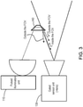
- FIG. 3 is a simplified schematic diagram illustrating a portion of the time-of-flight (TOF) imaging system 100 of FIG. 1 .
- FIG. 3 illustrates that the optical feedback device is configured to prevent light leakage from the optical feedback device 140 to the normal pixels in the array. Light inserted in the edge of the FOV can only hit specific pixels in the pixel array and light having different angle cannot enter the optics of the sensor.
- TOF time-of-flight
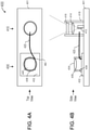
- FIGS. 4A and 4B are simplified diagrams illustrating a time-of-flight (TOF) imaging system 400 with fiber optic feedback for calibration according to an embodiment of the present invention.
- FIG. 4A is a top view and FIG. 4B is a side cross-sectional view of the imaging system.
- Imaging system 400 includes an illumination unit 410 and a sensor unit 430 disposed on a printed circuit board (PCB) 401. As shown in FIGS.
- PCB printed circuit board
- illumination unit 410 includes a diode laser source 412, a collimating lens 414, and a diffuser 416 inside an illumination housing 418.
- Sensor unit 430 includes an image sensor 432, a lens 434, and a lens barrel 436 that is mounted on the image sensor with an adhesive 438.
- Imaging system 400 also has an optical fiber 420 to provide the feedback path.
- optical fiber 420 collects certain amount of light from the interior of the illumination housing (e. g., from parasitic reflections inside) and directs it to a corner 442 of a pixel array 440 of image sensor 432, but outside lens barrel 436.
- opaque adhesive 438 blocks the light from entering the lens barrel.
- corner region 442 of the pixel array serves as the feedback region of the image sensor.
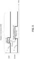
- FIG. 5 is a timing diagram illustrating a method for time-of-flight (TOF) depth measurement according to an embodiment of the present invention.
- the horizontal axis is the time
- the vertical axis is the intensity or magnitude of the light signal.
- Waveform 1 represents the light pulse arriving at the sensor, which can be reflected from the target or provided by the feedback optical device.
- Wave form 2 represents the shutter window. It can be seen that the light pulse has a width W light , and the shutter window has a width of W shutter . Further, there is a time delay between the leading edge of the light and the shutter, D L -> SH . It can be seen that the amount of light sensed by the sensor varies with the relative delay of the shutter with respect to the light.
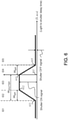
- FIG. 6 is a diagram illustrating the magnitude of sensed light signal versus light-to-shutter delay time according to some embodiments of the present invention.
- the horizontal axis is the light-to-shutter delay, D L -> SH
- the vertical axis is the amount of light sensed by the sensor.
- the diagram is divided into several regions, 601 to 605, In region 601, the shutter window is far ahead of the light pulse (to the left) and the shutter is already closed before the light arrives. In other words, the light-to-shutter delay is negative. Thus, there is no overlap between the shutter and the light. The delay increases moving to the right of the horizontal axis. At point 611, the shutter starts to overlap with the light.
- the delay increases further through region 602, the overlap between the shutter and the light continues to increase, and more light is sensed, resulting in the rising curve in region 602.
- the full width of the light starts to overlap with the shutter window.
- the shutter is fully open throughout the duration of the light pulse, and the width of region 603 is determined by the width of the shutter opening W shutter minus the width of the light pulse W light .
- the magnitude of light received in this region is marked "Shutter ON signal.”
- the rising edge of the shutter window is aligned with the rising edge of the light pulse, and the delay D L -> SH is zero, as marked by point 617.
- the delay D L -> SH continues to increase, and the overlap between the shutter window and the light decreases.
- the magnitude of the sensed light decreases in this region, as shown by the declining curve.
- the delay is equal to the light width, and the shutter opens as the light pulse ends; as a result, no light is sensed.
- the shutter opens after the light pulse has already passed. No light is sensed in region 605, and the amount of sensed light in this region is marked "Shutter OFF signal.”
- the amount of light collected by the sensor varies depending on the light-to-shutter delay, D L -> SH .
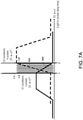
- FIG. 7A is a diagram illustrating sensed light signals versus light-to-shutter delay times of two signals with two shutters according to an embodiment of the present invention.
- the time-of-flight (TOF) camera acquires depth images by determining the time which light needs from a source to an object and reflected back to the camera. This can be done by illuminating the object or scene with a light pulse and applying a convolution of a sequence of windows with varying delay times to the received optical signal by the sensor.
- multiple groups of calibration light pulses are transmitted using a sequence of shutter windows that includes delay times representing a range of depth. Each group of light pulses is followed by a readout operation.
- the light from the optical feedback device is sensed in the feedback region of the pixel array of the sensor.
- the readout data is then analyzed using a convolution process to determine TOF depth data.
- the amount of light collected at the sensor varies depending on the light-to-shutter delay, D L -> SH .
- Sensed light data similar to that in FIG. 6 can be collected. These regions are used in TOF depth measurement calibration.
- FIG. 7A two calibration sequences can be carried out to reduce the effect of unknown reflectivity of the target object; and the two sequences are denoted S1 and S2.
- the difference in light-to-shutter delay, DL->SH for the two sequences is equal to the width of the shutter window W shutter .
- region 604 of sequence S1 and region 602 of sequence S2 can be aligned in the plot of FIG. 7A and form slices t-1, t-2, ..., t-k.
- the amount of light collected in S1 and S2, respectively represents two portions of the reflected light pulse, and the ratio of S2/S1 is related to a corresponding depth or distance to the target object.
- the region between points A and B in FIG. 7A represents the depth range that can be determined by this TOF imager. Data of received light can be collected by measuring at multiple points with delays between A and B in front of a target.
- a look up table can be constructed that relates the ratio S2/S1 to the depth or distance to the target.
- the initial lookup table can be constructed in the factory calibration process.
- two measurements are made with delays from the same slice of time in FIG. 7A .
- a ratio of sensed light S2/S1 is determined based on sensed data, and the corresponding depth can be determined from the look up table.
- FIG. 7B is a diagram illustrating simulated signals versus light-to-shutter delay times of two signals with two shutters according to an embodiment of the present invention.
- the simulation was carried out with two shutters on a static test with a flat target at 100 cm from the camera, scanning a range of the light-to-shutter delays. Similar to FIG. 7A , the shutter signal (or the number of photo-electrons collected at the sensor) is plotted for two shutters S1 and S2. In this view, depth can be negative.
- the width of the light pulse is 5 - 10 nsec, and the shutter window width is 5-15 nsec.
- the range of delays examined is between 5 -20 nsec.
- the light pulse width can be between 3 nsec to 20 sec.
- the width of the shutter can be in the same range.
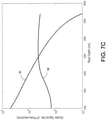
- FIG. 7C is a diagram illustrating simulated signals versus depth for two signals with two shutters according to an embodiment of the present invention.
- FIG. 7C shows data as measured on a rail against a wall at different distances (with 1/distance 2 decay). It can be seen that there is a correlation between the ratio of S2/S1 and the depth.
- a look up table (LUT) is constructed in the factory calibration process.
- a ratio of S2/S1 is determined based on sensed data, and the corresponding depth can be determined from the lookup table.
- time-of-flight depth measurement systems can be susceptible to variations in process and operating conditions, such as temperature, voltage, and frame rate, etc.
- embodiments of the invention provide a system and method for run-time calibration of TOF depth measurement using an optical feedback device as described above.
- the small number of feedback pixels allows for fast sensing and signal processing, and with the strong feedback illumination, for example provided by optical fiber, the number of sampling pulses can be greatly reduced.
- the process of illumination and readout can be carried out in a short time.
- the depth calibration can be carried out at run-time without affecting the frame rate of the camera.
- the calibration can be carried out in each frame.
- the overhead in power consumption or dedicated feedback pixels is small. Isolation between the feedback region and active region of the pixel array is provided to minimize interference.
- FIG. 8 is a timing diagram illustrating a method for depth profile calibration between frames of time-of-flight depth measurement according to an embodiment of the present invention.
- the method includes a stabilization period 810, a calibration period 820, and a measurement period 830.
- stabilization period 810 thermal stabilization illumination pulses are emitted, followed by a dummy readout for thermal stabilization of the sensor.
- calibration period 820 the time-of-flight lookup table (LUT) is calibrated.
- multiple groups of calibration illumination pulses P-1, P-2, ..., P-N are emitted using a sequence of shutter windows that includes delay times representing a range of depth.
- Each group of light pulses is followed by a readout operation, R-1, R-2, ..., R-N, respectively.
- the light from the optical feedback device are sensed in the feedback region of the pixel array of the sensor.
- the readout data is then analyzed using a convolution process to determine TOF depth data as described above in connections with FIGS. 5 , 6 , and 7A-7C .
- the depth data is then used to calibrate the lookup table.
- the measurement period 830 has two steps 831 and 832.
- a first group of light pulses S1 with a first shutter delay D1 is transmitted to illuminate the target. Because only a small amount of light can be collected by the sensor within a shutter window, often a large number, e.g., several thousand, pulses are sent out and gathered to increase the signal to noise ratio.
- the "S1 read" period the light reflected from the target is sensed in the active region of the pixels in the sensor.
- a second group of light pulses S2 with a second shutter delay D2 is transmitted to illuminate the target.
- S2 read the light reflected from the target is sensed in the active region of the pixels in the sensor.
- the ratio of sensed data readouts S2/S1 are used to determine the distance of the target object using the calibrated look up table.
- S1 and S2 have preset delays that are chosen in the factory calibration process or in the field of application.
- FIG. 9 is a timing diagram illustrating that the depth profile calibration can fit in between frames of time-of-flight depth measurement according to an embodiment of the present invention.
- FIG. 9 is similar to FIG. 8 , and further includes examples of the length of time each operation takes within a frame of time-of-flight depth measurement.
- the thermal stabilization pulses take 0.15 msec
- the dummy readout for thermal stabilization takes 0. 1 msec. Therefore, the length of the stabilization period is about 0.25 msec.
- LUT look up table
- each step includes 30 pulses, each having a pulse width of 150 nsec, followed by a read out operation of 3 ⁇ sec.
- the calibration period takes about 0.15 msec.
- the S1 step can include 1.5 msec of light pulses (e.g., 1,000 pulses of 150 nsec pulses) followed by a 0.5 msec readout.
- the S2 step can include 2.0 msec of light pulses, followed by a 0.5 msec readout.
- the complete operation including stabilization, full range depth calibration, and TOF depth measurement takes 4.9 msec.
- the calibration phase takes about 1/300 of the total operation. This optical operation is fast enough to fit in a frame rate of 60 or more frames per second (fps).
- the feedback optical device can provide strong light for calibration.
- the feedback optical device can include optical fiber.
- One or more separate feedback regions in the pixel array are used for sensing the feedback optical signal.
- the feedback regions are configured in unused or less used regions of the pixel array, and is much smaller than the active region of the array. For example, several pixels are sufficient for feedback sensing if the feedback optical device can provide a strong signal.
- the small feedback sensing region enables quick sensing and fast processing of sensed data, allowing fast calibration of the depth range of interest.
- FIG. 10 is a simplified flowchart illustrating a method for TOF depth measurement including full range depth calibration according to an embodiment of the present invention.
- method 1000 includes transmitting light pulses to illuminate a target object, at step 1010.
- step 1020 light provided from an optical feedback device is sensed in a first region of a light-sensitive pixel array.
- the first region is used as the feedback region.
- the optical feedback device receives a portion of the transmitted light pulses.
- the feedback optical device includes a preset reference depth for TOF depth measure.
- the light from the optical feedback device is sampled using a sequence of shutter windows that includes delay times representing a range of distances.
- the method includes sensing, in a second region of the light-sensitive pixel array, the scene data which is light reflected from the target object from the transmitted light pulses, at step 1030.
- the second region is the active region of the pixel array.
- the method includes calibrating time-of-flight (TOF) depth measurement reference information based on the sensed light in the first region of the pixel array, at step 1040.
- TOF time-of-flight
- steps 1030 and 1040 can be carried out in any order. For example, after the calibration data (1020) and the scene data (1040) are captured, data calibration can be processed first and then the scene data is processed. Alternative, both TOF data calibration and scene data processing can be carried out simultaneously.
- the method includes, at step 1050, determining a distance of the target object based on the sensed reflected light and the calibrated TOF measurement reference information.
- the method can be carried out in a digital camera characterized by a preset frame rate.
- the calibration can fit in a single frame period of the camera.
- the light from the optical feedback device is sampled using a sequence of shutter windows that includes delay times representing a range of distance. A convolution process is then used to correlate the measured signals with the distance.
- Embodiments of the invention provide integrated mechanics, electronics, and optics design and processing procedures to form a miniature circuit for optical feedback for high speed time-of-flight (TOF) signal from the illumination portion into the corner pixels within the image sensor.
- the design includes high level of integration, efficient transfer of light in the feedback loop to save energy consumption, and robustness over production tolerances.
- the embodiments can also avoid occlusion in the imaging optics, not add constraints on the back focal length of the objective lens, and avoid leakage of light from the feedback loop into the imaging area, and vice versa. Further details are described below.
- FIG. 11 is a perspective view diagram illustrating a portion of time-of-flight (TOF) imaging system 1100 with fiber optic feedback for calibration according to an embodiment of the present invention.
- Imaging system 1100 includes an illumination unit 1110 and a sensor unit 1130 disposed on a printed circuit board (PCB) 1101.
- illumination unit 1110 includes a laser diode source 1112, an illumination optics 1114, and a diffuser 1116.
- the illumination optics 1114 is disposed in a cavity 1118 in the PCB 1101, and can include prisms with integrated lenses to fold and collimate the light beam from the laser diode.
- Sensor unit 1130 includes an image sensor 1132 with a pixel array 1136, and an objective lens 1134 (shown in broken lines) mounted on the image sensor 1132.
- emitted light 1111 from diffuser 1116 is directed to a target object disposed above and outside the drawings in FIG. 11 , and light 1131 reflected from the target object enters through objective lens 1134 to reach the pixel array in image sensor 1132.
- Imaging system 1100 also has an optical fiber 1120 to provide the feedback path. In this embodiment, an optical fiber 1120 collects a small amount of light from the interior of the illumination optics housing (e.
- corner region 1142 of the pixel array serves as the feedback region of the image sensor.
- FIG 12 is a cross-sectional plan view of a portion of time-of-flight (TOF) imaging system 1100 of FIG. 11 according to an embodiment of the present invention.
- a laser diode 1112 is coupled to the base of the housing of the illumination unit.
- An optical fiber 1120 collects a small amount of light from the interior of the illumination optics housing (e. g., from parasitic reflections inside) and directs it to a prism 1138 that is attached to a corner 1142 of the pixel array of image sensor 1132. In some embodiments, no specific optical element in the illumination unit housing is needed to direct a portion of the laser light to the optical fiber 1120.
- Optical fiber 1120 directs the light to prism 1138 attached to a sample area 1142 of the pixel array. In this embodiment, scattered light from the illumination housing is collected by the optical fiber 1120, and scattered light from the prism 1138 can be sensed in the feedback sense area 1142 of the pixel array.
- optical fiber 1120 is coupled to the hypotenuse of the prism 1138.
- the coupling can also be made to a short side (cathetus) of the prism, as shown in FIGS. 13 and 14 .
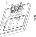
- FIG 13 is a perspective view of a portion of time-of-flight (TOF) imaging system 1100 of FIG. 11 according to an embodiment of the present invention.
- a laser diode 1112 is coupled to the base of the housing of the illumination unit.
- An optical fiber 1120 collects a small amount of light from the interior of the illumination optics housing (e. g., from parasitic reflections inside) and directs it to a prism 1138 that is attached to a corner 1142 of the pixel array 1136 of image sensor 1132.
- scattered light from the illumination housing is collected by the optical fiber 1120.
- Optical fiber 1120 directs the scattered light to prism 1138, which is attached to a sample area 1142 of the pixel array 1136. Light from the prism 1138 can be sensed in the feedback sense area 1142 of the pixel array 1136 for calibration.
- FIG 14 is a cross-sectional plan view of a portion of time-of-flight (TOF) imaging system 1100 of FIG. 11 according to an embodiment of the present invention.
- a laser diode 1112 is coupled to the base of the housing of the illumination unit.
- An optical fiber 1120 collects a small amount of scattered light from the interior of the illumination optics housing (e. g., from parasitic reflections inside) and directs it to a prism 1138 that is attached to a corner 1142 of the pixel array of image sensor 1132.
- Optical fiber 1120 directs the light to prism 1138 attached to a sample area 1142 of the pixel array. Light from the prism 1138 can be sensed in the feedback sense area 1142 of the pixel array 1136.
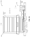
- FIG. 15 is a cross-sectional side view of a portion of time-of-flight (TOF) imaging system 1100 of FIG. 11 according to an embodiment of the present invention.
- Imaging system 1100 in FIG. 15 includes an illumination unit 1110 and a sensor unit 1130 disposed on a printed circuit board (PCB) 1101.
- illumination unit 1110 includes a laser diode source (not shown), an illumination optics 1114.
- Sensor unit 1130 includes an image sensor 1132 with a pixel array 1136, and an objective lens 1134 mounted on the image sensor 1132.
- emitted light 1111 from illumination unit 1110 is directed to a target object disposed above and outside the drawings in FIG.
- Imaging system 1100 also has an optical fiber 1120 to provide the feedback path.
- optical fiber 1120 collects a small amount of scattered light from the interior of the illumination optics housing and directs it to a prism 1138 that is attached to a corner 1142 of the pixel array 1136 of image sensor 1132.
- corner region 1142 of the pixel array serves as the feedback region of the image sensor.
- FIG. 16 is another perspective view diagram illustrating a portion of time-of-flight (TOF) imaging system 1100 with fiber optic feedback for calibration according to an embodiment of the present invention.
- illumination unit 1110 includes a laser diode source 1112, an illumination optics 1114, and a diffuser 1116.
- the illumination optics 1114 is disposed in a cavity 1118 in the PCB 1101, and can include prisms with integrated lenses to fold and collimate the light beam from the laser diode.
- Sensor unit 1130 includes an image sensor with a pixel array 1136, and an objective lens 1134 (shown in broken lines) mounted on the image sensor 1132. As shown in FIG.
- emitted light 1111 from diffuser 1116 is directed to a target object disposed above and outside the drawings in FIG. 11 , and light 1131 reflected from the target object enters through objective lens 1134 to reach the pixel array 1136 in the image sensor.
- the Imaging system also has an optical fiber 1120 to provide a feedback path.
- optical fiber 1120 collects a small amount of light from the interior of the illumination optics housing (e. g., from parasitic reflections inside) and directs it to a prism 1138 that is attached to a corner 1142 of the pixel array of image sensor 1132.
- corner region 1142 of the pixel array serves as the feedback region of the image sensor.
- light beam A goes from the laser into a folding surface of the prism in the illumination optics 1114.
- Light beam A1 reflected back from the prism entrance as stray light into a cavity in the illumination unit.
- Light beam B exits collimated from the prism and is directed to the diffuser 1115.
- Light beam B1 is reflected back from the diffuser as stray light into the cavity.
- the stray light from the cavity is collected by the optical fiber 1120.
- the amount of stray light was measured by using a fiber connect to optical power meter to verify that enough light signal can be collected for feedback calibration.
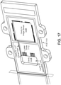
- FIG. 17 is a perspective view diagram illustrating the printed circuit board (PCB) 1101 of the time-of-flight (TOF) imaging system 1100 with fiber optic feedback for calibration according to an embodiment of the present invention.
- PCB 1101 includes a first cavity 1118 for the illumination unit, a second cavity 1139 for the image sensor, and a third cavity 1121 for the optical fiber.
- FIG. 17 also illustrates a laser diode 1112 disposed on PCB 1101.
- FIG. 18 is a perspective view diagram illustrating a prism 1138 that can be used in the time-of-flight (TOF) imaging system 1100 with fiber optic feedback for calibration according to an embodiment of the present invention.
- the prism can be made of glass, or other suitable transparent optical material.
- the prism has a top surface and a bottom surface, both labeled as surface "1," and three side surfaces each labeled as surface "2.” As illustrated in FIGS. 11-16 , the light from the optical fiber enters the prism through one of the side surfaces 2 and exits through the bottom surface 1 to be coupled into the pixel array in the image sensor. Therefore, in some embodiments, the top surface and two of the side surfaces of the prism are coated with reflective coating.
- the bottom surface and one of the side surfaces are uncoated and remains clear to allow the light from the optical fiber to enter the prism through a side surface and exit the prism through the bottom surface.
- the prism is glued with a transparent adhesive to the pixel array and then coated with an opaque paste to isolate the feedback optics from the imaging optics.
- optical fiber 1120 is coupled to the hypotenuse of the prism 1138, and a short side of the prism is disposed to overlap with the pixel array.
- a simulation study shows that in these embodiments, about 5.8% of the light coming through the fiber reaches the pixels area.
- optical fiber 1120 is coupled to a short side of the prism 1138, and the hypotenuse of the prism is disposed to overlap with the pixel array.
- a simulation study shows that in these embodiments, about 8.7% of the light coming through the fiber reaches the pixels area.
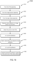
- FIG. 19 is a flowchart illustrating a method for forming a time-of-flight (TOF) imaging system with fiber optic feedback for calibration according to an embodiment of the present invention.
- the method includes forming the PCB assembly.
- the method includes forming the image sensor assembly by chip-on-board (CoB), in process 1920.
- the laser diode assembly is formed by chip-on-board (CoB).
- the method includes dispense clear adhesive on image sensor for the optical feedback (OFB) prism in process 1940.
- the OFB prism refers to optics that folds a direct light from the illumination unit into the field of view (FOV) of the lens.
- the prism is attached to the PCB, in process 1950, and the adhesive is cured using a UV cure process (1960).
- the method also includes attaching optical fiber and dispensing clear adhesive during the attach time, in process 1970, and performing UV cure in process 1980. Further, in process 1990, the method includes dispensing absorbing adhesive material on the prism and on the clear adhesive.
- the optical fiber can be a 250 ⁇ m, optical grade unjacketed plastic optical fiber.
- Other suitable optical fiber can also be used in alternative embodiments.
- the adhesive material mentioned above can be a precision positioning optical adhesive or a suitable alternative adhesive material.
Landscapes
- Engineering & Computer Science (AREA)
- Physics & Mathematics (AREA)
- General Physics & Mathematics (AREA)
- Remote Sensing (AREA)
- Computer Networks & Wireless Communication (AREA)
- Radar, Positioning & Navigation (AREA)
- Electromagnetism (AREA)
- Optics & Photonics (AREA)
- Computer Vision & Pattern Recognition (AREA)
- Theoretical Computer Science (AREA)
- Optical Radar Systems And Details Thereof (AREA)
- Measurement Of Optical Distance (AREA)
- Length Measuring Devices By Optical Means (AREA)
Applications Claiming Priority (2)
| Application Number | Priority Date | Filing Date | Title |
|---|---|---|---|
| US201662402770P | 2016-09-30 | 2016-09-30 | |
| PCT/US2017/054719 WO2018064658A1 (en) | 2016-09-30 | 2017-10-02 | Real time calibration for time-of-flight depth measurement |
Publications (3)
| Publication Number | Publication Date |
|---|---|
| EP3519852A1 EP3519852A1 (en) | 2019-08-07 |
| EP3519852A4 EP3519852A4 (en) | 2019-10-16 |
| EP3519852B1 true EP3519852B1 (en) | 2022-03-23 |
Family
ID=61757220
Family Applications (1)
| Application Number | Title | Priority Date | Filing Date |
|---|---|---|---|
| EP17857610.4A Active EP3519852B1 (en) | 2016-09-30 | 2017-10-02 | Real time calibration for time-of-flight depth measurement |
Country Status (9)
| Country | Link |
|---|---|
| US (2) | US10762651B2 (ja) |
| EP (1) | EP3519852B1 (ja) |
| JP (2) | JP6882461B2 (ja) |
| KR (1) | KR102505237B1 (ja) |
| CN (1) | CN110402397B (ja) |
| AU (1) | AU2017337124B2 (ja) |
| CA (1) | CA3037988A1 (ja) |
| IL (1) | IL265659B (ja) |
| WO (1) | WO2018064658A1 (ja) |
Families Citing this family (22)
| Publication number | Priority date | Publication date | Assignee | Title |
|---|---|---|---|---|
| US10762651B2 (en) | 2016-09-30 | 2020-09-01 | Magic Leap, Inc. | Real time calibration for time-of-flight depth measurement |
| EP4095913B1 (en) | 2017-12-13 | 2024-09-25 | Magic Leap, Inc. | Global shutter pixel circuit |
| JP7046189B2 (ja) | 2017-12-21 | 2022-04-01 | マジック リープ, インコーポレイテッド | 拡張現実デバイスを較正する方法 |
| JP7418340B2 (ja) | 2018-03-13 | 2024-01-19 | マジック リープ, インコーポレイテッド | 機械学習を使用した画像増強深度感知 |
| JP7082404B2 (ja) * | 2018-06-26 | 2022-06-08 | 国立大学法人静岡大学 | 距離計測装置 |
| JP6717887B2 (ja) * | 2018-07-12 | 2020-07-08 | ファナック株式会社 | 距離補正機能を有する測距装置 |
| CN110868507A (zh) * | 2018-08-27 | 2020-03-06 | 宁波舜宇光电信息有限公司 | 带有泛光灯的电子设备及其装配方法 |
| WO2020055619A1 (en) * | 2018-09-16 | 2020-03-19 | Nephelai Research Llc | Calibration of a depth sensing array using color image data |
| CN109067951A (zh) * | 2018-10-31 | 2018-12-21 | Oppo广东移动通信有限公司 | 电子装置 |
| EP3657203A1 (de) * | 2018-11-22 | 2020-05-27 | Hexagon Technology Center GmbH | Elektrooptischer entfernungsmesser und entfernungsmessverfahren |
| DE102019134142A1 (de) * | 2018-12-12 | 2020-06-18 | Analog Devices, Inc. | Eingebaute kalibrierung von laufzeittiefenbildgebungssystemen |
| US11423572B2 (en) * | 2018-12-12 | 2022-08-23 | Analog Devices, Inc. | Built-in calibration of time-of-flight depth imaging systems |
| CN109451228B (zh) | 2018-12-24 | 2020-11-10 | 华为技术有限公司 | 摄像组件及电子设备 |
| CN111580117A (zh) * | 2019-02-19 | 2020-08-25 | 光宝电子(广州)有限公司 | 飞时测距感测系统的控制方法 |
| EP3930321A4 (en) * | 2019-03-25 | 2022-04-20 | Huawei Technologies Co., Ltd. | DUAL CAMERA + TOF LARGE APERTURE BLUR PROCESS |
| TWI748460B (zh) * | 2019-06-21 | 2021-12-01 | 大陸商廣州印芯半導體技術有限公司 | 飛時測距裝置及飛時測距方法 |
| EP3816657B1 (en) * | 2019-10-29 | 2024-04-24 | Hexagon Technology Center GmbH | Multi-beam measuring device for 3d scanning of an environment having seamlessly stacked reception modules |
| CN112924979B (zh) * | 2019-11-20 | 2024-03-01 | 北京小米移动软件有限公司 | Tof模组的多路径光线测试设备、深度误差测量方法及系统 |
| CN111024368B (zh) * | 2019-12-06 | 2022-02-11 | 炬佑智能科技(苏州)有限公司 | Tof相机杂散光检测装置及检测方法 |
| US11582436B2 (en) * | 2020-07-17 | 2023-02-14 | Shenzhen GOODIX Technology Co., Ltd. | Passive three-dimensional image sensing based on chromatic focal differentiation |
| JPWO2022145261A1 (ja) * | 2020-12-28 | 2022-07-07 | ||
| JP2023122396A (ja) * | 2022-02-22 | 2023-09-01 | ソニーセミコンダクタソリューションズ株式会社 | 測距装置 |
Family Cites Families (16)
| Publication number | Priority date | Publication date | Assignee | Title |
|---|---|---|---|---|
| US7212278B2 (en) | 2001-08-06 | 2007-05-01 | Siemens Aktiengesellschaft | Method and device for recording a three-dimensional distance-measuring image |
| JP2010061304A (ja) * | 2008-09-02 | 2010-03-18 | Calsonic Kansei Corp | 車両用距離画像データ生成装置 |
| EP2477043A1 (en) * | 2011-01-12 | 2012-07-18 | Sony Corporation | 3D time-of-flight camera and method |
| US8872093B2 (en) | 2012-04-18 | 2014-10-28 | Apple Inc. | Calibrated image-sensor-based ambient light sensor |
| JP2014070936A (ja) | 2012-09-28 | 2014-04-21 | Dainippon Screen Mfg Co Ltd | 誤差画素検出装置、誤差画素検出方法、および誤差画素検出プログラム |
| US10230934B2 (en) * | 2013-06-14 | 2019-03-12 | Microsoft Tehcnology Licensing, Llc | Depth map correction using lookup tables |
| US10063844B2 (en) * | 2013-10-17 | 2018-08-28 | Microsoft Technology Licensing, Llc. | Determining distances by probabilistic time of flight imaging |
| US9542749B2 (en) | 2014-01-06 | 2017-01-10 | Microsoft Technology Licensing, Llc | Fast general multipath correction in time-of-flight imaging |
| EP3112901A4 (en) * | 2014-02-28 | 2017-03-01 | Panasonic Intellectual Property Management Co., Ltd. | Distance measuring apparatus and distance measuring method |
| US10062180B2 (en) | 2014-04-22 | 2018-08-28 | Microsoft Technology Licensing, Llc | Depth sensor calibration and per-pixel correction |
| US9720076B2 (en) * | 2014-08-29 | 2017-08-01 | Omnivision Technologies, Inc. | Calibration circuitry and method for a time of flight imaging system |
| US9578311B2 (en) | 2014-10-22 | 2017-02-21 | Microsoft Technology Licensing, Llc | Time of flight depth camera |
| US9823352B2 (en) * | 2014-10-31 | 2017-11-21 | Rockwell Automation Safety Ag | Absolute distance measurement for time-of-flight sensors |
| US9330464B1 (en) * | 2014-12-12 | 2016-05-03 | Microsoft Technology Licensing, Llc | Depth camera feedback |
| US10762651B2 (en) | 2016-09-30 | 2020-09-01 | Magic Leap, Inc. | Real time calibration for time-of-flight depth measurement |
| DE102017126378A1 (de) * | 2017-11-10 | 2019-05-16 | Infineon Technologies Ag | Verfahren zum Verarbeiten eines Rohbildes einer Time-of-Flight-Kamera, Bildverarbeitungsvorrichtung und Computerprogramm |
-
2017
- 2017-09-29 US US15/721,640 patent/US10762651B2/en active Active
- 2017-10-02 JP JP2019517427A patent/JP6882461B2/ja active Active
- 2017-10-02 WO PCT/US2017/054719 patent/WO2018064658A1/en unknown
- 2017-10-02 AU AU2017337124A patent/AU2017337124B2/en not_active Ceased
- 2017-10-02 KR KR1020197012442A patent/KR102505237B1/ko active IP Right Grant
- 2017-10-02 CN CN201780073708.1A patent/CN110402397B/zh active Active
- 2017-10-02 EP EP17857610.4A patent/EP3519852B1/en active Active
- 2017-10-02 CA CA3037988A patent/CA3037988A1/en active Pending
-
2019
- 2019-03-27 IL IL265659A patent/IL265659B/en unknown
-
2020
- 2020-07-22 US US16/936,345 patent/US11587245B2/en active Active
-
2021
- 2021-05-06 JP JP2021078354A patent/JP7130813B2/ja active Active
Also Published As
| Publication number | Publication date |
|---|---|
| JP2021113828A (ja) | 2021-08-05 |
| AU2017337124A1 (en) | 2019-04-18 |
| US20180096489A1 (en) | 2018-04-05 |
| EP3519852A1 (en) | 2019-08-07 |
| WO2018064658A1 (en) | 2018-04-05 |
| AU2017337124B2 (en) | 2022-08-04 |
| KR20190054167A (ko) | 2019-05-21 |
| KR102505237B1 (ko) | 2023-02-28 |
| IL265659A (en) | 2019-05-30 |
| US20210004975A1 (en) | 2021-01-07 |
| CA3037988A1 (en) | 2018-04-05 |
| CN110402397A (zh) | 2019-11-01 |
| EP3519852A4 (en) | 2019-10-16 |
| JP7130813B2 (ja) | 2022-09-05 |
| US10762651B2 (en) | 2020-09-01 |
| US11587245B2 (en) | 2023-02-21 |
| JP6882461B2 (ja) | 2021-06-02 |
| CN110402397B (zh) | 2023-03-03 |
| IL265659B (en) | 2022-04-01 |
| JP2019529931A (ja) | 2019-10-17 |
Similar Documents
| Publication | Publication Date | Title |
|---|---|---|
| EP3519852B1 (en) | Real time calibration for time-of-flight depth measurement | |
| EP4095913B1 (en) | Global shutter pixel circuit | |
| CN108267749A (zh) | 校准飞行时间光学系统的光检测器 | |
| US11463675B2 (en) | Light-source characterizer and associated methods | |
| EP3593166A1 (en) | Integrated lidar illumination power control | |
| JP2019529931A5 (ja) | ||
| CA3062701A1 (en) | Lidar data acquisition and control | |
| CA2716980C (en) | Light-integrating rangefinding device and method | |
| CN111352120B (zh) | 飞行时间测距系统及其测距方法 | |
| US10514447B2 (en) | Method for propagation time calibration of a LIDAR sensor | |
| US10989605B2 (en) | Streak camera calibration | |
| CN113237891A (zh) | 一种检测系统 | |
| CN117191355A (zh) | 一种用于选通型像增强器的光学门宽测试装置及测试方法 | |
| CN104976985B (zh) | 一种图像测距仪 | |
| JP2002165230A (ja) | 3次元画像検出装置 |
Legal Events
| Date | Code | Title | Description |
|---|---|---|---|
| STAA | Information on the status of an ep patent application or granted ep patent |
Free format text: STATUS: THE INTERNATIONAL PUBLICATION HAS BEEN MADE |
|
| PUAI | Public reference made under article 153(3) epc to a published international application that has entered the european phase |
Free format text: ORIGINAL CODE: 0009012 |
|
| STAA | Information on the status of an ep patent application or granted ep patent |
Free format text: STATUS: REQUEST FOR EXAMINATION WAS MADE |
|
| 17P | Request for examination filed |
Effective date: 20190419 |
|
| AK | Designated contracting states |
Kind code of ref document: A1 Designated state(s): AL AT BE BG CH CY CZ DE DK EE ES FI FR GB GR HR HU IE IS IT LI LT LU LV MC MK MT NL NO PL PT RO RS SE SI SK SM TR |
|
| AX | Request for extension of the european patent |
Extension state: BA ME |
|
| A4 | Supplementary search report drawn up and despatched |
Effective date: 20190913 |
|
| RIC1 | Information provided on ipc code assigned before grant |
Ipc: G06T 7/00 20170101ALI20190910BHEP Ipc: G06F 3/01 20060101ALI20190910BHEP Ipc: G01S 17/08 20060101AFI20190910BHEP Ipc: G06K 9/00 20060101ALI20190910BHEP Ipc: G01S 7/497 20060101ALI20190910BHEP Ipc: G06K 7/10 20060101ALI20190910BHEP Ipc: G01S 17/89 20060101ALI20190910BHEP Ipc: H04N 5/225 20060101ALI20190910BHEP |
|
| DAV | Request for validation of the european patent (deleted) | ||
| DAX | Request for extension of the european patent (deleted) | ||
| STAA | Information on the status of an ep patent application or granted ep patent |
Free format text: STATUS: EXAMINATION IS IN PROGRESS |
|
| 17Q | First examination report despatched |
Effective date: 20210223 |
|
| RIC1 | Information provided on ipc code assigned before grant |
Ipc: G01S 7/481 20060101ALI20210902BHEP Ipc: G01S 17/894 20200101ALI20210902BHEP Ipc: G01S 7/497 20060101ALI20210902BHEP Ipc: H04N 5/225 20060101ALI20210902BHEP Ipc: G06T 7/00 20170101ALI20210902BHEP Ipc: G06K 9/00 20060101ALI20210902BHEP Ipc: G06K 7/10 20060101ALI20210902BHEP Ipc: G06F 3/01 20060101ALI20210902BHEP Ipc: G01S 17/89 20200101ALI20210902BHEP Ipc: G01S 17/08 20060101AFI20210902BHEP |
|
| GRAP | Despatch of communication of intention to grant a patent |
Free format text: ORIGINAL CODE: EPIDOSNIGR1 |
|
| STAA | Information on the status of an ep patent application or granted ep patent |
Free format text: STATUS: GRANT OF PATENT IS INTENDED |
|
| INTG | Intention to grant announced |
Effective date: 20211018 |
|
| GRAS | Grant fee paid |
Free format text: ORIGINAL CODE: EPIDOSNIGR3 |
|
| GRAA | (expected) grant |
Free format text: ORIGINAL CODE: 0009210 |
|
| STAA | Information on the status of an ep patent application or granted ep patent |
Free format text: STATUS: THE PATENT HAS BEEN GRANTED |
|
| AK | Designated contracting states |
Kind code of ref document: B1 Designated state(s): AL AT BE BG CH CY CZ DE DK EE ES FI FR GB GR HR HU IE IS IT LI LT LU LV MC MK MT NL NO PL PT RO RS SE SI SK SM TR |
|
| REG | Reference to a national code |
Ref country code: GB Ref legal event code: FG4D |
|
| REG | Reference to a national code |
Ref country code: CH Ref legal event code: EP |
|
| REG | Reference to a national code |
Ref country code: IE Ref legal event code: FG4D |
|
| REG | Reference to a national code |
Ref country code: DE Ref legal event code: R096 Ref document number: 602017055039 Country of ref document: DE |
|
| REG | Reference to a national code |
Ref country code: AT Ref legal event code: REF Ref document number: 1477820 Country of ref document: AT Kind code of ref document: T Effective date: 20220415 |
|
| REG | Reference to a national code |
Ref country code: NL Ref legal event code: FP |
|
| REG | Reference to a national code |
Ref country code: LT Ref legal event code: MG9D |
|
| PG25 | Lapsed in a contracting state [announced via postgrant information from national office to epo] |
Ref country code: SE Free format text: LAPSE BECAUSE OF FAILURE TO SUBMIT A TRANSLATION OF THE DESCRIPTION OR TO PAY THE FEE WITHIN THE PRESCRIBED TIME-LIMIT Effective date: 20220323 Ref country code: RS Free format text: LAPSE BECAUSE OF FAILURE TO SUBMIT A TRANSLATION OF THE DESCRIPTION OR TO PAY THE FEE WITHIN THE PRESCRIBED TIME-LIMIT Effective date: 20220323 Ref country code: NO Free format text: LAPSE BECAUSE OF FAILURE TO SUBMIT A TRANSLATION OF THE DESCRIPTION OR TO PAY THE FEE WITHIN THE PRESCRIBED TIME-LIMIT Effective date: 20220623 Ref country code: LT Free format text: LAPSE BECAUSE OF FAILURE TO SUBMIT A TRANSLATION OF THE DESCRIPTION OR TO PAY THE FEE WITHIN THE PRESCRIBED TIME-LIMIT Effective date: 20220323 Ref country code: HR Free format text: LAPSE BECAUSE OF FAILURE TO SUBMIT A TRANSLATION OF THE DESCRIPTION OR TO PAY THE FEE WITHIN THE PRESCRIBED TIME-LIMIT Effective date: 20220323 Ref country code: BG Free format text: LAPSE BECAUSE OF FAILURE TO SUBMIT A TRANSLATION OF THE DESCRIPTION OR TO PAY THE FEE WITHIN THE PRESCRIBED TIME-LIMIT Effective date: 20220623 |
|
| REG | Reference to a national code |
Ref country code: AT Ref legal event code: MK05 Ref document number: 1477820 Country of ref document: AT Kind code of ref document: T Effective date: 20220323 |
|
| PG25 | Lapsed in a contracting state [announced via postgrant information from national office to epo] |
Ref country code: LV Free format text: LAPSE BECAUSE OF FAILURE TO SUBMIT A TRANSLATION OF THE DESCRIPTION OR TO PAY THE FEE WITHIN THE PRESCRIBED TIME-LIMIT Effective date: 20220323 Ref country code: GR Free format text: LAPSE BECAUSE OF FAILURE TO SUBMIT A TRANSLATION OF THE DESCRIPTION OR TO PAY THE FEE WITHIN THE PRESCRIBED TIME-LIMIT Effective date: 20220624 Ref country code: FI Free format text: LAPSE BECAUSE OF FAILURE TO SUBMIT A TRANSLATION OF THE DESCRIPTION OR TO PAY THE FEE WITHIN THE PRESCRIBED TIME-LIMIT Effective date: 20220323 |
|
| PG25 | Lapsed in a contracting state [announced via postgrant information from national office to epo] |
Ref country code: SM Free format text: LAPSE BECAUSE OF FAILURE TO SUBMIT A TRANSLATION OF THE DESCRIPTION OR TO PAY THE FEE WITHIN THE PRESCRIBED TIME-LIMIT Effective date: 20220323 Ref country code: SK Free format text: LAPSE BECAUSE OF FAILURE TO SUBMIT A TRANSLATION OF THE DESCRIPTION OR TO PAY THE FEE WITHIN THE PRESCRIBED TIME-LIMIT Effective date: 20220323 Ref country code: RO Free format text: LAPSE BECAUSE OF FAILURE TO SUBMIT A TRANSLATION OF THE DESCRIPTION OR TO PAY THE FEE WITHIN THE PRESCRIBED TIME-LIMIT Effective date: 20220323 Ref country code: PT Free format text: LAPSE BECAUSE OF FAILURE TO SUBMIT A TRANSLATION OF THE DESCRIPTION OR TO PAY THE FEE WITHIN THE PRESCRIBED TIME-LIMIT Effective date: 20220725 Ref country code: ES Free format text: LAPSE BECAUSE OF FAILURE TO SUBMIT A TRANSLATION OF THE DESCRIPTION OR TO PAY THE FEE WITHIN THE PRESCRIBED TIME-LIMIT Effective date: 20220323 Ref country code: EE Free format text: LAPSE BECAUSE OF FAILURE TO SUBMIT A TRANSLATION OF THE DESCRIPTION OR TO PAY THE FEE WITHIN THE PRESCRIBED TIME-LIMIT Effective date: 20220323 Ref country code: CZ Free format text: LAPSE BECAUSE OF FAILURE TO SUBMIT A TRANSLATION OF THE DESCRIPTION OR TO PAY THE FEE WITHIN THE PRESCRIBED TIME-LIMIT Effective date: 20220323 Ref country code: AT Free format text: LAPSE BECAUSE OF FAILURE TO SUBMIT A TRANSLATION OF THE DESCRIPTION OR TO PAY THE FEE WITHIN THE PRESCRIBED TIME-LIMIT Effective date: 20220323 |
|
| PG25 | Lapsed in a contracting state [announced via postgrant information from national office to epo] |
Ref country code: PL Free format text: LAPSE BECAUSE OF FAILURE TO SUBMIT A TRANSLATION OF THE DESCRIPTION OR TO PAY THE FEE WITHIN THE PRESCRIBED TIME-LIMIT Effective date: 20220323 Ref country code: IS Free format text: LAPSE BECAUSE OF FAILURE TO SUBMIT A TRANSLATION OF THE DESCRIPTION OR TO PAY THE FEE WITHIN THE PRESCRIBED TIME-LIMIT Effective date: 20220723 Ref country code: AL Free format text: LAPSE BECAUSE OF FAILURE TO SUBMIT A TRANSLATION OF THE DESCRIPTION OR TO PAY THE FEE WITHIN THE PRESCRIBED TIME-LIMIT Effective date: 20220323 |
|
| REG | Reference to a national code |
Ref country code: DE Ref legal event code: R097 Ref document number: 602017055039 Country of ref document: DE |
|
| PLBE | No opposition filed within time limit |
Free format text: ORIGINAL CODE: 0009261 |
|
| STAA | Information on the status of an ep patent application or granted ep patent |
Free format text: STATUS: NO OPPOSITION FILED WITHIN TIME LIMIT |
|
| PG25 | Lapsed in a contracting state [announced via postgrant information from national office to epo] |
Ref country code: DK Free format text: LAPSE BECAUSE OF FAILURE TO SUBMIT A TRANSLATION OF THE DESCRIPTION OR TO PAY THE FEE WITHIN THE PRESCRIBED TIME-LIMIT Effective date: 20220323 |
|
| 26N | No opposition filed |
Effective date: 20230102 |
|
| PG25 | Lapsed in a contracting state [announced via postgrant information from national office to epo] |
Ref country code: SI Free format text: LAPSE BECAUSE OF FAILURE TO SUBMIT A TRANSLATION OF THE DESCRIPTION OR TO PAY THE FEE WITHIN THE PRESCRIBED TIME-LIMIT Effective date: 20220323 Ref country code: MC Free format text: LAPSE BECAUSE OF FAILURE TO SUBMIT A TRANSLATION OF THE DESCRIPTION OR TO PAY THE FEE WITHIN THE PRESCRIBED TIME-LIMIT Effective date: 20220323 |
|
| REG | Reference to a national code |
Ref country code: CH Ref legal event code: PL |
|
| PG25 | Lapsed in a contracting state [announced via postgrant information from national office to epo] |
Ref country code: LU Free format text: LAPSE BECAUSE OF NON-PAYMENT OF DUE FEES Effective date: 20221002 |
|
| P01 | Opt-out of the competence of the unified patent court (upc) registered |
Effective date: 20230607 |
|
| PG25 | Lapsed in a contracting state [announced via postgrant information from national office to epo] |
Ref country code: LI Free format text: LAPSE BECAUSE OF NON-PAYMENT OF DUE FEES Effective date: 20221031 Ref country code: IT Free format text: LAPSE BECAUSE OF FAILURE TO SUBMIT A TRANSLATION OF THE DESCRIPTION OR TO PAY THE FEE WITHIN THE PRESCRIBED TIME-LIMIT Effective date: 20220323 Ref country code: CH Free format text: LAPSE BECAUSE OF NON-PAYMENT OF DUE FEES Effective date: 20221031 |
|
| PG25 | Lapsed in a contracting state [announced via postgrant information from national office to epo] |
Ref country code: IE Free format text: LAPSE BECAUSE OF NON-PAYMENT OF DUE FEES Effective date: 20221002 |
|
| PGFP | Annual fee paid to national office [announced via postgrant information from national office to epo] |
Ref country code: NL Payment date: 20230922 Year of fee payment: 7 Ref country code: GB Payment date: 20230920 Year of fee payment: 7 |
|
| PGFP | Annual fee paid to national office [announced via postgrant information from national office to epo] |
Ref country code: FR Payment date: 20230920 Year of fee payment: 7 Ref country code: BE Payment date: 20230920 Year of fee payment: 7 |
|
| PGFP | Annual fee paid to national office [announced via postgrant information from national office to epo] |
Ref country code: DE Payment date: 20230920 Year of fee payment: 7 |
|
| PG25 | Lapsed in a contracting state [announced via postgrant information from national office to epo] |
Ref country code: HU Free format text: LAPSE BECAUSE OF FAILURE TO SUBMIT A TRANSLATION OF THE DESCRIPTION OR TO PAY THE FEE WITHIN THE PRESCRIBED TIME-LIMIT; INVALID AB INITIO Effective date: 20171002 |
|
| PG25 | Lapsed in a contracting state [announced via postgrant information from national office to epo] |
Ref country code: CY Free format text: LAPSE BECAUSE OF FAILURE TO SUBMIT A TRANSLATION OF THE DESCRIPTION OR TO PAY THE FEE WITHIN THE PRESCRIBED TIME-LIMIT Effective date: 20220323 |
|
| PG25 | Lapsed in a contracting state [announced via postgrant information from national office to epo] |
Ref country code: MK Free format text: LAPSE BECAUSE OF FAILURE TO SUBMIT A TRANSLATION OF THE DESCRIPTION OR TO PAY THE FEE WITHIN THE PRESCRIBED TIME-LIMIT Effective date: 20220323 |