US9542749B2 - Fast general multipath correction in time-of-flight imaging - Google Patents
Fast general multipath correction in time-of-flight imaging Download PDFInfo
- Publication number
- US9542749B2 US9542749B2 US14/148,184 US201414148184A US9542749B2 US 9542749 B2 US9542749 B2 US 9542749B2 US 201414148184 A US201414148184 A US 201414148184A US 9542749 B2 US9542749 B2 US 9542749B2
- Authority
- US
- United States
- Prior art keywords
- camera
- depth
- values
- time
- flight
- Prior art date
- Legal status (The legal status is an assumption and is not a legal conclusion. Google has not performed a legal analysis and makes no representation as to the accuracy of the status listed.)
- Active, expires
Links
Images


Classifications
-
- G06T7/0061—
-
- G—PHYSICS
- G06—COMPUTING; CALCULATING OR COUNTING
- G06T—IMAGE DATA PROCESSING OR GENERATION, IN GENERAL
- G06T7/00—Image analysis
- G06T7/50—Depth or shape recovery
- G06T7/55—Depth or shape recovery from multiple images
- G06T7/593—Depth or shape recovery from multiple images from stereo images
-
- G—PHYSICS
- G01—MEASURING; TESTING
- G01S—RADIO DIRECTION-FINDING; RADIO NAVIGATION; DETERMINING DISTANCE OR VELOCITY BY USE OF RADIO WAVES; LOCATING OR PRESENCE-DETECTING BY USE OF THE REFLECTION OR RERADIATION OF RADIO WAVES; ANALOGOUS ARRANGEMENTS USING OTHER WAVES
- G01S17/00—Systems using the reflection or reradiation of electromagnetic waves other than radio waves, e.g. lidar systems
- G01S17/02—Systems using the reflection of electromagnetic waves other than radio waves
- G01S17/06—Systems determining position data of a target
- G01S17/08—Systems determining position data of a target for measuring distance only
- G01S17/32—Systems determining position data of a target for measuring distance only using transmission of continuous waves, whether amplitude-, frequency-, or phase-modulated, or unmodulated
- G01S17/36—Systems determining position data of a target for measuring distance only using transmission of continuous waves, whether amplitude-, frequency-, or phase-modulated, or unmodulated with phase comparison between the received signal and the contemporaneously transmitted signal
-
- G—PHYSICS
- G01—MEASURING; TESTING
- G01S—RADIO DIRECTION-FINDING; RADIO NAVIGATION; DETERMINING DISTANCE OR VELOCITY BY USE OF RADIO WAVES; LOCATING OR PRESENCE-DETECTING BY USE OF THE REFLECTION OR RERADIATION OF RADIO WAVES; ANALOGOUS ARRANGEMENTS USING OTHER WAVES
- G01S17/00—Systems using the reflection or reradiation of electromagnetic waves other than radio waves, e.g. lidar systems
- G01S17/88—Lidar systems specially adapted for specific applications
- G01S17/89—Lidar systems specially adapted for specific applications for mapping or imaging
- G01S17/894—3D imaging with simultaneous measurement of time-of-flight at a 2D array of receiver pixels, e.g. time-of-flight cameras or flash lidar
-
- G—PHYSICS
- G01—MEASURING; TESTING
- G01S—RADIO DIRECTION-FINDING; RADIO NAVIGATION; DETERMINING DISTANCE OR VELOCITY BY USE OF RADIO WAVES; LOCATING OR PRESENCE-DETECTING BY USE OF THE REFLECTION OR RERADIATION OF RADIO WAVES; ANALOGOUS ARRANGEMENTS USING OTHER WAVES
- G01S7/00—Details of systems according to groups G01S13/00, G01S15/00, G01S17/00
- G01S7/48—Details of systems according to groups G01S13/00, G01S15/00, G01S17/00 of systems according to group G01S17/00
- G01S7/497—Means for monitoring or calibrating
-
- G06T7/0075—
-
- G—PHYSICS
- G06—COMPUTING; CALCULATING OR COUNTING
- G06T—IMAGE DATA PROCESSING OR GENERATION, IN GENERAL
- G06T7/00—Image analysis
- G06T7/50—Depth or shape recovery
- G06T7/536—Depth or shape recovery from perspective effects, e.g. by using vanishing points
-
- H04N13/0022—
-
- H04N13/0271—
-
- H—ELECTRICITY
- H04—ELECTRIC COMMUNICATION TECHNIQUE
- H04N—PICTORIAL COMMUNICATION, e.g. TELEVISION
- H04N13/00—Stereoscopic video systems; Multi-view video systems; Details thereof
- H04N13/10—Processing, recording or transmission of stereoscopic or multi-view image signals
- H04N13/106—Processing image signals
- H04N13/128—Adjusting depth or disparity
-
- H—ELECTRICITY
- H04—ELECTRIC COMMUNICATION TECHNIQUE
- H04N—PICTORIAL COMMUNICATION, e.g. TELEVISION
- H04N13/00—Stereoscopic video systems; Multi-view video systems; Details thereof
- H04N13/20—Image signal generators
- H04N13/271—Image signal generators wherein the generated image signals comprise depth maps or disparity maps
-
- G—PHYSICS
- G06—COMPUTING; CALCULATING OR COUNTING
- G06T—IMAGE DATA PROCESSING OR GENERATION, IN GENERAL
- G06T2207/00—Indexing scheme for image analysis or image enhancement
- G06T2207/10—Image acquisition modality
- G06T2207/10028—Range image; Depth image; 3D point clouds
-
- G—PHYSICS
- G06—COMPUTING; CALCULATING OR COUNTING
- G06T—IMAGE DATA PROCESSING OR GENERATION, IN GENERAL
- G06T2207/00—Indexing scheme for image analysis or image enhancement
- G06T2207/20—Special algorithmic details
- G06T2207/20076—Probabilistic image processing
Definitions
- Time of flight imaging is a type of depth sensing technology used in many computer vision applications such as object tracking and recognition, human activity analysis, hand gesture analysis, and indoor 3D mapping, amongst others.
- a time of flight system comprises one or more light sources which emit rays of light into a scene, and a light sensor such as a camera.
- a time of flight system works by computing the time, measured as a phase shift, it takes a ray of emitted light to bounce off a surface and return to a camera at the system. This gives a measurement of the depth of the surface from the camera.
- Time of flight systems are generally able to achieve reasonable accuracy, and, where they use light in the infrared spectrum, to operate in low illumination settings.
- multipath interference where the emitted rays of light are sent out for each pixel, and since light can reflect off surfaces in myriad ways, a particular pixel may receive photons originally sent out for other pixels as well. This results in corrupted sensor measurements. These corruptions do not look like ordinary noise, and can be quite large, resulting in highly inaccurate depth estimates. For example, significant multipath is observed in scenes with shiny or specular-like floors.
- Removing the effect of multipath is therefore a crucial component to enable accurate time of flight systems. Attempts to remove the effect of multipath have involved using additional sensors. Other approaches have used radiometric models; or radiometric and photometric models. There is an ongoing need to improve the accuracy of time of flight systems by improving multipath removal. However, for many practical applications such as object tracking, hand gesture recognition and others, the time of flight system needs to be both accurate and fast so that accurate depth measurements are output in real time, for example, at a frame rate of a camera capturing a stream of images of the scene.
- accurate depth maps are calculated by looking up corrected depth values stored in a look up table.
- the corrected depth values are highly accurate as they take into account three or more possible light ray paths between the camera and a surface in a scene being imaged.
- accurate depth maps are computed at a frame rate of a time of flight camera.
- accurate depth maps are computed in less than 30 milliseconds for an image having over 200,000 pixels using a standard CPU.
- FIG. 1 is a schematic diagram of generating accurate depth maps of an indoor scene using a phase modulation time of flight depth camera
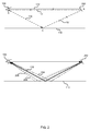
- FIG. 2 is a schematic diagram of light rays emitted and received by a time of flight system with and without multipath reflections;
- FIG. 3 is a schematic diagram of generating an accurate depth values from amplitude and phase measurements of a time of flight camera
- FIG. 4 is a flow diagram of using a general multipath computation to fill values of a look up table for use in a process such as the process of FIG. 3 ;
- FIG. 5 is a schematic diagram of a general multipath computation component for use in a method such as that of FIG. 4 ;
- FIG. 6 is a schematic diagram of a backscattering and of processes to compute a depth value from the backscattering
- FIG. 7 is a schematic diagram of an example phase modulation time of flight depth camera
- FIG. 8 illustrates an exemplary computing-based device in which embodiments of accurate depth computation taking into account three or more time of flight camera ray paths per pixel is implemented.
- time of flight system used indoors in an environment such as a living room with a shiny, specular floor. However, this is not essential.
- the time of flight system described herein may be used in other environments including outdoor environments.
- Phase modulation time of flight depth cameras can generate depth maps in near real time and are therefore suitable for tracking movements of humans, for example, gestures used for interacting with electronic devices, e.g. game consoles, televisions and other electronic devices.
- phase modulation time of flight depth cameras may be used for range measurement, automotive applications e.g. parking sensors and collision avoidance systems and other applications where accurate distances to objects are measured.
- the terms “camera” and “depth camera” are used herein interchangeably with “phase modulation time of flight camera”.
- a depth map is an image where each pixel comprises a depth value indicating a distance from the camera to a surface in a scene depicted in the image. As mentioned in the background section, multipath interference leads to significant errors in depth maps from time of flight systems.
- FIG. 1 is a schematic diagram of generating accurate depth maps of an indoor scene using a phase modulation time of flight depth camera.
- a time of flight system 106 comprising one or more light sources and a camera is mounted on the wall of a living room 108 having a shiny floor 110 .
- Light emitted by the time of flight sensor may travel along light ray 112 and reflect back off the floor along light ray 114 into the camera. In this case no multipath interference occurs. However light sent out along ray 116 may reflect off the wall and continue along ray 115 ; this light then reflects off the shiny floor 110 and continues along ray 114 back to the sensor.
- the signal at the camera comprises data from the direct path (light rays 112 and 114 ) mixed with data from a secondary path (light rays 116 , 115 , and 114 ).
- the data from the direct path ( 112 , 114 ) gives an accurate measurement of the depth from the camera to the floor.
- the data from the secondary path ( 116 , 115 , and 114 ) does not because the distance the light ray travels is not an indicator of the distance between the camera and the floor.
- Many more possible light ray paths may produce components of the signal at the camera. This is described in more detail with reference to FIG. 2 below.
- the time of flight system 106 comprises, or is in communication with, a depth map component 100 .
- the depth map component 100 is computer implemented using software and/or hardware. It may be integral with a camera of the time of flight system 106 .
- the depth map component 100 is implemented at an entity in communication (over any suitable communications network) with the time of flight system 106 .
- a game system 128 a natural user interface 124 apparatus, a gesture recognition 130 apparatus or other apparatus which takes depth maps as input.
- the depth map component 100 may be implemented at a computing device in the cloud in some examples.
- the time of flight system 106 may send measurement data to the time of flight system over a communications network such as the internet or any other wired and/or wireless communications network.
- the time of flight sensor is static because it is fixed to a wall of a living room.
- the time of flight sensor it is also possible for the time of flight sensor to be mounted on a moving object such as a person, vehicle, robot or other moving entity.
- the depth map component 100 comprises a multi-path correction look up table 102 which is stored in memory at the depth map component 100 .
- the look up table comprises a plurality of indices each having an associated (corrected) depth value and optionally also a corresponding confidence value.
- the indices may be numerical values such as integers.
- the depth values may be scalar values in units of distance such as centimeters or other distance units.
- a depth value may be replaced by an error code in some table entries where no reliable depth value can be measured by the time of flight system.
- the look up table may be stored as a list, array or using any suitable format.
- the depth values in the look up table are pre-computed corrected depth values.
- a corrected depth value is a depth of a surface from the camera having been calculated by taking into account at least three possible light ray paths between the camera and a surface in the scene.
- the corrected depth values are calculated using a measurement function which takes into account general multipath.
- a measurement function describes how measurements from a sensor (time of flight camera in this case) relate to the quantity being measured (distances of surfaces from the camera in this case). This gives improved accuracy as compared with previous approaches which have only allowed for two-path multipath.
- General multipath takes into account a potentially infinite number of possible light ray paths between the camera and a surface in the scene, including where reflection from Lambertian surfaces is involved. More detail about how the corrected depth values are calculated is given below with reference to FIGS. 4 and 5 .
- the depth map component 108 comprises a depth map computation logic 104 .
- This logic 104 is computer implemented using software and/or hardware. It reads data from the look up table 102 and populates a depth map using the data. As a result accurate depth maps 122 are output from the depth map component 108 .
- the accurate depth maps may be computed in real time, for example, at a frame rate of the camera at the time of flight system 106 . This is because the corrected depth values may be computed off-line and so the time taken to compute the corrected depth values does not impact the time taken to compute the depth map.
- the size of the look up table is very large and this also influences computational resources and memory requirements at the depth map component 108 . This means that even when using a look up table it is difficult to achieve real time operation.
- the measurement data from the time of flight system 106 may be six dimensional or higher dimensional. In that case the dimensionality of the look up table is also extremely high.
- a canonical representation may be used to reduce the number of dimensions of the look up table as described in detail in U.S. patent application Ser. No. 13/917,974 filed on 14 Jun. 2013 entitled “Depth map correction using look up tables”.
- This canonical representation and how it may be used in the examples described herein is also summarized later in this document.
- the examples described below use this type of canonical representation process. However, it is not essential to use the canonical representation.
- the examples below may be modified to omit the use of the canonical representation where real time operation is not required and/or where parallel processing units are used.
- FIG. 1 shows two schematic depth reconstructions of the base of the sitting room wall opposite the time of flight system 106 , where the wall joins the floor.
- a corrected depth reconstruction 118 shows a coherent wall and floor.
- a depth reconstruction 120 shows part of the wall coherently but the floor is corrupted, especially near the join between the wall and floor and at the edges of the floor. These are regions where multipath interference is a particular problem.
- the schematic depth reconstructions 118 , 120 are based on empirically derived depth reconstructions from a working time of flight system implementing the methods described herein.
- FIG. 2 is a schematic diagram of light rays emitted and received by a time of flight system with and without multipath reflections.
- a time of flight system 106 emits light ray 112 which travels parallel with the floor 110 , reflects off surface 200 and returns to the time of flight sensor 106 along path 114 .
- the path 112 , 114 has a length twice that of the distance of the surface from the time of flight system 106 .
- the pixel at the time of flight sensor which receives light ray 114 may also receive light from ray 116 as a result of light ray 116 reflecting off of the floor 110 at point C, continuing on light ray 201 to the surface at point B, and then returning to the surface along light ray 114 .
- a signal at the sensor which gives rise to the pixel is then made up of a component from a first path ( 112 , 114 ) and a component from a second path ( 116 , 201 , 114 ).
- Previous correction systems have attempted to correct for interference in this two path case. However, there are a potentially infinite number of possible paths 116 , 204 , 206 , 208 , that can give rise to interference as illustrated in the lower half of FIG.
- FIG. 3 is a flow diagram of an example process at depth map component 100 .
- a canonical representation is used to speed up processing as mentioned above.
- Amplitude and phase measurements are received 300 from a time of flight sensor for a specified pixel (or other image element). These may comprise a continuous amplitude value comprising a real scalar value and a continuous phase value expressed as a complex number for each of a plurality of modulation frequencies. That is, the time of flight sensor may be arranged to emit light at each of a plurality of different modulation frequencies.
- the measurement data, comprising the amplitude and phase values has a number of dimensions. For example, where three modulation frequencies are used the number of dimensions may be six as there is an amplitude and a phase value for each modulation frequency.
- the lower dimensional continuous measurement values 304 are input to a discretization logic 306 which converts the measurement values into discrete values, for example, using a binning process, and calculates a single index 308 into a look up table 316 from the discrete values.
- a read process 310 uses the single index to read a depth value from the look up table 316 .
- the look up table 316 comprises a column of indices and a column of associated depth values which have been calculated to take into account generalized multipath interference. For example, where three or more possible light ray paths between the time of flight camera and a surface are taken into account.
- the depth value 312 that is read from the look up table 316 is stored in a depth map 314 at a location corresponding to the location of the pixel in the image.
- the process of FIG. 3 repeats for more pixels of the image so that the depth map fills up.
- the process of FIG. 3 may be implemented in parallel using a parallel computing unit in order to speed up calculation of the depth map 314 . However this is not essential. For example, the process of FIG. 3 has been found to take less than 30 milliseconds per frame, for images comprising over 200,000 pixels, using a standard CPU.
- the resulting depth map 314 comprises depth values more accurate than previously possible in a very efficient manner.
- the accurate depth values are read from the look up table without the need for any additional correction step unlike previous approaches.
- the process of FIG. 3 may be modified by omitting the canonical representation mapping logic 302 .
- the size of the look up table is increased because the size of the look up table is exponential with respect to the number of dimensions of the measurement values. The memory requirements to store the look up table are thereby increased.
- FIG. 4 is a flow diagram of a method of calculating and filling data in the look up table of FIG. 3 .
- This process is computer implemented using software and/or hardware. It may be carried out at a look up table construction logic 716 which may be provided at the time of flight system or at another computing device.
- a range of indices is selected for the look up table. For example, by specifying a range of indices corresponding to measurement values that in turn correspond to distances that the time of flight camera is to operate in. A plurality of indices within that range are selected. The number of indices selected and the intervals between the corresponding distance values may be chosen depending on factors such as the application domain, the available memory resources, the available computing resources and other factors.
- the process of FIG. 4 is carried out for each selected index to compute a depth value, and optionally a certainty of the depth value, to write to the look up table.
- the example of FIG. 4 uses a canonical representation. However, this is not essential as mentioned above.
- the index is mapped to 4D discrete measurement values 404 (corresponding to a single pixel or other image element) using a mapping process 402 .
- the 4D discrete measurement values (comprising amplitude and phase values) are mapped to 4D continuous measurements 408 using a mapping to analog measurement component 406 .
- the 4D continuous measurements 408 are mapped to 6D normalized measurements 412 using a mapping to 6D component 410 .
- the 6D normalized measurements 412 are input to a general multipath computation 414 which computes backscattering values 416 .
- the general multipath computation 414 comprises a measurement function which describes how the 6D measurements relate to a potentially infinite number of light ray paths between the time of flight camera and a surface in the scene being observed.
- the backscattering values are weights indicating how much contribution each potential light ray path makes to the amplitude and phase values observed at the pixel.
- the backscattering values may be computed by searching different combinations of possible backscattering values to find a combination which best describes the measurement values. This search may be done using an optimization process or a heuristic process such as a greedy method as described in more detail with reference to FIG. 5 .
- the process calculates a single depth value to write to the look up table. This is done using depth computation component 418 which may access a noise model 424 .
- the depth computation component 418 may calculate a depth value and optionally a certainty of the depth value. Where no sensible depth value is calculated an error may be returned.
- the process writes the depth value, or the error, to the lookup table field 422 corresponding to the single index 400 .
- the process may also write the certainty of the depth value to the look up table.
- FIG. 5 is a schematic diagram of the general multipath computation component 414 of FIG. 4 in more detail.
- This component calculates a combination of values in a backscattering vector which best describe given measurement values, given that the backscattering vector is related to the measurements via a specified measurement function for time of flight systems.
- This is not straightforward because there are a potentially infinite number of light ray paths creating multipath interference as described above with reference to FIG. 2 , and these light ray paths may have different weights.
- the backscattering vector is compressible, that is, it has redundancy.
- the backscattering vector is sparse in that many of the values in the backscattering vector are zero. This is because many of the possible light ray paths do not contribute to the multipath interference at a given pixel of the time of flight camera.
- an optimization engine 500 integral with the general multipath computation unit 414 calculates a minimum of an L 1 norm of the backscattering vector subject to time of flight measurement data 412 applied to the measurement function and optionally taking into account noise. This gives a backscattering vector 416 .
- An L 1 norm is the sum of the absolute values of a vector. Any suitable optimization engine may be used.
- greedy methods are used to find a best combination of values in the backscattering vector.
- a greedy method is one which searches for a best value for single ones of the backscattering vector entries in turn and allocates that value without taking into account future entries of the vector which may influence the current allocation.
- matching pursuit may be used which involves finding the “best matching” projections of multidimensional data onto an over-complete dictionary of functions.
- a Hilbert space signal is represented as a weighted sum of functions (called atoms) from the dictionary. Given a fixed dictionary, a matching pursuit process first finds an atom from the dictionary that has a biggest inner product with the signal. The process then subtracts from the signal the contribution due to that atom, and repeat the process until the signal is satisfactorily decomposed.
- the signal is the measurement values from the time of flight sensor for a given pixel; the atoms in the dictionary are possible entries of the backscattering vector.
- the matching pursuit process finds a set of backscattering vector entries that best project onto the measurement vector.
- measurement values v from a time of flight camera for a given pixel and at a modulation frequency k are equal to the sum, over a plurality n of distance bins (discrete distance ranges formed by dividing a range of distances from the time of flight camera into bins), of a backscattering vector entry x j for the bin times a function.
- This function is a complex exponential of the ratio of the distance of the bin from the time of flight camera d j , to the half-wavelength of light ⁇ k emitted by the time of flight system at the modulation frequency k.
- the vector x is referred to as the backscattering. It has one element for each distance bin. An entry in the backscattering vector is related to the strength of the reflection at the bucketed distance range corresponding to the position of the entry in the vector.
- the matrix ⁇ contains complex numbers as the time of flight camera outputs measurement data comprising complex numbers representing the phase. The complex numbers are converted to real ones by stacking the real part of v on top of the complex part and denoting the 2m-dimsnsional result as v. Doing the same with ⁇ leads to a 2m ⁇ n real matrix given by
- L 1 norm is a sum of the absolute values of the backscattering vector. This process tries to find the sparsest backscattering vector x which yields the measurement vector v.
- noise in the measurement process is taken into account by including a noise term in the measurement function. Optimization, or greedy methods are then used to find the sparsest backscattering vector which yields the measurement values given a measurement function which takes into account noise.
- the noise may be taken to be Gaussian noise with zero mean and known covariance matrix C. This is one example only, other distributions may be used to represent noise.
- noise is taken into account by modifying the L 1 optimization to be an L 1 optimization with L 2 constraints as follows:
- Equation 2 x ⁇ 0 ⁇ x ⁇ 1 subject to ( ⁇ x ⁇ v) T C ⁇ 1 ( ⁇ x ⁇ v) ⁇ 2 ⁇ v ⁇ 2 (referred to as equation 2 herein) where the symbol ⁇ is a parameter controlling the amount of noise. This may be solved with general convex programming solvers.
- noise is taken into account by modifying the L 1 optimization to be an L 1 optimization with L 1 constraints as follows: min x ⁇ 0 ⁇ x ⁇ 1 subject to ⁇ C ⁇ 1/2 ( ⁇ x ⁇ v ) ⁇ 1 ⁇ v ⁇ 1
- the backscattering vector is illustrated in graphical form 504 with depth along the x axis and the magnitude of the backscattering vector entries on the y axis.
- backscattering vector entries also referred to as backscattering values
- a depth computation component 418 calculates a depth value 420 from the backscattering values 416 . This is now explained with reference to FIG. 6 .
- the backscattering values 416 may be represented as a graph 504 in one example.
- the depth computation component 418 selects 600 the first non-zero entry of the backscattering vector and uses this to calculate the depth value. That is, the distance bin corresponding to this entry of the backscattering vector is assumed to be the distance range at which there is a surface giving rise to the measured light. It is used to calculate the distance to the surface from the time of flight camera. This gives a depth value 602 .
- the first non-zero entry of the backscattering vector corresponds to the shortest light ray path which contributes to signal at the relevant pixel. This is because the entries in the backscattering vector are ordered in the order of the distance bins.
- the depth computation component 418 takes into account a noise model 424 .
- the depth computation component may use a noise model to compute 604 a probability that an entry of the backscattering vector is a result of noise.
- a threshold may be applied 606 to filter out entries of the backscattering vector which are likely to be due to noise.
- the depth computation component may select 608 one of the remaining non-zero entries of the backscattering vector on the basis of the probabilities that those entries are due to noise. For example, an entry which is least likely to be due to noise may be selected. In some examples, if all the non-zero entries are likely to be due to noise, an error may be returned. For example, the pixel is declared invalid.
- Combinations of the processes of FIG. 6 may be used. For example, finding a backscattering vector entry on the basis of both: its corresponding distance; and on the basis of a probability the vector entry is not due to noise.
- the distance is from the time of flight system to a surface in a scene.
- one of the elements is redundant, in that it is completely determined by the other elements. Hence, this element can be removed without losing information.
- the component is complex, meaning that we have removed two real dimensions, hence enabling the promised dimension reduction from 2m to 2m ⁇ 2.
- a method at the depth map computation logic 104 comprises: receiving, at a processor, time of flight depth camera amplitude and phase measurements depicting surfaces in a scene, the measurements being received at a frame rate of the time of flight camera; computing indices of a look up table from the measurements; using the indices to read corrected depth values from the look up table, the corrected values being depths of surfaces from the camera having been calculated so as to reduce the effects of general multipath interference; and using the corrected depth values to form a depth map in a time at or below the frame rate of the time of flight camera.
- FIG. 7 is a schematic diagram of a phase modulation time of flight depth camera.
- a phase modulation time of flight depth camera 700 may comprise a source of transmitted light 702 .
- the source of transmitted light is an incoherent light source.
- the source of transmitted light is a coherent light source.
- An example of an appropriate light source is a near infra-red laser or a light emitting diode (LED) however another appropriate light source may be used.
- the transmitted light may be modulated at one or more modulation frequencies.
- the modulation frequencies may be RF frequencies in the range kHz-GHz, for example the modulation frequencies may be in the MHz range.
- a phase modulation time of flight depth camera may further comprise an image sensor 704 that receives light reflected from objects within a scene.
- the image sensor 704 may comprise a CCD sensor, a CMOS sensor, for example a Photonic Mixer Device (PMD) sensor or other appropriate sensor which may be arranged to detect light reflected from surfaces of objects, people or other entities within the camera range.
- PMD Photonic Mixer Device
- the camera may further comprise an optical system 706 that is arranged to gather and focus light (ambient light and light emitted by the source 702 and reflected) from the environment on to the image sensor 704 .
- the optical system may comprise an optical band pass filter, which may enable only light of the same wavelength as the light source to be received by the sensor. The use of an optical band pass filter may help to suppress background light.
- the camera may also comprise driver electronics 708 which control both the light source and an image sensor, for example, to enable highly accurate phase difference measurements to be made.
- the camera may comprise computation logic 710 .
- computation logic may be arranged to execute the methods described herein with reference to one or more of FIG. 4 , FIG. 5 and FIG. 6 .
- the described method of computing the look up table values may be executed as a one-time process during camera testing and calibration.
- Computation logic may further comprise integrated depth map computation logic 712 , optional look up table construction logic 716 and a lookup table 714 stored at a memory.
- depth map computation logic 712 may be arranged to estimate a distance of an object from the difference in phase between light transmitted from the light source and the light received at the receiver.
- the received light has undergone at least two path reflection e.g. multipath reflection.
- the lookup table 714 may store an association between measured amplitudes and phases (converted into single valued indexes) and corrected depth values as described above.
- look up table construction logic 716 may be used to populate lookup table 714 as described above with reference to FIG. 4 . However, it is not essential to implement the look up table construction logic 716 at the camera.
- the computation logic 710 may be located external to the camera on another device e.g. a game system, personal computer, mobile device or other computing device.
- the functionality of one or more of the components of the computation logic 710 may be performed, at least in part, by one or more hardware logic components.
- illustrative types of hardware logic components include Field-programmable Gate Arrays (FPGAs), Program-specific Integrated Circuits (ASICs), Program-specific Standard Products (ASSPs), System-on-a-chip systems (SOCs), Complex Programmable Logic Devices (CPLDs), Graphics Processing Units (GPUs).
- FIG. 8 illustrates various components of an exemplary computing-based device 800 which may be implemented as any form of a computing and/or electronic device, and in which embodiments of any of the methods described herein may be implemented.
- Computing-based device 800 comprises one or more processors 802 which may be microprocessors, controllers or any other suitable type of processors for processing computer executable instructions to control the operation of the device in order to do any of: compute general multipath corrected depth values and store those values in a look up table, compute an accurate depth measurement from empirical time of flight measurement values.
- the processors 802 may include one or more fixed function blocks (also referred to as accelerators) which implement a part of the method of depth computation or look up table creation using hardware (rather than software or firmware). For example, computation logic for computing depth maps may be implemented in hardware.
- Platform software comprising an operating system 804 or any other suitable platform software may be provided at the computing-based device to enable application software 806 to be executed on the device.
- computing-based device 800 may further comprise computation logic 808 .
- Computation logic 808 may further comprise integrated depth map computation logic 810 , and a stored depth correction lookup table 812 which may be arranged to operate as described above with reference to FIG. 3 .
- depth map computation logic 810 may be arranged to estimate a distance of an object from the difference in phase between light transmitted from the light source and the light received at the receiver.
- the received light has undergone general multipath reflection involving two or more light ray paths in addition to a light ray path with no interference.
- the computation logic 808 is arranged to compute accurate depth values for filling the look up table as described above with reference to FIG. 4 .
- Computer-readable media may include, for example, computer storage media such as memory 816 and communications media.
- Computer storage media, such as memory 816 includes volatile and non-volatile, removable and non-removable media implemented in any method or technology for storage of information such as computer readable instructions, data structures, program modules or other data.
- Computer storage media includes, but is not limited to, RAM, ROM, EPROM, EEPROM, flash memory or other memory technology, CD-ROM, digital versatile disks (DVD) or other optical storage, magnetic cassettes, magnetic tape, magnetic disk storage or other magnetic storage devices, or any other non-transmission medium that can be used to store information for access by a computing device.
- communication media may embody computer readable instructions, data structures, program modules, or other data in a modulated data signal, such as a carrier wave, or other transport mechanism.
- computer storage media does not include communication media. Therefore, a computer storage medium should not be interpreted to be a propagating signal per se. Propagated signals may be present in a computer storage media, but propagated signals per se are not examples of computer storage media.
- the computer storage media memory 816
- the storage may be distributed or located remotely and accessed via a network or other communication link (e.g. using communication interface 808 ).
- the computing-based device 800 also comprises an input/output controller 820 arranged to output display information to a display device 824 which may be separate from or integral to the computing-based device 800 .
- the display information may provide a graphical user interface.
- the input/output controller 820 is also arranged to receive and process input from one or more devices, such as a user input device 822 (e.g. a mouse, keyboard, camera, microphone or other sensor).
- the user input device 822 may detect voice input, user gestures or other user actions and may provide a natural user interface (NUI). This user input may be used to generate depth maps as described above.
- the display device 824 may also act as the user input device 822 if it is a touch sensitive display device.
- the input/output controller 820 may also output data to devices other than the display device, e.g. a locally connected printing device (not shown in FIG. 8 ).
- NUI technology which enables a user to interact with the computing-based device in a natural manner, free from artificial constraints imposed by input devices such as mice, keyboards, remote controls and the like.
- NUI technology examples include but are not limited to those relying on voice and/or speech recognition, touch and/or stylus recognition (touch sensitive displays), gesture recognition both on screen and adjacent to the screen, air gestures, head and eye tracking, voice and speech, vision, touch, gestures, and machine intelligence.
- NUI technology examples include intention and goal understanding systems, motion gesture detection systems using depth cameras (such as stereoscopic camera systems, infrared camera systems, RGB camera systems and combinations of these), motion gesture detection using accelerometers/gyroscopes, facial recognition, 3D displays, head, eye and gaze tracking, immersive augmented reality and virtual reality systems and technologies for sensing brain activity using electric field sensing electrodes (EEG and related methods).
- depth cameras such as stereoscopic camera systems, infrared camera systems, RGB camera systems and combinations of these
- motion gesture detection using accelerometers/gyroscopes such as stereoscopic camera systems, infrared camera systems, RGB camera systems and combinations of these
- motion gesture detection using accelerometers/gyroscopes such as stereoscopic camera systems, infrared camera systems, RGB camera systems and combinations of these
- accelerometers/gyroscopes such as stereoscopic camera systems, infrared camera systems, RGB camera systems and combinations of these
- accelerometers/gyroscopes such
- computer or ‘computing-based device’ is used herein to refer to any device with processing capability such that it can execute instructions.
- processors including smart phones
- tablet computers or tablet computers
- set-top boxes media players
- games consoles personal digital assistants and many other devices.
- the methods described herein may be performed by software in machine readable form on a tangible storage medium e.g. in the form of a computer program comprising computer program code means adapted to perform all the steps of any of the methods described herein when the program is run on a computer and where the computer program may be embodied on a computer readable medium.
- tangible storage media include computer storage devices comprising computer-readable media such as disks, thumb drives, memory etc. and do not include propagated signals. Propagated signals may be present in a tangible storage media, but propagated signals per se are not examples of tangible storage media.
- the software can be suitable for execution on a parallel processor or a serial processor such that the method steps may be carried out in any suitable order, or simultaneously.
- a remote computer may store an example of the process described as software.
- a local or terminal computer may access the remote computer and download a part or all of the software to run the program.
- the local computer may download pieces of the software as needed, or execute some software instructions at the local terminal and some at the remote computer (or computer network).
- a dedicated circuit such as a DSP, programmable logic array, or the like.
Abstract
Description
minx≧0 ∥x∥ 1 subject to v=Φx
minx≧01T x subject to v=φx (referred to below as equation 1)
minx≦0 ∥x∥ 1 subject to ∥C −1/2(Φx−v)∥1 ≦ε∥v∥ 1
C(v;s,Δ)=F s,Δ v
further, let us take dlj=j (i.e. spacing of 1 cm), and let j run from −∞ to ∞. In this case, it is easy to see that C(Φ∞; s, Δ) ∝Φ∞ for any Δε
ρ(k)(v)≡C(v;s=∥v∥ −1,Δ=λk(∠v k/2π))
where ∠vk denotes the phase of vk, taken to lie in [0,2m). It is easy to see that ρ(k) has the following properties:
Claims (19)
Priority Applications (4)
| Application Number | Priority Date | Filing Date | Title |
|---|---|---|---|
| US14/148,184 US9542749B2 (en) | 2014-01-06 | 2014-01-06 | Fast general multipath correction in time-of-flight imaging |
| CN201480072366.8A CN105899969B (en) | 2014-01-06 | 2014-12-12 | Universal-purpose quick multi-path correction in flight time imaging |
| EP14828387.2A EP3092509B1 (en) | 2014-01-06 | 2014-12-12 | Fast general multipath correction in time-of-flight imaging |
| PCT/US2014/069868 WO2015102847A1 (en) | 2014-01-06 | 2014-12-12 | Fast general multipath correction in time-of-flight imaging |
Applications Claiming Priority (1)
| Application Number | Priority Date | Filing Date | Title |
|---|---|---|---|
| US14/148,184 US9542749B2 (en) | 2014-01-06 | 2014-01-06 | Fast general multipath correction in time-of-flight imaging |
Publications (2)
| Publication Number | Publication Date |
|---|---|
| US20150193938A1 US20150193938A1 (en) | 2015-07-09 |
| US9542749B2 true US9542749B2 (en) | 2017-01-10 |
Family
ID=52392202
Family Applications (1)
| Application Number | Title | Priority Date | Filing Date |
|---|---|---|---|
| US14/148,184 Active 2034-03-21 US9542749B2 (en) | 2014-01-06 | 2014-01-06 | Fast general multipath correction in time-of-flight imaging |
Country Status (4)
| Country | Link |
|---|---|
| US (1) | US9542749B2 (en) |
| EP (1) | EP3092509B1 (en) |
| CN (1) | CN105899969B (en) |
| WO (1) | WO2015102847A1 (en) |
Cited By (16)
| Publication number | Priority date | Publication date | Assignee | Title |
|---|---|---|---|---|
| US10178370B2 (en) | 2016-12-19 | 2019-01-08 | Sony Corporation | Using multiple cameras to stitch a consolidated 3D depth map |
| US10181089B2 (en) | 2016-12-19 | 2019-01-15 | Sony Corporation | Using pattern recognition to reduce noise in a 3D map |
| US10215856B1 (en) | 2017-11-27 | 2019-02-26 | Microsoft Technology Licensing, Llc | Time of flight camera |
| US10451714B2 (en) | 2016-12-06 | 2019-10-22 | Sony Corporation | Optical micromesh for computerized devices |
| US10484667B2 (en) | 2017-10-31 | 2019-11-19 | Sony Corporation | Generating 3D depth map using parallax |
| US10495735B2 (en) | 2017-02-14 | 2019-12-03 | Sony Corporation | Using micro mirrors to improve the field of view of a 3D depth map |
| US10536684B2 (en) | 2016-12-07 | 2020-01-14 | Sony Corporation | Color noise reduction in 3D depth map |
| US10549186B2 (en) | 2018-06-26 | 2020-02-04 | Sony Interactive Entertainment Inc. | Multipoint SLAM capture |
| US10795021B2 (en) * | 2013-03-20 | 2020-10-06 | Iee International Electronics & Engineering S.A. | Distance determination method |
| US10795022B2 (en) | 2017-03-02 | 2020-10-06 | Sony Corporation | 3D depth map |
| US10901087B2 (en) | 2018-01-15 | 2021-01-26 | Microsoft Technology Licensing, Llc | Time of flight camera |
| US10914817B2 (en) | 2019-03-29 | 2021-02-09 | Rockwell Automation Technologies, Inc. | Multipath interference error correction in a time of flight sensor |
| US10928489B2 (en) | 2017-04-06 | 2021-02-23 | Microsoft Technology Licensing, Llc | Time of flight camera |
| US10935641B2 (en) * | 2017-10-30 | 2021-03-02 | Texas Instruments Incorporated | Phase noise shaping in a distance measurement system |
| US10979687B2 (en) | 2017-04-03 | 2021-04-13 | Sony Corporation | Using super imposition to render a 3D depth map |
| US11870699B1 (en) | 2022-06-27 | 2024-01-09 | Ottopia Technologies Ltd. | Techniques for multi-channel network congestion control |
Families Citing this family (47)
| Publication number | Priority date | Publication date | Assignee | Title |
|---|---|---|---|---|
| US9753131B2 (en) * | 2013-10-09 | 2017-09-05 | Massachusetts Institute Of Technology | Motion tracking via body radio reflections |
| EP2966475B1 (en) * | 2014-07-09 | 2016-05-25 | Softkinetic Sensors N.V. | A method for binning time-of-flight data |
| US9581696B2 (en) * | 2014-12-22 | 2017-02-28 | Google Inc. | Image sensor and light source driver integrated in a same semiconductor package |
| US9948920B2 (en) | 2015-02-27 | 2018-04-17 | Qualcomm Incorporated | Systems and methods for error correction in structured light |
| US10068338B2 (en) | 2015-03-12 | 2018-09-04 | Qualcomm Incorporated | Active sensing spatial resolution improvement through multiple receivers and code reuse |
| US10062201B2 (en) | 2015-04-21 | 2018-08-28 | Microsoft Technology Licensing, Llc | Time-of-flight simulation of multipath light phenomena |
| TWI676281B (en) | 2015-07-23 | 2019-11-01 | 光澄科技股份有限公司 | Optical sensor and method for fabricating thereof |
| US10761599B2 (en) | 2015-08-04 | 2020-09-01 | Artilux, Inc. | Eye gesture tracking |
| TWI723890B (en) | 2015-08-04 | 2021-04-01 | 光澄科技股份有限公司 | Method for fabricating image sensor array |
| US10707260B2 (en) | 2015-08-04 | 2020-07-07 | Artilux, Inc. | Circuit for operating a multi-gate VIS/IR photodiode |
| US10861888B2 (en) | 2015-08-04 | 2020-12-08 | Artilux, Inc. | Silicon germanium imager with photodiode in trench |
| US9635339B2 (en) * | 2015-08-14 | 2017-04-25 | Qualcomm Incorporated | Memory-efficient coded light error correction |
| DE102015011246B4 (en) | 2015-08-25 | 2023-06-29 | Audi Ag | Localization of signal sources using motor vehicles |
| WO2017035447A1 (en) | 2015-08-27 | 2017-03-02 | Artilux Corporation | Wide spectrum optical sensor |
| US9846943B2 (en) | 2015-08-31 | 2017-12-19 | Qualcomm Incorporated | Code domain power control for structured light |
| US10418407B2 (en) | 2015-11-06 | 2019-09-17 | Artilux, Inc. | High-speed light sensing apparatus III |
| US10739443B2 (en) | 2015-11-06 | 2020-08-11 | Artilux, Inc. | High-speed light sensing apparatus II |
| US10741598B2 (en) | 2015-11-06 | 2020-08-11 | Atrilux, Inc. | High-speed light sensing apparatus II |
| US10254389B2 (en) | 2015-11-06 | 2019-04-09 | Artilux Corporation | High-speed light sensing apparatus |
| US10886309B2 (en) | 2015-11-06 | 2021-01-05 | Artilux, Inc. | High-speed light sensing apparatus II |
| US9760837B1 (en) | 2016-03-13 | 2017-09-12 | Microsoft Technology Licensing, Llc | Depth from time-of-flight using machine learning |
| US10598783B2 (en) | 2016-07-07 | 2020-03-24 | Microsoft Technology Licensing, Llc | Multi-frequency unwrapping |
| KR102561099B1 (en) * | 2016-09-23 | 2023-07-28 | 삼성전자주식회사 | ToF(time of flight) capturing apparatus and method for reducing of depth distortion caused by multiple reflection thereof |
| US10762651B2 (en) | 2016-09-30 | 2020-09-01 | Magic Leap, Inc. | Real time calibration for time-of-flight depth measurement |
| US10242454B2 (en) * | 2017-01-25 | 2019-03-26 | Google Llc | System for depth data filtering based on amplitude energy values |
| DE102017205402A1 (en) * | 2017-03-30 | 2018-10-04 | Robert Bosch Gmbh | lidar |
| US10255105B2 (en) * | 2017-04-11 | 2019-04-09 | Imagination Technologies Limited | Parallel computing architecture for use with a non-greedy scheduling algorithm |
| JP2019015706A (en) * | 2017-07-11 | 2019-01-31 | ソニーセミコンダクタソリューションズ株式会社 | Imaging device and monitoring device |
| US10989803B1 (en) | 2017-08-21 | 2021-04-27 | Massachusetts Institute Of Technology | Security protocol for motion tracking systems |
| US11105928B2 (en) | 2018-02-23 | 2021-08-31 | Artilux, Inc. | Light-sensing apparatus and light-sensing method thereof |
| TWI762768B (en) | 2018-02-23 | 2022-05-01 | 美商光程研創股份有限公司 | Photo-detecting apparatus |
| CN112236686B (en) | 2018-04-08 | 2022-01-07 | 奥特逻科公司 | Optical detection device |
| TWI795562B (en) | 2018-05-07 | 2023-03-11 | 美商光程研創股份有限公司 | Avalanche photo-transistor |
| US10969877B2 (en) | 2018-05-08 | 2021-04-06 | Artilux, Inc. | Display apparatus |
| CN112313541A (en) * | 2018-05-09 | 2021-02-02 | 索尼半导体解决方案公司 | Apparatus and method |
| CN109756662B (en) * | 2018-11-14 | 2023-06-13 | 深圳大学 | Depth information correction method and depth information correction device based on DLL (delay locked loop) |
| US11393115B2 (en) * | 2018-11-27 | 2022-07-19 | Infineon Technologies Ag | Filtering continuous-wave time-of-flight measurements, based on coded modulation images |
| CN109738881B (en) * | 2019-01-11 | 2023-08-08 | 歌尔光学科技有限公司 | Calibration method and device of time-of-flight depth module and readable storage medium |
| US20200249348A1 (en) * | 2019-02-04 | 2020-08-06 | Analog Devices, Inc. | Resolving multi-path corruption of time-of-flight depth images |
| CN110133676B (en) * | 2019-06-21 | 2021-06-11 | 浙江舜宇光学有限公司 | Depth detection system and method |
| CN112532858A (en) * | 2019-09-18 | 2021-03-19 | 华为技术有限公司 | Image processing method, image acquisition method and related device |
| CN113009508B (en) * | 2019-12-20 | 2023-11-07 | 舜宇光学(浙江)研究院有限公司 | Multipath interference correction method for TOF module, system and electronic equipment thereof |
| JP2021117036A (en) * | 2020-01-23 | 2021-08-10 | 株式会社日立エルジーデータストレージ | Measurement value correction method of range-finding device |
| CN111710024A (en) * | 2020-03-23 | 2020-09-25 | 上海数迹智能科技有限公司 | Method for eliminating multipath interference in ToF camera based on multi-frequency and multi-illumination |
| CN113298778B (en) * | 2021-05-21 | 2023-04-07 | 奥比中光科技集团股份有限公司 | Depth calculation method and system based on flight time and storage medium |
| DE102022131218A1 (en) | 2021-11-26 | 2023-06-01 | Ifm Electronic Gmbh | Camera system with cross-talk compensation |
| CN113920254B (en) * | 2021-12-15 | 2022-03-22 | 深圳市其域创新科技有限公司 | Monocular RGB (Red Green blue) -based indoor three-dimensional reconstruction method and system thereof |
Citations (14)
| Publication number | Priority date | Publication date | Assignee | Title |
|---|---|---|---|---|
| US5930383A (en) | 1996-09-24 | 1999-07-27 | Netzer; Yishay | Depth sensing camera systems and methods |
| US6445491B2 (en) * | 1999-01-29 | 2002-09-03 | Irma America, Inc. | Method and apparatus for optical sectioning and imaging using time-gated parametric image amplification |
| US7312879B2 (en) | 2005-08-23 | 2007-12-25 | University Of Washington | Distance determination in a scanned beam image capture device |
| US20090322745A1 (en) * | 2006-09-21 | 2009-12-31 | Thomson Licensing | Method and System for Three-Dimensional Model Acquisition |
| US20110176709A1 (en) | 2010-01-21 | 2011-07-21 | Samsung Electronics Co., Ltd. | Method and apparatus for calculating a distance between an optical apparatus and an object |
| US20110310376A1 (en) | 2009-11-13 | 2011-12-22 | Samsung Electronics Co., Ltd. | Apparatus and method to correct image |
| US20120033045A1 (en) | 2010-07-23 | 2012-02-09 | Mesa Imaging Ag | Multi-Path Compensation Using Multiple Modulation Frequencies in Time of Flight Sensor |
| US20120081360A1 (en) * | 2010-10-05 | 2012-04-05 | Empire Technology Development Llc | Generation of Depth Data Based on Spatial Light Pattern |
| US20130026384A1 (en) * | 2011-07-27 | 2013-01-31 | Dongsoo Kim | Time-of-flight imaging systems |
| US20130050426A1 (en) | 2011-08-30 | 2013-02-28 | Microsoft Corporation | Method to extend laser depth map range |
| US20130093852A1 (en) * | 2011-10-12 | 2013-04-18 | Board Of Trustees Of The University Of Arkansas | Portable robotic device |
| US20130116977A1 (en) * | 2010-07-29 | 2013-05-09 | Waikatolink Ltd | Apparatus and method for measuring the distance and/or intensity characteristics of objects |
| WO2013121267A1 (en) | 2012-02-15 | 2013-08-22 | Mesa Imaging Ag | Time of flight camera with stripe illumination |
| US20140368613A1 (en) * | 2013-06-14 | 2014-12-18 | Microsoft Corporation | Depth map correction using lookup tables |
Family Cites Families (1)
| Publication number | Priority date | Publication date | Assignee | Title |
|---|---|---|---|---|
| CN102436657A (en) * | 2011-09-27 | 2012-05-02 | 夏东 | Active light depth measurement value modifying method based on application of the internet of things |
-
2014
- 2014-01-06 US US14/148,184 patent/US9542749B2/en active Active
- 2014-12-12 CN CN201480072366.8A patent/CN105899969B/en active Active
- 2014-12-12 WO PCT/US2014/069868 patent/WO2015102847A1/en active Application Filing
- 2014-12-12 EP EP14828387.2A patent/EP3092509B1/en active Active
Patent Citations (15)
| Publication number | Priority date | Publication date | Assignee | Title |
|---|---|---|---|---|
| US5930383A (en) | 1996-09-24 | 1999-07-27 | Netzer; Yishay | Depth sensing camera systems and methods |
| US6445491B2 (en) * | 1999-01-29 | 2002-09-03 | Irma America, Inc. | Method and apparatus for optical sectioning and imaging using time-gated parametric image amplification |
| US7312879B2 (en) | 2005-08-23 | 2007-12-25 | University Of Washington | Distance determination in a scanned beam image capture device |
| US20090322745A1 (en) * | 2006-09-21 | 2009-12-31 | Thomson Licensing | Method and System for Three-Dimensional Model Acquisition |
| US8339582B2 (en) | 2009-11-13 | 2012-12-25 | Samsung Electronics Co., Ltd. | Apparatus and method to correct image |
| US20110310376A1 (en) | 2009-11-13 | 2011-12-22 | Samsung Electronics Co., Ltd. | Apparatus and method to correct image |
| US20110176709A1 (en) | 2010-01-21 | 2011-07-21 | Samsung Electronics Co., Ltd. | Method and apparatus for calculating a distance between an optical apparatus and an object |
| US20120033045A1 (en) | 2010-07-23 | 2012-02-09 | Mesa Imaging Ag | Multi-Path Compensation Using Multiple Modulation Frequencies in Time of Flight Sensor |
| US20130116977A1 (en) * | 2010-07-29 | 2013-05-09 | Waikatolink Ltd | Apparatus and method for measuring the distance and/or intensity characteristics of objects |
| US20120081360A1 (en) * | 2010-10-05 | 2012-04-05 | Empire Technology Development Llc | Generation of Depth Data Based on Spatial Light Pattern |
| US20130026384A1 (en) * | 2011-07-27 | 2013-01-31 | Dongsoo Kim | Time-of-flight imaging systems |
| US20130050426A1 (en) | 2011-08-30 | 2013-02-28 | Microsoft Corporation | Method to extend laser depth map range |
| US20130093852A1 (en) * | 2011-10-12 | 2013-04-18 | Board Of Trustees Of The University Of Arkansas | Portable robotic device |
| WO2013121267A1 (en) | 2012-02-15 | 2013-08-22 | Mesa Imaging Ag | Time of flight camera with stripe illumination |
| US20140368613A1 (en) * | 2013-06-14 | 2014-12-18 | Microsoft Corporation | Depth map correction using lookup tables |
Non-Patent Citations (20)
| Title |
|---|
| "International Search Report & Written Opinion for PCT Application No. PCT/US2014/069868", Mailed Date: Apr. 7, 2015, 11 Pages. |
| A. Kirmani, A. Benedetti, and P.A. Chou. Spumic: Simultaneous phase un-wrapping and multipath interference cancellation in time-of-flight cameras using spectral methods. In IEEE International Conference on Multimedia and Expo (ICME), pp. 1-6, 2013. |
| Baraniuk, Richard G, "Compressive Sensing [Lecture Notes]", In IEEE Signal Processing Magazine, vol. 24, Issue 4, Jul. 2007, 4 pages. |
| Candes, Emmanuel J, "Compressive Sampling", In Proceedings of the International Congress of Mathematicians: Madrid, Aug. 22, 2006, 20 pages. |
| Candes, et al., "An Introduction to Compressive Sampling", In IEEE Signal Processing Magazine, vol. 25, Issue 2, Mar. 2008, 10 pages. |
| Candes, et al., "Decoding by Linear Programming", In IEEE Transactions on Information Theory, vol. 51, Issue 12, Dec. 2012, 13 pages. |
| Candes, et al., "Stable Signal Recovery from Incomplete and Inaccurate Measurements", In Communications on Pure and Applied Mathematics, vol. 59, Issue 8, Mar. 1, 2006, 17 pages. |
| D. Falie and V. Buzuloiu. Further investigations on ToF cameras distance errors and their corrections. In European Conference on Circuits and Systems for Communications (ECCSC), pp. 197-200, 2008. |
| Daubechies, et al., "Iteratively Reweighted Least Squares Minimization for Sparse Recovery", in Communications on Pure and Applied Mathematics, vol. 63, Issue 1, Oct. 19, 2009, 38 pages. |
| Donoho, David L, "Compressed Sensing", In IEEE Transactions on Information Theory, vol. 52, Issue 4, Apr. 2006, 18 pages. |
| Dorrington et al., "Separating True Range Measurements from Multi-Path and Scattering Interference in Commercial Range Cameras", In Proceedings of Three-Dimensional Imaging, Interaction, and Measurement, Jan. 27, 2011, 10 Pages. |
| Fuchs, Stefan, "Multipath Interference Compensation in Time-of-Flight Camera Images", In IEEE International Conference on Pattern Recognition, Aug. 23, 2010, 4 pages. |
| IPEA European Patent Office, International Preliminary Report on Patentability issued in Application No. PCT/US2014/069868, Mar. 15, 2016, WIPO, 8 pages. |
| IPEA European Patent Office, Second Written Opinion Issued in Application No. PCT/US2014/069868, Nov. 30, 2015, WIPO, 7 pages. |
| J. Han, L. Shao, D. Xu, and J. Shotton. Enhanced computer vision with Microsoft Kinect sensor: A review. IEEE Transactions on Cybernetics, 43(5): 1318-1334, 2013. |
| J. Wright, A. Y. Yang, A. Ganesh, S.S. Sastry, and Y. Ma. Robust face recognition via sparse representation. IEEE Transactions on Pattern Analysis and Machine Intelligence, 31(2):210-227, 2009. |
| Jimenez, et al., "Modelling and Correction of Multipath Interference in Time of Flight Cameras", In IEEE Conference on Computer Vision and Pattern Recognition, Jun. 16, 2012, 8 pages. |
| S. Fuchs, M. Suppa, and O. Hellwich. Compensation for multipath in ToF camera measurements supported by photometric calibration and environment integration. In Computer Vision Systems, pp. 31-41, 2013. |
| S.G. Mallat and Z. Zhang. Matching pursuits with time-frequency dictionaries. IEEE Transactions on Signal Processing, 41(12):3397-3415, 1993. |
| U.S. Appl. No. 13/917,974, Krupka,Eyal, "Depth Map Correction using Lookup Tables", filed Jun. 14, 2013. |
Cited By (18)
| Publication number | Priority date | Publication date | Assignee | Title |
|---|---|---|---|---|
| US10795021B2 (en) * | 2013-03-20 | 2020-10-06 | Iee International Electronics & Engineering S.A. | Distance determination method |
| US10451714B2 (en) | 2016-12-06 | 2019-10-22 | Sony Corporation | Optical micromesh for computerized devices |
| US10536684B2 (en) | 2016-12-07 | 2020-01-14 | Sony Corporation | Color noise reduction in 3D depth map |
| US10181089B2 (en) | 2016-12-19 | 2019-01-15 | Sony Corporation | Using pattern recognition to reduce noise in a 3D map |
| US10178370B2 (en) | 2016-12-19 | 2019-01-08 | Sony Corporation | Using multiple cameras to stitch a consolidated 3D depth map |
| US10495735B2 (en) | 2017-02-14 | 2019-12-03 | Sony Corporation | Using micro mirrors to improve the field of view of a 3D depth map |
| US10795022B2 (en) | 2017-03-02 | 2020-10-06 | Sony Corporation | 3D depth map |
| US10979687B2 (en) | 2017-04-03 | 2021-04-13 | Sony Corporation | Using super imposition to render a 3D depth map |
| US10928489B2 (en) | 2017-04-06 | 2021-02-23 | Microsoft Technology Licensing, Llc | Time of flight camera |
| US10935641B2 (en) * | 2017-10-30 | 2021-03-02 | Texas Instruments Incorporated | Phase noise shaping in a distance measurement system |
| US10484667B2 (en) | 2017-10-31 | 2019-11-19 | Sony Corporation | Generating 3D depth map using parallax |
| US10979695B2 (en) | 2017-10-31 | 2021-04-13 | Sony Corporation | Generating 3D depth map using parallax |
| US10215856B1 (en) | 2017-11-27 | 2019-02-26 | Microsoft Technology Licensing, Llc | Time of flight camera |
| US10901087B2 (en) | 2018-01-15 | 2021-01-26 | Microsoft Technology Licensing, Llc | Time of flight camera |
| US10549186B2 (en) | 2018-06-26 | 2020-02-04 | Sony Interactive Entertainment Inc. | Multipoint SLAM capture |
| US11590416B2 (en) | 2018-06-26 | 2023-02-28 | Sony Interactive Entertainment Inc. | Multipoint SLAM capture |
| US10914817B2 (en) | 2019-03-29 | 2021-02-09 | Rockwell Automation Technologies, Inc. | Multipath interference error correction in a time of flight sensor |
| US11870699B1 (en) | 2022-06-27 | 2024-01-09 | Ottopia Technologies Ltd. | Techniques for multi-channel network congestion control |
Also Published As
| Publication number | Publication date |
|---|---|
| WO2015102847A1 (en) | 2015-07-09 |
| CN105899969A (en) | 2016-08-24 |
| CN105899969B (en) | 2018-10-19 |
| EP3092509B1 (en) | 2022-02-16 |
| EP3092509A1 (en) | 2016-11-16 |
| US20150193938A1 (en) | 2015-07-09 |
Similar Documents
| Publication | Publication Date | Title |
|---|---|---|
| US9542749B2 (en) | Fast general multipath correction in time-of-flight imaging | |
| US10230934B2 (en) | Depth map correction using lookup tables | |
| EP3411731B1 (en) | Temporal time-of-flight | |
| US10311282B2 (en) | Depth from time of flight camera | |
| US10110881B2 (en) | Model fitting from raw time-of-flight images | |
| US20220196840A1 (en) | Using photometric stereo for 3d environment modeling | |
| CN108885701B (en) | Time-of-flight depth using machine learning | |
| US9251590B2 (en) | Camera pose estimation for 3D reconstruction | |
| US9242171B2 (en) | Real-time camera tracking using depth maps | |
| US9285894B1 (en) | Multi-path reduction for optical time-of-flight | |
| US20160366395A1 (en) | Led surface emitting structured light | |
| US11651503B2 (en) | Determining depth in a depth image | |
| US20230260143A1 (en) | Using energy model to enhance depth estimation with brightness image | |
| WO2023156561A1 (en) | Using energy model to enhance depth estimation with brightness image |
Legal Events
| Date | Code | Title | Description |
|---|---|---|---|
| AS | Assignment |
Owner name: MICROSOFT CORPORATION, WASHINGTON Free format text: ASSIGNMENT OF ASSIGNORS INTEREST;ASSIGNORS:FREEDMAN, DANIEL;KRUPKA, EYAL;LEICHTER, IDO;AND OTHERS;SIGNING DATES FROM 20131220 TO 20131225;REEL/FRAME:031898/0775 |
|
| AS | Assignment |
Owner name: MICROSOFT TECHNOLOGY LICENSING, LLC, WASHINGTON Free format text: ASSIGNMENT OF ASSIGNORS INTEREST;ASSIGNOR:MICROSOFT CORPORATION;REEL/FRAME:034747/0417 Effective date: 20141014 Owner name: MICROSOFT TECHNOLOGY LICENSING, LLC, WASHINGTON Free format text: ASSIGNMENT OF ASSIGNORS INTEREST;ASSIGNOR:MICROSOFT CORPORATION;REEL/FRAME:039025/0454 Effective date: 20141014 |
|
| AS | Assignment |
Owner name: MICROSOFT CORPORATION, WASHINGTON Free format text: CORRECTIVE ASSIGNMENT TO CORRECT THE FILING DATE ON THE EXECUTED ASSIGNMENT DOCUMENT PREVIOUSLY RECORDED ON REEL 031898 FRAME 0775. ASSIGNOR(S) HEREBY CONFIRMS THE FILING DATE IS JANUARY 6, 2014;ASSIGNORS:FREEDMAN, DANIEL;KRUPKA, EYAL;SMOLIN, YONI;AND OTHERS;SIGNING DATES FROM 20131220 TO 20131225;REEL/FRAME:040382/0965 |
|
| STCF | Information on status: patent grant |
Free format text: PATENTED CASE |
|
| MAFP | Maintenance fee payment |
Free format text: PAYMENT OF MAINTENANCE FEE, 4TH YEAR, LARGE ENTITY (ORIGINAL EVENT CODE: M1551); ENTITY STATUS OF PATENT OWNER: LARGE ENTITY Year of fee payment: 4 |