EP3519236B1 - Anordnung, fortbewegungsmittel und verfahren zur unterstützung eines anwenders eines fortbewegungsmittels - Google Patents
Anordnung, fortbewegungsmittel und verfahren zur unterstützung eines anwenders eines fortbewegungsmittels Download PDFInfo
- Publication number
- EP3519236B1 EP3519236B1 EP17772363.2A EP17772363A EP3519236B1 EP 3519236 B1 EP3519236 B1 EP 3519236B1 EP 17772363 A EP17772363 A EP 17772363A EP 3519236 B1 EP3519236 B1 EP 3519236B1
- Authority
- EP
- European Patent Office
- Prior art keywords
- transportation
- door
- user
- button
- change
- Prior art date
- Legal status (The legal status is an assumption and is not a legal conclusion. Google has not performed a legal analysis and makes no representation as to the accuracy of the status listed.)
- Active
Links
Images

Classifications
-
- E—FIXED CONSTRUCTIONS
- E05—LOCKS; KEYS; WINDOW OR DOOR FITTINGS; SAFES
- E05F—DEVICES FOR MOVING WINGS INTO OPEN OR CLOSED POSITION; CHECKS FOR WINGS; WING FITTINGS NOT OTHERWISE PROVIDED FOR, CONCERNED WITH THE FUNCTIONING OF THE WING
- E05F15/00—Power-operated mechanisms for wings
- E05F15/60—Power-operated mechanisms for wings using electrical actuators
-
- B—PERFORMING OPERATIONS; TRANSPORTING
- B60—VEHICLES IN GENERAL
- B60K—ARRANGEMENT OR MOUNTING OF PROPULSION UNITS OR OF TRANSMISSIONS IN VEHICLES; ARRANGEMENT OR MOUNTING OF PLURAL DIVERSE PRIME-MOVERS IN VEHICLES; AUXILIARY DRIVES FOR VEHICLES; INSTRUMENTATION OR DASHBOARDS FOR VEHICLES; ARRANGEMENTS IN CONNECTION WITH COOLING, AIR INTAKE, GAS EXHAUST OR FUEL SUPPLY OF PROPULSION UNITS IN VEHICLES
- B60K35/00—Instruments specially adapted for vehicles; Arrangement of instruments in or on vehicles
- B60K35/10—Input arrangements, i.e. from user to vehicle, associated with vehicle functions or specially adapted therefor
-
- B—PERFORMING OPERATIONS; TRANSPORTING
- B60—VEHICLES IN GENERAL
- B60K—ARRANGEMENT OR MOUNTING OF PROPULSION UNITS OR OF TRANSMISSIONS IN VEHICLES; ARRANGEMENT OR MOUNTING OF PLURAL DIVERSE PRIME-MOVERS IN VEHICLES; AUXILIARY DRIVES FOR VEHICLES; INSTRUMENTATION OR DASHBOARDS FOR VEHICLES; ARRANGEMENTS IN CONNECTION WITH COOLING, AIR INTAKE, GAS EXHAUST OR FUEL SUPPLY OF PROPULSION UNITS IN VEHICLES
- B60K35/00—Instruments specially adapted for vehicles; Arrangement of instruments in or on vehicles
- B60K35/20—Output arrangements, i.e. from vehicle to user, associated with vehicle functions or specially adapted therefor
- B60K35/21—Output arrangements, i.e. from vehicle to user, associated with vehicle functions or specially adapted therefor using visual output, e.g. blinking lights or matrix displays
- B60K35/22—Display screens
-
- B—PERFORMING OPERATIONS; TRANSPORTING
- B60—VEHICLES IN GENERAL
- B60K—ARRANGEMENT OR MOUNTING OF PROPULSION UNITS OR OF TRANSMISSIONS IN VEHICLES; ARRANGEMENT OR MOUNTING OF PLURAL DIVERSE PRIME-MOVERS IN VEHICLES; AUXILIARY DRIVES FOR VEHICLES; INSTRUMENTATION OR DASHBOARDS FOR VEHICLES; ARRANGEMENTS IN CONNECTION WITH COOLING, AIR INTAKE, GAS EXHAUST OR FUEL SUPPLY OF PROPULSION UNITS IN VEHICLES
- B60K35/00—Instruments specially adapted for vehicles; Arrangement of instruments in or on vehicles
- B60K35/20—Output arrangements, i.e. from vehicle to user, associated with vehicle functions or specially adapted therefor
- B60K35/29—Instruments characterised by the way in which information is handled, e.g. showing information on plural displays or prioritising information according to driving conditions
-
- B—PERFORMING OPERATIONS; TRANSPORTING
- B60—VEHICLES IN GENERAL
- B60K—ARRANGEMENT OR MOUNTING OF PROPULSION UNITS OR OF TRANSMISSIONS IN VEHICLES; ARRANGEMENT OR MOUNTING OF PLURAL DIVERSE PRIME-MOVERS IN VEHICLES; AUXILIARY DRIVES FOR VEHICLES; INSTRUMENTATION OR DASHBOARDS FOR VEHICLES; ARRANGEMENTS IN CONNECTION WITH COOLING, AIR INTAKE, GAS EXHAUST OR FUEL SUPPLY OF PROPULSION UNITS IN VEHICLES
- B60K35/00—Instruments specially adapted for vehicles; Arrangement of instruments in or on vehicles
- B60K35/80—Arrangements for controlling instruments
- B60K35/81—Arrangements for controlling instruments for controlling displays
-
- B—PERFORMING OPERATIONS; TRANSPORTING
- B60—VEHICLES IN GENERAL
- B60W—CONJOINT CONTROL OF VEHICLE SUB-UNITS OF DIFFERENT TYPE OR DIFFERENT FUNCTION; CONTROL SYSTEMS SPECIALLY ADAPTED FOR HYBRID VEHICLES; ROAD VEHICLE DRIVE CONTROL SYSTEMS FOR PURPOSES NOT RELATED TO THE CONTROL OF A PARTICULAR SUB-UNIT
- B60W50/00—Details of control systems for road vehicle drive control not related to the control of a particular sub-unit, e.g. process diagnostic or vehicle driver interfaces
- B60W50/08—Interaction between the driver and the control system
- B60W50/082—Selecting or switching between different modes of propelling
-
- E—FIXED CONSTRUCTIONS
- E05—LOCKS; KEYS; WINDOW OR DOOR FITTINGS; SAFES
- E05B—LOCKS; ACCESSORIES THEREFOR; HANDCUFFS
- E05B81/00—Power-actuated vehicle locks
- E05B81/54—Electrical circuits
-
- B—PERFORMING OPERATIONS; TRANSPORTING
- B60—VEHICLES IN GENERAL
- B60K—ARRANGEMENT OR MOUNTING OF PROPULSION UNITS OR OF TRANSMISSIONS IN VEHICLES; ARRANGEMENT OR MOUNTING OF PLURAL DIVERSE PRIME-MOVERS IN VEHICLES; AUXILIARY DRIVES FOR VEHICLES; INSTRUMENTATION OR DASHBOARDS FOR VEHICLES; ARRANGEMENTS IN CONNECTION WITH COOLING, AIR INTAKE, GAS EXHAUST OR FUEL SUPPLY OF PROPULSION UNITS IN VEHICLES
- B60K2360/00—Indexing scheme associated with groups B60K35/00 or B60K37/00 relating to details of instruments or dashboards
- B60K2360/18—Information management
- B60K2360/182—Distributing information between displays
-
- B—PERFORMING OPERATIONS; TRANSPORTING
- B60—VEHICLES IN GENERAL
- B60K—ARRANGEMENT OR MOUNTING OF PROPULSION UNITS OR OF TRANSMISSIONS IN VEHICLES; ARRANGEMENT OR MOUNTING OF PLURAL DIVERSE PRIME-MOVERS IN VEHICLES; AUXILIARY DRIVES FOR VEHICLES; INSTRUMENTATION OR DASHBOARDS FOR VEHICLES; ARRANGEMENTS IN CONNECTION WITH COOLING, AIR INTAKE, GAS EXHAUST OR FUEL SUPPLY OF PROPULSION UNITS IN VEHICLES
- B60K2360/00—Indexing scheme associated with groups B60K35/00 or B60K37/00 relating to details of instruments or dashboards
- B60K2360/18—Information management
- B60K2360/197—Blocking or enabling of input functions
-
- B—PERFORMING OPERATIONS; TRANSPORTING
- B60—VEHICLES IN GENERAL
- B60K—ARRANGEMENT OR MOUNTING OF PROPULSION UNITS OR OF TRANSMISSIONS IN VEHICLES; ARRANGEMENT OR MOUNTING OF PLURAL DIVERSE PRIME-MOVERS IN VEHICLES; AUXILIARY DRIVES FOR VEHICLES; INSTRUMENTATION OR DASHBOARDS FOR VEHICLES; ARRANGEMENTS IN CONNECTION WITH COOLING, AIR INTAKE, GAS EXHAUST OR FUEL SUPPLY OF PROPULSION UNITS IN VEHICLES
- B60K2360/00—Indexing scheme associated with groups B60K35/00 or B60K37/00 relating to details of instruments or dashboards
- B60K2360/20—Optical features of instruments
- B60K2360/33—Illumination features
- B60K2360/343—Illumination of matrix displays
- B60K2360/344—Illumination of matrix displays for additionally illuminating mechanical elements, e.g. pointers or control knobs
-
- B—PERFORMING OPERATIONS; TRANSPORTING
- B60—VEHICLES IN GENERAL
- B60K—ARRANGEMENT OR MOUNTING OF PROPULSION UNITS OR OF TRANSMISSIONS IN VEHICLES; ARRANGEMENT OR MOUNTING OF PLURAL DIVERSE PRIME-MOVERS IN VEHICLES; AUXILIARY DRIVES FOR VEHICLES; INSTRUMENTATION OR DASHBOARDS FOR VEHICLES; ARRANGEMENTS IN CONNECTION WITH COOLING, AIR INTAKE, GAS EXHAUST OR FUEL SUPPLY OF PROPULSION UNITS IN VEHICLES
- B60K2360/00—Indexing scheme associated with groups B60K35/00 or B60K37/00 relating to details of instruments or dashboards
- B60K2360/77—Instrument locations other than the dashboard
- B60K2360/794—Instrument locations other than the dashboard on or in doors
-
- B—PERFORMING OPERATIONS; TRANSPORTING
- B60—VEHICLES IN GENERAL
- B60K—ARRANGEMENT OR MOUNTING OF PROPULSION UNITS OR OF TRANSMISSIONS IN VEHICLES; ARRANGEMENT OR MOUNTING OF PLURAL DIVERSE PRIME-MOVERS IN VEHICLES; AUXILIARY DRIVES FOR VEHICLES; INSTRUMENTATION OR DASHBOARDS FOR VEHICLES; ARRANGEMENTS IN CONNECTION WITH COOLING, AIR INTAKE, GAS EXHAUST OR FUEL SUPPLY OF PROPULSION UNITS IN VEHICLES
- B60K35/00—Instruments specially adapted for vehicles; Arrangement of instruments in or on vehicles
- B60K35/60—Instruments characterised by their location or relative disposition in or on vehicles
-
- B—PERFORMING OPERATIONS; TRANSPORTING
- B60—VEHICLES IN GENERAL
- B60K—ARRANGEMENT OR MOUNTING OF PROPULSION UNITS OR OF TRANSMISSIONS IN VEHICLES; ARRANGEMENT OR MOUNTING OF PLURAL DIVERSE PRIME-MOVERS IN VEHICLES; AUXILIARY DRIVES FOR VEHICLES; INSTRUMENTATION OR DASHBOARDS FOR VEHICLES; ARRANGEMENTS IN CONNECTION WITH COOLING, AIR INTAKE, GAS EXHAUST OR FUEL SUPPLY OF PROPULSION UNITS IN VEHICLES
- B60K37/00—Dashboards
- B60K37/20—Dashboard panels
-
- B—PERFORMING OPERATIONS; TRANSPORTING
- B60—VEHICLES IN GENERAL
- B60N—SEATS SPECIALLY ADAPTED FOR VEHICLES; VEHICLE PASSENGER ACCOMMODATION NOT OTHERWISE PROVIDED FOR
- B60N2/00—Seats specially adapted for vehicles; Arrangement or mounting of seats in vehicles
- B60N2/02—Seats specially adapted for vehicles; Arrangement or mounting of seats in vehicles the seat or part thereof being movable, e.g. adjustable
-
- E—FIXED CONSTRUCTIONS
- E05—LOCKS; KEYS; WINDOW OR DOOR FITTINGS; SAFES
- E05Y—INDEXING SCHEME ASSOCIATED WITH SUBCLASSES E05D AND E05F, RELATING TO CONSTRUCTION ELEMENTS, ELECTRIC CONTROL, POWER SUPPLY, POWER SIGNAL OR TRANSMISSION, USER INTERFACES, MOUNTING OR COUPLING, DETAILS, ACCESSORIES, AUXILIARY OPERATIONS NOT OTHERWISE PROVIDED FOR, APPLICATION THEREOF
- E05Y2900/00—Application of doors, windows, wings or fittings thereof
- E05Y2900/50—Application of doors, windows, wings or fittings thereof for vehicles
- E05Y2900/53—Type of wing
- E05Y2900/531—Doors
Definitions
- the present invention relates to an arrangement, a means of locomotion and a method for supporting a user of a means of locomotion.
- the present invention relates to an ergonomic improvement in the operation of buttons and other operating elements in a means of locomotion.
- WO 2015/079676 A1 and WO 2012/156029 A1 disclose methods for the speed-dependent release of display content in a means of transport. If a predetermined speed is exceeded, the display of information on a mobile portable user terminal is prevented; if the speed is reduced, the display is released again.
- US 7,826,934 B1 discloses a vehicle interior in which components thereof are hidden from view of a viewer in a veiled mode. In a work mode, the view of the components is released again.
- the operating devices by means of which, for example, the heating / air conditioning system, door lock, etc. can be controlled, are usually implemented in hardware. This permanently defines the position of the control element. It is true that modern means of transport are being provided with more and more screen areas on which operating elements designed in software for function calls can be displayed. However, the processes known in the prior art lag behind the technical possibilities. It is an object of the present invention to utilize the potential identified above.
- a change in an operating state of the means of locomotion is determined. This can be, for example, the change from a stationary state to a driving state, the change from manual guidance to highly automated driving, opening a door of the means of locomotion, or the like. Since this can change ergonomic circumstances for the user of the means of transport, a position of a button for operating a function of the means of transport is changed according to the invention in response to the change in the operating state.
- the button is brought to a location at which the user can reach it more easily and ergonomically in the new operating state of the means of transport.
- the ergonomics of the means of locomotion are increased, as a result of which its traffic safety can possibly also be increased, since the user becomes less tired.
- an arrangement according to claim 2 for supporting a user of a means of locomotion is proposed.
- the arrangement can be designed as an electronic control device. It comprises a signal input which, for example, can have a bus subscriber and / or electrical contacts for receiving signals representing a change in an operating state of the means of locomotion.
- An evaluation unit can comprise a programmable processor, microcontroller or the like and is set up to carry out the steps according to the invention. A signal output enables the position of the button to be influenced. The arrangement is thus set up to determine, in conjunction with the evaluation unit, a change in an operating state of the means of locomotion via the signal input.
- the evaluation unit is set up to use the signal output to change a position of a button for operating a function of the means of transport in order to improve the ergonomics of the means of transport.
- the position of the button is changed in such a way that it is in the newly established operating state of the Means of transport for the user is better and more ergonomic to reach.
- the signal output can, for example, be connected to a graphics card or the like, so that the evaluation unit can initiate the display of the button at the changed position or can carry it out independently.
- the position of the button can move from a steering wheel to an inner door surface / door panel, for example in order to operate a control element that was previously displayed on the steering wheel, which is now no longer within ergonomic reach, using the hand resting on the armrest of the door inner panel in a highly automated driving mode can.
- the button can "wander" from the steering wheel to the center console, where the driver can operate it with the right hand and the front passenger with the left hand in an ergonomically correct manner.
- the positions from the dashboard e.g. combination instrument and / or central information display
- the dashboard e.g. combination instrument and / or central information display
- the position of the button can also be changed, for example, within one and the same display device.
- the shape of the button can be modified as a function of the respective display technology, the available area and as a function of optical and ergonomic aspects when it is moved from a first position to a second position. According to the invention, it is only important that the button operates one and the same proprietary function both before and after changing its position.
- the function that can be selected by the button can, for example, enable a seat and / or a steering handwheel to be set.
- such functions are preferably adapted by users before boarding the means of transport in order to be able to sit comfortably and ergonomically. However, their operation is at least as important after the user has taken a seat in the vehicle.
- different button positions are ergonomic for both user positions.
- buttons that has been moved according to the invention can trigger are a door release / door lock and, alternatively or additionally, an electric window lifter.
- the aforementioned examples can be supplemented and updated as required by a person skilled in the art.
- a means of locomotion which has a display device (preferably with a touch-sensitive input surface) and an arrangement according to the second-mentioned aspect of the invention.
- the means of transport which can be configured as a car, van, truck, aircraft and / or watercraft, also realizes the features, combinations of features and the advantages of the arrangement according to the invention, so that reference is made to the above statements to avoid repetition .
- Figure 1 shows a driver's workplace of a car 10 of an exemplary embodiment of a means of locomotion according to the invention.
- a multifunction steering wheel 15 has buttons 16, 17 which the user can operate ergonomically with his thumb, provided that he has set up the driver's workstation for the manual guidance of the car 10.
- a central information display 18 as a display device has two buttons 19, 20 which are used to operate a respective function of the car 10. If the user changes to a highly automated driving mode, he can, for example, modify his seat position in such a way that he takes a greater distance from the multifunction steering wheel 15. This reduces the risk of injury in the event of a crash. However, the distance between the user and the buttons 16, 17, 19, 20 also increases.
- the driver's door 23a has a door handle 1 with a handle 2 and a display device 3.
- the display device 3 is provided with a touch-sensitive user interface 4 in the manner of a touchscreen.
- the display device 3 represents buttons 21, 22 in spatial proximity to a loudspeaker grille 7 arranged below.
- the passenger door 23b has a conventional door handle 28.
- a touchscreen 33 arranged in the center console 32 does not display any buttons when the doors are closed.
- FIG 2 shows the in Figure 1 driver's workplace shown after opening the doors 23a, 23b.
- the buttons 19, 20 see Figure 1
- the buttons 19 ', 20' are now shown on the right of the display device 18.
- Their distance from the passenger door 23b is smaller.
- They can be operated more ergonomically for the front passenger as long as the passenger has not yet got into the car 10.
- the buttons 21, 22 shown have moved within the display device 3 as locally changed buttons 21 ', 22' to the upper edge of the display device 3 so that they can be more ergonomically reached for the driver standing at the driver's door 23a.
- Additional buttons 16 ', 17' on the touchscreen 33 in the center console 32 illustrate the appearance of the touchscreen 33 during highly automated driving, in which the buttons 16, 17 in the multifunction steering wheel 15 cannot be operated particularly ergonomically by the user.
- FIG. 3 shows a schematic representation of an electronic control device 24 as an exemplary embodiment of an arrangement according to the invention.
- the electronic control unit 24 has a bus subscriber as a signal input 25 for receiving signals representing a change in an operating state of a means of locomotion.
- the signal input 25 is information technology connected to a programmable processor 26 as an evaluation device. If the programmable processor 26 determines from the signals received that a predefined operating state has been set, it causes a button displayed on a display unit of the means of transport to be changed via the signal output 27 connected to the information technology (optionally also equipped with a bus subscriber). In this case, the button is moved from a first position to a second position within the means of locomotion in order to ensure continuous ergonomics in the manner according to the invention.
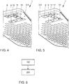
- Figure 4 shows a side view of a door handle 1 that can be used according to the invention, in the upper half of which a display device 3 is provided in a touch-sensitive surface 4.
- a loudspeaker grille 7 is arranged below the display device 3.
- buttons 8, 9, 11, 12, 13 for influencing a locking state of the means of locomotion, a target temperature, a fan strength and a position of a side window are displayed.
- the buttons 8, 9, 11, 12, 13 shown are always displayed when the door is closed.
- Figure 5 shows that in Figure 4 illustrated embodiment in its appearance with the door open. Since an adjustment of the sitting position is particularly important for the ergonomics of the operation of the means of transport before boarding the means of transport, instead of the button 12 ( Figure 4 ) a modified button 12 'is shown, by means of which stored seat settings can be called up. Instead of the button 11, a changed button 11 'is displayed in the same position. With this, an individual influence on a sitting position of the means of transport can be exerted even before boarding the means of transport, without using the operating elements (not shown) arranged less ergonomically on a border of the seat for this purpose.
- the double button 13 for controlling the window regulator is shown unchanged. Since it is not possible to lock the means of locomotion when the door is open, the buttons 8, 9 are replaced by neutral display elements 8 ', 9'.
- FIG. 6 shows a flowchart illustrating steps of an exemplary embodiment of a method according to the invention for supporting a user of a means of locomotion.
- a change in an operating state of the means of locomotion is determined. For example, a signal is generated by a microswitch in the door area, through which the opening of a driver's door is recognized.
- a position of a button for operating a seat setting is changed.
Landscapes
- Engineering & Computer Science (AREA)
- Transportation (AREA)
- Mechanical Engineering (AREA)
- Chemical & Material Sciences (AREA)
- Combustion & Propulsion (AREA)
- Automation & Control Theory (AREA)
- Human Computer Interaction (AREA)
- Steering Controls (AREA)
- User Interface Of Digital Computer (AREA)
- Instrument Panels (AREA)
- Air-Conditioning For Vehicles (AREA)
- Lock And Its Accessories (AREA)
Description
- Die vorliegende Erfindung betrifft eine Anordnung, ein Fortbewegungsmittel sowie ein Verfahren zur Unterstützung eines Anwenders eines Fortbewegungsmittels. Insbesondere betrifft die vorliegende Erfindung eine Ergonomieverbesserung bei der Bedienung von Schaltflächen und sonstigen Bedienelementen in einem Fortbewegungsmittel.
-
WO 2015/079676 A1 undWO 2012/156029 A1 offenbaren Verfahren zur geschwindigkeitsabhängigen Freigabe von Anzeigeinhalten in einem Fortbewegungsmittel. Sofern eine vorbestimmte Geschwindigkeit überschritten wird, wird die Anzeige von Informationen auf einem mobilen tragbaren Anwenderendgerät unterbunden; wird die Geschwindigkeit reduziert, wird die Anzeige wieder freigegeben. -
US 7,826,934 B1 offenbart ein Fahrzeuginterieur, bei welchem Komponenten desselben in einem verhüllten Modus dem Blick eines Betrachters entzogen werden. In einem Arbeitsmodus wird der Blick auf die Komponenten wieder freigegeben. - Das nicht vorveröffentliches Dokument
EP3484738 A wurde ebenfalls berücksichtigt. - Üblicherweise sind die Bedieneinrichtungen, mittels welcher beispielsweise die Heiz-/ Klimaanlage, Türverriegelung, etc. angesteuert werden können, in Hardware realisiert. Hierdurch ist die Position des Bedienelementes dauerhaft festgelegt. Zwar werden moderne Fortbewegungsmittel mit immer mehr Bildschirmfläche versehen, auf welcher in Software ausgestaltete Bedienelemente für Funktionsaufrufe angezeigt werden können. Jedoch bleiben die im Stand der Technik bekannten Verfahren hinter den technischen Möglichkeiten zurück. Es ist eine Aufgabe der vorliegenden Erfindung, das vorstehend identifizierte Potential zu nutzen.
- Die vorstehend identifizierte Aufgabe wird erfindungsgemäß durch ein Verfahren gemäß Anspruch 1 zur
- Unterstützung eines Anwenders eines Fortbewegungsmittels gelöst. Der Anwender kann beispielsweise der Führer, insbesondere der Fahrer/Pilot, des Fortbewegungsmittels sein. Entsprechend kann das Fortbewegungsmittel als Pkw, Transporter, LKW, Luft- und/oder Wasserfahrzeug ausgestaltet sein. Zunächst wird eine Veränderung eines Betriebszustandes des Fortbewegungsmittels ermittelt. Dies kann beispielsweise der Wechsel von einem stehenden Zustand in einen fahrenden Zustand, der Wechsel von einem manuellen Führen zu einem hoch automatisierten Fahren, das Öffnen einer Tür des Fortbewegungsmittels o. ä. sein. Da sich hierdurch ergonomische Umstände für den Anwender des Fortbewegungsmittels ändern können, wird erfindungsgemäß im Ansprechen auf die Veränderung des Betriebszustandes eine Position einer Schaltfläche zur Bedienung einer Funktion des Fortbewegungsmittels verändert. Insbesondere wird die Schaltfläche an einen solchen Ort verbracht, an welchem der Anwender sie im neuen Betriebszustand des Fortbewegungsmittels einfacher und ergonomischer erreichen kann. Im Ergebnis erhöht sich die Ergonomie des Fortbewegungsmittels, wodurch ggf. auch seine Verkehrssicherheit erhöht werden kann, da der Anwender weniger ermüdet.
- Gemäß einem zweiten Aspekt der vorliegenden Erfindung wird eine Anordnung gemäß Anspruch 2 zur Unterstützung eines Anwenders eines Fortbewegungsmittels vorgeschlagen. Die Anordnung kann als elektronisches Steuergerät ausgestaltet sein. Sie umfasst einen Signaleingang, welcher beispielsweise einen Busteilnehmer und/oder elektrische Kontakte zur Entgegennahme von Signalen repräsentierend eine Veränderung eines Betriebszustandes des Fortbewegungsmittels aufweisen kann. Eine Auswerteeinheit kann einen programmierbaren Prozessor, Mikrocontroller o. ä. umfassen und ist zur Ausführung der erfindungsgemäßen Schritte eingerichtet. Ein Signalausgang ermöglicht die Einflussnahme auf die Position der Schaltfläche. Somit ist die Anordnung eingerichtet, in Verbindung mit der Auswerteeinheit über den Signaleingang eine Veränderung eines Betriebszustandes des Fortbewegungsmittels zu ermitteln. Im Ansprechen darauf ist die Auswerteeinheit eingerichtet, über den Signalausgang eine Position einer Schaltfläche zur Bedienung einer Funktion des Fortbewegungsmittels zu verändern, um die Ergonomie des Fortbewegungsmittels zu verbessern. Hierbei wird die Position der Schaltfläche derart verändert, dass sie im neu hergestellten Betriebszustand des Fortbewegungsmittels für den Anwender besser und ergonomischer zu erreichen ist. Mit anderen Worten ist die Anordnung eingerichtet, ein erfindungsgemäßes Verfahren gemäß dem erstgenannten Erfindungsaspekt auszuführen. Der Signalausgang kann beispielsweise mit einer Grafikkarte o. ä. verbunden sein, sodass die Auswerteeinheit die Anzeige der Schaltfläche an der veränderten Position veranlassen oder selbstständig vornehmen kann.
- Unabhängig vom vorgenannten Erfindungsaspekt kann die Position der Schaltfläche von einem Lenkrad in eine Türinnenfläche/Türverkleidung wandern, um beispielsweise in einem hochautomatisierten Fahrbetrieb eine ehemals auf dem nun nicht mehr in ergonomischer Reichweite befindlichen Lenkrad angezeigtes Bedienelement über die auf der Armauflage der Türinnenverkleidung ruhende Hand bedienen zu können. In entsprechender Weise kann die Schaltfläche vom Lenkrad zur Mittelkonsole "wandern", wo der Fahrer sie mit der rechten, der Beifahrer mit der linken Hand ergonomisch einwandfrei betätigen kann. Entsprechend können die Positionen vom Armaturenbrett (z. B. Kombiinstrument und/oder zentrales Informationsdisplay) in die Türverkleidung oder in die Mittelkonsole verlagert werden. Nimmt der Anwender wieder Platz auf dem Fahrersitz, kann dies beispielsweise durch eine Sitzbelegungssensorik erkannt werden und zum Anlass für ein Absenken der Anzeigeposition der Schaltfläche genommen werden. Hierbei kann die Position der Schaltfläche beispielsweise auch innerhalb ein und derselben Anzeigeeinrichtung verändert werden.
- Die Unteransprüche zeigen bevorzugte Weiterbildungen.
- Die Gestalt der Schaltfläche kann in Abhängigkeit der jeweiligen Anzeigetechnologie, der zur Verfügung stehenden Fläche sowie in Abhängigkeit optischer und ergonomischer Gesichtspunkte modifiziert werden, wenn sie von einer ersten Position an eine zweite Position verlagert wird. Wichtig ist erfindungsgemäß lediglich, dass die Schaltfläche sowohl vor als auch nach dem Verändern ihrer Position ein und dieselbe proprietäre Funktion bedient.
- Die durch die Schaltfläche anwählbare Funktion kann beispielsweise eine Einstellung einer Sitzgelegenheit und/oder eines Lenkhandrades ermöglichen. Insbesondere solche Funktionen werden von Anwendern bevorzugt vor dem Besteigen des Fortbewegungsmittels angepasst, um bequem und ergonomisch Platz nehmen zu können. Ihre Bedienung ist jedoch mindestens ebenso wichtig, nachdem der Anwender im Fortbewegungsmittel Platz genommen hat. Für beide Anwenderpositionen sind jedoch unterschiedliche Schaltflächenpositionen ergonomisch.
- Dieser Zielkonflikt kann erfindungsgemäß aufgelöst werden. Weitere Beispiele für Funktionen, welche die erfindungsgemäß verschobene Schaltfläche auslösen kann, sind eine Türentriegelung/Türschloss und alternativ oder zusätzlich ein elektrischer Fensterheber. Die vorgenannten Beispiele können vom Fachmann beliebig ergänzt und aktualisiert werden.
- Gemäß einem dritten Aspekt der vorliegenden Erfindung wird ein Fortbewegungsmittel vorgeschlagen, welches eine Anzeigeeinrichtung (bevorzugt mit einer berührungsempfindlichen Eingabeoberfläche) und eine Anordnung gemäß dem zweitgenannten Erfindungsaspekt aufweist. Somit verwirklicht auch das Fortbewegungsmittel, welches als Pkw, Transporter, LKW, Luft- und/oder Wasserfahrzeug ausgestaltet sein kann, die Merkmale, Merkmalskombinationen und die sich aus diesen ergebenden Vorteile der erfindungsgemäßen Anordnung, sodass zur Vermeidung von Wiederholungen auf die obigen Ausführungen verwiesen wird.
- Nachfolgend werden Ausführungsbeispiele der vorliegenden Erfindung unter Bezugnahme auf die beigefügten Zeichnungen beschrieben. Es zeigen:
- Figur 1
- ein Ausführungsbeispiel eines erfindungsgemäß ausgestalteten Fortbewegungsmittels in einem ersten Betriebszustand;
- Figur 2
- ein Ausführungsbeispiel eines erfindungsgemäß ausgestalteten Fortbewegungsmittels in einem zweiten Betriebszustand;
- Figur 3
- eine schematische Darstellung eines Ausführungsbeispiels einer erfindungsgemäßen Anordnung;
- Figur 4
- eine Seitenansicht eines erfindungsgemäß verwendbaren Türgriffs in einem ersten Betriebszustand;
- Figur 5
- eine Seitenansicht eines erfindungsgemäß verwendbaren Türgriffs in einem zweiten Betriebszustand; und
- Figur 6
- ein Flussdiagramm veranschaulichend Schritte eines Ausführungsbeispiels eines erfindungsgemäßen Verfahrens.
-
Figur 1 zeigt einen Fahrerarbeitsplatz eines Pkws 10 eines Ausführungsbeispiels eines erfindungsgemäßen Fortbewegungsmittels. Ein Multifunktionslenkrad 15 weist Schaltflächen 16, 17 auf, welche der Anwender mit dem Daumen ergonomisch bedienen kann, sofern er den Fahrerarbeitsplatz für die manuelle Führung des Pkws 10 eingerichtet hat. Ein zentrales Informationsdisplay 18 als Anzeigeeinrichtung weist zwei Schaltflächen 19, 20 auf, welche zur Bedienung einer jeweiligen Funktion des Pkws 10 dienen. Wechselt der Anwender in einen hochautomatisierten Fahrbetrieb, kann er beispielweise seine Sitzposition derart modifizieren, dass er einen größeren Abstand zum Multifunktionslenkrad 15 einnimmt. Hierdurch wird im Falle eines Crashs die Verletzungsgefahr verringert. Jedoch wächst auch der Abstand des Anwenders zu den Schaltflächen 16, 17, 19, 20. Die Fahrertür 23a weist einen Türgriff 1 mit einem Griffstück 2 und einer Anzeigeeinrichtung 3 auf. Die Anzeigeeinrichtung 3 ist mit einer berührungsempfindlichen Bedienoberfläche 4 nach Art eines Touchscreens versehen. Die Anzeigeeinrichtung 3 stellt Schaltflächen 21, 22 in räumlicher Nähe zu einem unterhalb angeordneten Lautsprechergitter 7 dar. Im Vergleich hierzu weist die Beifahrertür 23b einen herkömmlichen Türgriff 28 auf. Ein in der Mittelkonsole 32 angeordneter Touchscreen 33 zeigt bei geschlossenen Türen keine Schaltflächen an. -
Figur 2 zeigt den inFigur 1 dargestellten Fahrerarbeitsplatz nach dem Öffnen der Türen 23a, 23b. Um die Bedienbarkeit der Schaltflächen 19, 20 (sieheFigur 1 ) für den Anwender (Beifahrer) aus einer neben dem Pkw 10 stehenden Position zu verbessern, sind die Schaltflächen 19', 20' nun rechts auf der Anzeigeeinrichtung 18 dargestellt. Auf diese Weise ist ihr Abstand von der Beifahrertür 23b geringer. Hierdurch sind sie ergonomischer für den Beifahrer bedienbar, solange dieser noch nicht in den Pkw 10 eingestiegen ist. Die inFigur 1 dargestellten Schaltflächen 21, 22 sind innerhalb der Anzeigeeinrichtung 3 als ortsveränderte Schaltflächen 21', 22' an den oberen Rand der Anzeigeeinrichtung 3 gewandert, sodass sie für den an der Fahrertür 23a stehenden Fahrer ergonomischer erreichbar sind. Zusätzliche Schaltflächen 16', 17' auf dem Touchscreen 33 in der Mittelkonsole 32 veranschaulichen die Erscheinung des Touchscreens 33 während eines hochautomatisierten Fahrbetriebes, in welchem die Schaltflächen 16, 17 im Multifunktionslenkrad 15 vom Anwender nicht besonders ergonomisch bedient werden können. -
Figur 3 zeigt eine schematische Darstellung eines elektronischen Steuergerätes 24 als Ausführungsbeispiel einer erfindungsgemäßen Anordnung. Das elektronische Steuergerät 24 weist einen Busteilnehmer als Signaleingang 25 zur Entgegennahme von Signalen repräsentierend eine Veränderung eines Betriebszustandes eines Fortbewegungsmittels auf. Der Signaleingang 25 ist informationstechnisch mit einem programmierbaren Prozessor 26 als Auswerteeinrichtung verbunden. Sofern der programmierbare Prozessor 26 aus den erhaltenen Signalen ermittelt, dass sich ein vordefinierter Betriebszustand eingestellt hat, veranlasst er über den informationstechnisch angebundenen Signalausgang 27 (optional ebenfalls mit einem Busteilnehmer ausgestattet) eine Veränderung einer auf einer Anzeigeeinheit des Fortbewegungsmittels dargestellten Schaltfläche. Hierbei wird die Schaltfläche von einer ersten Position zu einer zweiten Position innerhalb des Fortbewegungsmittels verbracht, um die fortwährende Ergonomie in erfindungsgemäßer Weise zu gewährleisten. -
Figur 4 zeigt eine Seitenansicht eines erfindungsgemäß verwendbaren Türgriffs 1, in dessen oberer Hälfte eine Anzeigeeinrichtung 3 in einer berührungsempfindlichen Oberfläche 4 versehen ist. Unterhalb der Anzeigeeinrichtung 3 ist ein Lautsprechergitter 7 angeordnet. Auf der Anzeigeeinrichtung 3 werden Schaltflächen 8, 9, 11, 12, 13 zur Einflussnahme auf einen Verriegelungszustand des Fortbewegungsmittels, eine Solltemperatur, eine Lüfterstärke sowie eine Position einer Seitenscheibe angezeigt. Die dargestellten Schaltflächen 8, 9, 11, 12, 13 werden stets bei geschlossener Tür angezeigt. -
Figur 5 zeigt das inFigur 4 dargestellte Ausführungsbeispiel in seiner Erscheinungsform bei geöffneter Tür. Da bereits vor dem Besteigen des Fortbewegungsmittels eine Anpassung der Sitzposition besonders wichtig für die Ergonomie der Bedienung des Fortbewegungsmittels ist, wird anstatt der Schaltfläche 12 (Figur 4 ) eine modifizierte Schaltfläche 12' dargestellt, mittels welcher gespeicherte Sitzeinstellungen abgerufen werden können. Anstatt der Schaltfläche 11 wird an derselben Position eine geänderte Schaltfläche 11' angezeigt. Mit dieser kann bereits vor dem Besteigen des Fortbewegungsmittels individueller Einfluss auf eine Sitzposition des Fortbewegungsmittels genommen werden, ohne hierzu die weniger ergonomisch an einer Einfassung der Sitzfläche angeordneten (nicht dargestellten) Bedienelemente zu verwenden. Die doppelte Schaltfläche 13 zur Ansteuerung des Fensterhebers wird unverändert dargestellt. Da die Verriegelung des Fortbewegungsmittels bei geöffneter Tür nicht möglich ist, werden die Schaltflächen 8, 9 durch neutrale Anzeigeelemente 8', 9' ersetzt. -
Figur 6 zeigt ein Flussdiagramm veranschaulichend Schritte eines Ausführungsbeispiels eines erfindungsgemäßen Verfahrens zur Unterstützung eines Anwenders eines Fortbewegungsmittels. In Schritt 100 wird eine Veränderung eines Betriebszustandes des Fortbewegungsmittels ermittelt. Beispielsweise wird ein Signal durch einen Mikroschalter im Türbereich erzeugt, durch welches das Öffnen einer Fahrertür erkannt wird. Im Ansprechen darauf wird in Schritt 200 eine Position einer Schaltfläche zur Bedienung einer Sitzeinstellung verändert. -
- 1
- Türgriff
- 2
- Griffstück
- 3
- Anzeigeeinrichtung
- 4
- Berührungsempfindliche Oberfläche
- 7
- Lautsprechergitter
- 8, 8', 9, 9'
- Schaltflächen
- 10
- Pkw
- 11, 11', 12, 12', 13
- Schaltflächen
- 15
- Multifunktionslenkrad
- 16, 16', 17, 17'
- Schaltflächen
- 18
- Anzeigeeinrichtung
- 19, 19', 20, 20', 21, 21', 22, 22'
- Schaltflächen
- 23a
- Fahrertür
- 23b
- Beifahrertür
- 24
- Elektronisches Steuergerät
- 25
- Signaleingang
- 26
- Programmierbarer Prozessor
- 27
- Signalausgang
- 100,200
- Verfahrensschritte
Claims (6)
- Verfahren zur Unterstützung eines Anwenders eines Fortbewegungsmittels (10) umfassend die Schritte:- Ermitteln (100) einer Veränderung eines Betriebszustandes des Fortbewegungsmittels (10) und im Ansprechen darauf,- Anzeigen (200) einer Schaltfläche (8, 9, 11, 12, 13, 16, 17, 19, 20, 21, 22) zur Bedienung einer Funktion des Fortbewegungsmittels (10) an einer neuen Position, dadurch gekennzeichnet, dass sich die Position der Schaltfläche (8, 9, 11, 12, 13, 16, 17, 19, 20, 21, 22)- von einem Lenkrad (15) zu einer Türinnenfläche und/oder zu einer Mittelkonsole, und/oder- von einem Kombiinstrument und/oder einem zentralen Informationsdisplay (18) zu der Türinnenfläche und/oder zu der Mittelkonsole (32) verändert.
- Anordnung zur Unterstützung eines Anwenders eines Fortbewegungsmittels (10) umfassend:- einen Signaleingang (25),- eine Auswerteeinheit (26), und- einen Signalausgang (27),
wobei die Auswerteeinheit (26) eingerichtet ist,- über den Signaleingang (25) eine Veränderung eines Betriebszustandes des Fortbewegungsmittels (10) zu ermitteln und im Ansprechen darauf,- über den Signalausgang eine Schaltfläche (8, 9, 11, 12, 13, 16, 17, 19, 20, 21, 22) zur Bedienung einer Funktion des Fortbewegungsmittels (10) an einer neuen Position anzuzeigen, dadurch gekennzeichnet, dass sich die Position der Schaltfläche (8, 9, 11, 12, 13, 16, 17, 19, 20, 21, 22)- von einem Lenkrad (15) zu einer Türinnenfläche und/oder zu einer Mittelkonsole, und/oder- von einem Kombiinstrument und/oder einem zentralen Informationsdisplay (18) zu der Türinnenfläche und/oder zu der Mittelkonsole (32) verändert. - Verfahren nach Anspruch 1 oder Anordnung nach Anspruch 2, wobei die Veränderung des Betriebszustandes durch einen Wechsel- eines Türöffnungszustandes und/oder- einer Sitzbelegung und/oder- von Fahrt zu Stillstand des Fortbewegungsmittels (10) oder andersherum und/oder- von automatischer Führung zu manueller Führung des Fortbewegungsmittels (10) oder andersherum
gekennzeichnet ist. - Verfahren nach einem der Ansprüche 1 oder 3 oder Anordnung nach einem der Ansprüche 2 oder 3, wobei die Position der Schaltfläche (8, 9, 11, 12, 13, 16, 17, 19, 20, 21, 22) im Ansprechen auf das Öffnen einer Tür (23a, 23b) des Fortbewegungsmittels (10) erhöht wird.
- Verfahren nach einem der Ansprüche 1, 3 oder 4 oder Anordnung nach einem der Ansprüche 2 bis 4, wobei die Funktion- eine Einstellung einer Sitzgelegenheit und/oder eines Lenkhandrades (15) und/oder- eine Türentriegelung und/oder- einen Fensterhebemotor
betrifft. - Fortbewegungsmittel umfassend- eine Anzeigeeinrichtung (3, 18) und- eine Anordnung nach einem der vorstehenden Ansprüche 2 bis 5.
Applications Claiming Priority (2)
| Application Number | Priority Date | Filing Date | Title |
|---|---|---|---|
| DE102016218694.9A DE102016218694A1 (de) | 2016-09-28 | 2016-09-28 | Anordnung, Fortbewegungsmittel und Verfahren zur Unterstützung eines Anwenders eines Fortbewegungsmittels |
| PCT/EP2017/073618 WO2018060007A1 (de) | 2016-09-28 | 2017-09-19 | Anordnung, fortbewegungsmittel und verfahren zur unterstützung eines anwenders eines fortbewegungsmittels |
Publications (2)
| Publication Number | Publication Date |
|---|---|
| EP3519236A1 EP3519236A1 (de) | 2019-08-07 |
| EP3519236B1 true EP3519236B1 (de) | 2021-12-01 |
Family
ID=59966728
Family Applications (1)
| Application Number | Title | Priority Date | Filing Date |
|---|---|---|---|
| EP17772363.2A Active EP3519236B1 (de) | 2016-09-28 | 2017-09-19 | Anordnung, fortbewegungsmittel und verfahren zur unterstützung eines anwenders eines fortbewegungsmittels |
Country Status (5)
| Country | Link |
|---|---|
| US (1) | US11001145B2 (de) |
| EP (1) | EP3519236B1 (de) |
| CN (1) | CN109661320B (de) |
| DE (1) | DE102016218694A1 (de) |
| WO (1) | WO2018060007A1 (de) |
Families Citing this family (8)
| Publication number | Priority date | Publication date | Assignee | Title |
|---|---|---|---|---|
| DE102016218693A1 (de) * | 2016-09-28 | 2018-03-29 | Volkswagen Aktiengesellschaft | Türgriff, Türinnenverkleidung und Fortbewegungsmittel |
| DE102018207932B4 (de) * | 2018-05-18 | 2021-06-02 | Audi Ag | Kraftfahrzeug mit einer Anzeigevorrichtung mit zwei einteilig miteinander ausgebildeten und gewinkelt zueinander angeordneten Teilbereichen |
| DE102018116991A1 (de) * | 2018-07-13 | 2020-01-16 | Grammer Ag | Fahrzeugsitz mit Bedieneinrichtung |
| DE102018117000B4 (de) * | 2018-07-13 | 2020-04-02 | Grammer Ag | Fahrzeugsitz mit Bedieneinrichtung |
| FR3086080A1 (fr) * | 2018-09-17 | 2020-03-20 | Psa Automobiles Sa | Dispositif d’affichage a ecran tactile affichant des imagettes de commande d’equipements en fonction du contexte, pour une porte d’un vehicule |
| CN111497611A (zh) * | 2020-04-03 | 2020-08-07 | 广州小鹏汽车科技有限公司 | 一种车辆交互方法和装置 |
| US12371185B2 (en) | 2021-06-04 | 2025-07-29 | Rockwell Collins, Inc. | Vehicle operator monitoring system with smart active engagement and disengagement |
| DE102021122345A1 (de) | 2021-08-30 | 2023-03-02 | Bayerische Motoren Werke Aktiengesellschaft | Fortbewegungsmittel und Anwenderschnittstelle für ein Fortbewegungsmittel zur Ausgabe thermischer Rückmeldungen an einen Anwender |
Citations (1)
| Publication number | Priority date | Publication date | Assignee | Title |
|---|---|---|---|---|
| EP3484738A1 (de) * | 2016-07-13 | 2019-05-22 | Audi AG | Fahrzeug mit einer bedien- und anzeigevorrichtung und verfahren zum betreiben eines solchen fahrzeugs |
Family Cites Families (39)
| Publication number | Priority date | Publication date | Assignee | Title |
|---|---|---|---|---|
| US7650212B2 (en) * | 1995-06-07 | 2010-01-19 | Automotive Technologies International, Inc. | Pedal adjustment system and method |
| DE19941973C5 (de) * | 1999-09-03 | 2012-05-16 | Volkswagen Ag | Verfahren und Vorrichtung zur aktiven Hilfestellung eines Kraftfahrzeugführers in einem Kraftfahrzeug |
| US20150149079A1 (en) * | 1999-12-15 | 2015-05-28 | American Vehicular Sciences Llc | Vehicle heads-up display navigation system |
| US8768286B2 (en) * | 2001-10-24 | 2014-07-01 | Mouhamad Ahmad Naboulsi | Hands on steering wheel vehicle safety control system |
| DE10339050A1 (de) | 2003-08-25 | 2005-03-31 | Siemens Ag | Steuerung der Darstellung einer Anzeige |
| EP1689608B1 (de) * | 2003-11-18 | 2008-04-16 | Matsushita Electric Corporation Of America | Multimoden-mehrzonen-schnittstelle |
| DE102005060605A1 (de) | 2005-12-17 | 2007-06-21 | Bayerische Motoren Werke Ag | Bedieneinrichtung für ein Fahrzeug und Set von Bedieneinrichtungen |
| JP4572889B2 (ja) * | 2006-11-20 | 2010-11-04 | 株式会社デンソー | 自動車用ユーザーもてなしシステム |
| US7826934B1 (en) | 2006-11-27 | 2010-11-02 | Honda Motor Co, Ltd. | Theft and tamper resistant vehicle interior |
| US11203355B2 (en) * | 2011-04-22 | 2021-12-21 | Emerging Automotive, Llc | Vehicle mode for restricted operation and cloud data monitoring |
| DE102011101808A1 (de) * | 2011-05-17 | 2012-11-22 | Volkswagen Ag | Verfahren und System zum Bereitstellen einer Nutzerschnittstelle in einem Fahrzeug |
| DE102011111578A1 (de) | 2011-08-20 | 2013-02-21 | Volkswagen Aktiengesellschaft | Anzeigevorrichtung für ein Fahrzeug |
| US10862764B2 (en) * | 2011-11-16 | 2020-12-08 | AutoConnect Holdings, LLC | Universal console chassis for the car |
| US20140309871A1 (en) * | 2013-04-15 | 2014-10-16 | Flextronics Ap, Llc | User gesture control of vehicle features |
| DE102012014655A1 (de) | 2012-07-24 | 2014-03-06 | Bomag Gmbh | Bedieneinheit für eine Baumaschine und Verfahren zum Betreiben der Bedieneinheit |
| WO2014030190A1 (ja) * | 2012-08-24 | 2014-02-27 | ルネサスエレクトロニクス株式会社 | 制御ユニット、半導体装置及び制御ユニットの制御方法 |
| WO2014143563A1 (en) * | 2013-03-14 | 2014-09-18 | Flextronics Ap, Llc | Occupant sharing of displayed content in vehicles |
| CN104379414B (zh) * | 2013-04-15 | 2018-05-29 | 自动连接控股有限责任公司 | 用户接口和基于用户简档的虚拟个性呈现 |
| EP2857276B1 (de) * | 2013-08-20 | 2018-12-12 | Harman International Industries, Incorporated | Fahrerassistenzsystem |
| JP5871866B2 (ja) * | 2013-08-26 | 2016-03-01 | 本田技研工業株式会社 | スマートエントリシステム |
| GB2521124B (en) | 2013-11-29 | 2020-12-23 | Denso Corp | Method for an in-vehicle apparatus, an in-vehicle apparatus and a vehicle |
| US20150294169A1 (en) * | 2014-04-10 | 2015-10-15 | Magna Electronics Inc. | Vehicle vision system with driver monitoring |
| US20190279440A1 (en) * | 2014-09-23 | 2019-09-12 | Autoconnect Holdings Llc | Fleetwide vehicle telematics systems and methods |
| US9937839B2 (en) * | 2014-12-31 | 2018-04-10 | Harman International Industries, Incorporated | Feedback by modifying stiffness |
| EP3085868B1 (de) * | 2015-04-20 | 2020-11-25 | Volvo Car Corporation | Anordnung und verfahren zum betrieb von fahrzeugfenstern |
| DE102015006655A1 (de) | 2015-05-22 | 2016-02-18 | Daimler Ag | Kraftfahrzeug mit mindestens einer Projektionseinrichtung |
| US10384519B1 (en) * | 2016-01-12 | 2019-08-20 | Apple Inc. | Doors with adaptive positioning |
| KR101976419B1 (ko) * | 2016-03-18 | 2019-05-09 | 엘지전자 주식회사 | 차량용 도어 제어 장치 및 차량 |
| KR101763586B1 (ko) * | 2016-03-22 | 2017-08-07 | 현대자동차주식회사 | 도어 개폐 장치, 그를 가지는 차량 및 그 제어 방법 |
| JP6365600B2 (ja) * | 2016-06-30 | 2018-08-01 | マツダ株式会社 | 車両用表示装置 |
| US11104229B2 (en) * | 2016-07-11 | 2021-08-31 | Shanghai Yanfeng Jinqiao Automotive Trim Systems Co. Ltd. | Vehicle interior component |
| CN108146345B (zh) * | 2016-12-06 | 2021-03-30 | Lg电子株式会社 | 车辆控制装置及包括该车辆控制装置的车辆 |
| KR102384642B1 (ko) * | 2017-04-24 | 2022-04-08 | 엘지전자 주식회사 | 차량에 구비된 차량 제어 장치 및 차량의 제어방법 |
| WO2018236012A1 (ko) * | 2017-06-22 | 2018-12-27 | 엘지전자 주식회사 | 입출력 장치 |
| KR102387613B1 (ko) * | 2017-06-26 | 2022-04-15 | 엘지전자 주식회사 | 차량용 인터페이스 시스템 |
| KR101934294B1 (ko) * | 2017-09-05 | 2019-01-02 | 엘지전자 주식회사 | 디스플레이 장치 및 그것을 포함하는 차량 |
| KR102041965B1 (ko) * | 2017-12-26 | 2019-11-27 | 엘지전자 주식회사 | 차량에 구비된 디스플레이 장치 |
| KR102676239B1 (ko) * | 2018-12-13 | 2024-06-20 | 현대자동차주식회사 | 디스플레이를 구비한 스마트키를 이용한 차량용 제어 장치 및 그 제어 방법 |
| US20200290513A1 (en) * | 2019-03-13 | 2020-09-17 | Light Field Lab, Inc. | Light field display system for vehicle augmentation |
-
2016
- 2016-09-28 DE DE102016218694.9A patent/DE102016218694A1/de not_active Withdrawn
-
2017
- 2017-09-19 CN CN201780054319.4A patent/CN109661320B/zh active Active
- 2017-09-19 US US16/337,427 patent/US11001145B2/en active Active
- 2017-09-19 EP EP17772363.2A patent/EP3519236B1/de active Active
- 2017-09-19 WO PCT/EP2017/073618 patent/WO2018060007A1/de not_active Ceased
Patent Citations (1)
| Publication number | Priority date | Publication date | Assignee | Title |
|---|---|---|---|---|
| EP3484738A1 (de) * | 2016-07-13 | 2019-05-22 | Audi AG | Fahrzeug mit einer bedien- und anzeigevorrichtung und verfahren zum betreiben eines solchen fahrzeugs |
Also Published As
| Publication number | Publication date |
|---|---|
| EP3519236A1 (de) | 2019-08-07 |
| US11001145B2 (en) | 2021-05-11 |
| CN109661320A (zh) | 2019-04-19 |
| US20190241071A1 (en) | 2019-08-08 |
| CN109661320B (zh) | 2022-08-19 |
| DE102016218694A1 (de) | 2018-03-29 |
| WO2018060007A1 (de) | 2018-04-05 |
Similar Documents
| Publication | Publication Date | Title |
|---|---|---|
| EP3519236A1 (de) | Anordnung, fortbewegungsmittel und verfahren zur unterstützung eines anwenders eines fortbewegungsmittels | |
| EP3212453B1 (de) | Verfahren und system zum betreiben einer berührungssensitiven anzeigeeinrichtung eines kraftwagens | |
| EP3067244B1 (de) | Kraftfahrzeug mit situationsadaptivem automatischem fahrmodus | |
| EP3393856A1 (de) | Kraftfahrzeug mit schalttafelmodul | |
| DE102012214017A1 (de) | System zum verhindern des lösens eines blickes zur verwendungwährend des fahrens eines fahrzeugs | |
| EP2960099B1 (de) | Anwenderschnittstelle und verfahren zum anpassen einer einstellung eines fortbewegungsmittels mittels einer anzeigeeinheit einer anwenderschnittstelle | |
| DE102014202528A1 (de) | Verfahren und Vorrichtung zum Verändern einer Position zumindest einer Komponente eines Infotainmentsystems im Innenraum eines Fahrzeugs | |
| DE102011006212A1 (de) | Verfahren zum Differenzieren haptischer Empfindungen durch ein Auswahlmenü eines Drehschalters | |
| WO2011110294A1 (de) | Verfahren und vorrichtung zum betreiben einer benutzerschnittstelle | |
| EP3519250B1 (de) | Türgriff, türinnenverkleidung und fortbewegungsmittel | |
| DE102011010229A1 (de) | Vorrichtung zur Bedienung mehrerer unterschiedlicher Funktionen eines Kraftfahrzeugs | |
| DE102014012550A1 (de) | Kraftfahrzeug-Bedienungsvorrichtung | |
| DE102016007024A1 (de) | Lenkrad mit Bedienelementen und Verfahren zur Einstellung einer Funktion für ein Fahrzeug | |
| EP3508967A1 (de) | Verfahren zum betreiben einer mensch-maschinen-schnittstelle sowie mensch-maschinen-schnittstelle | |
| EP1119463B1 (de) | Bedieneinheit für ein fahrzeug | |
| DE102014003947B4 (de) | Bedienvorrichtung für eine Klimaanlage eines Kraftfahrzeugs sowie Verfahren zum Steuern einer Klimaanlage eines Kraftfahrzeugs | |
| DE102020131931A1 (de) | Steuersystem und Verfahren zum Steuern von Interieurfunktionen eines Kraftfahrzeugs | |
| EP2695792B1 (de) | Vorrichtung mit einer Lenkhandhabe und einem Bedienfeld und Kraftfahrzeug | |
| EP3188922B1 (de) | Bedienvorrichtung und verfahren zum bedienen von funktionen eines fahrzeugs, insbesondere eines kraftwagens | |
| DE102019132491A1 (de) | Verstellen eines Rückspiegels an einem Fahrzeug | |
| DE102017217639B4 (de) | Vorrichtung und Verfahren zum Anzeigen einer einem Lenkwinkel eines Fahrzeugs entsprechenden Stellung eines Lenksensors | |
| DE102022110485B4 (de) | Verfahren und Steuersystem zum Aufrufen von Funktionen und zur Betätigung von Einstellungen eines Fahrzeugs | |
| DE102020204948B4 (de) | Szenarioabhängiges Anzeigen virtueller Bedienelemente in einem Fahrzeug | |
| EP3418101B1 (de) | Kombinationsinstrument zur hierarchiefreien funktionsauswahl | |
| EP3067227A1 (de) | Fortbewegungsmittel, anwenderschnittstelle und verfahren zur bedienung einer heizklimaanlage eines fortbewegungsmittels |
Legal Events
| Date | Code | Title | Description |
|---|---|---|---|
| STAA | Information on the status of an ep patent application or granted ep patent |
Free format text: STATUS: UNKNOWN |
|
| STAA | Information on the status of an ep patent application or granted ep patent |
Free format text: STATUS: THE INTERNATIONAL PUBLICATION HAS BEEN MADE |
|
| PUAI | Public reference made under article 153(3) epc to a published international application that has entered the european phase |
Free format text: ORIGINAL CODE: 0009012 |
|
| STAA | Information on the status of an ep patent application or granted ep patent |
Free format text: STATUS: REQUEST FOR EXAMINATION WAS MADE |
|
| 17P | Request for examination filed |
Effective date: 20190429 |
|
| AK | Designated contracting states |
Kind code of ref document: A1 Designated state(s): AL AT BE BG CH CY CZ DE DK EE ES FI FR GB GR HR HU IE IS IT LI LT LU LV MC MK MT NL NO PL PT RO RS SE SI SK SM TR |
|
| AX | Request for extension of the european patent |
Extension state: BA ME |
|
| RIN1 | Information on inventor provided before grant (corrected) |
Inventor name: TRABUCCO, LUIGI |
|
| DAV | Request for validation of the european patent (deleted) | ||
| DAX | Request for extension of the european patent (deleted) | ||
| GRAP | Despatch of communication of intention to grant a patent |
Free format text: ORIGINAL CODE: EPIDOSNIGR1 |
|
| STAA | Information on the status of an ep patent application or granted ep patent |
Free format text: STATUS: GRANT OF PATENT IS INTENDED |
|
| INTG | Intention to grant announced |
Effective date: 20210916 |
|
| GRAS | Grant fee paid |
Free format text: ORIGINAL CODE: EPIDOSNIGR3 |
|
| GRAA | (expected) grant |
Free format text: ORIGINAL CODE: 0009210 |
|
| STAA | Information on the status of an ep patent application or granted ep patent |
Free format text: STATUS: THE PATENT HAS BEEN GRANTED |
|
| AK | Designated contracting states |
Kind code of ref document: B1 Designated state(s): AL AT BE BG CH CY CZ DE DK EE ES FI FR GB GR HR HU IE IS IT LI LT LU LV MC MK MT NL NO PL PT RO RS SE SI SK SM TR |
|
| REG | Reference to a national code |
Ref country code: GB Ref legal event code: FG4D Free format text: NOT ENGLISH |
|
| REG | Reference to a national code |
Ref country code: AT Ref legal event code: REF Ref document number: 1451443 Country of ref document: AT Kind code of ref document: T Effective date: 20211215 Ref country code: CH Ref legal event code: EP |
|
| REG | Reference to a national code |
Ref country code: IE Ref legal event code: FG4D Free format text: LANGUAGE OF EP DOCUMENT: GERMAN |
|
| REG | Reference to a national code |
Ref country code: DE Ref legal event code: R096 Ref document number: 502017012153 Country of ref document: DE |
|
| REG | Reference to a national code |
Ref country code: LT Ref legal event code: MG9D |
|
| REG | Reference to a national code |
Ref country code: NL Ref legal event code: MP Effective date: 20211201 |
|
| PG25 | Lapsed in a contracting state [announced via postgrant information from national office to epo] |
Ref country code: RS Free format text: LAPSE BECAUSE OF FAILURE TO SUBMIT A TRANSLATION OF THE DESCRIPTION OR TO PAY THE FEE WITHIN THE PRESCRIBED TIME-LIMIT Effective date: 20211201 Ref country code: LT Free format text: LAPSE BECAUSE OF FAILURE TO SUBMIT A TRANSLATION OF THE DESCRIPTION OR TO PAY THE FEE WITHIN THE PRESCRIBED TIME-LIMIT Effective date: 20211201 Ref country code: FI Free format text: LAPSE BECAUSE OF FAILURE TO SUBMIT A TRANSLATION OF THE DESCRIPTION OR TO PAY THE FEE WITHIN THE PRESCRIBED TIME-LIMIT Effective date: 20211201 Ref country code: BG Free format text: LAPSE BECAUSE OF FAILURE TO SUBMIT A TRANSLATION OF THE DESCRIPTION OR TO PAY THE FEE WITHIN THE PRESCRIBED TIME-LIMIT Effective date: 20220301 |
|
| PG25 | Lapsed in a contracting state [announced via postgrant information from national office to epo] |
Ref country code: SE Free format text: LAPSE BECAUSE OF FAILURE TO SUBMIT A TRANSLATION OF THE DESCRIPTION OR TO PAY THE FEE WITHIN THE PRESCRIBED TIME-LIMIT Effective date: 20211201 Ref country code: PL Free format text: LAPSE BECAUSE OF FAILURE TO SUBMIT A TRANSLATION OF THE DESCRIPTION OR TO PAY THE FEE WITHIN THE PRESCRIBED TIME-LIMIT Effective date: 20211201 Ref country code: NO Free format text: LAPSE BECAUSE OF FAILURE TO SUBMIT A TRANSLATION OF THE DESCRIPTION OR TO PAY THE FEE WITHIN THE PRESCRIBED TIME-LIMIT Effective date: 20220301 Ref country code: LV Free format text: LAPSE BECAUSE OF FAILURE TO SUBMIT A TRANSLATION OF THE DESCRIPTION OR TO PAY THE FEE WITHIN THE PRESCRIBED TIME-LIMIT Effective date: 20211201 Ref country code: HR Free format text: LAPSE BECAUSE OF FAILURE TO SUBMIT A TRANSLATION OF THE DESCRIPTION OR TO PAY THE FEE WITHIN THE PRESCRIBED TIME-LIMIT Effective date: 20211201 Ref country code: GR Free format text: LAPSE BECAUSE OF FAILURE TO SUBMIT A TRANSLATION OF THE DESCRIPTION OR TO PAY THE FEE WITHIN THE PRESCRIBED TIME-LIMIT Effective date: 20220302 Ref country code: ES Free format text: LAPSE BECAUSE OF FAILURE TO SUBMIT A TRANSLATION OF THE DESCRIPTION OR TO PAY THE FEE WITHIN THE PRESCRIBED TIME-LIMIT Effective date: 20211201 |
|
| PG25 | Lapsed in a contracting state [announced via postgrant information from national office to epo] |
Ref country code: NL Free format text: LAPSE BECAUSE OF FAILURE TO SUBMIT A TRANSLATION OF THE DESCRIPTION OR TO PAY THE FEE WITHIN THE PRESCRIBED TIME-LIMIT Effective date: 20211201 |
|
| PG25 | Lapsed in a contracting state [announced via postgrant information from national office to epo] |
Ref country code: SM Free format text: LAPSE BECAUSE OF FAILURE TO SUBMIT A TRANSLATION OF THE DESCRIPTION OR TO PAY THE FEE WITHIN THE PRESCRIBED TIME-LIMIT Effective date: 20211201 Ref country code: SK Free format text: LAPSE BECAUSE OF FAILURE TO SUBMIT A TRANSLATION OF THE DESCRIPTION OR TO PAY THE FEE WITHIN THE PRESCRIBED TIME-LIMIT Effective date: 20211201 Ref country code: RO Free format text: LAPSE BECAUSE OF FAILURE TO SUBMIT A TRANSLATION OF THE DESCRIPTION OR TO PAY THE FEE WITHIN THE PRESCRIBED TIME-LIMIT Effective date: 20211201 Ref country code: PT Free format text: LAPSE BECAUSE OF FAILURE TO SUBMIT A TRANSLATION OF THE DESCRIPTION OR TO PAY THE FEE WITHIN THE PRESCRIBED TIME-LIMIT Effective date: 20220401 Ref country code: EE Free format text: LAPSE BECAUSE OF FAILURE TO SUBMIT A TRANSLATION OF THE DESCRIPTION OR TO PAY THE FEE WITHIN THE PRESCRIBED TIME-LIMIT Effective date: 20211201 Ref country code: CZ Free format text: LAPSE BECAUSE OF FAILURE TO SUBMIT A TRANSLATION OF THE DESCRIPTION OR TO PAY THE FEE WITHIN THE PRESCRIBED TIME-LIMIT Effective date: 20211201 |
|
| REG | Reference to a national code |
Ref country code: DE Ref legal event code: R097 Ref document number: 502017012153 Country of ref document: DE |
|
| PG25 | Lapsed in a contracting state [announced via postgrant information from national office to epo] |
Ref country code: IS Free format text: LAPSE BECAUSE OF FAILURE TO SUBMIT A TRANSLATION OF THE DESCRIPTION OR TO PAY THE FEE WITHIN THE PRESCRIBED TIME-LIMIT Effective date: 20220401 |
|
| PLBE | No opposition filed within time limit |
Free format text: ORIGINAL CODE: 0009261 |
|
| STAA | Information on the status of an ep patent application or granted ep patent |
Free format text: STATUS: NO OPPOSITION FILED WITHIN TIME LIMIT |
|
| PG25 | Lapsed in a contracting state [announced via postgrant information from national office to epo] |
Ref country code: DK Free format text: LAPSE BECAUSE OF FAILURE TO SUBMIT A TRANSLATION OF THE DESCRIPTION OR TO PAY THE FEE WITHIN THE PRESCRIBED TIME-LIMIT Effective date: 20211201 Ref country code: AL Free format text: LAPSE BECAUSE OF FAILURE TO SUBMIT A TRANSLATION OF THE DESCRIPTION OR TO PAY THE FEE WITHIN THE PRESCRIBED TIME-LIMIT Effective date: 20211201 |
|
| 26N | No opposition filed |
Effective date: 20220902 |
|
| PG25 | Lapsed in a contracting state [announced via postgrant information from national office to epo] |
Ref country code: SI Free format text: LAPSE BECAUSE OF FAILURE TO SUBMIT A TRANSLATION OF THE DESCRIPTION OR TO PAY THE FEE WITHIN THE PRESCRIBED TIME-LIMIT Effective date: 20211201 |
|
| PG25 | Lapsed in a contracting state [announced via postgrant information from national office to epo] |
Ref country code: MC Free format text: LAPSE BECAUSE OF FAILURE TO SUBMIT A TRANSLATION OF THE DESCRIPTION OR TO PAY THE FEE WITHIN THE PRESCRIBED TIME-LIMIT Effective date: 20211201 |
|
| REG | Reference to a national code |
Ref country code: CH Ref legal event code: PL |
|
| REG | Reference to a national code |
Ref country code: BE Ref legal event code: MM Effective date: 20220930 |
|
| PG25 | Lapsed in a contracting state [announced via postgrant information from national office to epo] |
Ref country code: IT Free format text: LAPSE BECAUSE OF FAILURE TO SUBMIT A TRANSLATION OF THE DESCRIPTION OR TO PAY THE FEE WITHIN THE PRESCRIBED TIME-LIMIT Effective date: 20211201 |
|
| P01 | Opt-out of the competence of the unified patent court (upc) registered |
Effective date: 20230523 |
|
| PG25 | Lapsed in a contracting state [announced via postgrant information from national office to epo] |
Ref country code: LU Free format text: LAPSE BECAUSE OF NON-PAYMENT OF DUE FEES Effective date: 20220919 |
|
| PG25 | Lapsed in a contracting state [announced via postgrant information from national office to epo] |
Ref country code: LI Free format text: LAPSE BECAUSE OF NON-PAYMENT OF DUE FEES Effective date: 20220930 Ref country code: IE Free format text: LAPSE BECAUSE OF NON-PAYMENT OF DUE FEES Effective date: 20220919 Ref country code: CH Free format text: LAPSE BECAUSE OF NON-PAYMENT OF DUE FEES Effective date: 20220930 |
|
| PG25 | Lapsed in a contracting state [announced via postgrant information from national office to epo] |
Ref country code: BE Free format text: LAPSE BECAUSE OF NON-PAYMENT OF DUE FEES Effective date: 20220930 |
|
| REG | Reference to a national code |
Ref country code: AT Ref legal event code: MM01 Ref document number: 1451443 Country of ref document: AT Kind code of ref document: T Effective date: 20220919 |
|
| REG | Reference to a national code |
Ref country code: DE Ref legal event code: R079 Ref document number: 502017012153 Country of ref document: DE Free format text: PREVIOUS MAIN CLASS: B60K0037060000 Ipc: B60K0035100000 |
|
| PG25 | Lapsed in a contracting state [announced via postgrant information from national office to epo] |
Ref country code: AT Free format text: LAPSE BECAUSE OF NON-PAYMENT OF DUE FEES Effective date: 20220919 |
|
| PG25 | Lapsed in a contracting state [announced via postgrant information from national office to epo] |
Ref country code: HU Free format text: LAPSE BECAUSE OF FAILURE TO SUBMIT A TRANSLATION OF THE DESCRIPTION OR TO PAY THE FEE WITHIN THE PRESCRIBED TIME-LIMIT; INVALID AB INITIO Effective date: 20170919 |
|
| PG25 | Lapsed in a contracting state [announced via postgrant information from national office to epo] |
Ref country code: CY Free format text: LAPSE BECAUSE OF FAILURE TO SUBMIT A TRANSLATION OF THE DESCRIPTION OR TO PAY THE FEE WITHIN THE PRESCRIBED TIME-LIMIT Effective date: 20211201 |
|
| PG25 | Lapsed in a contracting state [announced via postgrant information from national office to epo] |
Ref country code: MK Free format text: LAPSE BECAUSE OF FAILURE TO SUBMIT A TRANSLATION OF THE DESCRIPTION OR TO PAY THE FEE WITHIN THE PRESCRIBED TIME-LIMIT Effective date: 20211201 |
|
| PG25 | Lapsed in a contracting state [announced via postgrant information from national office to epo] |
Ref country code: MT Free format text: LAPSE BECAUSE OF FAILURE TO SUBMIT A TRANSLATION OF THE DESCRIPTION OR TO PAY THE FEE WITHIN THE PRESCRIBED TIME-LIMIT Effective date: 20211201 |
|
| PGFP | Annual fee paid to national office [announced via postgrant information from national office to epo] |
Ref country code: DE Payment date: 20250930 Year of fee payment: 9 |
|
| PGFP | Annual fee paid to national office [announced via postgrant information from national office to epo] |
Ref country code: GB Payment date: 20250923 Year of fee payment: 9 |
|
| PGFP | Annual fee paid to national office [announced via postgrant information from national office to epo] |
Ref country code: FR Payment date: 20250925 Year of fee payment: 9 |
|
| PG25 | Lapsed in a contracting state [announced via postgrant information from national office to epo] |
Ref country code: TR Free format text: LAPSE BECAUSE OF FAILURE TO SUBMIT A TRANSLATION OF THE DESCRIPTION OR TO PAY THE FEE WITHIN THE PRESCRIBED TIME-LIMIT Effective date: 20211201 |