EP3518520A2 - Rotational ball-guided voice coil motor - Google Patents
Rotational ball-guided voice coil motor Download PDFInfo
- Publication number
- EP3518520A2 EP3518520A2 EP19155857.6A EP19155857A EP3518520A2 EP 3518520 A2 EP3518520 A2 EP 3518520A2 EP 19155857 A EP19155857 A EP 19155857A EP 3518520 A2 EP3518520 A2 EP 3518520A2
- Authority
- EP
- European Patent Office
- Prior art keywords
- actuator
- grooves
- coil
- rotation axis
- optical element
- Prior art date
- Legal status (The legal status is an assumption and is not a legal conclusion. Google has not performed a legal analysis and makes no representation as to the accuracy of the status listed.)
- Granted
Links
Images


Classifications
-
- G—PHYSICS
- G02—OPTICS
- G02B—OPTICAL ELEMENTS, SYSTEMS OR APPARATUS
- G02B13/00—Optical objectives specially designed for the purposes specified below
- G02B13/001—Miniaturised objectives for electronic devices, e.g. portable telephones, webcams, PDAs, small digital cameras
- G02B13/0055—Miniaturised objectives for electronic devices, e.g. portable telephones, webcams, PDAs, small digital cameras employing a special optical element
- G02B13/0065—Miniaturised objectives for electronic devices, e.g. portable telephones, webcams, PDAs, small digital cameras employing a special optical element having a beam-folding prism or mirror
-
- G—PHYSICS
- G03—PHOTOGRAPHY; CINEMATOGRAPHY; ANALOGOUS TECHNIQUES USING WAVES OTHER THAN OPTICAL WAVES; ELECTROGRAPHY; HOLOGRAPHY
- G03B—APPARATUS OR ARRANGEMENTS FOR TAKING PHOTOGRAPHS OR FOR PROJECTING OR VIEWING THEM; APPARATUS OR ARRANGEMENTS EMPLOYING ANALOGOUS TECHNIQUES USING WAVES OTHER THAN OPTICAL WAVES; ACCESSORIES THEREFOR
- G03B5/00—Adjustment of optical system relative to image or object surface other than for focusing
-
- G—PHYSICS
- G02—OPTICS
- G02B—OPTICAL ELEMENTS, SYSTEMS OR APPARATUS
- G02B26/00—Optical devices or arrangements for the control of light using movable or deformable optical elements
- G02B26/08—Optical devices or arrangements for the control of light using movable or deformable optical elements for controlling the direction of light
- G02B26/0816—Optical devices or arrangements for the control of light using movable or deformable optical elements for controlling the direction of light by means of one or more reflecting elements
-
- G—PHYSICS
- G02—OPTICS
- G02B—OPTICAL ELEMENTS, SYSTEMS OR APPARATUS
- G02B26/00—Optical devices or arrangements for the control of light using movable or deformable optical elements
- G02B26/08—Optical devices or arrangements for the control of light using movable or deformable optical elements for controlling the direction of light
- G02B26/0875—Optical devices or arrangements for the control of light using movable or deformable optical elements for controlling the direction of light by means of one or more refracting elements
-
- G—PHYSICS
- G02—OPTICS
- G02B—OPTICAL ELEMENTS, SYSTEMS OR APPARATUS
- G02B27/00—Optical systems or apparatus not provided for by any of the groups G02B1/00 - G02B26/00, G02B30/00
- G02B27/64—Imaging systems using optical elements for stabilisation of the lateral and angular position of the image
- G02B27/646—Imaging systems using optical elements for stabilisation of the lateral and angular position of the image compensating for small deviations, e.g. due to vibration or shake
-
- G—PHYSICS
- G02—OPTICS
- G02B—OPTICAL ELEMENTS, SYSTEMS OR APPARATUS
- G02B7/00—Mountings, adjusting means, or light-tight connections, for optical elements
- G02B7/003—Alignment of optical elements
- G02B7/005—Motorised alignment
-
- G—PHYSICS
- G02—OPTICS
- G02B—OPTICAL ELEMENTS, SYSTEMS OR APPARATUS
- G02B7/00—Mountings, adjusting means, or light-tight connections, for optical elements
- G02B7/18—Mountings, adjusting means, or light-tight connections, for optical elements for prisms; for mirrors
- G02B7/1805—Mountings, adjusting means, or light-tight connections, for optical elements for prisms; for mirrors for prisms
-
- G—PHYSICS
- G02—OPTICS
- G02B—OPTICAL ELEMENTS, SYSTEMS OR APPARATUS
- G02B7/00—Mountings, adjusting means, or light-tight connections, for optical elements
- G02B7/18—Mountings, adjusting means, or light-tight connections, for optical elements for prisms; for mirrors
- G02B7/182—Mountings, adjusting means, or light-tight connections, for optical elements for prisms; for mirrors for mirrors
-
- G—PHYSICS
- G03—PHOTOGRAPHY; CINEMATOGRAPHY; ANALOGOUS TECHNIQUES USING WAVES OTHER THAN OPTICAL WAVES; ELECTROGRAPHY; HOLOGRAPHY
- G03B—APPARATUS OR ARRANGEMENTS FOR TAKING PHOTOGRAPHS OR FOR PROJECTING OR VIEWING THEM; APPARATUS OR ARRANGEMENTS EMPLOYING ANALOGOUS TECHNIQUES USING WAVES OTHER THAN OPTICAL WAVES; ACCESSORIES THEREFOR
- G03B13/00—Viewfinders; Focusing aids for cameras; Means for focusing for cameras; Autofocus systems for cameras
- G03B13/32—Means for focusing
- G03B13/34—Power focusing
-
- G—PHYSICS
- G03—PHOTOGRAPHY; CINEMATOGRAPHY; ANALOGOUS TECHNIQUES USING WAVES OTHER THAN OPTICAL WAVES; ELECTROGRAPHY; HOLOGRAPHY
- G03B—APPARATUS OR ARRANGEMENTS FOR TAKING PHOTOGRAPHS OR FOR PROJECTING OR VIEWING THEM; APPARATUS OR ARRANGEMENTS EMPLOYING ANALOGOUS TECHNIQUES USING WAVES OTHER THAN OPTICAL WAVES; ACCESSORIES THEREFOR
- G03B17/00—Details of cameras or camera bodies; Accessories therefor
- G03B17/02—Bodies
- G03B17/17—Bodies with reflectors arranged in beam forming the photographic image, e.g. for reducing dimensions of camera
-
- G—PHYSICS
- G03—PHOTOGRAPHY; CINEMATOGRAPHY; ANALOGOUS TECHNIQUES USING WAVES OTHER THAN OPTICAL WAVES; ELECTROGRAPHY; HOLOGRAPHY
- G03B—APPARATUS OR ARRANGEMENTS FOR TAKING PHOTOGRAPHS OR FOR PROJECTING OR VIEWING THEM; APPARATUS OR ARRANGEMENTS EMPLOYING ANALOGOUS TECHNIQUES USING WAVES OTHER THAN OPTICAL WAVES; ACCESSORIES THEREFOR
- G03B3/00—Focusing arrangements of general interest for cameras, projectors or printers
- G03B3/10—Power-operated focusing
-
- H—ELECTRICITY
- H02—GENERATION; CONVERSION OR DISTRIBUTION OF ELECTRIC POWER
- H02K—DYNAMO-ELECTRIC MACHINES
- H02K11/00—Structural association of dynamo-electric machines with electric components or with devices for shielding, monitoring or protection
- H02K11/20—Structural association of dynamo-electric machines with electric components or with devices for shielding, monitoring or protection for measuring, monitoring, testing, protecting or switching
- H02K11/21—Devices for sensing speed or position, or actuated thereby
- H02K11/215—Magnetic effect devices, e.g. Hall-effect or magneto-resistive elements
-
- H—ELECTRICITY
- H02—GENERATION; CONVERSION OR DISTRIBUTION OF ELECTRIC POWER
- H02K—DYNAMO-ELECTRIC MACHINES
- H02K33/00—Motors with reciprocating, oscillating or vibrating magnet, armature or coil system
- H02K33/18—Motors with reciprocating, oscillating or vibrating magnet, armature or coil system with coil systems moving upon intermittent or reversed energisation thereof by interaction with a fixed field system, e.g. permanent magnets
-
- H—ELECTRICITY
- H02—GENERATION; CONVERSION OR DISTRIBUTION OF ELECTRIC POWER
- H02K—DYNAMO-ELECTRIC MACHINES
- H02K41/00—Propulsion systems in which a rigid body is moved along a path due to dynamo-electric interaction between the body and a magnetic field travelling along the path
- H02K41/02—Linear motors; Sectional motors
- H02K41/035—DC motors; Unipolar motors
- H02K41/0352—Unipolar motors
- H02K41/0354—Lorentz force motors, e.g. voice coil motors
-
- H—ELECTRICITY
- H04—ELECTRIC COMMUNICATION TECHNIQUE
- H04N—PICTORIAL COMMUNICATION, e.g. TELEVISION
- H04N23/00—Cameras or camera modules comprising electronic image sensors; Control thereof
- H04N23/50—Constructional details
- H04N23/54—Mounting of pick-up tubes, electronic image sensors, deviation or focusing coils
-
- H—ELECTRICITY
- H04—ELECTRIC COMMUNICATION TECHNIQUE
- H04N—PICTORIAL COMMUNICATION, e.g. TELEVISION
- H04N23/00—Cameras or camera modules comprising electronic image sensors; Control thereof
- H04N23/50—Constructional details
- H04N23/55—Optical parts specially adapted for electronic image sensors; Mounting thereof
-
- H—ELECTRICITY
- H04—ELECTRIC COMMUNICATION TECHNIQUE
- H04N—PICTORIAL COMMUNICATION, e.g. TELEVISION
- H04N23/00—Cameras or camera modules comprising electronic image sensors; Control thereof
- H04N23/60—Control of cameras or camera modules
- H04N23/68—Control of cameras or camera modules for stable pick-up of the scene, e.g. compensating for camera body vibrations
- H04N23/681—Motion detection
- H04N23/6812—Motion detection based on additional sensors, e.g. acceleration sensors
-
- H—ELECTRICITY
- H04—ELECTRIC COMMUNICATION TECHNIQUE
- H04N—PICTORIAL COMMUNICATION, e.g. TELEVISION
- H04N23/00—Cameras or camera modules comprising electronic image sensors; Control thereof
- H04N23/60—Control of cameras or camera modules
- H04N23/68—Control of cameras or camera modules for stable pick-up of the scene, e.g. compensating for camera body vibrations
- H04N23/682—Vibration or motion blur correction
- H04N23/685—Vibration or motion blur correction performed by mechanical compensation
-
- H—ELECTRICITY
- H04—ELECTRIC COMMUNICATION TECHNIQUE
- H04N—PICTORIAL COMMUNICATION, e.g. TELEVISION
- H04N23/00—Cameras or camera modules comprising electronic image sensors; Control thereof
- H04N23/60—Control of cameras or camera modules
- H04N23/69—Control of means for changing angle of the field of view, e.g. optical zoom objectives or electronic zooming
-
- G—PHYSICS
- G03—PHOTOGRAPHY; CINEMATOGRAPHY; ANALOGOUS TECHNIQUES USING WAVES OTHER THAN OPTICAL WAVES; ELECTROGRAPHY; HOLOGRAPHY
- G03B—APPARATUS OR ARRANGEMENTS FOR TAKING PHOTOGRAPHS OR FOR PROJECTING OR VIEWING THEM; APPARATUS OR ARRANGEMENTS EMPLOYING ANALOGOUS TECHNIQUES USING WAVES OTHER THAN OPTICAL WAVES; ACCESSORIES THEREFOR
- G03B2205/00—Adjustment of optical system relative to image or object surface other than for focusing
- G03B2205/0007—Movement of one or more optical elements for control of motion blur
-
- G—PHYSICS
- G03—PHOTOGRAPHY; CINEMATOGRAPHY; ANALOGOUS TECHNIQUES USING WAVES OTHER THAN OPTICAL WAVES; ELECTROGRAPHY; HOLOGRAPHY
- G03B—APPARATUS OR ARRANGEMENTS FOR TAKING PHOTOGRAPHS OR FOR PROJECTING OR VIEWING THEM; APPARATUS OR ARRANGEMENTS EMPLOYING ANALOGOUS TECHNIQUES USING WAVES OTHER THAN OPTICAL WAVES; ACCESSORIES THEREFOR
- G03B2205/00—Adjustment of optical system relative to image or object surface other than for focusing
- G03B2205/0053—Driving means for the movement of one or more optical element
- G03B2205/0069—Driving means for the movement of one or more optical element using electromagnetic actuators, e.g. voice coils
-
- H—ELECTRICITY
- H02—GENERATION; CONVERSION OR DISTRIBUTION OF ELECTRIC POWER
- H02K—DYNAMO-ELECTRIC MACHINES
- H02K41/00—Propulsion systems in which a rigid body is moved along a path due to dynamo-electric interaction between the body and a magnetic field travelling along the path
- H02K41/02—Linear motors; Sectional motors
- H02K41/035—DC motors; Unipolar motors
- H02K41/0352—Unipolar motors
- H02K41/0354—Lorentz force motors, e.g. voice coil motors
- H02K41/0358—Lorentz force motors, e.g. voice coil motors moving along a curvilinear path
Definitions
- Embodiments disclosed herein relate in general to actuating mechanisms ("actuators”) and in particular to voice coil motor (VCM) actuators for digital cameras.
- actuators actuating mechanisms
- VCM voice coil motor
- High-end digital camera modules, and specifically cellphone (e.g. smartphone) digital cameras include mechanisms that enable advanced optical function such as focus or optical image stabilization (OIS). Such mechanisms may actuate (e.g. displace, shift or tilt) an optical element (e.g. lens, image sensor, mirror) to create the desired optical function.
- a commonly used actuator is based on voice coil motor (VCM) technology.
- VCM voice coil motor
- a fixed (or permanent) magnet and a coil are used to create actuation force.
- the coil is positioned in the vicinity of the magnetic field of the fixed magnet.
- Upon driving current in the coil a Lorentz force is created on the coil, an in return an equal counter-force is applied on the magnet.
- the magnet or the coil is rigidly attached to an optical element to construct an actuated assembly.
- the actuated assembly is then moved by the magnetic Lorenz force.
- VCM may be used to also refer to "VCM actuator”.
- a mechanical rail is used to set the course of motion for the optical element.
- the mechanical rail keeps the motion of the optical element in a desired path, as required by optical needs.
- a typical mechanical rail is known in the art as “spring-guided rail", in which a spring or set of springs is used to set the motion direction.
- a VCM that includes a spring-guided rail is referred to as "spring-guided VCM”.
- US patent application 20110235196 discloses a lens element being shifted in a linear spring rail to create focus.
- international patent application PCT/IB2016/052179 discloses the incorporation and use of a spring guided VCM in a folded camera structure (FCS). The disclosure teaches a lens element being shifted to create focus and OIS and a light folding element being shifted in a rotational manner to create OIS.
- a typical mechanical rail is known in the art a "ball-guided rail", see e.g. US patent 8810714 .
- the optical element is bound to move in the desired direction by set of balls confined in a groove (also referred to as "slit”).
- a VCM that includes a ball-guided rail is referred to as a "ball-guided VCM”.
- a ball-guided VCM has several advantages over a spring-guided VCM. These include: (1) lower power consumption, because in a spring-guided VCM the magnetic force has to oppose a spring mechanical force, which does not exist in a ball-guided VCM, and (2) higher reliability in drops which may occur during the life-cycle of a camera that includes the VCM.
- VCM actuators having curved ball-guided mechanisms
- digital cameras and in particular cameras with folded optics that incorporate VCMs.
- an actuator for rotating or tilting an optical element comprising a first VCM and a first curved ball-guided mechanism operative to create a rotation or tilt movement of the optical element around a first rotation axis upon actuation by the VCM.
- the first VCM includes a coil mechanically coupled to a static base and a fixed magnet mechanically coupled to a holder for holding the optical element, and the rotation or tilt movement is created by a current passing through the coil.
- an actuator further comprises a ferromagnetic yoke attached to the static base and used to pull the fixed magnet in order to prevent the first curved ball-guided mechanism from coming apart.
- the first ball-guided mechanism includes a pair of grooves having a plurality of balls located therebetween, wherein at least one of the grooves in the pair has a curvature defined by a radius that starts at a center of curvature which lies on the rotation axis.
- the optical element includes an optical path folding element (OPFE) that folds light from a first optical axis to a second optical axis.
- OPFE optical path folding element
- the OPFE may be exemplarily a prism or a mirror.
- the first rotation axis includes an axis perpendicular to both the first optical axis and the second optical axis.
- the first rotation axis includes an axis combining the second optical axis and an axis perpendicular to both the first optical axis and the second optical axis.
- the first curved ball-guided mechanism is positioned below the OPFE.
- the fixed magnet and the coil are positioned below the OPFE.
- the fixed magnet and the coil are positioned on a side of the OPFE in a plane parallel to a plane that includes both the first axis and the second optical axis.
- an actuator further comprises a position sensor for measuring an angle of the optical element relative to the static base.
- the position sensor is a Hall bar position sensor operative to measure the magnetic field of the fixed magnet.
- an actuator further comprises a second VCM and a second curved ball-guided mechanism operative to create a rotation or tilt movement of the optical element around a second rotation axis upon actuation by the second VCM, wherein the first rotation axis and the second rotation axis are not parallel.
- first rotation axis and the second rotation axis are substantially orthogonal to each other.
- the first VCM includes a first coil mechanically coupled to a static base and a first fixed magnet mechanically coupled to a holder for holding the optical element
- the second VCM includes a second coil mechanically coupled to a static base and a second fixed magnet mechanically coupled to a holder for holding the optical element
- the first rotation or tilt movement and the second rotation or tilt movement are created by a combination of currents passing through the first coil and the second coil.
- the first and second magnets are unified as a single magnet.
- an actuator further comprises a ferromagnetic yoke attached to the static base and used to pull the fixed magnet in order to prevent the first curved ball-guided mechanism and the second curved ball-guided mechanism from coming apart.
- the optical element includes an optical path folding element (OPFE) that folds light from a first optical axis to a second optical axis.
- OPFE optical path folding element
- the first rotation axis includes an axis perpendicular to both the first optical axis and the second optical axis
- the second rotation axis includes an axis parallel to either the first optical axis or the second optical axis
- an actuator further comprises a first position sensor and a second position sensor, wherein a combination of two position measurements allows determination of the position of the optical element holder relative to the static base with respect to both the first rotation axis and the second rotation axis.
- the center of curvature resides inside the optical element.
- the center of curvature resides outside the optical element.
- cameras comprising an actuator described above and below.
- the rotation or tilt movement is for allowing optical image stabilization.
- the rotation or tilt movement is for allowing extended field of view scanning.
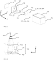
- FIGS. 1A-F show schematically various views and components of an exemplary embodiment of a rotational ball-guided VCM actuator disclosed herein and numbered 100.
- VCM actuator or just “actuator” will replace the term “rotational ball-guided VCM actuator” in the description hereinbelow.
- FIG. 1A shows actuator 100 in an isomeric view
- FIG. 1B shows actuator 100 in an exploded view.
- Actuator 100 allows tilting of an optical path folding element (OPFE) 150 around a single axis (exemplarily and as shown, axis X), as further described below.
- OPFE 150 folds light from a first optical axis (aligned with Z) to a second optical axis (aligned with Y).
- OPFE optical path folding element
- OPFE 150 is exemplarily a prism.
- the OPFE may be, for example, a mirror or a lens.
- Actuator 100 has exemplary length/width/height dimensions in the range of 5-15 mm, i.e. actuator 100 can be contained in a box with dimension of 5x5x5 mm 3 to 15x15x15 mm3. The description continues with reference to a coordinate system XYZ shown in FIGS. 1A and 1B as well as in a number of other figures.
- OPFE 150 may be held in an optical element holder 102, which can be made, for example, by a plastic mold that fits the shape of element OPFE 150.
- a permanent (fixed) magnet 104 is fixedly attached (e.g. glued) to optical element holder 102 from below (negative Z direction in the FIG. 1A ).
- the term "below” used with reference to an OPFE e.g. prism
- OPFE 150, optical element holder 102 and magnet 104 form an "actuated sub-assembly" 106. Actuated sub-assembly 106 is shown from a bottom view in FIG. 1C.
- FIG. 1D shows a cross section of actuator 100 along a line A-A marked in FIG. 1A .
- FIG. 1E shows details of an electro-magnetic (EM) sub-assembly of actuator 100.
- FIG. IF shows a cross section of actuator 100 along a line B-B marked in FIG. 1A .
- Optical element holder 102 includes (i.e. is molded with) two parallel arc-shaped (or "curved") grooves 102a and 102b ( FIG. 1C ) positioned at two opposite sides of holder 102, each arc-shaped groove having an angle ⁇ ' > ⁇ , where angle ⁇ is a required tilt stroke, as defined by optical needs. Angle ⁇ ' is shown in FIG. 1D .
- Arc-shaped grooves 102a and 102b have a center of curvature on a common rotation axis 108 ( FIG. 1D ).
- axis 108 from grooves 102a and 102b is typically 2-15mm. As such axis 108 may pass through (be internal to) OPFE 150 or outside of (be external to) OPFE 150, see also FIG. 1K .
- OIS optical image stabilization
- ⁇ may exemplarily be in the range 0.25° ⁇ ⁇ ⁇ 2°.
- FOV Tele field of view
- ⁇ may exemplarily be in the range 2° ⁇ ⁇ ⁇ 12°.
- ⁇ ' is greater than ⁇ by about 0.5°.
- Actuator 100 further includes a base 110, typically made of plastic.
- Base 110 is also molded with two arc-shaped grooves 110a and 110b positioned at two opposite sides of base 110, each arc-shaped groove ( 110a and 110b ) having an angle ⁇ " > ⁇ .
- Angle ⁇ " is also shown in FIG. 1D .
- ⁇ " is greater than ⁇ by about 0.5°.
- Arc-shaped grooves 110a and 110b also have a center of curvature on axis 108 (FIG. ID).
- Actuated sub-assembly 106 is positioned inside base 110 such that grooves 110a and 110b are parallel to and adjacent to grooves 102a and 102b respectively, and the centers of curvature for each couple of grooves are concentric respectively with axis 108.
- optical element holder 102 and base 110 are preferably plastic-molded (although they may also be made of aluminum or other metals) there is some tolerance allowed in part dimensions, typically up to a few tens of microns for each dimension. This tolerance may lead to misalignment of position between adjacent grooves 102a-110a and/or 102b-110b.
- grooves 102a, 110a and 110b have what is known in the art as a (non-limiting) 'V'-groove cross-section shape to match the balls, while groove 102b has a cross-section which is wider and has a (non-limiting) 'trapezoid' cross-section.
- Grooves 102a and 110a are then aligned during assembly, while grooves 102b and 110b have some alignment freedom allowed by the trapezoid cross section.
- all grooves ( 102a, 102b, 110a, and 110b ) may have a V-shape.
- actuator 100 three balls 112a, 114a and 116a are positioned in the space between grooves 102a and 110a and three balls 112b, 114b and 116b are positioned in the space between grooves 102b and 110b.
- the number of balls (here 3) is exemplary.
- a disclosed VCM actuator may have more or less of three balls (e.g. 2-7 balls) in the space between adjacent grooves.
- the balls are typically made of Alumina or another ceramic material, but may also be made of metal, plastic or other materials.
- the balls have a typical diameter in the range of 0.3-lmm.
- a distance L between grooves 102a,b and grooves 110a,b (and their respective sets of balls) is larger than a width W of OPFE 150, such that the grooves and balls are "outside" of OPFE 150 with respect to the X axis.
- grooves 102a, 102b, 110a, 110b and balls 112a, 112b, 114a, 114b, 116a and 116b form a curved ball-guided mechanism 160 operative to impart a rotation or tilt movement to an optical element (e.g. OPFE 150 ) upon actuation by the VCM actuator (see FIG. 1K )
- an optical element e.g. OPFE 150
- two different ball sizes may be used to provide smoother motion.
- the balls can be divided into a large diameter (LD) group and a small diameter (SD) group.
- the balls in each group have the same diameter.
- LD balls may have for example a 0.1-0.3mm larger diameter than SD balls.
- a SD ball may be positioned between two LD balls to maintain the rolling ability of the mechanism.
- balls 112a and 116a may be LD balls and ball 114a may be a SD ball.
- a metallic ferromagnetic yoke 118 is fixedly attached (e.g. glued) to base 110 from below (negative Z direction in the FIG. 1B ), such that it faces magnet 104.
- the yoke 118 pulls magnet 104 (and thus pulls the actuated sub-assembly 106 ) by magnetic force and thus holds the curved ball-guided mechanism from coming apart.
- the magnetic force is in a direction marked in FIGS. 1A-C as the negative Z direction.
- Balls 112a, 114a and 116a and balls 112b, 114b and 116b prevent actuated sub-assembly 106 from touching the base.
- Actuated sub-assembly 106 is thus confined along the Z-axis and does not move in positive or negative Z directions.
- Curved ball-guided mechanism 160 further confines the actuated sub-assembly along the Y-axis, and thus the actuated sub-assembly can only move along the path defined by the parallel arc-shaped grooves 102a, 102b, 110a and 110b.
- Actuator 100 further includes an EM sub-assembly 120, FIG. 1E .
- Electro-magnetic sub-assembly 120 includes a coil 122, a position sensor, for example a Hall bar element 124 and a printed circuit board (PCB) 126.
- Coil 122 and Hall bar element 124 are preferably soldered (each on its own) to PCB 126.
- Coil 122 has a stadium (oval) shape, and typically has a few tens of windings (e.g. but not limited to 50-250), and a typical resistance of 10-30 ohm.
- PCB 126 allows sending input and output currents to coil 122 and Hall bar element 124. The currents carry both power and electronic signals needed for operation.
- PCB 126 is connected electronically to a camera (e.g. a camera as in FIG. 2 ) which actuator 100 is part of, using wires (not shown).
- Electro-magnetic sub-assembly 120 is positioned between magnet 104 and yoke 118.
- Driving a current in coil 122 creates a Lorentz force: a current in a clockwise direction will create force in the positive Y direction, while a current in counter clockwise direction will create a force in the negative Y direction.
- the full magnetic scheme (e.g. fixed magnet 104 pole direction) is known in the art and described for example in detail in co-owned patent PCT/IB2016/052179 .
- Hall bar element 124 can sense the intensity and direction of the magnetic field of magnet 104.
- Hall bar element 124 changes the relative position of actuated sub-assembly 106 and Hall bar element 124. The intensity and direction of the magnetic field sensed by Hall bar element 124 change as well, and thus the position of actuated sub-assembly 106 can be determined.
- a control circuit is used to control the position of the actuated sub-assembly and to set it to the position required by optical demands.
- the control circuit input is a signal from Hall bar element 124 and the output is the amount of current applied in coil 122.
- the control circuit may be implemented in an integrated circuit (IC). In some cases the IC may be combined with Hall element 124. In other cases, the IC may be a separate chip (not shown), which can be located outside of actuator 100 and of a camera including actuator 100 (e.g. see below embodiment 200 ).
- FIGS. 1G-1J show schematically various views and components of another exemplary embodiment of a VCM actuator disclosed herein and numbered 100'.
- FIG. 1G shows actuator 100 in an isomeric view
- FIG. 1H shows actuator 100 in an exploded view
- FIG. 1I shows details of an actuated sub-assembly 106' in the actuator of FIG. 1G
- FIG. 1J shows a cross section of the VCM actuator along a line B-B marked in FIG. 1G .
- Actuator 100' is similar to actuator 100 in structure (and therefore similar elements/components are not numbered and/or described) and function except for a few differences: a) actuator 100' includes three V-shaped grooves and one flat groove, i.e.
- actuator 100' optical element holder 102 is replaced by an optical element holder 102' in which groove 102b' is flat; b) in actuator 100', a distance L' between grooves 102a,b and grooves 110a,b (and their respective sets of balls) is equal to or smaller than a width W' of OPFE 150, such that the grooves and balls are "below” OPFE 150.
- actuator 100' includes an added component, a shield 140, which protect it from drops, hits, dust and stray light.
- the shape and dimensions of shield 140 are such as to minimally affect the size of the actuator.
- actuator 100 may also be provided for actuator 100.
- actuator 100' also includes an enclosure 142 (normally made of plastic) to protect the actuator against environmental and other factors.
- PCB 126' has the same function as PCB 126 in actuator 100.
- a curved ball-guided mechanism in actuator 100' includes essentially the same components as in actuator 100.
- FIG. 1K shows in addition to shape embodiments "a” and “b” (axis 108 external or internal to OPFE 150, with both grooves 102 and 110 of a pair curved "downwards", i.e.
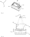
- FIG. 2 shows actuator 100 coupled to folded camera structure (FCS) or simply "folded camera” 200.
- an actuator such as 100 (or 100 ') serves for example to rotate a light folding element, for example prism 150.
- Actuation by actuator 100 in folded camera 200 can be used, for example, to create optical image stabilization (OIS) as described in PCT/IB2016/052179 or to create an extended field of view, as described for example in PCT/IB2016/057366 .
- a typical rotational stroke ⁇ in this case may be in the range of ⁇ 0.5 to ⁇ 2 degrees or ⁇ 2 to ⁇ 12 degrees of the original position of prism 150 respectively.
- Camera 200 further includes a lens element 202 and an image sensor 204.
- Folded camera 200 may further be coupled to or include actuation mechanisms to actuate lens element 204 for AF and ⁇ or OIS, for example described in PCT/IB2016/052179 .
- the actuation mechanisms (and actuations) of lens 204 are independent of those of actuator 100 and are not shown in FIG. 2 .
- the actuation mechanisms (and actuations) of lens 204 may be based on a VCM actuator with mechanical rails based on springs (as in PCT/IB2016/052179 ) or with mechanical rails based on a ball-guided mechanism.
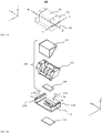
- FIGS. 3A-D shows schematically various views and components of another exemplary embodiment of a VCM actuator disclosed herein and numbered 300.
- FIG. 3A shows actuator 300 in an isomeric view
- FIG. 3B shows actuator 300 in an exploded view.
- an OPFE 350 is exemplarily a prism.
- OPFE 350 is held in an optical element holder 302.
- a permanent magnet 304 is fixedly attached (e.g. glued) to optical element holder 302.
- OPFE 350, optical element holder 302 and magnet 304 form a "top actuated sub-assembly" 306.
- Optical element holder 302 includes (e.g. is molded with) two parallel arc-shaped grooves 302a and 302b positioned at two opposite sides of holder 302, each arc-shaped groove having an angle ⁇ ' > ⁇ , where angle ⁇ is a required rotational stroke, as defined by optical needs. Angles ⁇ ' and ⁇ " are not shown, but its definition is similar to that of angles ⁇ ' and ⁇ " in FIG. 1D . Exemplary values and ranges for ⁇ , ⁇ ' and ⁇ " are similar to those for ⁇ , ⁇ ' and ⁇ " above. Top actuated sub-assembly 306 and its parts are similar to actuated sub-assembly 106 in terms of materials, dimensions, etc.
- Actuator 300 further includes a middle base 310, typically made of plastic.
- Middle base 310 is also molded with two grooves 310a and 310b.
- Top-actuated sub-assembly 306 is positioned inside middle base 310 such that grooves 310a and 310b are parallel to grooves 302a and 302b respectively.
- grooves 302b, 310a and 310b have V-groove shape, while groove 302a has a trapezoid shape; the considerations for these shapes was given above in the description of actuator 100.
- Three balls 312a, 314a and 316a are positioned between grooves 302a and 310a, and, similarly, three balls 312b, 314b and 316b are positioned between grooves 302b and 310b.
- actuator 300 may have more or less than 3 balls in each groove, typically in the range of 2-7 balls. Considerations for size and materials of all balls are similar to those described in actuator 100.
- Middle base 310 further includes two more arc-shaped grooves 310c and 310d on a single circle 320, as seen in FIG. 3C .
- Top actuated sub-assembly 306, balls 312a-314a, 312b-314b and middle base 310 form a bottom actuated sub-assembly 334.
- the diameter of circle 320 may exemplarily be in the range of 5-15mm.
- Grooves 302a, 302b, 310a, 310b and balls 312a, 312b, 314a, 314b, 316a and 316b form a first curved ball-guided mechanism 360 of actuator 300.
- Actuator 300 further includes a bottom base 308.
- Bottom base 308 is typically made of plastic, and is molded with two arc-shaped grooves 308c and 308d. Arc-shaped grooves 308c and 308d are on circle 320 with a center on an axis 321, as can be seen in FIG. 3C .
- Bottom actuated sub-assembly 334 is positioned above bottom base 308 such that grooves 310c and 310d are parallel to grooves 308c and 308d respectively.
- grooves 310c, 308c, 308d have V-groove shape, while groove 310d has a trapezoid shape; the considerations for these shapes were given above in the description of actuator 100.
- actuator 300 may have more or less of 3 balls in each groove, typically in the range of 2-7. The considerations for size and materials of all balls are similar to those described in actuator 100.
- Grooves 308c, 308d, 310c, 310d and balls 312c, 312d, 314c, 314d, 316c and 316d form a second curved ball-guided mechanism 362 of actuator 300.
- a metallic yoke 318 is fixedly attached (e.g. glued) to bottom base 308 from below, such that it faces magnet 304.
- Metallic yoke 318 pulls magnet 304 (and thus pulls top actuated sub-assembly 306 ) by magnetic force and thus holds the two curved ball-guided mechanisms ( 360 and 362 ) from coming apart.
- the magnetic force is in direction marked in FIGS. 1 as the negative Z direction.
- Balls 312a, 314a and 316a and 312b, 314b and 316b prevent top actuated sub-assembly 306 from touching middle base 310, and balls 312c, 314c and 316c and 312d, 314d and 316d prevent bottom actuated sub-assembly 334 from touching bottom base 308.
- Top actuated sub-assembly 306 is thus confined along the Z-axis and does not move in positive or negative Z directions.
- First curved ball-guided mechanism 360 further confines top actuated sub-assembly 306 along the Y-axis, and thus top actuated sub-assembly 306 can only move along the path defined by the parallel arcs 302a, 302b, 310a and 310b.
- Bottom actuated sub-assembly 334 is confined along the Z-axis and does not move in positive or negative Z directions.
- Second curved ball-guided mechanism 362 further confines bottom actuated sub-assembly 334 to move only in a rotational manner around circle 320 (rotation around the Z-axis). The typical magnitude/angle of this rotation (in degrees) is similar to that of ⁇ above.
- Magnet 304 acts on both curved ball-guiding mechanism.
- Actuator 300 further includes an electro-magnetic sub-assembly 330, shown in FIG. 3D .
- Electro-magnetic sub-assembly 330 includes two coils 322 and 324, two Hall bar elements 326 and 328 and a printed circuit board (PCB) 329.
- Coils 322, 324 and Hall bar elements 326, 328 are soldered (each one on its own) to PCB 329.
- Coils 322, 324 have a stadium shape, typically with a few tens of windings (for example, in a non-limiting range of 50-250), with a typical resistance 10-30 ohm each.
- PCB 329 allows sending input and output currents to coils 322, 324 and to Hall bar elements 326, 328, currents carrying both power and electronic signals needed for operation.
- PCB 329 is connected electronically to the external camera with wires not seen in FIGS. 3 .
- Electro-magnetic sub-assembly 330 is positioned between magnet 304 and yoke 318. Upon driving current in coils 322, 324 a Lorentz force is created; a current in a clockwise direction will create force in the positive Y direction while a current in a counter clockwise direction will create a force in the negative Y direction.
- the full magnetic scheme e.g. fixed magnet 304 pole direction
- the Lorentz force is also translated to clockwise (counter clockwise) torque around Z axis on bottom actuated sub-assembly 334.
- top actuated sub-assembly 306 is confined by the first curved ball-guided mechanism to move along an arc parallel to grooves 302a, 302b, 310a and 310b (i.e. rotate around the X axis).
- bottom actuated sub-assembly 334 is confined by the second curved ball-guided mechanism to move around circle 320 (i.e.
- Hall bar elements 326, 328 can sense the intensity and direction of the magnetic field of magnet 304. Upon actuation, the position of top actuated sub-assembly 306, bottom actuated sub-assembly 334 and Hall bar elements 326, 328 is changed, and with it changes the intensity and direction of the magnetic field sensed.
- V HB-326 and V HB-328 the Hall output voltage of both sensors, which is proportional to the magnetic field sensed by each Hall sensor, as known in the art.
- the amount of rotation of top actuated sub-assembly 306 and bottom actuated sub-assembly 334 can be determined.
- the sum V HB-326 + V HB-328 is proportional to the amount of tilt around the first rotation axis and the difference V HB-326 - V HB-328 is proportional to the amount of tilt around the second rotation axis.
- a control circuit is used to control the position of the actuated sub-assembly and to set it to the position required by optical demands.
- the control circuit input includes signals of Hall bar elements 326, 328 and the output includes the amount of current applied in coils 322, 324.
- the control circuit may be implemented in an integrated circuit (IC). In some cases, the IC may be combined with one of Hall elements 326, 328. In other cases, the IC is a separate chip, which can be located outside of the camera (not shown).
- FIG. 4 shows actuator 300 as part of a folded camera 400.
- actuator 300 serves for example to rotate an optical path folding element (OPFE) to create optical image stabilization in two directions, as described for example in US provisional patent application 62/215,007 .
- Folded camera 400 further includes a lens element 402 and an image sensor 404.
- a typical actuation stroke in this case may be in the range of ⁇ 0.5 to ⁇ 2 degrees around the X axis and ⁇ 1 to ⁇ 3 degrees around the Z axis of the original position of the light-folding element (e.g. prism 450 ) for both rotation directions.
- OPFE optical path folding element
- Folded camera 400 may further include an actuation mechanism (not shown) for lens element 402 as known in the art (for example described in PCT/IB2016/052179 ) for AF and/or OIS.
- the actuation mechanism of lens 402 is not dependent on the actuation done in actuator 300.
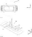
- FIGS. 5A-5D show schematically various views and components of another exemplary embodiment of a VCM actuator disclosed herein and numbered 500.
- FIG. 5A shows an isomeric view of an assembled actuator 500
- FIGS 5B , 5C show an exploded view of actuator 500 from two opposite directions along the X-axis.
- FIG. 5D shows a cross section of actuator 500 along a line A-A marked in FIG. 5A .
- Actuator 500 allows the rotation of an OPFE 550 around a single axis (i.e. around the X-axis) as described below.
- OPFE 550 is a prism while in other embodiments it may a mirror or another type of optical path bending element.
- OPFE 550 is held in an OPFE holder 502, which can be made, for example by plastic mold, fitting the shape of OPFE 550.
- An actuation magnet 504 and a sensing magnet 506 are fixedly attached (e.g. glued) to optical element holder 502 from the side, in the same direction as an axis of rotation of OPFE 550 (the negative X direction in the figures).
- the assembly of OPFE 550, optical element holder 502 and magnets 504, 506 is referred to as "actuated sub-assembly" 510, shown from the side in FIG. 5D .
- Optical element holder 502 is molded with two arc-shaped grooves, 502a and 502b.
- Arcs 502a and 502b are concentric with each other, having a common center of rotation on an axis 508.
- Arc-shaped grooves 502a and 502b have respective angles ⁇ ' and ⁇ " fulfilling ⁇ '> ⁇ and ⁇ "> ⁇ , where angle ⁇ is the required rotational stroke, as defined by optical needs.
- the center of rotation axis 508 and angles ⁇ ', ⁇ " are seen in FIG. 5D .
- the typical values for ⁇ , ⁇ ' and ⁇ " are similar to those for ⁇ , ⁇ ' and ⁇ ".
- Actuator 500 further includes a sidewall 514.
- Sidewall 514 is a stationary part and is fixed rigidly to the actuator frame (not shown) and to the camera image sensor.
- Sidewall 514 is typically made of plastic.
- sidewall 514 may be a part of the entire actuator's frame (known in the art as 'base').
- Sidewall 514 may be molded as a single piece of plastic which serves for the purposes described below, as well as other purposes needed for the camera which actuator 500 is part of (e.g. holding the lens or holding the image sensor).
- Sidewall 514 is also molded with two arc-shaped grooves 514a and 514b.
- Actuated sub-assembly 510 is positioned alongside sidewall 514 such that grooves 514a and 514b are parallel to grooves 502a and 502b respectively.
- grooves 502b, 514a and 514b have V-groove shape, while groove 502a has a trapezoid shape; the considerations for these shapes was given above in the description of actuator 100.
- actuator 500 may have more or less than 3 balls in each groove, typically in the range of 2-7 balls. Consideration for size and materials of all balls is similar to the described in actuator 100..
- the two pairs of grooves and their associated balls form a curved ball-guided mechanism 560 of actuator 500.
- a metallic ferromagnetic yoke 518 is fixedly attached (e.g. glued) to sidewall 514 from a side opposite to those of magnets 504, 506 such that it faces magnet 504.
- Yoke 518 pulls magnet 504 (and thus pulls the actuated sub-assembly 510 ) by magnetic force and thus holds the curved ball-guided mechanism from coming apart.
- the magnetic force is in direction marked in FIG. 5A as the negative X direction.
- Balls 512a, 514a and 516a and 512b, 514b and 516b prevent actuated sub-assembly 510 from touching sidewall 514.
- Actuated sub-assembly 510 is thus confined along the X-axis and does not move in positive or negative X directions.
- Curved ball-guided mechanism 560 further confines the actuated sub-assembly 510 along other directions such that actuated sub-assembly can only move along the path defined by the parallel arcs 502a, 502b, 514a and 514b
- Actuator 500 further includes an electro-magnetic sub-assembly 530, shown in FIG. 5E .
- Electro-magnetic sub-assembly 530 includes a coil 522, a Hall bar element 524 and a PCB 526. Coil 522 and Hall bar element 524 are soldered (each one by its own) to the PCB. Coil 522 has a stadium shape, typically has few tens of winding (not limiting range of 50-250), with a typical resistance of 10-30 ohm.
- PCB 526 allows sending input and output currents to coil 522 and Hall bar element 524, currents carrying both power and electronic signals needed for operation. PCB 526 is connected electronically to the external camera with wires (not shown).
- Electro-magnetic sub-assembly 530 is positioned between the magnets 504, 506 and yoke 518 such that there is an air-gap of typically about 100-200 ⁇ m between the magnets and the electro-magnetic sub-assembly (the Hall bar element, coil and magnets do not touch each other).
- a Lorentz force is created: a current in a clockwise direction will create force in the positive Y direction while a current in counter clockwise direction will create a force in the negative Y direction.
- the full magnetic scheme (e.g. the fixed magnet 504 pole direction) is known in the art, and described for example in detail in co-owned patent PCT/IB2016/052179 .
- Hall bar element 524 can sense the intensity and direction of the magnetic field of sensing magnet 506.
- Hall bar element 524 changes as well and thus the position of actuated sub-assembly 510 can be determined.
- a control circuit is used to control the position of the actuated sub-assembly and set to the position required by optical demands.
- the control circuit input is a signal from Hall bar element 524 and the output is the amount of current applied in coil 522.
- the control circuit may be implemented in an IC. In some cases, the IC may be combined with Hall element 524. In other cases, it is a separate chip, which can be located outside of the camera (not shown).
- the sensing magnet 506 can be removed and the Hall bar element 524 can be placed in the center of the coil so the actuation magnet 504 can be used for both actuation and sensing (as described for example above with reference to FIG IE).
- sensing magnet 506 and actuation magnet 504 may be combined into one magnet with the suitable magnetization to allow the sensing and actuating functionality described above.
- FIG. 6 shows actuator 500 as part of a folded camera 600.
- actuator 500 serves as an example of usage to rotate a light folding element, for example prism 550.
- Actuation by actuator 500 in camera 600 can be used, for example, to create OIS as described in PCT/IB2016/052179 .
- Camera 600 further includes a lens element 602 and an image sensor 604.
- a typical actuation stroke ⁇ in this case should be in the range of ⁇ 0.5 to ⁇ 2 degrees of the original position of prism 550.
- camera 600 may further include actuation mechanisms to actuate lens element 602 for AF and ⁇ or OIS (not shown).
- any of the actuators disclosed above may be included in a folded camera which in turn may be included together with an upright (non-folded) camera in a dual-aperture camera with folded lens, for example as described in co-owned US patent 9392188 .
Abstract
Description
- This application claims priority from
US Provisional Patent Applications No. 62/343,011 filed 05/30/2016 62/353,278 filed 06/22/2016 - Embodiments disclosed herein relate in general to actuating mechanisms ("actuators") and in particular to voice coil motor (VCM) actuators for digital cameras.
- High-end digital camera modules, and specifically cellphone (e.g. smartphone) digital cameras include mechanisms that enable advanced optical function such as focus or optical image stabilization (OIS). Such mechanisms may actuate (e.g. displace, shift or tilt) an optical element (e.g. lens, image sensor, mirror) to create the desired optical function. A commonly used actuator is based on voice coil motor (VCM) technology. In VCM technology, a fixed (or permanent) magnet and a coil are used to create actuation force. The coil is positioned in the vicinity of the magnetic field of the fixed magnet. Upon driving current in the coil, a Lorentz force is created on the coil, an in return an equal counter-force is applied on the magnet. The magnet or the coil is rigidly attached to an optical element to construct an actuated assembly. The actuated assembly is then moved by the magnetic Lorenz force. Henceforth, the term VCM may be used to also refer to "VCM actuator".
- In addition to the magnetic force, a mechanical rail is used to set the course of motion for the optical element. The mechanical rail keeps the motion of the optical element in a desired path, as required by optical needs. A typical mechanical rail is known in the art as "spring-guided rail", in which a spring or set of springs is used to set the motion direction. A VCM that includes a spring-guided rail is referred to as "spring-guided VCM". For example,
US patent application 20110235196 discloses a lens element being shifted in a linear spring rail to create focus. For example, international patent applicationPCT/IB2016/052179 discloses the incorporation and use of a spring guided VCM in a folded camera structure (FCS). The disclosure teaches a lens element being shifted to create focus and OIS and a light folding element being shifted in a rotational manner to create OIS. - Another typical mechanical rail is known in the art a "ball-guided rail", see e.g.
US patent 8810714 . With a ball-guided rail, the optical element is bound to move in the desired direction by set of balls confined in a groove (also referred to as "slit"). A VCM that includes a ball-guided rail is referred to as a "ball-guided VCM". A ball-guided VCM has several advantages over a spring-guided VCM. These include: (1) lower power consumption, because in a spring-guided VCM the magnetic force has to oppose a spring mechanical force, which does not exist in a ball-guided VCM, and (2) higher reliability in drops which may occur during the life-cycle of a camera that includes the VCM. - While the actuation method showed in
US patent 8810714 allows linear motion only, in some cases there is a need to create angular motion as well, for example to rotate (tilt) a light folding element (mirror or prism) in order to create OIS as described inPCT/IB2016/052179 . Therefore there is a need for, and it would be advantages to have, a rotational ball-guided VCM, i.e. a ball-guided VCM that can cause rotation (tilt) of an optical element. - Aspects of embodiments disclosed herein relate to VCM actuators having curved ball-guided mechanisms, and to digital cameras, and in particular cameras with folded optics that incorporate VCMs.
- In some exemplary embodiments there is provided an actuator for rotating or tilting an optical element, comprising a first VCM and a first curved ball-guided mechanism operative to create a rotation or tilt movement of the optical element around a first rotation axis upon actuation by the VCM.
- In an embodiment, the first VCM includes a coil mechanically coupled to a static base and a fixed magnet mechanically coupled to a holder for holding the optical element, and the rotation or tilt movement is created by a current passing through the coil.
- In an embodiment, an actuator further comprises a ferromagnetic yoke attached to the static base and used to pull the fixed magnet in order to prevent the first curved ball-guided mechanism from coming apart.
- In an embodiment, the first ball-guided mechanism includes a pair of grooves having a plurality of balls located therebetween, wherein at least one of the grooves in the pair has a curvature defined by a radius that starts at a center of curvature which lies on the rotation axis.
- In an embodiment, the optical element includes an optical path folding element (OPFE) that folds light from a first optical axis to a second optical axis. The OPFE may be exemplarily a prism or a mirror.
- In an embodiment, the first rotation axis includes an axis perpendicular to both the first optical axis and the second optical axis.
- In an embodiment, the first rotation axis includes an axis combining the second optical axis and an axis perpendicular to both the first optical axis and the second optical axis.
- In an embodiment, the first curved ball-guided mechanism is positioned below the OPFE.
- In an embodiment, the fixed magnet and the coil are positioned below the OPFE.
- In an embodiment, the fixed magnet and the coil are positioned on a side of the OPFE in a plane parallel to a plane that includes both the first axis and the second optical axis.
- In an embodiment, an actuator further comprises a position sensor for measuring an angle of the optical element relative to the static base.
- In an embodiment, the position sensor is a Hall bar position sensor operative to measure the magnetic field of the fixed magnet.
- In some embodiments, an actuator further comprises a second VCM and a second curved ball-guided mechanism operative to create a rotation or tilt movement of the optical element around a second rotation axis upon actuation by the second VCM, wherein the first rotation axis and the second rotation axis are not parallel.
- In an embodiment, the first rotation axis and the second rotation axis are substantially orthogonal to each other.
- In an embodiment, the first VCM includes a first coil mechanically coupled to a static base and a first fixed magnet mechanically coupled to a holder for holding the optical element, wherein the second VCM includes a second coil mechanically coupled to a static base and a second fixed magnet mechanically coupled to a holder for holding the optical element, and wherein the first rotation or tilt movement and the second rotation or tilt movement are created by a combination of currents passing through the first coil and the second coil.
- In an embodiment, the first and second magnets are unified as a single magnet.
- In an embodiment, an actuator further comprises a ferromagnetic yoke attached to the static base and used to pull the fixed magnet in order to prevent the first curved ball-guided mechanism and the second curved ball-guided mechanism from coming apart.
- In an embodiment, the optical element includes an optical path folding element (OPFE) that folds light from a first optical axis to a second optical axis.
- In an embodiment, the first rotation axis includes an axis perpendicular to both the first optical axis and the second optical axis, and the second rotation axis includes an axis parallel to either the first optical axis or the second optical axis
- In an embodiment, an actuator further comprises a first position sensor and a second position sensor, wherein a combination of two position measurements allows determination of the position of the optical element holder relative to the static base with respect to both the first rotation axis and the second rotation axis.
- In an embodiment, the center of curvature resides inside the optical element.
- In an embodiment, the center of curvature resides outside the optical element.
- In some exemplary embodiments, there are provides cameras comprising an actuator described above and below.
- In some camera embodiments, the rotation or tilt movement is for allowing optical image stabilization.
- In some camera embodiments, the rotation or tilt movement is for allowing extended field of view scanning.
- Non-limiting examples of embodiments disclosed herein are described below with reference to figures attached hereto that are listed following this paragraph. The drawings and descriptions are meant to illuminate and clarify embodiments disclosed herein, and should not be considered limiting in any way.
-
FIG. 1A shows an embodiment of a rotational ball-guided VCM actuator disclosed herein in an isomeric view; -
FIG. 1B shows the VCM actuator ofFIG. 1A in an exploded view; -
FIG. 1C shows a bottom view of an actuated sub-assembly in the VCM actuator ofFIG. 1A ; -
FIG. 1D shows a cross section of the VCM actuator along a line A-A marked inFIG. 1A ; -
FIG. 1E shows details of an electro-magnetic sub-assembly in the VCM actuator ofFIG. 1A ; - FIG. IF shows a cross section of the VCM actuator along a line B-B marked in
FIG. 1A ; -
FIG. 1G shows another embodiment of a rotational ball-guided VCM actuator disclosed herein in an isomeric view; -
FIG. 1H shows the VCM actuator ofFIG. 1G in an exploded view; -
FIG. 1I shows details of an actuated sub-assembly in the actuator ofFIG. 1G ; -
FIG. 1J shows a cross section of the VCM actuator along a line B-B marked inFIG. 1G ; -
FIG. 1K shows schematically in a side view alternative embodiments of groove pairs; -
FIG. 2 shows the actuator ofFIGS. 1A-1F , coupled to a folded camera; -
FIG. 3A shows yet another embodiment of a rotational ball-guided VCM actuator disclosed herein in an isomeric view; -
FIG. 3B shows the VCM actuator ofFIG. 3A in an exploded view; -
FIG. 3C shows details of a middle base of the VCM actuator ofFIGS. 3A and3B ; -
FIG. 3D shows details of an electro-magnetic sub-assembly in the VCM actuator ofFIGS. 3A and3B ; -
FIG. 4 shows the actuator ofFIGS. 3A-3C , coupled to a folded camera; -
FIG. 5A shows yet another embodiment of a rotational ball-guided VCM actuator disclosed herein in an isomeric view; -
FIG. 5B shows the VCM actuator ofFIG. 2A in an exploded view from one side; -
FIG. 5C shows the VCM actuator ofFIG. 2A in an exploded view from another side; -
FIG. 5D shows a cross section of the VCM actuator along a line A-A marked inFIG. 5A ; -
FIG. 5E shows details of an electro-magnetic sub-assembly in the VCM actuator ofFIG. 5A ; -
FIG. 6 shows the actuator ofFIGS. 5A-5E , coupled to a folded camera; -
FIGS. 1A-F show schematically various views and components of an exemplary embodiment of a rotational ball-guided VCM actuator disclosed herein and numbered 100. For simplicity, the term "VCM actuator" or just "actuator" will replace the term "rotational ball-guided VCM actuator" in the description hereinbelow.FIG. 1A shows actuator 100 in an isomeric view andFIG. 1B showsactuator 100 in an exploded view.Actuator 100 allows tilting of an optical path folding element (OPFE) 150 around a single axis (exemplarily and as shown, axis X), as further described below.OPFE 150 folds light from a first optical axis (aligned with Z) to a second optical axis (aligned with Y). InFIGS. 1A, 1B ,OPFE 150 is exemplarily a prism. In other embodiments, the OPFE may be, for example, a mirror or a lens.Actuator 100 has exemplary length/width/height dimensions in the range of 5-15 mm, i.e. actuator 100 can be contained in a box with dimension of 5x5x5 mm3 to 15x15x15 mm3. The description continues with reference to a coordinate system XYZ shown inFIGS. 1A and 1B as well as in a number of other figures. - In
actuator 100,OPFE 150 may be held in anoptical element holder 102, which can be made, for example, by a plastic mold that fits the shape ofelement OPFE 150. A permanent (fixed)magnet 104 is fixedly attached (e.g. glued) tooptical element holder 102 from below (negative Z direction in theFIG. 1A ). Hereinafter, the term "below" used with reference to an OPFE (e.g. prism) will refer to a side of the OPFE opposite to the side receiving light along the first optical axis.OPFE 150,optical element holder 102 andmagnet 104 form an "actuated sub-assembly" 106. Actuatedsub-assembly 106 is shown from a bottom view inFIG. 1C. FIG. 1D shows a cross section ofactuator 100 along a line A-A marked inFIG. 1A .FIG. 1E shows details of an electro-magnetic (EM) sub-assembly ofactuator 100. FIG. IF shows a cross section ofactuator 100 along a line B-B marked inFIG. 1A .Optical element holder 102 includes (i.e. is molded with) two parallel arc-shaped (or "curved")grooves FIG. 1C ) positioned at two opposite sides ofholder 102, each arc-shaped groove having an angle α' > α, where angle α is a required tilt stroke, as defined by optical needs. Angle α' is shown inFIG. 1D . Arc-shapedgrooves FIG. 1D ). - The distance of
axis 108 fromgrooves such axis 108 may pass through (be internal to)OPFE 150 or outside of (be external to)OPFE 150, see alsoFIG. 1K . For optical image stabilization (OIS), α may exemplarily be in the range 0.25°< α < 2°. To obtain an adjustable extended Tele field of view (FOV) in a dual-aperture zoom digital camera such as that described in co-ownedUS Provisional patent application No. 62/272367 -
Actuator 100 further includes abase 110, typically made of plastic.Base 110 is also molded with two arc-shapedgrooves base 110, each arc-shaped groove (110a and 110b) having an angle α" > α. Angle α" is also shown inFIG. 1D . Typically, α" is greater than α by about 0.5°. Arc-shapedgrooves sub-assembly 106 is positioned insidebase 110 such thatgrooves grooves axis 108. - Since
optical element holder 102 andbase 110 are preferably plastic-molded (although they may also be made of aluminum or other metals) there is some tolerance allowed in part dimensions, typically up to a few tens of microns for each dimension. This tolerance may lead to misalignment of position betweenadjacent grooves 102a-110a and/or 102b-110b. In the embodiment shown and for better alignment,grooves groove 102b has a cross-section which is wider and has a (non-limiting) 'trapezoid' cross-section.Grooves grooves - In
actuator 100, threeballs grooves balls grooves actuator 100, a distance L betweengrooves 102a,b andgrooves 110a,b (and their respective sets of balls) is larger than a width W ofOPFE 150, such that the grooves and balls are "outside" ofOPFE 150 with respect to the X axis. - In
actuator 100,grooves balls mechanism 160 operative to impart a rotation or tilt movement to an optical element (e.g. OPFE 150) upon actuation by the VCM actuator (seeFIG. 1K ) - In some embodiments, two different ball sizes may be used to provide smoother motion. The balls can be divided into a large diameter (LD) group and a small diameter (SD) group. The balls in each group have the same diameter. LD balls may have for example a 0.1-0.3mm larger diameter than SD balls. A SD ball may be positioned between two LD balls to maintain the rolling ability of the mechanism. For example, in an embodiment,
balls ball 114a may be a SD ball. - A metallic
ferromagnetic yoke 118 is fixedly attached (e.g. glued) tobase 110 from below (negative Z direction in theFIG. 1B ), such that it facesmagnet 104. Theyoke 118 pulls magnet 104 (and thus pulls the actuated sub-assembly 106) by magnetic force and thus holds the curved ball-guided mechanism from coming apart. The magnetic force is in a direction marked inFIGS. 1A-C as the negative Z direction.Balls balls sub-assembly 106 is thus confined along the Z-axis and does not move in positive or negative Z directions. Curved ball-guidedmechanism 160 further confines the actuated sub-assembly along the Y-axis, and thus the actuated sub-assembly can only move along the path defined by the parallel arc-shapedgrooves -
Actuator 100 further includes anEM sub-assembly 120,FIG. 1E . Electro-magnetic sub-assembly 120 includes acoil 122, a position sensor, for example aHall bar element 124 and a printed circuit board (PCB) 126.Coil 122 andHall bar element 124 are preferably soldered (each on its own) toPCB 126.Coil 122 has a stadium (oval) shape, and typically has a few tens of windings (e.g. but not limited to 50-250), and a typical resistance of 10-30 ohm.PCB 126 allows sending input and output currents tocoil 122 andHall bar element 124. The currents carry both power and electronic signals needed for operation.PCB 126 is connected electronically to a camera (e.g. a camera as inFIG. 2 ) which actuator 100 is part of, using wires (not shown). Electro-magnetic sub-assembly 120 is positioned betweenmagnet 104 andyoke 118. Driving a current incoil 122 creates a Lorentz force: a current in a clockwise direction will create force in the positive Y direction, while a current in counter clockwise direction will create a force in the negative Y direction. The full magnetic scheme (e.g. fixedmagnet 104 pole direction) is known in the art and described for example in detail in co-owned patentPCT/IB2016/052179 . - While magnetic force applied by the electro-magnetic sub-assembly is in the positive and negative Y directions, the rail formed by the balls and grooves cause confined actuated sub-assembly 104 to move along an arc parallel to
grooves Hall bar element 124 can sense the intensity and direction of the magnetic field ofmagnet 104. Upon actuation, the relative position of actuatedsub-assembly 106 andHall bar element 124 is changed. The intensity and direction of the magnetic field sensed byHall bar element 124 change as well, and thus the position of actuatedsub-assembly 106 can be determined. - A control circuit is used to control the position of the actuated sub-assembly and to set it to the position required by optical demands. The control circuit input is a signal from
Hall bar element 124 and the output is the amount of current applied incoil 122. The control circuit may be implemented in an integrated circuit (IC). In some cases the IC may be combined withHall element 124. In other cases, the IC may be a separate chip (not shown), which can be located outside ofactuator 100 and of a camera including actuator 100 (e.g. see below embodiment 200). -
FIGS. 1G-1J show schematically various views and components of another exemplary embodiment of a VCM actuator disclosed herein and numbered 100'.FIG. 1G showsactuator 100 in an isomeric view,FIG. 1H showsactuator 100 in an exploded view,FIG. 1I shows details of an actuated sub-assembly 106' in the actuator ofFIG. 1G , andFIG. 1J shows a cross section of the VCM actuator along a line B-B marked inFIG. 1G . Actuator 100' is similar toactuator 100 in structure (and therefore similar elements/components are not numbered and/or described) and function except for a few differences: a) actuator 100' includes three V-shaped grooves and one flat groove, i.e. exemplarily, in actuator 100'optical element holder 102 is replaced by an optical element holder 102' in whichgroove 102b' is flat; b) in actuator 100', a distance L' betweengrooves 102a,b andgrooves 110a,b (and their respective sets of balls) is equal to or smaller than a width W' ofOPFE 150, such that the grooves and balls are "below"OPFE 150. Thus, at least one dimension (width) and consequently the size of actuator 100' is smaller than that ofactuator 100; and c) actuator 100' includes an added component, ashield 140, which protect it from drops, hits, dust and stray light. The shape and dimensions ofshield 140 are such as to minimally affect the size of the actuator. The shape and details shown are exemplary. Optionally, a shield such ashield 140 may also be provided foractuator 100. Further and optionally actuator 100' also includes an enclosure 142 (normally made of plastic) to protect the actuator against environmental and other factors. PCB 126' has the same function asPCB 126 inactuator 100. A curved ball-guided mechanism in actuator 100' includes essentially the same components as inactuator 100. - The shape of the grooves in a curved ball-guided mechanism disclosed in
actuators 100 and 100' is exemplary, and other shapes are possible, as indicated inFIG. 1K. FIG. 1K shows in addition to shape embodiments "a" and "b" (axis 108 external or internal toOPFE 150, with bothgrooves groove 102 is curved downwards and agroove 110 is straight (linear), a shape embodiment in "d" in which bothgrooves grooves 102 are straight andgrooves 110 are curved upwards. -
FIG. 2 shows actuator 100 coupled to folded camera structure (FCS) or simply "folded camera" 200. In foldedcamera 200, an actuator such as 100 (or 100') serves for example to rotate a light folding element, forexample prism 150. For simplicity, the description continues with reference toactuator 100, with the understanding that it applies equally well to actuator 100'. Actuation byactuator 100 in foldedcamera 200 can be used, for example, to create optical image stabilization (OIS) as described inPCT/IB2016/052179 or to create an extended field of view, as described for example inPCT/IB2016/057366 . A typical rotational stroke α in this case may be in the range of ±0.5 to ±2 degrees or ±2 to ±12 degrees of the original position ofprism 150 respectively.Camera 200 further includes alens element 202 and animage sensor 204. - Folded
camera 200 may further be coupled to or include actuation mechanisms to actuatelens element 204 for AF and\or OIS, for example described inPCT/IB2016/052179 . The actuation mechanisms (and actuations) oflens 204 are independent of those ofactuator 100 and are not shown inFIG. 2 . The actuation mechanisms (and actuations) oflens 204 may be based on a VCM actuator with mechanical rails based on springs (as inPCT/IB2016/052179 ) or with mechanical rails based on a ball-guided mechanism. -
FIGS. 3A-D shows schematically various views and components of another exemplary embodiment of a VCM actuator disclosed herein and numbered 300.FIG. 3A shows actuator 300 in an isomeric view andFIG. 3B showsactuator 300 in an exploded view. As inactuator 100, inactuator 300 anOPFE 350 is exemplarily a prism.OPFE 350 is held in anoptical element holder 302. Apermanent magnet 304 is fixedly attached (e.g. glued) tooptical element holder 302.OPFE 350,optical element holder 302 andmagnet 304 form a "top actuated sub-assembly" 306. -
Optical element holder 302 includes (e.g. is molded with) two parallel arc-shapedgrooves holder 302, each arc-shaped groove having an angle β' > β, where angle β is a required rotational stroke, as defined by optical needs. Angles β' and β" are not shown, but its definition is similar to that of angles α' and α" inFIG. 1D . Exemplary values and ranges for β, β' and β" are similar to those for α, α' and α" above. Top actuated sub-assembly 306 and its parts are similar to actuated sub-assembly 106 in terms of materials, dimensions, etc. -
Actuator 300 further includes amiddle base 310, typically made of plastic.Middle base 310 is also molded with twogrooves sub-assembly 306 is positioned insidemiddle base 310 such thatgrooves grooves grooves groove 302a has a trapezoid shape; the considerations for these shapes was given above in the description ofactuator 100. Threeballs grooves balls grooves actuator 300 may have more or less than 3 balls in each groove, typically in the range of 2-7 balls. Considerations for size and materials of all balls are similar to those described inactuator 100.Middle base 310 further includes two more arc-shapedgrooves single circle 320, as seen inFIG. 3C . Top actuated sub-assembly 306,balls 312a-314a, 312b-314b andmiddle base 310 form a bottom actuatedsub-assembly 334. The diameter ofcircle 320 may exemplarily be in the range of 5-15mm.Grooves balls mechanism 360 ofactuator 300. -
Actuator 300 further includes abottom base 308.Bottom base 308 is typically made of plastic, and is molded with two arc-shapedgrooves grooves circle 320 with a center on anaxis 321, as can be seen inFIG. 3C . Bottom actuated sub-assembly 334 is positioned abovebottom base 308 such thatgrooves grooves grooves groove 310d has a trapezoid shape; the considerations for these shapes were given above in the description ofactuator 100. Threeballs grooves balls grooves actuator 300 may have more or less of 3 balls in each groove, typically in the range of 2-7. The considerations for size and materials of all balls are similar to those described inactuator 100.Grooves balls mechanism 362 ofactuator 300. - A
metallic yoke 318 is fixedly attached (e.g. glued) tobottom base 308 from below, such that it facesmagnet 304.Metallic yoke 318 pulls magnet 304 (and thus pulls top actuated sub-assembly 306) by magnetic force and thus holds the two curved ball-guided mechanisms (360 and 362) from coming apart. The magnetic force is in direction marked inFIGS. 1 as the negative Z direction.Balls middle base 310, andballs bottom base 308. Topactuated sub-assembly 306 is thus confined along the Z-axis and does not move in positive or negative Z directions. First curved ball-guidedmechanism 360 further confines top actuated sub-assembly 306 along the Y-axis, and thus top actuatedsub-assembly 306 can only move along the path defined by theparallel arcs mechanism 362 further confines bottom actuated sub-assembly 334 to move only in a rotational manner around circle 320 (rotation around the Z-axis). The typical magnitude/angle of this rotation (in degrees) is similar to that of α above.Magnet 304 acts on both curved ball-guiding mechanism. -
Actuator 300 further includes an electro-magnetic sub-assembly 330, shown inFIG. 3D . Electro-magnetic sub-assembly 330 includes twocoils Hall bar elements Coils Hall bar elements PCB 329.Coils PCB 329 allows sending input and output currents tocoils Hall bar elements PCB 329 is connected electronically to the external camera with wires not seen inFIGS. 3 . Electro-magnetic sub-assembly 330 is positioned betweenmagnet 304 andyoke 318. Upon driving current incoils 322, 324 a Lorentz force is created; a current in a clockwise direction will create force in the positive Y direction while a current in a counter clockwise direction will create a force in the negative Y direction. The full magnetic scheme (e.g. fixedmagnet 304 pole direction) is similar to that inactuator 100. As coil 322 (324) is not centered withcircle 320, the Lorentz force is also translated to clockwise (counter clockwise) torque around Z axis on bottom actuatedsub-assembly 334. - While the magnetic force applied by both of the
coils sub-assembly 306 is confined by the first curved ball-guided mechanism to move along an arc parallel togrooves coils Hall bar elements magnet 304. Upon actuation, the position of top actuatedsub-assembly 306, bottom actuated sub-assembly 334 andHall bar elements sub-assembly 306 and bottom actuated sub-assembly 334 can be determined. In an example, the sum VHB-326 + VHB-328 is proportional to the amount of tilt around the first rotation axis and the difference VHB-326 - VHB-328 is proportional to the amount of tilt around the second rotation axis. A control circuit is used to control the position of the actuated sub-assembly and to set it to the position required by optical demands. The control circuit input includes signals ofHall bar elements coils Hall elements -
FIG. 4 shows actuator 300 as part of a foldedcamera 400. In foldedcamera 400,actuator 300 serves for example to rotate an optical path folding element (OPFE) to create optical image stabilization in two directions, as described for example inUS provisional patent application 62/215,007 camera 400 further includes alens element 402 and animage sensor 404. A typical actuation stroke in this case may be in the range of ±0.5 to ±2 degrees around the X axis and ±1 to ±3 degrees around the Z axis of the original position of the light-folding element (e.g. prism 450) for both rotation directions. Foldedcamera 400 may further include an actuation mechanism (not shown) forlens element 402 as known in the art (for example described inPCT/IB2016/052179 ) for AF and/or OIS. The actuation mechanism oflens 402 is not dependent on the actuation done inactuator 300. -
FIGS. 5A-5D show schematically various views and components of another exemplary embodiment of a VCM actuator disclosed herein and numbered 500.FIG. 5A shows an isomeric view of an assembledactuator 500, whileFIGS 5B ,5C show an exploded view ofactuator 500 from two opposite directions along the X-axis.FIG. 5D shows a cross section ofactuator 500 along a line A-A marked inFIG. 5A .Actuator 500 allows the rotation of anOPFE 550 around a single axis (i.e. around the X-axis) as described below. InFIGS. 5A-5D ,OPFE 550 is a prism while in other embodiments it may a mirror or another type of optical path bending element. - In
actuator 500,OPFE 550 is held in anOPFE holder 502, which can be made, for example by plastic mold, fitting the shape ofOPFE 550. Anactuation magnet 504 and asensing magnet 506 are fixedly attached (e.g. glued) tooptical element holder 502 from the side, in the same direction as an axis of rotation of OPFE 550 (the negative X direction in the figures). The assembly ofOPFE 550,optical element holder 502 andmagnets FIG. 5D .Optical element holder 502 is molded with two arc-shaped grooves, 502a and 502b.Arcs axis 508. Arc-shapedgrooves rotation axis 508 and angles γ', γ" are seen inFIG. 5D . The typical values for γ, γ' and γ" are similar to those for α, α' and α". -
Actuator 500 further includes asidewall 514.Sidewall 514 is a stationary part and is fixed rigidly to the actuator frame (not shown) and to the camera image sensor.Sidewall 514 is typically made of plastic. In some embodiments,sidewall 514 may be a part of the entire actuator's frame (known in the art as 'base').Sidewall 514 may be molded as a single piece of plastic which serves for the purposes described below, as well as other purposes needed for the camera which actuator 500 is part of (e.g. holding the lens or holding the image sensor).Sidewall 514 is also molded with two arc-shapedgrooves sub-assembly 510 is positioned alongsidesidewall 514 such thatgrooves grooves embodiment grooves groove 502a has a trapezoid shape; the considerations for these shapes was given above in the description ofactuator 100. - Three
balls grooves balls grooves actuator 500 may have more or less than 3 balls in each groove, typically in the range of 2-7 balls. Consideration for size and materials of all balls is similar to the described inactuator 100.. The two pairs of grooves and their associated balls form a curved ball-guidedmechanism 560 ofactuator 500. - A metallic
ferromagnetic yoke 518 is fixedly attached (e.g. glued) to sidewall 514 from a side opposite to those ofmagnets magnet 504.Yoke 518 pulls magnet 504 (and thus pulls the actuated sub-assembly 510) by magnetic force and thus holds the curved ball-guided mechanism from coming apart. The magnetic force is in direction marked inFIG. 5A as the negative X direction.Balls sidewall 514. Actuatedsub-assembly 510 is thus confined along the X-axis and does not move in positive or negative X directions. Curved ball-guidedmechanism 560 further confines the actuatedsub-assembly 510 along other directions such that actuated sub-assembly can only move along the path defined by theparallel arcs -
Actuator 500 further includes an electro-magnetic sub-assembly 530, shown inFIG. 5E . Electro-magnetic sub-assembly 530 includes acoil 522, aHall bar element 524 and aPCB 526.Coil 522 andHall bar element 524 are soldered (each one by its own) to the PCB.Coil 522 has a stadium shape, typically has few tens of winding (not limiting range of 50-250), with a typical resistance of 10-30 ohm.PCB 526 allows sending input and output currents tocoil 522 andHall bar element 524, currents carrying both power and electronic signals needed for operation.PCB 526 is connected electronically to the external camera with wires (not shown). Electro-magnetic sub-assembly 530 is positioned between themagnets yoke 518 such that there is an air-gap of typically about 100-200µm between the magnets and the electro-magnetic sub-assembly (the Hall bar element, coil and magnets do not touch each other). Upon driving a current in coil 522 a Lorentz force is created: a current in a clockwise direction will create force in the positive Y direction while a current in counter clockwise direction will create a force in the negative Y direction. The full magnetic scheme (e.g. the fixedmagnet 504 pole direction) is known in the art, and described for example in detail in co-owned patentPCT/IB2016/052179 . - As for actuated sub-assemblies above, while the magnetic force applied by the electro-magnetic sub-assembly is in the positive and negative Y directions, the rail created by the balls and grooves create a confinement for actuated sub-assembly 510 to move along an arc parallel to
grooves Hall bar element 524 can sense the intensity and direction of the magnetic field ofsensing magnet 506. Upon actuation, the relative position of actuatedsub-assembly 510 andHall bar element 524 is changed. The intensity and direction of the magnetic field senses byHall bar element 524 changes as well and thus the position of actuatedsub-assembly 510 can be determined. - A control circuit is used to control the position of the actuated sub-assembly and set to the position required by optical demands. The control circuit input is a signal from
Hall bar element 524 and the output is the amount of current applied incoil 522. The control circuit may be implemented in an IC. In some cases, the IC may be combined withHall element 524. In other cases, it is a separate chip, which can be located outside of the camera (not shown). - In some embodiments, the
sensing magnet 506 can be removed and theHall bar element 524 can be placed in the center of the coil so theactuation magnet 504 can be used for both actuation and sensing (as described for example above with reference to FIG IE). - In some embodiments,
sensing magnet 506 andactuation magnet 504 may be combined into one magnet with the suitable magnetization to allow the sensing and actuating functionality described above. -
FIG. 6 shows actuator 500 as part of a foldedcamera 600. Incamera 600,actuator 500 serves as an example of usage to rotate a light folding element, forexample prism 550. Actuation byactuator 500 incamera 600 can be used, for example, to create OIS as described inPCT/IB2016/052179 .Camera 600 further includes alens element 602 and animage sensor 604. A typical actuation stroke γ in this case should be in the range of ±0.5 to ±2 degrees of the original position ofprism 550. As described with reference tocamera 200 above,camera 600 may further include actuation mechanisms to actuatelens element 602 for AF and\or OIS (not shown). - Any of the actuators disclosed above may be included in a folded camera which in turn may be included together with an upright (non-folded) camera in a dual-aperture camera with folded lens, for example as described in co-owned
US patent 9392188 - While this disclosure describes a limited number of embodiments, it will be appreciated that many variations, modifications and other applications of such embodiments may be made. In general, the disclosure is to be understood as not limited by the specific embodiments described herein, but only by the scope of the appended claims.
- All references mentioned in this specification are herein incorporated in their entirety by reference into the specification, to the same extent as if each individual reference was specifically and individually indicated to be incorporated herein by reference. In addition, citation or identification of any reference in this application shall not be construed as an admission that such reference is available as prior art to the present application.
Claims (15)
- An actuator for rotating an optical path folding element (OPFE) configured to fold light from a first optical path to a second optical path, comprising:a) an optical element holder attached rigidly to the OPFE;b) a middle base; andc) a bottom base,wherein the optical element holder is configured to rotate relative to the middle base around a first rotation axis in a first rotation movement using a first curved ball-guided mechanism, wherein the middle base is configured to rotate relative to the bottom base around a second rotation axis in a second rotation movement using a second curved ball-guided mechanism, and wherein the first rotation axis and the second rotation axis are perpendicular to each other.
- The actuator of claim 1, wherein the first rotation axis is perpendicular to the first optical path and to the second optical path.
- The actuator any of the claims 1 or 2, wherein the rotations around the first rotation axis and the second rotation axis are perpendicular to, respectively, the first optical path and the second optical path.
- The actuator of any of the claims 1-3, wherein the first curved ball-guided mechanism includes a first pair of grooves having balls located therein, the first pair of grooves having a center of curvature on the first rotation axis and facilitating rotation of the OPFE about the first rotation axis, and wherein the second ball-guided mechanism includes a second pair of grooves having balls located therein, the second pair of grooves having a center of curvature on the second rotation axis and facilitating rotation of the OPFE about the second rotation axis.
- The actuator of any of the claims 1-4, further comprising a permanent magnet attached to the optical element holder and a ferromagnetic yoke attached to the bottom base and wherein the ferromagnetic yoke is used to pull the permanent magnet in order to prevent the first curved ball-guided mechanism and the second ball-guided mechanism from coming apart.
- The actuator of any of the claims 1-5, further comprising a first voice coil motor (VCM) with a first coil and a first permanent magnet, and a second VCM with a second coil and a second permanent magnet, and wherein the first rotation movement and the second rotation movement are created by a combination of currents passing through the first coil and the second coil.
- The actuator of claim 6, wherein the first coil is mechanically coupled to the bottom base and wherein the first permanent magnet is mechanically coupled to the optical element holder.
- The actuator of any of the claims 6 or 7, wherein the second coil is mechanically coupled to the bottom base and wherein the second permanent magnet is mechanically coupled to the optical element holder.
- An actuator for rotating an optical path folding element (OPFE) configured to fold light from a first optical path to a second optical path, the actuator comprising:a) an optical element holder attached rigidly to the OPFE, the optical element holder having a first set of two grooves;b) a middle base having a second set of two grooves and a third set of two grooves; andc) a bottom base having a fourth set of two grooves,wherein the optical element holder is configured to rotate relative to the middle base around a first rotation axis in a first rotation movement using a set of balls located between the first set of two grooves and the second set of two grooves, and wherein the middle base is configured to rotate relative to the bottom base around a second rotation axis in a second rotation movement using a set of balls located between the third set of two grooves and the fourth set of two grooves.
- The actuator of claim 9, wherein the first rotation axis is perpendicular to the first optical path and to the second optical path.
- The actuator of any of the claims 9 or 10, wherein the rotations around the first rotation axis and the second rotation axis are perpendicular to, respectively, the first optical path and the second optical path.
- The actuator of any of the claims 9-11, further comprising a permanent magnet attached to the optical element holder and a ferromagnetic yoke attached to the bottom base, wherein the ferromagnetic yoke is used to pull the permanent magnet in order to prevent optical element holder, the middle base and the bottom base from coming apart.
- The actuator of any of the claims 9-12, further comprising a first voice coil motor (VCM) with a first coil and a first permanent magnet, and a second VCM with a second coil and a second permanent magnet and wherein the first rotation movement and the second rotation movement are created by a combination of currents passing through the first coil and the second coil.
- The actuator of claim 13, wherein the first coil is mechanically coupled to the bottom base and wherein the first permanent magnet is mechanically coupled to the optical element holder.
- The actuator of claim 14, wherein the second coil is mechanically coupled to the bottom base and wherein the second permanent magnet is mechanically coupled to the optical element holder.
Priority Applications (1)
| Application Number | Priority Date | Filing Date | Title |
|---|---|---|---|
| EP20191072.6A EP3758356B1 (en) | 2016-05-30 | 2017-04-25 | Actuator |
Applications Claiming Priority (4)
| Application Number | Priority Date | Filing Date | Title |
|---|---|---|---|
| US201662343011P | 2016-05-30 | 2016-05-30 | |
| US201662353278P | 2016-06-22 | 2016-06-22 | |
| PCT/IB2017/052383 WO2017208090A1 (en) | 2016-05-30 | 2017-04-25 | Rotational ball-guided voice coil motor |
| EP17767980.0A EP3292685B1 (en) | 2016-05-30 | 2017-04-25 | Rotational ball-guided voice coil motor |
Related Parent Applications (2)
| Application Number | Title | Priority Date | Filing Date |
|---|---|---|---|
| EP17767980.0A Division EP3292685B1 (en) | 2016-05-30 | 2017-04-25 | Rotational ball-guided voice coil motor |
| EP17767980.0A Division-Into EP3292685B1 (en) | 2016-05-30 | 2017-04-25 | Rotational ball-guided voice coil motor |
Related Child Applications (1)
| Application Number | Title | Priority Date | Filing Date |
|---|---|---|---|
| EP20191072.6A Division EP3758356B1 (en) | 2016-05-30 | 2017-04-25 | Actuator |
Publications (3)
| Publication Number | Publication Date |
|---|---|
| EP3518520A2 true EP3518520A2 (en) | 2019-07-31 |
| EP3518520A3 EP3518520A3 (en) | 2019-09-04 |
| EP3518520B1 EP3518520B1 (en) | 2020-08-26 |
Family
ID=60479293
Family Applications (3)
| Application Number | Title | Priority Date | Filing Date |
|---|---|---|---|
| EP20191072.6A Active EP3758356B1 (en) | 2016-05-30 | 2017-04-25 | Actuator |
| EP17767980.0A Active EP3292685B1 (en) | 2016-05-30 | 2017-04-25 | Rotational ball-guided voice coil motor |
| EP19155857.6A Active EP3518520B1 (en) | 2016-05-30 | 2017-04-25 | Rotational ball-guided voice coil motor |
Family Applications Before (2)
| Application Number | Title | Priority Date | Filing Date |
|---|---|---|---|
| EP20191072.6A Active EP3758356B1 (en) | 2016-05-30 | 2017-04-25 | Actuator |
| EP17767980.0A Active EP3292685B1 (en) | 2016-05-30 | 2017-04-25 | Rotational ball-guided voice coil motor |
Country Status (5)
| Country | Link |
|---|---|
| US (4) | US10488631B2 (en) |
| EP (3) | EP3758356B1 (en) |
| KR (2) | KR102063411B1 (en) |
| CN (2) | CN107925717B (en) |
| WO (1) | WO2017208090A1 (en) |
Cited By (3)
| Publication number | Priority date | Publication date | Assignee | Title |
|---|---|---|---|---|
| KR20180096073A (en) * | 2017-02-20 | 2018-08-29 | 자화전자(주) | Apparatus for driving optical-reflector for ois with multi-axisal structure |
| EP3584624A4 (en) * | 2017-02-20 | 2020-04-01 | Jahwa Electronics Co., Ltd. | Reflection system driving device having multi-axis structure |
| EP3633446A4 (en) * | 2017-05-25 | 2021-03-03 | Mitsumi Electric Co., Ltd. | Camera actuator, camera module, and camera mounted device |
Families Citing this family (90)
| Publication number | Priority date | Publication date | Assignee | Title |
|---|---|---|---|---|
| CN105556944B (en) | 2012-11-28 | 2019-03-08 | 核心光电有限公司 | Multiple aperture imaging system and method |
| WO2014199338A2 (en) | 2013-06-13 | 2014-12-18 | Corephotonics Ltd. | Dual aperture zoom digital camera |
| CN108388005A (en) | 2013-07-04 | 2018-08-10 | 核心光电有限公司 | Small-sized focal length lens external member |
| CN109120823B (en) | 2013-08-01 | 2020-07-14 | 核心光电有限公司 | Thin multi-aperture imaging system with auto-focus and method of use thereof |
| US9392188B2 (en) | 2014-08-10 | 2016-07-12 | Corephotonics Ltd. | Zoom dual-aperture camera with folded lens |
| WO2016108093A1 (en) | 2015-01-03 | 2016-07-07 | Corephotonics Ltd. | Miniature telephoto lens module and a camera utilizing such a lens module |
| WO2016166730A1 (en) | 2015-04-16 | 2016-10-20 | Corephotonics Ltd. | Auto focus and optical image stabilization in a compact folded camera |
| US10230898B2 (en) | 2015-08-13 | 2019-03-12 | Corephotonics Ltd. | Dual aperture zoom camera with video support and switching / non-switching dynamic control |
| KR102140882B1 (en) | 2015-12-29 | 2020-08-04 | 코어포토닉스 리미티드 | Dual-aperture zoom digital camera with automatic adjustable tele field of view |
| CN116661090A (en) | 2016-05-10 | 2023-08-29 | 台湾东电化股份有限公司 | Lens system |
| EP3758356B1 (en) | 2016-05-30 | 2021-10-20 | Corephotonics Ltd. | Actuator |
| KR101893722B1 (en) | 2016-06-19 | 2018-08-30 | 코어포토닉스 리미티드 | Frame Synchronization in a Dual Aperture Camera System |
| KR102657464B1 (en) | 2016-07-07 | 2024-04-12 | 코어포토닉스 리미티드 | Linear ball guided voice coil motor for folded optic |
| EP3842853B1 (en) | 2016-12-28 | 2024-03-06 | Corephotonics Ltd. | Folded camera structure with an extended light-folding-element scanning range |
| KR102164655B1 (en) | 2017-01-12 | 2020-10-13 | 코어포토닉스 리미티드 | Compact folded camera |
| KR102089288B1 (en) * | 2017-02-07 | 2020-04-23 | 자화전자(주) | Apparatus for supporting optical reflector |
| KR102072810B1 (en) * | 2017-02-08 | 2020-02-03 | 삼성전기주식회사 | Camera module and portable electronic device including the same |
| US10678062B2 (en) | 2017-02-08 | 2020-06-09 | Samsung Electro-Mechanics Co., Ltd. | Reflecting module for optical image stabilization (OIS) and camera module including the same |
| EP3596543B1 (en) | 2017-03-15 | 2024-04-10 | Corephotonics Ltd. | Camera with panoramic scanning range |
| WO2019048904A1 (en) | 2017-09-06 | 2019-03-14 | Corephotonics Ltd. | Combined stereoscopic and phase detection depth mapping in a dual aperture camera |
| US10462370B2 (en) | 2017-10-03 | 2019-10-29 | Google Llc | Video stabilization |
| US10951834B2 (en) | 2017-10-03 | 2021-03-16 | Corephotonics Ltd. | Synthetically enlarged camera aperture |
| KR102268862B1 (en) | 2017-11-23 | 2021-06-24 | 코어포토닉스 리미티드 | Compact folded camera structure |
| EP3552050B1 (en) | 2018-02-05 | 2021-06-02 | Corephotonics Ltd. | Reduced height penalty for folded camera |
| KR102423689B1 (en) * | 2018-02-08 | 2022-07-21 | 자화전자(주) | Apparatus for driving optical system with memory unit |
| KR102219453B1 (en) * | 2018-02-08 | 2021-02-24 | 자화전자(주) | Apparatus for driving optical system with memory unit |
| KR20230019502A (en) | 2018-02-12 | 2023-02-08 | 코어포토닉스 리미티드 | Folded camera with optical image stabilization |
| KR102497828B1 (en) | 2018-02-23 | 2023-02-08 | 엘지이노텍 주식회사 | Camera module |
| US10694168B2 (en) | 2018-04-22 | 2020-06-23 | Corephotonics Ltd. | System and method for mitigating or preventing eye damage from structured light IR/NIR projector systems |
| KR20200135778A (en) | 2018-04-23 | 2020-12-03 | 코어포토닉스 리미티드 | An optical-path folding-element with an extended two degree of freedom rotation range |
| US10171738B1 (en) | 2018-05-04 | 2019-01-01 | Google Llc | Stabilizing video to reduce camera and face movement |
| KR102581599B1 (en) * | 2018-05-11 | 2023-09-25 | 엘지전자 주식회사 | Prism module, camera, and image display apparatus including the same |
| WO2019216681A1 (en) * | 2018-05-11 | 2019-11-14 | 엘지전자 주식회사 | Prism module, camera comprising same, and image display device |
| US11019242B2 (en) * | 2018-06-14 | 2021-05-25 | Guangdong Oppo Mobile Telecommunications Corp., Ltd. | Camera assembly and electronic device using the same, both having a decorative member mounted on a shell and comprising a decorative ring and a flange |
| CN108449540B (en) * | 2018-06-15 | 2020-07-10 | Oppo广东移动通信有限公司 | Camera module, camera assembly and electronic device |
| CN108965663B (en) * | 2018-07-09 | 2020-07-03 | Oppo广东移动通信有限公司 | Electronic device |
| WO2020010886A1 (en) * | 2018-07-09 | 2020-01-16 | Oppo广东移动通信有限公司 | Camera module, assembly, electronic device, mobile terminal, and photography method |
| CN108777761B (en) * | 2018-08-02 | 2024-04-02 | Oppo广东移动通信有限公司 | Imaging module and electronic device |
| KR20200015051A (en) * | 2018-08-02 | 2020-02-12 | 엘지이노텍 주식회사 | Lens Actuator and Camera module including the same |
| CN108810386A (en) * | 2018-08-02 | 2018-11-13 | Oppo广东移动通信有限公司 | Camera module, CCD camera assembly and electronic device |
| JP7028983B2 (en) | 2018-08-04 | 2022-03-02 | コアフォトニクス リミテッド | Switchable continuous display information system on the camera |
| WO2020039302A1 (en) | 2018-08-22 | 2020-02-27 | Corephotonics Ltd. | Two-state zoom folded camera |
| KR20210114426A (en) * | 2018-12-28 | 2021-09-23 | 옵토투네 아게 | Tiltable Fold Mirror for Optical Imaging Systems |
| WO2020144528A1 (en) | 2019-01-07 | 2020-07-16 | Corephotonics Ltd. | Rotation mechanism with sliding joint |
| CN109633854B (en) * | 2019-01-08 | 2020-09-29 | 瑞声通讯科技(常州)有限公司 | Image collector and mobile electronic equipment |
| KR102268094B1 (en) | 2019-03-09 | 2021-06-22 | 코어포토닉스 리미티드 | System and method for dynamic stereoscopic calibration |
| CN111856487B (en) * | 2019-04-24 | 2023-07-14 | 信泰光学(深圳)有限公司 | Distance measuring device |
| US11375091B1 (en) | 2019-04-29 | 2022-06-28 | Apple Inc. | Camera with folded optics and bearing suspension |
| JP7060698B2 (en) * | 2019-06-01 | 2022-04-26 | エーエーシー オプティックス ソリューションズ ピーティーイー リミテッド | Lens prism module |
| JP6951828B2 (en) * | 2019-06-01 | 2021-10-20 | エーエーシー オプティックス ソリューションズ ピーティーイー リミテッド | Periscope lens module and prism device applied to periscope lens module |
| KR20200142877A (en) * | 2019-06-13 | 2020-12-23 | 엘지이노텍 주식회사 | Camera device |
| KR102260376B1 (en) * | 2019-06-18 | 2021-06-03 | 삼성전기주식회사 | Folded module and portable electronic device including the same |
| CN110275270A (en) * | 2019-06-21 | 2019-09-24 | 辽宁中蓝电子科技有限公司 | Rotary module |
| CN114430899A (en) * | 2019-07-23 | 2022-05-03 | Lg伊诺特有限公司 | Camera actuator |
| WO2021019318A1 (en) | 2019-07-31 | 2021-02-04 | Corephotonics Ltd. | System and method for creating background blur in camera panning or motion |
| US11556047B2 (en) | 2019-08-16 | 2023-01-17 | Tdk Taiwan Corp. | Optical member driving mechanism including matrix structure that corresponds to noise |
| KR102258604B1 (en) | 2019-09-10 | 2021-05-31 | 삼성전기주식회사 | Optical imaging system |
| US11659135B2 (en) | 2019-10-30 | 2023-05-23 | Corephotonics Ltd. | Slow or fast motion video using depth information |
| WO2021111301A2 (en) * | 2019-12-03 | 2021-06-10 | Corephotonics Ltd. | Actuators for providing an extended two-degree of freedom rotation range |
| US11949976B2 (en) | 2019-12-09 | 2024-04-02 | Corephotonics Ltd. | Systems and methods for obtaining a smart panoramic image |
| US11770618B2 (en) | 2019-12-09 | 2023-09-26 | Corephotonics Ltd. | Systems and methods for obtaining a smart panoramic image |
| KR102392164B1 (en) * | 2020-01-17 | 2022-04-29 | 삼성전기주식회사 | Reflection module and camera module including the same |
| US11363176B2 (en) | 2020-01-17 | 2022-06-14 | Samsung Electro-Mechanics Co., Ltd. | Reflection module including a holder and a reflective member and a camera module including a reflection module |
| US11388322B2 (en) * | 2020-02-07 | 2022-07-12 | Samsung Electro-Mechanics Co., Ltd. | Camera module having rotatable lens module and frames and portable electronic device including the same |
| US11762217B1 (en) * | 2020-02-27 | 2023-09-19 | Apple Inc. | Folded optics camera with tilt actuator |
| JP7443865B2 (en) | 2020-03-23 | 2024-03-06 | ニデック株式会社 | optical unit |
| US11693064B2 (en) | 2020-04-26 | 2023-07-04 | Corephotonics Ltd. | Temperature control for Hall bar sensor correction |
| WO2021234515A1 (en) | 2020-05-17 | 2021-11-25 | Corephotonics Ltd. | Image stitching in the presence of a full field of view reference image |
| JP2021184065A (en) | 2020-05-22 | 2021-12-02 | 日本電産株式会社 | Optical unit |
| CN114080565B (en) | 2020-05-30 | 2024-01-19 | 核心光电有限公司 | System and method for obtaining ultra-macro images |
| KR102354161B1 (en) | 2020-06-03 | 2022-01-24 | 자화전자(주) | Actuator for folded zoom camera module and Compact camera containing the same |
| KR102369431B1 (en) * | 2020-07-10 | 2022-03-03 | 삼성전기주식회사 | Camera Module |
| US11637977B2 (en) | 2020-07-15 | 2023-04-25 | Corephotonics Ltd. | Image sensors and sensing methods to obtain time-of-flight and phase detection information |
| EP4045960A4 (en) | 2020-07-15 | 2022-12-14 | Corephotonics Ltd. | Point of view aberrations correction in a scanning folded camera |
| US11190689B1 (en) | 2020-07-29 | 2021-11-30 | Google Llc | Multi-camera video stabilization |
| KR20240027857A (en) | 2020-07-31 | 2024-03-04 | 코어포토닉스 리미티드 | Hall sensor - magnet geometry for large stroke linear position sensing |
| KR102598070B1 (en) | 2020-08-12 | 2023-11-02 | 코어포토닉스 리미티드 | Optical image stabilization in a scanning folded camera |
| JP2022047974A (en) | 2020-09-14 | 2022-03-25 | 日本電産株式会社 | Optical unit |
| JP2022047976A (en) | 2020-09-14 | 2022-03-25 | 日本電産株式会社 | Optical unit |
| KR102495466B1 (en) * | 2020-09-29 | 2023-02-06 | 자화전자(주) | Actuator for driving reflector in dual directions and camera module including the same |
| US11860445B2 (en) * | 2020-09-22 | 2024-01-02 | Jahwa Electronics Co., Ltd. | Actuator for driving reflector |
| KR102439902B1 (en) | 2020-09-25 | 2022-09-05 | 삼성전기주식회사 | Camera module |
| WO2022118176A1 (en) * | 2020-12-01 | 2022-06-09 | Corephotonics Ltd. | Folded camera with continuously adaptive zoom factor |
| KR102457388B1 (en) * | 2020-12-28 | 2022-10-21 | 삼성전기주식회사 | camera module |
| KR102533577B1 (en) * | 2021-01-21 | 2023-05-17 | 자화전자(주) | Actuator for reflector |
| KR102579632B1 (en) * | 2021-02-09 | 2023-09-19 | 삼성전기주식회사 | camera module |
| KR102581965B1 (en) * | 2021-02-26 | 2023-09-25 | 삼성전기주식회사 | camera module |
| WO2022211393A1 (en) * | 2021-04-01 | 2022-10-06 | 엘지이노텍 주식회사 | Reflective member driving device |
| CN113655611B (en) * | 2021-08-12 | 2022-04-01 | 上海比路电子股份有限公司 | Periscopic module of anti-shake |
| JP2023031806A (en) | 2021-08-25 | 2023-03-09 | 日本電産株式会社 | optical unit |
Citations (3)
| Publication number | Priority date | Publication date | Assignee | Title |
|---|---|---|---|---|
| US20110235196A1 (en) | 2010-03-26 | 2011-09-29 | Hon Hai Precision Industry Co., Ltd. | Voice coil motor and camera module with same |
| US8810714B2 (en) | 2007-07-18 | 2014-08-19 | Samsung Electronics Co., Ltd. | Camera system with auto-focus function and control method thereof |
| US9392188B2 (en) | 2014-08-10 | 2016-07-12 | Corephotonics Ltd. | Zoom dual-aperture camera with folded lens |
Family Cites Families (329)
| Publication number | Priority date | Publication date | Assignee | Title |
|---|---|---|---|---|
| US4199785A (en) | 1979-01-05 | 1980-04-22 | Honeywell Inc. | Electronic zoom system |
| JPS59191146A (en) | 1983-04-13 | 1984-10-30 | Hitachi Ltd | Optical scanner |
| US5099263A (en) | 1984-11-10 | 1992-03-24 | Minolta Camera Kabushiki Kaisha | Variable focal length camera |
| EP0342419B1 (en) | 1988-05-19 | 1992-10-28 | Siemens Aktiengesellschaft | Method for the observation of a scene and apparatus therefor |
| DE3927334C1 (en) | 1989-08-18 | 1991-01-10 | Messerschmitt-Boelkow-Blohm Gmbh, 8012 Ottobrunn, De | |
| JP2703105B2 (en) | 1989-10-20 | 1998-01-26 | 富士写真フイルム株式会社 | Image stabilization device |
| US5032917A (en) | 1990-03-12 | 1991-07-16 | Rca Licensing Corporation | Video signal blending apparatus |
| JPH0443773A (en) | 1990-06-11 | 1992-02-13 | Matsushita Electric Ind Co Ltd | Arithmetic circuit |
| US5041852A (en) * | 1990-10-18 | 1991-08-20 | Fjui Photo Film Co., Ltd. | Camera shake correction system |
| JP3261152B2 (en) | 1991-03-13 | 2002-02-25 | シャープ株式会社 | Imaging device having a plurality of optical systems |
| US5394520A (en) | 1991-09-26 | 1995-02-28 | Hughes Aircraft Company | Imaging apparatus for providing a composite digital representation of a scene within a field of regard |
| US5657402A (en) | 1991-11-01 | 1997-08-12 | Massachusetts Institute Of Technology | Method of creating a high resolution still image using a plurality of images and apparatus for practice of the method |
| US5248971A (en) | 1992-05-19 | 1993-09-28 | Mandl William J | Method and apparatus for multiplexed oversampled analog to digital modulation |
| JPH06177706A (en) | 1992-12-08 | 1994-06-24 | Sony Corp | Signal processing unit |
| DE69324224T2 (en) | 1992-12-29 | 1999-10-28 | Koninkl Philips Electronics Nv | Image processing method and apparatus for generating an image from a plurality of adjacent images |
| US5682198A (en) | 1993-06-28 | 1997-10-28 | Canon Kabushiki Kaisha | Double eye image pickup apparatus |
| US6128416A (en) | 1993-09-10 | 2000-10-03 | Olympus Optical Co., Ltd. | Image composing technique for optimally composing a single image from a plurality of digital images |
| JP3355787B2 (en) | 1994-05-20 | 2002-12-09 | ソニー株式会社 | Optical axis correction mechanism |
| US6714665B1 (en) | 1994-09-02 | 2004-03-30 | Sarnoff Corporation | Fully automated iris recognition system utilizing wide and narrow fields of view |
| CA2155719C (en) | 1994-11-22 | 2005-11-01 | Terry Laurence Glatt | Video surveillance system with pilot and slave cameras |
| JPH08271976A (en) | 1995-03-29 | 1996-10-18 | Canon Inc | Camera |
| EP0773506A1 (en) * | 1995-11-13 | 1997-05-14 | Opticon Sensors Europe B.V. | Driving means for a helical scanning pattern generator |
| US5768443A (en) | 1995-12-19 | 1998-06-16 | Cognex Corporation | Method for coordinating multiple fields of view in multi-camera |
| US5982951A (en) | 1996-05-28 | 1999-11-09 | Canon Kabushiki Kaisha | Apparatus and method for combining a plurality of images |
| US5926190A (en) | 1996-08-21 | 1999-07-20 | Apple Computer, Inc. | Method and system for simulating motion in a computer graphics application using image registration and view interpolation |
| JPH10126796A (en) | 1996-09-12 | 1998-05-15 | Eastman Kodak Co | Digital camera for dynamic and still images using dual mode software processing |
| US5960218A (en) | 1997-02-18 | 1999-09-28 | Mobi Corporation | Dual focal length camera |
| US5940641A (en) | 1997-07-10 | 1999-08-17 | Eastman Kodak Company | Extending panoramic images |
| US6148120A (en) | 1997-10-30 | 2000-11-14 | Cognex Corporation | Warping of focal images to correct correspondence error |
| US6268611B1 (en) | 1997-12-18 | 2001-07-31 | Cellavision Ab | Feature-free registration of dissimilar images using a robust similarity metric |
| JP3695119B2 (en) | 1998-03-05 | 2005-09-14 | 株式会社日立製作所 | Image synthesizing apparatus and recording medium storing program for realizing image synthesizing method |
| US6208765B1 (en) | 1998-06-19 | 2001-03-27 | Sarnoff Corporation | Method and apparatus for improving image resolution |
| GB9823689D0 (en) | 1998-10-30 | 1998-12-23 | Greenagate Limited | Improved methods and apparatus for 3-D imaging |
| US6611289B1 (en) | 1999-01-15 | 2003-08-26 | Yanbin Yu | Digital cameras using multiple sensors with multiple lenses |
| US6738073B2 (en) | 1999-05-12 | 2004-05-18 | Imove, Inc. | Camera system with both a wide angle view and a high resolution view |
| US20020075258A1 (en) | 1999-05-12 | 2002-06-20 | Imove Inc. | Camera system with high resolution image inside a wide angle view |
| US20020063711A1 (en) | 1999-05-12 | 2002-05-30 | Imove Inc. | Camera system with high resolution image inside a wide angle view |
| US6346950B1 (en) | 1999-05-20 | 2002-02-12 | Compaq Computer Corporation | System and method for display images using anamorphic video |
| US7038716B2 (en) | 1999-07-30 | 2006-05-02 | Pixim, Inc. | Mobile device equipped with digital image sensor |
| US7015954B1 (en) | 1999-08-09 | 2006-03-21 | Fuji Xerox Co., Ltd. | Automatic video system using multiple cameras |
| US6445939B1 (en) * | 1999-08-09 | 2002-09-03 | Lightlab Imaging, Llc | Ultra-small optical probes, imaging optics, and methods for using same |
| US6650368B1 (en) | 1999-10-26 | 2003-11-18 | Hewlett-Packard Development Company, Lp. | Digital camera and method of enhancing zoom effects |
| US6643416B1 (en) | 1999-11-30 | 2003-11-04 | Eastman Kodak Company | Method for determining necessary resolution for zoom and crop images |
| US20020005902A1 (en) | 2000-06-02 | 2002-01-17 | Yuen Henry C. | Automatic video recording system using wide-and narrow-field cameras |
| JP2002010276A (en) | 2000-06-22 | 2002-01-11 | Olympus Optical Co Ltd | Imaging apparatus |
| JP4501239B2 (en) | 2000-07-13 | 2010-07-14 | ソニー株式会社 | Camera calibration apparatus and method, and storage medium |
| US7002583B2 (en) | 2000-08-03 | 2006-02-21 | Stono Technologies, Llc | Display of images and image transitions |
| US6778207B1 (en) | 2000-08-07 | 2004-08-17 | Koninklijke Philips Electronics N.V. | Fast digital pan tilt zoom video |
| US7345277B2 (en) | 2000-08-09 | 2008-03-18 | Evan Zhang | Image intensifier and LWIR fusion/combination system |
| JP2002214662A (en) | 2001-01-23 | 2002-07-31 | Olympus Optical Co Ltd | Shake correcting device for optical device |
| US6741250B1 (en) | 2001-02-09 | 2004-05-25 | Be Here Corporation | Method and system for generation of multiple viewpoints into a scene viewed by motionless cameras and for presentation of a view path |
| US7346217B1 (en) | 2001-04-25 | 2008-03-18 | Lockheed Martin Corporation | Digital image enhancement using successive zoom images |
| JP2002341220A (en) | 2001-05-14 | 2002-11-27 | Olympus Optical Co Ltd | Optical instrument |
| GB0116877D0 (en) | 2001-07-10 | 2001-09-05 | Hewlett Packard Co | Intelligent feature selection and pan zoom control |
| US6680748B1 (en) | 2001-09-27 | 2004-01-20 | Pixim, Inc., | Multi-mode camera and method therefor |
| US20030093805A1 (en) | 2001-11-15 | 2003-05-15 | Gin J.M. Jack | Dual camera surveillance and control system |
| US7339621B2 (en) | 2001-12-13 | 2008-03-04 | Psion Teklogix Systems, Inc. | Imager output signal processing |
| JP4198449B2 (en) | 2002-02-22 | 2008-12-17 | 富士フイルム株式会社 | Digital camera |
| JP2003298920A (en) | 2002-03-29 | 2003-10-17 | Fuji Photo Film Co Ltd | Digital camera |
| GB2388265B (en) | 2002-04-30 | 2005-10-12 | Hewlett Packard Co | Improvements in and relating to processing of images |
| JP4657564B2 (en) | 2002-04-30 | 2011-03-23 | イーストマン コダック カンパニー | Electronic still camera and image processing method |
| CA2386560A1 (en) | 2002-05-15 | 2003-11-15 | Idelix Software Inc. | Controlling optical hardware and dynamic data viewing systems with detail-in-context viewing tools |
| JP3870124B2 (en) | 2002-06-14 | 2007-01-17 | キヤノン株式会社 | Image processing apparatus and method, computer program, and computer-readable storage medium |
| US6839067B2 (en) | 2002-07-26 | 2005-01-04 | Fuji Xerox Co., Ltd. | Capturing and producing shared multi-resolution video |
| US20040061788A1 (en) | 2002-09-26 | 2004-04-01 | Logitech Europe S.A. | Multiple mode capture button for a digital camera |
| US7321470B2 (en) | 2002-10-08 | 2008-01-22 | Olympus Corporation | Camera |
| JP4481560B2 (en) | 2002-10-08 | 2010-06-16 | オリンパス株式会社 | Lens barrel |
| GB2394852B (en) | 2002-10-31 | 2006-12-20 | Hewlett Packard Co | Image capture systems using motion detection |
| JP2004219569A (en) | 2003-01-10 | 2004-08-05 | Olympus Corp | Electronic image pickup unit |
| JP3861815B2 (en) | 2003-01-17 | 2006-12-27 | コニカミノルタフォトイメージング株式会社 | Camera with image stabilization function |
| JP4055599B2 (en) | 2003-02-13 | 2008-03-05 | コニカミノルタオプト株式会社 | Imaging lens device and electronic apparatus equipped with the same |
| WO2004084542A1 (en) | 2003-03-20 | 2004-09-30 | Seijiro Tomita | Panoramic picture creating method and device, and monitor system using the method and device |
| KR20040103786A (en) | 2003-06-02 | 2004-12-09 | 펜탁스 가부시키가이샤 | A multiple-focal-length imaging device, and a mobile device having the multiple-focal-length imaging device |
| US7596284B2 (en) | 2003-07-16 | 2009-09-29 | Hewlett-Packard Development Company, L.P. | High resolution image reconstruction |
| US7619683B2 (en) | 2003-08-29 | 2009-11-17 | Aptina Imaging Corporation | Apparatus including a dual camera module and method of using the same |
| JP2005099265A (en) | 2003-09-24 | 2005-04-14 | Fujinon Corp | Imaging apparatus, imaging method, and range finding method |
| EP1536633A1 (en) | 2003-11-27 | 2005-06-01 | Sony Corporation | Photographing apparatus and method, supervising system, program and recording medium |
| JP2005208194A (en) | 2004-01-21 | 2005-08-04 | Konica Minolta Photo Imaging Inc | Photographing apparatus |
| KR20050090780A (en) | 2004-03-10 | 2005-09-14 | 삼성전자주식회사 | Image photographing apparatus |
| US7990422B2 (en) | 2004-07-19 | 2011-08-02 | Grandeye, Ltd. | Automatically expanding the zoom capability of a wide-angle video camera |
| WO2006008805A1 (en) | 2004-07-20 | 2006-01-26 | Five Dimension Co., Ltd. | Electronic imaging device |
| US20060054782A1 (en) | 2004-08-25 | 2006-03-16 | Olsen Richard I | Apparatus for multiple camera devices and method of operating same |
| US7564019B2 (en) | 2005-08-25 | 2009-07-21 | Richard Ian Olsen | Large dynamic range cameras |
| US7916180B2 (en) | 2004-08-25 | 2011-03-29 | Protarius Filo Ag, L.L.C. | Simultaneous multiple field of view digital cameras |
| US7465107B2 (en) | 2004-09-21 | 2008-12-16 | Canon Kabushiki Kaisha | Photographing apparatus and control method therefor |
| KR101054344B1 (en) | 2004-11-17 | 2011-08-04 | 삼성전자주식회사 | Thin film transistor array panel and manufacturing method thereof |
| US7688364B2 (en) | 2004-12-10 | 2010-03-30 | Ambarella, Inc. | Decimating and cropping based zoom factor for a digital camera |
| KR100636969B1 (en) | 2004-12-30 | 2006-10-19 | 매그나칩 반도체 유한회사 | image sensor with built-in ISP and dual camera system |
| US7573514B2 (en) | 2005-02-03 | 2009-08-11 | Eastman Kodak Company | Digital imaging system with digital zoom warning |
| US7663662B2 (en) | 2005-02-09 | 2010-02-16 | Flir Systems, Inc. | High and low resolution camera systems and methods |
| US7256944B2 (en) | 2005-02-18 | 2007-08-14 | Eastman Kodak Company | Compact image capture assembly using multiple lenses and image sensors to provide an extended zoom range |
| US20060187322A1 (en) | 2005-02-18 | 2006-08-24 | Janson Wilbert F Jr | Digital camera using multiple fixed focal length lenses and multiple image sensors to provide an extended zoom range |
| US7236306B2 (en) | 2005-02-18 | 2007-06-26 | Eastman Kodak Company | Digital camera using an express zooming mode to provide expedited operation over an extended zoom range |
| US7561191B2 (en) | 2005-02-18 | 2009-07-14 | Eastman Kodak Company | Camera phone using multiple lenses and image sensors to provide an extended zoom range |
| US7206136B2 (en) | 2005-02-18 | 2007-04-17 | Eastman Kodak Company | Digital camera using multiple lenses and image sensors to provide an extended zoom range |
| JP2006238325A (en) | 2005-02-28 | 2006-09-07 | Canon Inc | Camera system |
| KR100658150B1 (en) | 2005-04-08 | 2006-12-15 | 삼성전기주식회사 | Camera module and method of manufacturing the same |
| WO2006137253A1 (en) | 2005-06-22 | 2006-12-28 | Matsushita Electric Industrial Co., Ltd. | Image forming device, and image forming method |
| KR20070005946A (en) | 2005-07-05 | 2007-01-11 | 엘지전자 주식회사 | Position detection apparatus of camera lens in the mobile terminal |
| JP2007033879A (en) | 2005-07-27 | 2007-02-08 | Sony Corp | Imaging lens device and imaging apparatus |
| US7424218B2 (en) | 2005-07-28 | 2008-09-09 | Microsoft Corporation | Real-time preview for panoramic images |
| JP4573724B2 (en) | 2005-08-01 | 2010-11-04 | イーストマン コダック カンパニー | Imaging apparatus having a plurality of optical systems |
| JP4573725B2 (en) | 2005-08-01 | 2010-11-04 | イーストマン コダック カンパニー | Imaging apparatus having a plurality of optical systems |
| US7964835B2 (en) | 2005-08-25 | 2011-06-21 | Protarius Filo Ag, L.L.C. | Digital cameras with direct luminance and chrominance detection |
| EP1950608B1 (en) | 2005-11-14 | 2010-09-22 | Nikon Corporation | Image shake correction device and camera |
| JP4788953B2 (en) | 2005-11-16 | 2011-10-05 | ソニー株式会社 | Imaging device and zoom lens |
| US8238695B1 (en) | 2005-12-15 | 2012-08-07 | Grandeye, Ltd. | Data reduction techniques for processing wide-angle video |
| US20070177025A1 (en) | 2006-02-01 | 2007-08-02 | Micron Technology, Inc. | Method and apparatus minimizing die area and module size for a dual-camera mobile device |
| JP4579842B2 (en) | 2006-02-06 | 2010-11-10 | イーストマン コダック カンパニー | Imaging device |
| CN101401023A (en) | 2006-02-06 | 2009-04-01 | 诺基亚公司 | Optical image stabilizer using gimballed prism |
| US20090219547A1 (en) | 2006-02-06 | 2009-09-03 | Petteri Kauhanen | Method and Device for Position Sensing in an Imaging System |
| US9182228B2 (en) | 2006-02-13 | 2015-11-10 | Sony Corporation | Multi-lens array system and method |
| JP4622882B2 (en) | 2006-02-21 | 2011-02-02 | カシオ計算機株式会社 | Digital camera |
| US7708478B2 (en) | 2006-04-13 | 2010-05-04 | Nokia Corporation | Actuator mechanism and a shutter mechanism |
| JP4700555B2 (en) * | 2006-05-02 | 2011-06-15 | 三星電子株式会社 | Image blur correction device |
| US7773121B1 (en) | 2006-05-03 | 2010-08-10 | The United States Of America As Represented By The Administrator Of The National Aeronautics And Space Administration | High-resolution, continuous field-of-view (FOV), non-rotating imaging system |
| CN100516965C (en) * | 2006-05-09 | 2009-07-22 | 索尼株式会社 | Zoom lens and imaging apparatus |
| JP2007306282A (en) | 2006-05-11 | 2007-11-22 | Citizen Electronics Co Ltd | Camera module |
| KR100749337B1 (en) | 2006-06-13 | 2007-08-14 | 삼성전자주식회사 | Method for photography using a mobile terminal with plural lenses and apparatus therefor |
| US7737379B2 (en) | 2006-07-19 | 2010-06-15 | Witdouck Calvin J | System and method for sorting larvae cocoons |
| US8189100B2 (en) | 2006-07-25 | 2012-05-29 | Qualcomm Incorporated | Mobile device with dual digital camera sensors and methods of using the same |
| US7756330B2 (en) | 2006-07-27 | 2010-07-13 | Eastman Kodak Company | Producing an extended dynamic range digital image |
| US20080030592A1 (en) | 2006-08-01 | 2008-02-07 | Eastman Kodak Company | Producing digital image with different resolution portions |
| US7667762B2 (en) | 2006-08-01 | 2010-02-23 | Lifesize Communications, Inc. | Dual sensor video camera |
| JP2008076485A (en) | 2006-09-19 | 2008-04-03 | Konica Minolta Opto Inc | Lens barrel and imaging apparatus |
| JP2008096584A (en) | 2006-10-10 | 2008-04-24 | Nikon Corp | Camera |
| US7697053B2 (en) | 2006-11-02 | 2010-04-13 | Eastman Kodak Company | Integrated display having multiple capture devices |
| JP4448844B2 (en) | 2006-11-22 | 2010-04-14 | 富士フイルム株式会社 | Compound eye imaging device |
| KR100871566B1 (en) | 2006-12-04 | 2008-12-02 | 삼성전자주식회사 | Apparatus and method for preventing shaking of image photographing device |
| US7533819B2 (en) | 2007-01-31 | 2009-05-19 | Symbol Technologies, Inc. | Dual camera assembly for an imaging-based bar code reader |
| US7978239B2 (en) | 2007-03-01 | 2011-07-12 | Eastman Kodak Company | Digital camera using multiple image sensors to provide improved temporal sampling |
| US7859588B2 (en) | 2007-03-09 | 2010-12-28 | Eastman Kodak Company | Method and apparatus for operating a dual lens camera to augment an image |
| US7683962B2 (en) | 2007-03-09 | 2010-03-23 | Eastman Kodak Company | Camera using multiple lenses and image sensors in a rangefinder configuration to provide a range map |
| US7729602B2 (en) | 2007-03-09 | 2010-06-01 | Eastman Kodak Company | Camera using multiple lenses and image sensors operable in a default imaging mode |
| US7676146B2 (en) | 2007-03-09 | 2010-03-09 | Eastman Kodak Company | Camera using multiple lenses and image sensors to provide improved focusing capability |
| EP2149067A1 (en) | 2007-04-19 | 2010-02-03 | D.V.P. Technologies Ltd. | Imaging system and method for use in monitoring a field of regard |
| US7918398B2 (en) | 2007-06-04 | 2011-04-05 | Hand Held Products, Inc. | Indicia reading terminal having multiple setting imaging lens |
| JP2009053671A (en) * | 2007-07-27 | 2009-03-12 | Fujinon Corp | Xy stage and photographing apparatus |
| US8390729B2 (en) | 2007-09-05 | 2013-03-05 | International Business Machines Corporation | Method and apparatus for providing a video image having multiple focal lengths |
| US20090086074A1 (en) | 2007-09-27 | 2009-04-02 | Omnivision Technologies, Inc. | Dual mode camera solution apparatus, system, and method |
| JP2009109904A (en) | 2007-10-31 | 2009-05-21 | Sony Corp | Lens barrel and imaging apparatus |
| US20090122195A1 (en) | 2007-11-09 | 2009-05-14 | Van Baar Jeroen | System and Method for Combining Image Sequences |
| US20090128644A1 (en) | 2007-11-15 | 2009-05-21 | Camp Jr William O | System and method for generating a photograph |
| US8310587B2 (en) | 2007-12-04 | 2012-11-13 | DigitalOptics Corporation International | Compact camera optics |
| KR20090058229A (en) | 2007-12-04 | 2009-06-09 | 삼성전기주식회사 | Dual camera module |
| TW200928431A (en) | 2007-12-26 | 2009-07-01 | Delta Electronics Inc | Optical actuator |
| WO2009097552A1 (en) | 2008-02-01 | 2009-08-06 | Omnivision Cdm Optics, Inc. | Image data fusion systems and methods |
| US8115825B2 (en) | 2008-02-20 | 2012-02-14 | Apple Inc. | Electronic device with two image sensors |
| CN101276415A (en) | 2008-03-03 | 2008-10-01 | 北京航空航天大学 | Apparatus and method for realizing multi-resolutions image acquisition with multi-focusing video camera |
| US20100097444A1 (en) | 2008-10-16 | 2010-04-22 | Peter Lablans | Camera System for Creating an Image From a Plurality of Images |
| US8866920B2 (en) | 2008-05-20 | 2014-10-21 | Pelican Imaging Corporation | Capturing and processing of images using monolithic camera array with heterogeneous imagers |
| FI20085510L (en) | 2008-05-28 | 2009-11-29 | Valtion Teknillinen | A zoom-camera arrangement comprising several sub-cameras |
| KR100935315B1 (en) * | 2008-06-09 | 2010-01-06 | 삼성전기주식회사 | Image stabilizing apparatus for camera module |
| JP4513906B2 (en) | 2008-06-27 | 2010-07-28 | ソニー株式会社 | Image processing apparatus, image processing method, program, and recording medium |
| KR101477178B1 (en) | 2008-07-17 | 2014-12-29 | 삼성전자주식회사 | Portable terminal having dual camera and photographing method using the same |
| US8134589B2 (en) | 2008-07-17 | 2012-03-13 | Eastman Kodak Company | Zoom by multiple image capture |
| GB2462095A (en) | 2008-07-23 | 2010-01-27 | Snell & Wilcox Ltd | Processing of images to represent a transition in viewpoint |
| US8237807B2 (en) | 2008-07-24 | 2012-08-07 | Apple Inc. | Image capturing device with touch screen for adjusting camera settings |
| KR100975714B1 (en) | 2008-09-05 | 2010-08-12 | 강필식 | The ball head of a carmera tripod mount which front and rear angle control is minutely modified by the manipulater |
| JP5118751B2 (en) | 2008-09-10 | 2013-01-16 | パナソニック株式会社 | Camera body and imaging device |
| CN101394487B (en) | 2008-10-27 | 2011-09-14 | 华为技术有限公司 | Image synthesizing method and system |
| JP5230376B2 (en) | 2008-11-28 | 2013-07-10 | 三星電子株式会社 | Imaging apparatus and imaging method |
| JP5265336B2 (en) | 2008-12-25 | 2013-08-14 | 富士フイルム株式会社 | Camera shake correction apparatus and optical apparatus |
| JP4678555B2 (en) * | 2009-02-27 | 2011-04-27 | ソニー株式会社 | Variable focal length lens system and imaging apparatus |
| JP2010204341A (en) | 2009-03-03 | 2010-09-16 | Nikon Corp | Camera |
| CN101833157A (en) | 2009-03-13 | 2010-09-15 | 鸿富锦精密工业(深圳)有限公司 | Camera module |
| CN105681633B (en) | 2009-03-19 | 2019-01-18 | 数字光学公司 | Dual sensor camera and its method |
| EP2417560B1 (en) | 2009-04-07 | 2017-11-29 | Nextvision Stabilized Systems Ltd | Video motion compensation and stabilization gimbaled imaging system |
| KR101552481B1 (en) | 2009-04-13 | 2015-09-21 | 삼성전자 주식회사 | Zoom lens module |
| WO2010122841A1 (en) | 2009-04-22 | 2010-10-28 | コニカミノルタオプト株式会社 | Mirror-lens barrel, image pickup device and method for manufacturing a mirror-lens barrel |
| JP2010277075A (en) * | 2009-04-30 | 2010-12-09 | Hoya Corp | Flexible wiring board mounting structure of image shake correcting apparatus |
| US8553106B2 (en) | 2009-05-04 | 2013-10-08 | Digitaloptics Corporation | Dual lens digital zoom |
| SG175827A1 (en) | 2009-06-16 | 2011-12-29 | Intel Corp | Camera applications in a handheld device |
| WO2010148363A2 (en) | 2009-06-18 | 2010-12-23 | Theia Technologies, Llc | Compact dome camera |
| US9215385B2 (en) | 2009-06-22 | 2015-12-15 | Ominivision Technologies, Inc. | System and method for an image sensor operable in multiple video standards |
| WO2011009108A2 (en) | 2009-07-17 | 2011-01-20 | Universal Robotics, Inc. | System and method for automatic calibration of stereo images |
| JP5846346B2 (en) | 2009-08-21 | 2016-01-20 | ミツミ電機株式会社 | Camera shake correction device |
| CN201514511U (en) | 2009-09-08 | 2010-06-23 | 华晶科技股份有限公司 | Periscopic lens structure |
| KR101613928B1 (en) | 2009-09-09 | 2016-04-20 | 엘지전자 주식회사 | Portable terminal |
| EP2478464B1 (en) | 2009-09-14 | 2019-05-08 | VIION Systems Inc. | Saccadic dual-resolution video analytics camera |
| KR101617289B1 (en) | 2009-09-30 | 2016-05-02 | 엘지전자 주식회사 | Mobile terminal and operation control method thereof |
| JP5513834B2 (en) | 2009-10-13 | 2014-06-04 | 台湾東電化股▲ふん▼有限公司 | Lens drive device |
| EP3611555A1 (en) | 2009-11-19 | 2020-02-19 | eSight Corporation | Image magnification on a head mounted display |
| EP2502115A4 (en) | 2009-11-20 | 2013-11-06 | Pelican Imaging Corp | Capturing and processing of images using monolithic camera array with heterogeneous imagers |
| US8400555B1 (en) | 2009-12-01 | 2013-03-19 | Adobe Systems Incorporated | Focused plenoptic camera employing microlenses with different focal lengths |
| US20110128288A1 (en) | 2009-12-02 | 2011-06-02 | David Petrou | Region of Interest Selector for Visual Queries |
| CA2787377A1 (en) | 2010-01-28 | 2011-08-04 | Pathway Innovations And Technologies, Inc. | Document imaging system having camera-scanner apparatus and personal computer based processing software |
| JP5445235B2 (en) | 2010-03-09 | 2014-03-19 | ソニー株式会社 | Image processing apparatus, image processing method, and program |
| JP2011205374A (en) | 2010-03-25 | 2011-10-13 | Fujifilm Corp | Display apparatus |
| TWI478828B (en) | 2010-03-26 | 2015-04-01 | Hon Hai Prec Ind Co Ltd | Vehicle imaging system and vehicle with same |
| JP4783465B1 (en) | 2010-03-26 | 2011-09-28 | 富士フイルム株式会社 | Imaging device and display device |
| US8456518B2 (en) | 2010-03-31 | 2013-06-04 | James Cameron & Vincent Pace | Stereoscopic camera with automatic obstruction removal |
| US8547389B2 (en) | 2010-04-05 | 2013-10-01 | Microsoft Corporation | Capturing image structure detail from a first image and color from a second image |
| US9001227B2 (en) | 2010-04-05 | 2015-04-07 | Qualcomm Incorporated | Combining data from multiple image sensors |
| US8446484B2 (en) | 2010-04-21 | 2013-05-21 | Nokia Corporation | Image processing architecture with pre-scaler |
| US9369621B2 (en) | 2010-05-03 | 2016-06-14 | Invisage Technologies, Inc. | Devices and methods for high-resolution image and video capture |
| US20130250150A1 (en) | 2010-05-03 | 2013-09-26 | Michael R. Malone | Devices and methods for high-resolution image and video capture |
| DE102010017057B4 (en) | 2010-05-21 | 2015-03-19 | Jena-Optronik Gmbh | Camera with several fixed focal lengths |
| US20130113894A1 (en) | 2010-07-13 | 2013-05-09 | Ram Srikanth Mirlay | Variable 3-d camera assembly for still photography |
| JP2012027263A (en) | 2010-07-23 | 2012-02-09 | Sony Corp | Imaging apparatus, control method and program thereof |
| US8493482B2 (en) | 2010-08-18 | 2013-07-23 | Apple Inc. | Dual image sensor image processing system and method |
| US8896655B2 (en) | 2010-08-31 | 2014-11-25 | Cisco Technology, Inc. | System and method for providing depth adaptive video conferencing |
| JP5609467B2 (en) | 2010-09-15 | 2014-10-22 | 株式会社リコー | Imaging apparatus and imaging method |
| US8780251B2 (en) | 2010-09-20 | 2014-07-15 | Canon Kabushiki Kaisha | Image capture with focus adjustment |
| US20120075489A1 (en) | 2010-09-24 | 2012-03-29 | Nishihara H Keith | Zoom camera image blending technique |
| US20140192238A1 (en) | 2010-10-24 | 2014-07-10 | Linx Computational Imaging Ltd. | System and Method for Imaging and Image Processing |
| US9204026B2 (en) | 2010-11-01 | 2015-12-01 | Lg Electronics Inc. | Mobile terminal and method of controlling an image photographing therein |
| JP5719148B2 (en) | 2010-11-10 | 2015-05-13 | キヤノン株式会社 | Imaging apparatus, control method therefor, and program |
| KR101731346B1 (en) | 2010-11-12 | 2017-04-28 | 엘지전자 주식회사 | Method for providing display image in multimedia device and thereof |
| WO2012075250A1 (en) | 2010-12-01 | 2012-06-07 | Magna Electronics Inc. | System and method of establishing a multi-camera image using pixel remapping |
| US10200671B2 (en) | 2010-12-27 | 2019-02-05 | 3Dmedia Corporation | Primary and auxiliary image capture devices for image processing and related methods |
| US8274552B2 (en) | 2010-12-27 | 2012-09-25 | 3Dmedia Corporation | Primary and auxiliary image capture devices for image processing and related methods |
| JP2012141442A (en) | 2010-12-28 | 2012-07-26 | Sony Corp | Lens protection device, lens unit, and image pickup apparatus |
| US8803990B2 (en) | 2011-01-25 | 2014-08-12 | Aptina Imaging Corporation | Imaging system with multiple sensors for producing high-dynamic-range images |
| US8520080B2 (en) | 2011-01-31 | 2013-08-27 | Hand Held Products, Inc. | Apparatus, system, and method of use of imaging assembly on mobile terminal |
| JP5814566B2 (en) | 2011-02-28 | 2015-11-17 | オリンパス株式会社 | IMAGING DEVICE, IMAGING METHOD, AND IMAGING DEVICE CONTROL PROGRAM |
| WO2012122177A1 (en) | 2011-03-08 | 2012-09-13 | Spectral Instruments Imaging, LLC | Imaging system having primary and auxiliary camera systems |
| JP5708097B2 (en) | 2011-03-18 | 2015-04-30 | 株式会社リコー | Imaging apparatus, imaging method, and imaging program |
| US9172856B2 (en) | 2011-03-29 | 2015-10-27 | Microsoft Technology Licensing, Llc | Folded imaging path camera |
| CN102739949A (en) | 2011-04-01 | 2012-10-17 | 张可伦 | Control method for multi-lens camera and multi-lens device |
| EP2523450B1 (en) | 2011-05-10 | 2014-05-14 | HTC Corporation | Handheld electronic device with dual image capturing method and computer program product |
| US8553129B2 (en) | 2011-05-10 | 2013-10-08 | Htc Corporation | Handheld electronic device with two lens modules, dual image capturing method applying for the handheld electronic device, and computer program product for load into the handheld electronic device |
| KR101224790B1 (en) | 2011-06-14 | 2013-01-21 | 삼성전기주식회사 | Image Photographing Device |
| US8605199B2 (en) | 2011-06-28 | 2013-12-10 | Canon Kabushiki Kaisha | Adjustment of imaging properties for an imaging assembly having light-field optics |
| JP5821356B2 (en) | 2011-07-15 | 2015-11-24 | ミツミ電機株式会社 | Lens drive device |
| US9270875B2 (en) | 2011-07-20 | 2016-02-23 | Broadcom Corporation | Dual image capture processing |
| JP6103840B2 (en) | 2011-07-28 | 2017-03-29 | キヤノン株式会社 | Correction optical apparatus and imaging apparatus |
| US8988564B2 (en) | 2011-09-09 | 2015-03-24 | Apple Inc. | Digital camera with light splitter |
| EP2582128A3 (en) | 2011-10-12 | 2013-06-19 | Canon Kabushiki Kaisha | Image-capturing device |
| US8947627B2 (en) | 2011-10-14 | 2015-02-03 | Apple Inc. | Electronic devices having displays with openings |
| JP5884421B2 (en) | 2011-11-14 | 2016-03-15 | ソニー株式会社 | Image processing apparatus, image processing apparatus control method, and program |
| JP5741395B2 (en) | 2011-11-16 | 2015-07-01 | コニカミノルタ株式会社 | Imaging device |
| JP5772548B2 (en) * | 2011-11-30 | 2015-09-02 | 株式会社Jvcケンウッド | Imaging device |
| US8970655B2 (en) | 2011-12-16 | 2015-03-03 | Polycom, Inc. | Reflective and refractive solutions to providing direct eye contact videoconferencing |
| US8619148B1 (en) | 2012-01-04 | 2013-12-31 | Audience, Inc. | Image correction after combining images from multiple cameras |
| JP2013143753A (en) | 2012-01-12 | 2013-07-22 | Olympus Corp | Imaging apparatus |
| KR20130090225A (en) | 2012-02-03 | 2013-08-13 | 삼성전자주식회사 | Method of changing an operation mode of a camera image sensor |
| GB2499200B (en) | 2012-02-07 | 2014-12-17 | Canon Kk | Method and device for transitioning between an image of a first video sequence and an image for a second video sequence |
| US8866943B2 (en) | 2012-03-09 | 2014-10-21 | Apple Inc. | Video camera providing a composite video sequence |
| US20130258044A1 (en) | 2012-03-30 | 2013-10-03 | Zetta Research And Development Llc - Forc Series | Multi-lens camera |
| US9029759B2 (en) | 2012-04-12 | 2015-05-12 | Nan Chang O-Film Optoelectronics Technology Ltd | Compact camera modules with features for reducing Z-height and facilitating lens alignment and methods for manufacturing the same |
| JP2013238848A (en) | 2012-04-20 | 2013-11-28 | Hoya Corp | Imaging apparatus |
| CN102722321A (en) | 2012-05-22 | 2012-10-10 | 中兴通讯股份有限公司 | Method and device for switching between double cameras |
| US8953084B2 (en) | 2012-05-30 | 2015-02-10 | Digimarc Corporation | Plural focal-plane imaging |
| JP5450778B2 (en) * | 2012-06-08 | 2014-03-26 | シャープ株式会社 | Edge light type surface light source device and illumination device |
| JP5828039B2 (en) | 2012-06-11 | 2015-12-02 | 株式会社ソニー・コンピュータエンタテインメント | Image generating apparatus and image generating method |
| KR101991719B1 (en) | 2012-06-29 | 2019-06-21 | 엘지이노텍 주식회사 | Camera Module |
| US9134503B2 (en) | 2012-07-06 | 2015-09-15 | Apple Inc. | VCM OIS actuator module |
| EP2872966A1 (en) | 2012-07-12 | 2015-05-20 | Dual Aperture International Co. Ltd. | Gesture-based user interface |
| US9225903B2 (en) | 2012-07-12 | 2015-12-29 | Sony Corporation | Image blur correction apparatus, method of correcting image blur, and imaging apparatus |
| KR102051501B1 (en) * | 2012-07-26 | 2019-12-03 | 엘지이노텍 주식회사 | Camera module |
| JP5797627B2 (en) | 2012-09-25 | 2015-10-21 | Hoya株式会社 | Imaging device |
| US9398264B2 (en) | 2012-10-19 | 2016-07-19 | Qualcomm Incorporated | Multi-camera system using folded optics |
| WO2014070927A2 (en) | 2012-10-31 | 2014-05-08 | Invisage Technologies, Inc. | Expanded-field-of-view image and video capture |
| WO2014072818A2 (en) | 2012-11-08 | 2014-05-15 | Dynaoptics Pte Ltd. | Miniature optical zoom lens |
| WO2014076959A1 (en) | 2012-11-16 | 2014-05-22 | パナソニック株式会社 | Camera drive device |
| KR101960493B1 (en) | 2012-12-12 | 2019-07-15 | 삼성전자주식회사 | Optical adjusting apparatus |
| CN103024272A (en) | 2012-12-14 | 2013-04-03 | 广东欧珀移动通信有限公司 | Double camera control device, method and system of mobile terminal and mobile terminal |
| US9282228B2 (en) | 2013-01-05 | 2016-03-08 | The Lightco Inc. | Camera methods and apparatus using optical chain modules which alter the direction of received light |
| US20140313316A1 (en) | 2013-01-30 | 2014-10-23 | SeeScan, Inc. | Adjustable variable resolution inspection systems and methods using multiple image sensors |
| US20140218587A1 (en) | 2013-02-07 | 2014-08-07 | Motorola Mobility Llc | Double sided camera module |
| WO2014152855A2 (en) | 2013-03-14 | 2014-09-25 | Geerds Joergen | Camera system |
| US9851803B2 (en) | 2013-03-15 | 2017-12-26 | Eyecam, LLC | Autonomous computing and telecommunications head-up displays glasses |
| JP6214206B2 (en) | 2013-05-13 | 2017-10-18 | キヤノン株式会社 | Imaging apparatus, control method, and program |
| JP6100089B2 (en) | 2013-05-17 | 2017-03-22 | キヤノン株式会社 | Image processing apparatus, image processing method, and program |
| DE102013209829B4 (en) | 2013-05-27 | 2016-04-28 | Fraunhofer-Gesellschaft zur Förderung der angewandten Forschung e.V. | Optical structure with webs disposed thereon and method of making the same |
| KR102166262B1 (en) | 2013-06-10 | 2020-10-15 | 삼성전자주식회사 | Camera lens assembly |
| WO2014199338A2 (en) | 2013-06-13 | 2014-12-18 | Corephotonics Ltd. | Dual aperture zoom digital camera |
| JP6141122B2 (en) * | 2013-07-01 | 2017-06-07 | キヤノン株式会社 | Image blur correction device, lens barrel, optical device, and imaging device |
| TWI546570B (en) | 2013-07-01 | 2016-08-21 | 台灣東電化股份有限公司 | Optical anti-shake apparatus with switchable light path |
| US9137447B2 (en) | 2013-07-31 | 2015-09-15 | Panasonic Intellectual Property Management Co., Ltd. | Imaging apparatus that generates an image including an emphasized in-focus part of a captured image |
| US9285566B2 (en) | 2013-08-08 | 2016-03-15 | Apple Inc. | Mirror tilt actuation |
| US9494769B2 (en) | 2013-09-12 | 2016-11-15 | Hong Kong Applied Science And Technology Research Institute Co. Ltd. | Multi-lens imaging module and actuator with auto-focus adjustment |
| US10151859B2 (en) | 2013-09-23 | 2018-12-11 | Lg Innotek Co., Ltd. | Camera module and manufacturing method for same |
| US9615012B2 (en) | 2013-09-30 | 2017-04-04 | Google Inc. | Using a second camera to adjust settings of first camera |
| TW201515433A (en) | 2013-10-14 | 2015-04-16 | Etron Technology Inc | Image calibration system and calibration method of a stereo camera |
| US9736365B2 (en) | 2013-10-26 | 2017-08-15 | Light Labs Inc. | Zoom related methods and apparatus |
| CN105492954B (en) * | 2013-11-06 | 2018-04-27 | 核心光电有限公司 | Electromagnetic actuators for digital camera |
| US9344626B2 (en) | 2013-11-18 | 2016-05-17 | Apple Inc. | Modeless video and still frame capture using interleaved frames of video and still resolutions |
| CN104680501B (en) | 2013-12-03 | 2018-12-07 | 华为技术有限公司 | The method and device of image mosaic |
| US9215377B2 (en) | 2013-12-04 | 2015-12-15 | Nokia Technologies Oy | Digital zoom with sensor mode change |
| CN104937921B (en) | 2013-12-06 | 2019-04-26 | 华为终端(东莞)有限公司 | A kind of terminal and image processing method, image-pickup method |
| US9736391B2 (en) | 2013-12-06 | 2017-08-15 | Huawei Device Co., Ltd. | Photographing method of dual-lens device, and dual-lens device |
| JP6263623B2 (en) | 2013-12-06 | 2018-01-17 | 華為終端(東莞)有限公司 | Image generation method and dual lens apparatus |
| KR20160090373A (en) | 2013-12-06 | 2016-07-29 | 후아웨이 디바이스 컴퍼니 리미티드 | Photographing method for dual-camera device and dual-camera device |
| US9538096B2 (en) | 2014-01-27 | 2017-01-03 | Raytheon Company | Imaging system and methods with variable lateral magnification |
| KR102128468B1 (en) | 2014-02-19 | 2020-06-30 | 삼성전자주식회사 | Image Processing Device and Method including a plurality of image signal processors |
| TW201533514A (en) | 2014-02-27 | 2015-09-01 | Tdk Taiwan Corp | Reflector structure and photographic device |
| US9557627B2 (en) * | 2014-03-07 | 2017-01-31 | Apple Inc. | Folded camera lens systems |
| US9316810B2 (en) | 2014-03-07 | 2016-04-19 | Apple Inc. | Folded telephoto camera lens system |
| CN103841404A (en) | 2014-03-18 | 2014-06-04 | 江西省一元数码科技有限公司 | Novel three-dimensional image shooting module |
| US20150271471A1 (en) | 2014-03-19 | 2015-09-24 | Htc Corporation | Blocking detection method for camera and electronic apparatus with cameras |
| KR102214193B1 (en) | 2014-03-25 | 2021-02-09 | 삼성전자 주식회사 | Depth camera device, 3d image display system having the same and control methods thereof |
| US9383550B2 (en) | 2014-04-04 | 2016-07-05 | Qualcomm Incorporated | Auto-focus in low-profile folded optics multi-camera system |
| US9618770B2 (en) | 2014-04-11 | 2017-04-11 | Samsung Electro-Mechanics Co., Ltd. | Camera module with function of auto-focus and image stabilize |
| KR101771778B1 (en) * | 2014-04-11 | 2017-08-25 | 삼성전기주식회사 | Camera module |
| CN105024516B (en) | 2014-04-30 | 2017-12-01 | 光宝电子(广州)有限公司 | Voice coil motor array module |
| WO2015172366A1 (en) | 2014-05-15 | 2015-11-19 | 华为技术有限公司 | Multi-frame noise reduction method and terminal |
| US20150334309A1 (en) | 2014-05-16 | 2015-11-19 | Htc Corporation | Handheld electronic apparatus, image capturing apparatus and image capturing method thereof |
| US9360671B1 (en) | 2014-06-09 | 2016-06-07 | Google Inc. | Systems and methods for image zoom |
| JP6511750B2 (en) * | 2014-09-09 | 2019-05-15 | リコーイメージング株式会社 | Stage device and image vibration correction device |
| JP2016057468A (en) | 2014-09-10 | 2016-04-21 | Hoya株式会社 | Bending imaging device |
| US10129455B2 (en) | 2014-09-30 | 2018-11-13 | Huawei Technologies Co., Ltd. | Auto-focus method and apparatus and electronic device |
| WO2016081567A1 (en) | 2014-11-19 | 2016-05-26 | Orlo James Fiske | Thin optical system and camera |
| KR102287013B1 (en) | 2014-11-25 | 2021-08-06 | 삼성디스플레이 주식회사 | Thin film transistor, organic light emitting diode display including the same and manufacuring method thereof |
| US10634867B2 (en) | 2014-11-28 | 2020-04-28 | Samsung Electro-Mechanics Co., Ltd. | Camera module |
| US9286680B1 (en) | 2014-12-23 | 2016-03-15 | Futurewei Technologies, Inc. | Computational multi-camera adjustment for smooth view switching and zooming |
| US11019330B2 (en) | 2015-01-19 | 2021-05-25 | Aquifi, Inc. | Multiple camera system with auto recalibration |
| US9800798B2 (en) | 2015-02-13 | 2017-10-24 | Qualcomm Incorporated | Systems and methods for power optimization for imaging devices with dual cameras |
| WO2016166730A1 (en) | 2015-04-16 | 2016-10-20 | Corephotonics Ltd. | Auto focus and optical image stabilization in a compact folded camera |
| US9485432B1 (en) | 2015-04-29 | 2016-11-01 | Uurmi Systems Private Limited | Methods, systems and apparatuses for dual-camera based zooming |
| US20160353012A1 (en) | 2015-05-25 | 2016-12-01 | Htc Corporation | Zooming control method for camera and electronic apparatus with camera |
| CN107533272B (en) | 2015-06-24 | 2020-09-11 | 核心光电有限公司 | Low-profile triaxial actuator for folded lens camera |
| CN106709899B (en) | 2015-07-15 | 2020-06-02 | 华为终端有限公司 | Method, device and equipment for calculating relative positions of two cameras |
| US10230898B2 (en) | 2015-08-13 | 2019-03-12 | Corephotonics Ltd. | Dual aperture zoom camera with video support and switching / non-switching dynamic control |
| US20170070731A1 (en) | 2015-09-04 | 2017-03-09 | Apple Inc. | Single And Multi-Camera Calibration |
| US10070060B2 (en) | 2015-09-06 | 2018-09-04 | Corephotonics Ltd | Auto focus and optical image stabilization with roll compensation in a compact folded camera |
| KR20170075442A (en) | 2015-12-23 | 2017-07-03 | 삼성전자주식회사 | Photographing apparatus module, user terminal comprising the photographing apparatus and method of operating the photographing apparatus module |
| US9843736B2 (en) | 2016-02-26 | 2017-12-12 | Essential Products, Inc. | Image capture with a camera integrated display |
| KR20170112491A (en) | 2016-03-31 | 2017-10-12 | 엘지전자 주식회사 | Mobile terminal and method for controlling the same |
| EP3758356B1 (en) | 2016-05-30 | 2021-10-20 | Corephotonics Ltd. | Actuator |
| US10303042B2 (en) | 2016-07-12 | 2019-05-28 | Tdk Taiwan Corp. | Lens driving module |
| TWM533229U (en) | 2016-08-26 | 2016-12-01 | Largan Precision Co Ltd | Optical path folding element, imaging lens module and electronic device |
| CN106603765B (en) | 2016-12-20 | 2020-03-17 | Oppo广东移动通信有限公司 | Bracket component and mobile terminal |
| CN106534655B (en) | 2017-01-11 | 2019-04-16 | Oppo广东移动通信有限公司 | Camera module and mobile terminal |
| KR102164655B1 (en) | 2017-01-12 | 2020-10-13 | 코어포토닉스 리미티드 | Compact folded camera |
| US10334149B2 (en) | 2017-02-23 | 2019-06-25 | Qualcomm Incorporated | Adjustment for cameras for low power mode operation |
| KR102426728B1 (en) | 2017-04-10 | 2022-07-29 | 삼성전자주식회사 | Method and electronic device for focus control |
| JP6967715B2 (en) | 2017-04-18 | 2021-11-17 | パナソニックIpマネジメント株式会社 | Camera calibration method, camera calibration program and camera calibration device |
-
2017
- 2017-04-25 EP EP20191072.6A patent/EP3758356B1/en active Active
- 2017-04-25 CN CN201780002601.8A patent/CN107925717B/en active Active
- 2017-04-25 CN CN202010957238.9A patent/CN111965919B/en active Active
- 2017-04-25 EP EP17767980.0A patent/EP3292685B1/en active Active
- 2017-04-25 WO PCT/IB2017/052383 patent/WO2017208090A1/en active Application Filing
- 2017-04-25 EP EP19155857.6A patent/EP3518520B1/en active Active
- 2017-04-25 US US15/559,039 patent/US10488631B2/en active Active
- 2017-04-25 KR KR1020187029199A patent/KR102063411B1/en active IP Right Grant
- 2017-04-25 KR KR1020177028799A patent/KR102002718B1/en active IP Right Grant
-
2018
- 2018-10-08 US US16/154,093 patent/US11150447B2/en active Active
-
2021
- 2021-07-04 US US17/367,382 patent/US11650400B2/en active Active
-
2023
- 2023-04-30 US US18/309,814 patent/US20230288678A1/en active Pending
Patent Citations (3)
| Publication number | Priority date | Publication date | Assignee | Title |
|---|---|---|---|---|
| US8810714B2 (en) | 2007-07-18 | 2014-08-19 | Samsung Electronics Co., Ltd. | Camera system with auto-focus function and control method thereof |
| US20110235196A1 (en) | 2010-03-26 | 2011-09-29 | Hon Hai Precision Industry Co., Ltd. | Voice coil motor and camera module with same |
| US9392188B2 (en) | 2014-08-10 | 2016-07-12 | Corephotonics Ltd. | Zoom dual-aperture camera with folded lens |
Cited By (5)
| Publication number | Priority date | Publication date | Assignee | Title |
|---|---|---|---|---|
| KR20180096073A (en) * | 2017-02-20 | 2018-08-29 | 자화전자(주) | Apparatus for driving optical-reflector for ois with multi-axisal structure |
| EP3584624A4 (en) * | 2017-02-20 | 2020-04-01 | Jahwa Electronics Co., Ltd. | Reflection system driving device having multi-axis structure |
| KR102166942B1 (en) | 2017-02-20 | 2020-10-16 | 자화전자(주) | Apparatus for driving optical-reflector for ois with multi-axisal structure |
| EP3633446A4 (en) * | 2017-05-25 | 2021-03-03 | Mitsumi Electric Co., Ltd. | Camera actuator, camera module, and camera mounted device |
| US11567338B2 (en) | 2017-05-25 | 2023-01-31 | Mitsumi Electric Co., Ltd. | Camera actuator, camera module, and camera mounted device |
Also Published As
| Publication number | Publication date |
|---|---|
| KR20180125989A (en) | 2018-11-26 |
| EP3758356B1 (en) | 2021-10-20 |
| CN111965919B (en) | 2022-02-08 |
| KR20180003539A (en) | 2018-01-09 |
| EP3518520A3 (en) | 2019-09-04 |
| US20210341713A1 (en) | 2021-11-04 |
| EP3518520B1 (en) | 2020-08-26 |
| KR102063411B1 (en) | 2020-01-07 |
| KR102002718B1 (en) | 2019-10-18 |
| CN111965919A (en) | 2020-11-20 |
| EP3292685A4 (en) | 2018-04-25 |
| EP3758356A1 (en) | 2020-12-30 |
| CN107925717B (en) | 2020-10-27 |
| US11650400B2 (en) | 2023-05-16 |
| US20190049687A1 (en) | 2019-02-14 |
| CN107925717A (en) | 2018-04-17 |
| EP3292685B1 (en) | 2019-06-05 |
| EP3292685A1 (en) | 2018-03-14 |
| US20230288678A1 (en) | 2023-09-14 |
| US10488631B2 (en) | 2019-11-26 |
| WO2017208090A1 (en) | 2017-12-07 |
| US20190121103A1 (en) | 2019-04-25 |
| US11150447B2 (en) | 2021-10-19 |
Similar Documents
| Publication | Publication Date | Title |
|---|---|---|
| EP3758356B1 (en) | Actuator | |
| US11048060B2 (en) | Linear ball guided voice coil motor for folded optic | |
| US10656396B1 (en) | Auto focus and optical image stabilization in a compact folded camera | |
| IL276571A (en) | Rotational ball-guided voice coil motor | |
| KR20240051317A (en) | Linear ball guided voice coil motor for folded optic |
Legal Events
| Date | Code | Title | Description |
|---|---|---|---|
| PUAI | Public reference made under article 153(3) epc to a published international application that has entered the european phase |
Free format text: ORIGINAL CODE: 0009012 |
|
| STAA | Information on the status of an ep patent application or granted ep patent |
Free format text: STATUS: REQUEST FOR EXAMINATION WAS MADE |
|
| 17P | Request for examination filed |
Effective date: 20190207 |
|
| AC | Divisional application: reference to earlier application |
Ref document number: 3292685 Country of ref document: EP Kind code of ref document: P |
|
| AK | Designated contracting states |
Kind code of ref document: A2 Designated state(s): AL AT BE BG CH CY CZ DE DK EE ES FI FR GB GR HR HU IE IS IT LI LT LU LV MC MK MT NL NO PL PT RO RS SE SI SK SM TR |
|
| PUAL | Search report despatched |
Free format text: ORIGINAL CODE: 0009013 |
|
| AK | Designated contracting states |
Kind code of ref document: A3 Designated state(s): AL AT BE BG CH CY CZ DE DK EE ES FI FR GB GR HR HU IE IS IT LI LT LU LV MC MK MT NL NO PL PT RO RS SE SI SK SM TR |
|
| RIC1 | Information provided on ipc code assigned before grant |
Ipc: H04N 5/225 20060101ALI20190801BHEP Ipc: G02B 13/00 20060101ALI20190801BHEP Ipc: H04N 5/228 20060101AFI20190801BHEP |
|
| STAA | Information on the status of an ep patent application or granted ep patent |
Free format text: STATUS: EXAMINATION IS IN PROGRESS |
|
| 17Q | First examination report despatched |
Effective date: 20190930 |
|
| REG | Reference to a national code |
Ref country code: DE Ref legal event code: R079 Ref document number: 602017022576 Country of ref document: DE Free format text: PREVIOUS MAIN CLASS: H04N0005228000 Ipc: H04N0005225000 |
|
| RIC1 | Information provided on ipc code assigned before grant |
Ipc: H04N 5/225 20060101AFI20200311BHEP Ipc: H04N 5/228 20060101ALI20200311BHEP Ipc: G02B 27/64 20060101ALI20200311BHEP Ipc: H04N 5/232 20060101ALI20200311BHEP Ipc: G02B 13/00 20060101ALI20200311BHEP |
|
| GRAP | Despatch of communication of intention to grant a patent |
Free format text: ORIGINAL CODE: EPIDOSNIGR1 |
|
| STAA | Information on the status of an ep patent application or granted ep patent |
Free format text: STATUS: GRANT OF PATENT IS INTENDED |
|
| INTG | Intention to grant announced |
Effective date: 20200519 |
|
| GRAS | Grant fee paid |
Free format text: ORIGINAL CODE: EPIDOSNIGR3 |
|
| GRAA | (expected) grant |
Free format text: ORIGINAL CODE: 0009210 |
|
| STAA | Information on the status of an ep patent application or granted ep patent |
Free format text: STATUS: THE PATENT HAS BEEN GRANTED |
|
| AC | Divisional application: reference to earlier application |
Ref document number: 3292685 Country of ref document: EP Kind code of ref document: P |
|
| AK | Designated contracting states |
Kind code of ref document: B1 Designated state(s): AL AT BE BG CH CY CZ DE DK EE ES FI FR GB GR HR HU IE IS IT LI LT LU LV MC MK MT NL NO PL PT RO RS SE SI SK SM TR |
|
| REG | Reference to a national code |
Ref country code: GB Ref legal event code: FG4D |
|
| REG | Reference to a national code |
Ref country code: CH Ref legal event code: EP |
|
| REG | Reference to a national code |
Ref country code: AT Ref legal event code: REF Ref document number: 1307544 Country of ref document: AT Kind code of ref document: T Effective date: 20200915 |
|
| REG | Reference to a national code |
Ref country code: IE Ref legal event code: FG4D |
|
| REG | Reference to a national code |
Ref country code: DE Ref legal event code: R096 Ref document number: 602017022576 Country of ref document: DE |
|
| REG | Reference to a national code |
Ref country code: LT Ref legal event code: MG4D |
|
| PG25 | Lapsed in a contracting state [announced via postgrant information from national office to epo] |
Ref country code: NO Free format text: LAPSE BECAUSE OF FAILURE TO SUBMIT A TRANSLATION OF THE DESCRIPTION OR TO PAY THE FEE WITHIN THE PRESCRIBED TIME-LIMIT Effective date: 20201126 Ref country code: PT Free format text: LAPSE BECAUSE OF FAILURE TO SUBMIT A TRANSLATION OF THE DESCRIPTION OR TO PAY THE FEE WITHIN THE PRESCRIBED TIME-LIMIT Effective date: 20201228 Ref country code: SE Free format text: LAPSE BECAUSE OF FAILURE TO SUBMIT A TRANSLATION OF THE DESCRIPTION OR TO PAY THE FEE WITHIN THE PRESCRIBED TIME-LIMIT Effective date: 20200826 Ref country code: GR Free format text: LAPSE BECAUSE OF FAILURE TO SUBMIT A TRANSLATION OF THE DESCRIPTION OR TO PAY THE FEE WITHIN THE PRESCRIBED TIME-LIMIT Effective date: 20201127 Ref country code: FI Free format text: LAPSE BECAUSE OF FAILURE TO SUBMIT A TRANSLATION OF THE DESCRIPTION OR TO PAY THE FEE WITHIN THE PRESCRIBED TIME-LIMIT Effective date: 20200826 Ref country code: HR Free format text: LAPSE BECAUSE OF FAILURE TO SUBMIT A TRANSLATION OF THE DESCRIPTION OR TO PAY THE FEE WITHIN THE PRESCRIBED TIME-LIMIT Effective date: 20200826 Ref country code: BG Free format text: LAPSE BECAUSE OF FAILURE TO SUBMIT A TRANSLATION OF THE DESCRIPTION OR TO PAY THE FEE WITHIN THE PRESCRIBED TIME-LIMIT Effective date: 20201126 Ref country code: LT Free format text: LAPSE BECAUSE OF FAILURE TO SUBMIT A TRANSLATION OF THE DESCRIPTION OR TO PAY THE FEE WITHIN THE PRESCRIBED TIME-LIMIT Effective date: 20200826 |
|
| REG | Reference to a national code |
Ref country code: NL Ref legal event code: MP Effective date: 20200826 |
|
| REG | Reference to a national code |
Ref country code: AT Ref legal event code: MK05 Ref document number: 1307544 Country of ref document: AT Kind code of ref document: T Effective date: 20200826 |
|
| PG25 | Lapsed in a contracting state [announced via postgrant information from national office to epo] |
Ref country code: LV Free format text: LAPSE BECAUSE OF FAILURE TO SUBMIT A TRANSLATION OF THE DESCRIPTION OR TO PAY THE FEE WITHIN THE PRESCRIBED TIME-LIMIT Effective date: 20200826 Ref country code: NL Free format text: LAPSE BECAUSE OF FAILURE TO SUBMIT A TRANSLATION OF THE DESCRIPTION OR TO PAY THE FEE WITHIN THE PRESCRIBED TIME-LIMIT Effective date: 20200826 Ref country code: PL Free format text: LAPSE BECAUSE OF FAILURE TO SUBMIT A TRANSLATION OF THE DESCRIPTION OR TO PAY THE FEE WITHIN THE PRESCRIBED TIME-LIMIT Effective date: 20200826 Ref country code: RS Free format text: LAPSE BECAUSE OF FAILURE TO SUBMIT A TRANSLATION OF THE DESCRIPTION OR TO PAY THE FEE WITHIN THE PRESCRIBED TIME-LIMIT Effective date: 20200826 Ref country code: IS Free format text: LAPSE BECAUSE OF FAILURE TO SUBMIT A TRANSLATION OF THE DESCRIPTION OR TO PAY THE FEE WITHIN THE PRESCRIBED TIME-LIMIT Effective date: 20201226 |
|
| PG25 | Lapsed in a contracting state [announced via postgrant information from national office to epo] |
Ref country code: SM Free format text: LAPSE BECAUSE OF FAILURE TO SUBMIT A TRANSLATION OF THE DESCRIPTION OR TO PAY THE FEE WITHIN THE PRESCRIBED TIME-LIMIT Effective date: 20200826 Ref country code: RO Free format text: LAPSE BECAUSE OF FAILURE TO SUBMIT A TRANSLATION OF THE DESCRIPTION OR TO PAY THE FEE WITHIN THE PRESCRIBED TIME-LIMIT Effective date: 20200826 Ref country code: CZ Free format text: LAPSE BECAUSE OF FAILURE TO SUBMIT A TRANSLATION OF THE DESCRIPTION OR TO PAY THE FEE WITHIN THE PRESCRIBED TIME-LIMIT Effective date: 20200826 Ref country code: DK Free format text: LAPSE BECAUSE OF FAILURE TO SUBMIT A TRANSLATION OF THE DESCRIPTION OR TO PAY THE FEE WITHIN THE PRESCRIBED TIME-LIMIT Effective date: 20200826 Ref country code: EE Free format text: LAPSE BECAUSE OF FAILURE TO SUBMIT A TRANSLATION OF THE DESCRIPTION OR TO PAY THE FEE WITHIN THE PRESCRIBED TIME-LIMIT Effective date: 20200826 |
|
| REG | Reference to a national code |
Ref country code: DE Ref legal event code: R097 Ref document number: 602017022576 Country of ref document: DE |
|
| PG25 | Lapsed in a contracting state [announced via postgrant information from national office to epo] |
Ref country code: AT Free format text: LAPSE BECAUSE OF FAILURE TO SUBMIT A TRANSLATION OF THE DESCRIPTION OR TO PAY THE FEE WITHIN THE PRESCRIBED TIME-LIMIT Effective date: 20200826 Ref country code: AL Free format text: LAPSE BECAUSE OF FAILURE TO SUBMIT A TRANSLATION OF THE DESCRIPTION OR TO PAY THE FEE WITHIN THE PRESCRIBED TIME-LIMIT Effective date: 20200826 Ref country code: ES Free format text: LAPSE BECAUSE OF FAILURE TO SUBMIT A TRANSLATION OF THE DESCRIPTION OR TO PAY THE FEE WITHIN THE PRESCRIBED TIME-LIMIT Effective date: 20200826 |
|
| PG25 | Lapsed in a contracting state [announced via postgrant information from national office to epo] |
Ref country code: SK Free format text: LAPSE BECAUSE OF FAILURE TO SUBMIT A TRANSLATION OF THE DESCRIPTION OR TO PAY THE FEE WITHIN THE PRESCRIBED TIME-LIMIT Effective date: 20200826 |
|
| PLBE | No opposition filed within time limit |
Free format text: ORIGINAL CODE: 0009261 |
|
| STAA | Information on the status of an ep patent application or granted ep patent |
Free format text: STATUS: NO OPPOSITION FILED WITHIN TIME LIMIT |
|
| PG25 | Lapsed in a contracting state [announced via postgrant information from national office to epo] |
Ref country code: IT Free format text: LAPSE BECAUSE OF FAILURE TO SUBMIT A TRANSLATION OF THE DESCRIPTION OR TO PAY THE FEE WITHIN THE PRESCRIBED TIME-LIMIT Effective date: 20200826 |
|
| 26N | No opposition filed |
Effective date: 20210527 |
|
| PG25 | Lapsed in a contracting state [announced via postgrant information from national office to epo] |
Ref country code: SI Free format text: LAPSE BECAUSE OF FAILURE TO SUBMIT A TRANSLATION OF THE DESCRIPTION OR TO PAY THE FEE WITHIN THE PRESCRIBED TIME-LIMIT Effective date: 20200826 |
|
| PG25 | Lapsed in a contracting state [announced via postgrant information from national office to epo] |
Ref country code: MC Free format text: LAPSE BECAUSE OF FAILURE TO SUBMIT A TRANSLATION OF THE DESCRIPTION OR TO PAY THE FEE WITHIN THE PRESCRIBED TIME-LIMIT Effective date: 20200826 |
|
| PG25 | Lapsed in a contracting state [announced via postgrant information from national office to epo] |
Ref country code: LU Free format text: LAPSE BECAUSE OF NON-PAYMENT OF DUE FEES Effective date: 20210425 |
|
| REG | Reference to a national code |
Ref country code: BE Ref legal event code: MM Effective date: 20210430 |
|
| PG25 | Lapsed in a contracting state [announced via postgrant information from national office to epo] |
Ref country code: LI Free format text: LAPSE BECAUSE OF NON-PAYMENT OF DUE FEES Effective date: 20210430 Ref country code: CH Free format text: LAPSE BECAUSE OF NON-PAYMENT OF DUE FEES Effective date: 20210430 |
|
| PG25 | Lapsed in a contracting state [announced via postgrant information from national office to epo] |
Ref country code: IE Free format text: LAPSE BECAUSE OF NON-PAYMENT OF DUE FEES Effective date: 20210425 |
|
| PG25 | Lapsed in a contracting state [announced via postgrant information from national office to epo] |
Ref country code: IS Free format text: LAPSE BECAUSE OF FAILURE TO SUBMIT A TRANSLATION OF THE DESCRIPTION OR TO PAY THE FEE WITHIN THE PRESCRIBED TIME-LIMIT Effective date: 20201226 |
|
| PG25 | Lapsed in a contracting state [announced via postgrant information from national office to epo] |
Ref country code: BE Free format text: LAPSE BECAUSE OF NON-PAYMENT OF DUE FEES Effective date: 20210430 |
|
| REG | Reference to a national code |
Ref country code: DE Ref legal event code: R079 Ref document number: 602017022576 Country of ref document: DE Free format text: PREVIOUS MAIN CLASS: H04N0005225000 Ipc: H04N0023000000 |
|
| PG25 | Lapsed in a contracting state [announced via postgrant information from national office to epo] |
Ref country code: CY Free format text: LAPSE BECAUSE OF FAILURE TO SUBMIT A TRANSLATION OF THE DESCRIPTION OR TO PAY THE FEE WITHIN THE PRESCRIBED TIME-LIMIT Effective date: 20200826 |
|
| PG25 | Lapsed in a contracting state [announced via postgrant information from national office to epo] |
Ref country code: HU Free format text: LAPSE BECAUSE OF FAILURE TO SUBMIT A TRANSLATION OF THE DESCRIPTION OR TO PAY THE FEE WITHIN THE PRESCRIBED TIME-LIMIT; INVALID AB INITIO Effective date: 20170425 |
|
| PGFP | Annual fee paid to national office [announced via postgrant information from national office to epo] |
Ref country code: FR Payment date: 20230424 Year of fee payment: 7 Ref country code: DE Payment date: 20230420 Year of fee payment: 7 |
|
| PGFP | Annual fee paid to national office [announced via postgrant information from national office to epo] |
Ref country code: GB Payment date: 20230419 Year of fee payment: 7 |