EP3517373A1 - Ensemble rétracteur de précontrainte de ceinture de sécurité - Google Patents
Ensemble rétracteur de précontrainte de ceinture de sécurité Download PDFInfo
- Publication number
- EP3517373A1 EP3517373A1 EP19152079.0A EP19152079A EP3517373A1 EP 3517373 A1 EP3517373 A1 EP 3517373A1 EP 19152079 A EP19152079 A EP 19152079A EP 3517373 A1 EP3517373 A1 EP 3517373A1
- Authority
- EP
- European Patent Office
- Prior art keywords
- tread head
- spindle
- pinion
- head pinion
- teeth
- Prior art date
- Legal status (The legal status is an assumption and is not a legal conclusion. Google has not performed a legal analysis and makes no representation as to the accuracy of the status listed.)
- Granted
Links
- 238000005452 bending Methods 0.000 claims abstract description 69
- 230000004044 response Effects 0.000 claims description 29
- 238000013519 translation Methods 0.000 claims description 5
- 239000000203 mixture Substances 0.000 claims description 4
- 229920000642 polymer Polymers 0.000 description 19
- 238000013459 approach Methods 0.000 description 14
- 238000013461 design Methods 0.000 description 13
- 239000000463 material Substances 0.000 description 13
- 238000007789 sealing Methods 0.000 description 9
- 230000002829 reductive effect Effects 0.000 description 7
- 239000002861 polymer material Substances 0.000 description 5
- 239000004033 plastic Substances 0.000 description 4
- 238000012546 transfer Methods 0.000 description 4
- 239000004677 Nylon Substances 0.000 description 3
- 239000004743 Polypropylene Substances 0.000 description 3
- 208000027418 Wounds and injury Diseases 0.000 description 3
- DHKHKXVYLBGOIT-UHFFFAOYSA-N acetaldehyde Diethyl Acetal Natural products CCOC(C)OCC DHKHKXVYLBGOIT-UHFFFAOYSA-N 0.000 description 3
- 125000002777 acetyl group Chemical class [H]C([H])([H])C(*)=O 0.000 description 3
- 230000000712 assembly Effects 0.000 description 3
- 238000000429 assembly Methods 0.000 description 3
- 230000006835 compression Effects 0.000 description 3
- 238000007906 compression Methods 0.000 description 3
- 229920001778 nylon Polymers 0.000 description 3
- -1 polypropylene Polymers 0.000 description 3
- 229920001155 polypropylene Polymers 0.000 description 3
- 239000012815 thermoplastic material Substances 0.000 description 3
- 230000004913 activation Effects 0.000 description 2
- 229910052782 aluminium Inorganic materials 0.000 description 2
- XAGFODPZIPBFFR-UHFFFAOYSA-N aluminium Chemical compound [Al] XAGFODPZIPBFFR-UHFFFAOYSA-N 0.000 description 2
- 230000008859 change Effects 0.000 description 2
- 238000010304 firing Methods 0.000 description 2
- 230000007246 mechanism Effects 0.000 description 2
- 229910052751 metal Inorganic materials 0.000 description 2
- 239000002184 metal Substances 0.000 description 2
- 238000000034 method Methods 0.000 description 2
- 230000036961 partial effect Effects 0.000 description 2
- 230000000452 restraining effect Effects 0.000 description 2
- 238000011144 upstream manufacturing Methods 0.000 description 2
- 239000004953 Aliphatic polyamide Substances 0.000 description 1
- 229910000831 Steel Inorganic materials 0.000 description 1
- HCHKCACWOHOZIP-UHFFFAOYSA-N Zinc Chemical compound [Zn] HCHKCACWOHOZIP-UHFFFAOYSA-N 0.000 description 1
- 230000001133 acceleration Effects 0.000 description 1
- 239000000853 adhesive Substances 0.000 description 1
- 230000001070 adhesive effect Effects 0.000 description 1
- 229920003231 aliphatic polyamide Polymers 0.000 description 1
- 238000004891 communication Methods 0.000 description 1
- 238000010276 construction Methods 0.000 description 1
- 230000008878 coupling Effects 0.000 description 1
- 238000010168 coupling process Methods 0.000 description 1
- 238000005859 coupling reaction Methods 0.000 description 1
- 230000006378 damage Effects 0.000 description 1
- 230000001419 dependent effect Effects 0.000 description 1
- 238000004512 die casting Methods 0.000 description 1
- 239000013013 elastic material Substances 0.000 description 1
- 229920001971 elastomer Polymers 0.000 description 1
- 238000000605 extraction Methods 0.000 description 1
- 238000002347 injection Methods 0.000 description 1
- 239000007924 injection Substances 0.000 description 1
- 238000001746 injection moulding Methods 0.000 description 1
- 208000014674 injury Diseases 0.000 description 1
- 238000003780 insertion Methods 0.000 description 1
- 230000037431 insertion Effects 0.000 description 1
- 238000009434 installation Methods 0.000 description 1
- 230000000670 limiting effect Effects 0.000 description 1
- 238000004519 manufacturing process Methods 0.000 description 1
- 229910001092 metal group alloy Inorganic materials 0.000 description 1
- 230000004048 modification Effects 0.000 description 1
- 238000012986 modification Methods 0.000 description 1
- 210000004197 pelvis Anatomy 0.000 description 1
- 229920000728 polyester Polymers 0.000 description 1
- 230000008569 process Effects 0.000 description 1
- 238000012545 processing Methods 0.000 description 1
- 239000003380 propellant Substances 0.000 description 1
- 230000009467 reduction Effects 0.000 description 1
- 239000002990 reinforced plastic Substances 0.000 description 1
- 230000002441 reversible effect Effects 0.000 description 1
- 238000005096 rolling process Methods 0.000 description 1
- 239000005060 rubber Substances 0.000 description 1
- 238000005245 sintering Methods 0.000 description 1
- 239000007787 solid Substances 0.000 description 1
- 239000010959 steel Substances 0.000 description 1
- 229920001169 thermoplastic Polymers 0.000 description 1
- 239000004416 thermosoftening plastic Substances 0.000 description 1
- 238000003466 welding Methods 0.000 description 1
- 229910052725 zinc Inorganic materials 0.000 description 1
- 239000011701 zinc Substances 0.000 description 1
Images


Classifications
-
- B—PERFORMING OPERATIONS; TRANSPORTING
- B60—VEHICLES IN GENERAL
- B60R—VEHICLES, VEHICLE FITTINGS, OR VEHICLE PARTS, NOT OTHERWISE PROVIDED FOR
- B60R22/00—Safety belts or body harnesses in vehicles
- B60R22/34—Belt retractors, e.g. reels
- B60R22/46—Reels with means to tension the belt in an emergency by forced winding up
- B60R22/4619—Transmission of tensioning power by cable, e.g. using a clutch on reel side
- B60R22/4623—Transmission of tensioning power by cable, e.g. using a clutch on reel side the cable being pulled by mechanical means, e.g. pre-stressed springs, bumper displacement during crash
-
- B—PERFORMING OPERATIONS; TRANSPORTING
- B60—VEHICLES IN GENERAL
- B60R—VEHICLES, VEHICLE FITTINGS, OR VEHICLE PARTS, NOT OTHERWISE PROVIDED FOR
- B60R22/00—Safety belts or body harnesses in vehicles
- B60R22/34—Belt retractors, e.g. reels
- B60R22/46—Reels with means to tension the belt in an emergency by forced winding up
-
- B—PERFORMING OPERATIONS; TRANSPORTING
- B60—VEHICLES IN GENERAL
- B60R—VEHICLES, VEHICLE FITTINGS, OR VEHICLE PARTS, NOT OTHERWISE PROVIDED FOR
- B60R22/00—Safety belts or body harnesses in vehicles
- B60R22/34—Belt retractors, e.g. reels
-
- B—PERFORMING OPERATIONS; TRANSPORTING
- B60—VEHICLES IN GENERAL
- B60R—VEHICLES, VEHICLE FITTINGS, OR VEHICLE PARTS, NOT OTHERWISE PROVIDED FOR
- B60R22/00—Safety belts or body harnesses in vehicles
- B60R22/34—Belt retractors, e.g. reels
- B60R22/46—Reels with means to tension the belt in an emergency by forced winding up
- B60R22/4628—Reels with means to tension the belt in an emergency by forced winding up characterised by fluid actuators, e.g. pyrotechnic gas generators
-
- B—PERFORMING OPERATIONS; TRANSPORTING
- B60—VEHICLES IN GENERAL
- B60R—VEHICLES, VEHICLE FITTINGS, OR VEHICLE PARTS, NOT OTHERWISE PROVIDED FOR
- B60R22/00—Safety belts or body harnesses in vehicles
- B60R22/02—Semi-passive restraint systems, e.g. systems applied or removed automatically but not both ; Manual restraint systems
- B60R22/023—Three-point seat belt systems comprising two side lower and one side upper anchoring devices
-
- B—PERFORMING OPERATIONS; TRANSPORTING
- B60—VEHICLES IN GENERAL
- B60Y—INDEXING SCHEME RELATING TO ASPECTS CROSS-CUTTING VEHICLE TECHNOLOGY
- B60Y2410/00—Constructional features of vehicle sub-units
- B60Y2410/102—Shaft arrangements; Shaft supports, e.g. bearings
-
- F—MECHANICAL ENGINEERING; LIGHTING; HEATING; WEAPONS; BLASTING
- F16—ENGINEERING ELEMENTS AND UNITS; GENERAL MEASURES FOR PRODUCING AND MAINTAINING EFFECTIVE FUNCTIONING OF MACHINES OR INSTALLATIONS; THERMAL INSULATION IN GENERAL
- F16C—SHAFTS; FLEXIBLE SHAFTS; ELEMENTS OR CRANKSHAFT MECHANISMS; ROTARY BODIES OTHER THAN GEARING ELEMENTS; BEARINGS
- F16C2361/00—Apparatus or articles in engineering in general
- F16C2361/63—Gears with belts and pulleys
Definitions
- the technical field relates generally to seatbelt restraint devices for restraining an occupant of a vehicle, and more particularly, to devices for pretensioning a seatbelt.
- Seatbelt restraint systems for restraining an occupant in a vehicle seat play an important role in reducing occupant injury in vehicle crash situations.
- Seatbelt restraint systems of the conventional so-called "3-point" variety commonly have a lap belt section extending across the seat occupant's pelvis and a shoulder belt section crossing the upper torso, which are fastened together or are formed by a continuous length of seatbelt webbing.
- the lap and shoulder belt sections are connected to the vehicle structure by anchorages.
- a belt retractor is typically provided to store belt webbing and may further act to manage belt tension loads in a crash situation.
- Seatbelt restraint systems which are manually deployed by the occupant also typically include a buckle attached to the vehicle body structure by an anchorage.
- a latch plate attached to the belt webbing is received by the buckle to allow the belt system to be fastened for enabling restraint, and unfastened to allow entrance and egress from the vehicle.
- Seatbelt systems when deployed, effectively restrain the occupant during a collision.
- pretensioner a device that tensions the seatbelt either during an impact of the vehicle or even prior to impact
- the pretensioner takes out slack in the webbing and permits the belt restraint system to couple with the occupant early in the crash sequence.
- One type of pretensioner acts on the webbing retractor to tension the belt.
- retractor pretensioners presently exist, including a type known as a roto-pretensioner that incorporates a gas generator for generating a pyrotechnic charge. Examples of such roto-pretensioners are described in U.S. Patent No. 5,881,962, filed April 11, 1995 , U.S.
- ignition of the pyrotechnic charge or other combustible material creates gas pressure in a chamber having a piston to impart motion upon a driving element such as a piston, rack and pinion, or series of balls disposed in a pretensioner tube, which engage with and wind a retractor spool sprocket to retract the webbing.
- pretensioners using a series of metallic balls is the weight of the series of balls required for a full pretensioning stroke, as well as the corresponding cost of supplying multiple metallic balls with strict tolerances. Further, for pretensioners using a series of metallic balls, or rack and pinion based systems, is the need for a synchronizing or clutch feature to ensure that the series of balls or pinion sufficiently engage the retractor spool sprocket.
- Another issue with pretensioners is known as a low resistance condition, where the driving elements will reach an end of stroke without experience substantial resistance. This can occur if there is excessive slack in the seatbelt webbing. In these cases, the low resistance results in a lower amount of backpressure from the driving elements.
- the backpressure is produced by the engagement between the driving elements and the sprocket, so lower backpressure reduces the pressure on a sealing element that trails the driving elements. Reduced pressure on the sealing elements reduces the amount that the sealing element is compressed circumferentially. Reduced sealing ability can cause gas to leak from the tube around the series of balls.
- a further issue with pretensioners is the need to maintain the retractor and the seatbelt webbing in a locked condition at the end of the pretensioning stroke.
- the retractor spool does not remain locked, payback can occur which allows the seatbelt to unspool and reintroduce slack in the seatbelt.
- One method for maintaining the locked position includes maintaining pressure from the gas generator beyond the amount needed for the pretensioning stroke. However, this adds weight and cost.
- a flexible rod may be used as the driving element.
- the flexible rod may be made of a polymer and have an elongate shape. Different cross-sectional shapes of the polymer rod may be used.
- the polymer rod is driven in a similar manner to the metallic balls, with a gas generator producing a charge and an increase in pressure at one end, causing the rod to be propelled through a channel and into engagement with a sprocket or pinion.
- the pinion is operatively coupled to a spindle, such that when the rod engages with the pinion and rotates the pinion, the pinion will cause the spindle to rotate and take up seatbelt webbing.
- Known pretensioner assemblies include multiple components that are assembled together to allow the pinion to rotate in response to actuation by the driving element and to further cause the spindle to rotate in response.
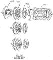
- the assembly can include a tread head, a two-piece pinion, a bearing disc, a bending element, a torsion bar, and the spindle.
- the two-piece spindle and bending element are mounted to the tread head, and the bearing disc is mounted to one side of the spindle.
- the torsion bar is mounted at one end to the tread head and at its opposite end to the spindle.
- a pretensioning device for use in seat belt retractor assembly includes a rotatable spindle configured for taking up seat belt webbing in response to rotation of the spindle, wherein the spindle rotates about a central longitudinal axis; a tread head pinion operative coupled to the spindle, the tread head pinion configured to rotate in response to a pretensioning load applied thereto, wherein rotation of the tread head rotates the spindle; and a deformable rod configured to translate along a predetermined path into direct engagement with the tread head pinion in response to actuation of the rod, wherein the translation and engagement of the rod with the tread head pinion rotates the tread head pinion.
- the tread head pinion may be formed as a single piece and includes: a first side facing away from the spindle and a second side facing toward the spindle; a ring portion extending between the first and second sides and having a plurality of radially protruding teeth for receiving the pretensioning load from the rod; a pair of flanges including a first flange at the first side and a second flange at the second side disposed on opposite sides of the teeth and projecting radially outward beyond the teeth, the flanges disposed longitudinally adjacent the plurality of teeth, wherein the teeth blend into the flanges to define a cavity between adjacent teeth and the flanges; and a bearing portion projecting axially from the second flange toward the spindle, the bearing portion defining a bearing surface against which the spindle will bear.
- a pretensioning device for use in seat belt retractor assembly includes a rotatable spindle configured for taking up seat belt webbing in response to rotation of the spindle, wherein the spindle rotates about a central longitudinal axis; a tread head pinion operative coupled to the spindle, the tread head pinion configured to rotate in response to a pretensioning load applied thereto, wherein rotation of the tread head rotates the spindle; and a deformable rod configured to translate along a predetermined path into direct engagement with the tread head pinion in response to actuation of the rod, wherein the translation and engagement of the rod with the tread head pinion rotates the tread head pinion
- the tread head pinion may be formed as a single piece and may include: a first side facing away from the spindle and a second side facing toward the spindle; a ring portion extending between the first and second sides and having a plurality of radially protruding teeth for receiving the pretensioning load from the rod; a pair of flanges including a first flange at the first side and a second flange at the second side disposed on opposite sides of the teeth and projecting radially outward beyond the teeth, the flanges disposed longitudinally adjacent the plurality of teeth, wherein the teeth blend into the flanges to define a cavity between adjacent teeth and the flanges.
- a torsion bar may extend into an inner cavity defined by the ring portion of the tread head pinion and may be attached to the tread head pinion at a first end and the spindle at a second end.
- FIG. 1 shows a vehicle seat 10 and a seatbelt assembly 12 in accordance with an exemplary embodiment.
- the seatbelt assembly 12 includes a seatbelt webbing 14 having a shoulder belt portion 16 extending from an upper guide loop or anchorage 18 to a latch plate 20 and a lap belt portion 22 extending from the latch plate 20 to an anchorage 24.
- the latch plate 20 can include a loop portion 26 through which the seatbelt webbing 14 extends.
- the latch plate 20 is able to be inserted into a seatbelt buckle 28 to lock and unlock the seatbelt assembly 12.
- vehicle structure e.g., vehicle frame
- the seatbelt webbing 14 is able to pay-out from a seatbelt pretensioning retractor assembly or retractor assembly 32 (shown in Figures 2 and 3 ), which is located within the vehicle seat 10 (in an integrated structural seat design) or is coupled structurally to the vehicle body, so that the effective length of the seatbelt webbing 14 is adjustable.
- a seatbelt pretensioning retractor assembly or retractor assembly 32 shown in Figures 2 and 3
- the seatbelt assembly 12 defines a three-point restraint between the anchorage 18, the latch plate 20, and the anchorage 24. Any other suitable configurations, such as alternative locations for the retractor assembly 32, the latch plate 20, and the anchorage 24, may be used with the present invention.
- FIG. 2 an isometric view of the seatbelt assembly 12 is illustrated disassociated from the motor vehicle and showing the retractor assembly 32 in accordance with an exemplary embodiment.
- the retractor assembly 32 includes a spool assembly 34 and a gas generator 36 mounted to a common frame 38.
- the spool assembly 34 is connected with and stows the seatbelt webbing 14 of the shoulder belt portion 16, whereas the end of the lap belt portion 22 of the seatbelt webbing 14 is fixedly engaged with the anchorage point, for example, the frame 38 or another portion of the motor vehicle such as the seat 10 (shown in Figure 1 ) or floor pan.
- the spool assembly 34 includes a belt spool or spindle 40 that engages the shoulder belt portion 16 of the seatbelt webbing 14 and rotates to wind-up or pay-out the seatbelt webbing 14.
- a torsional "clock” or “motor” type spring is carried within a spring end cap 42 and rotationally biases the belt spool 40 to retract the seatbelt webbing 14.
- the spool assembly 34 may further incorporate other spool control mechanisms that are known in accordance with the prior art, including pretensioners, inertia and webbing sensitive locking devices, torsion bar load limiters, or other belt control devices, some of which will be described in further detail below.
- Spool control systems may include any system that controls the rotational movement of a webbing spool, thus controlling the extraction and retraction of seatbelt webbing.
- One such spool control system is a motor-assisted retractor.
- Spool locking devices typically incorporate an inertia sensitive element, such as a rolling ball or pendulum, and cause a sprocket of the spool to be engaged to prevent further withdrawing of the seatbelt webbing 14 from the belt spool 40.
- Webbing sensitive locking devices sense rapid pay-out of seatbelt webbing 14 to lock the retractor assembly 32.
- Various electronic sensing mechanisms that detect the withdrawal of seatbelt webbing 14 and/or the connection of the latch plate 20 to the seatbelt buckle 28 may also be incorporated into the retractor assembly 32.
- the retractor assembly 32 allows pay-out of seatbelt webbing 14 to give the occupant a certain amount of freedom of movement. However, if an impact or a potential impact situation is detected, the retractor assembly 32 is locked to prevent pay-out and to secure the occupant in the seat 10. For example, if the vehicle decelerates at a predetermined rate or if the brakes are actuated with a predetermined force, then the retractor assembly 32 is locked. Due in part to the free pay-out of the seatbelt webbing 14, the seatbelt assembly 12 often develops slack during normal use.
- FIG 4 provides a cut-away illustration of a pretensioner system 44 in accordance with an exemplary embodiment.
- the retractor assembly 32 further incorporates the pretensioner system 44 operatively connected to the spool assembly 34 and operable to rotate the belt spool 40 for pretensioning.
- a retractor pretensioner winds seatbelt webbing into a more taught condition against the occupant at the initial stages of a detected vehicle impact. This is provided to reduce forward motion or excursion of the occupant in response to the deceleration forces of a vehicle impact or rollover.
- the pretensioner system 44 includes a pretensioner tube 52 in communication with the gas generator 36.
- the gas generator 36 is used to provide expanding gas in response to a firing signal.
- the vehicle includes a sensor array sending a signal indicative of an emergency event such as an impact event, crash, or rollover.
- the vehicle sensor may be a specific impact sensor, or may be a traditional vehicle sensor (e.g. a longitudinal or lateral acceleration sensor) or otherwise part of a control system having a suite of multiple sensors. Any other impact sensor that is or will be known to those skilled in the art may also be readily employed in conjunction with the seatbelt assembly 12 of present invention.
- An electronic control unit such as a central processing unit (CPU) or other controller receives a signal and controls the seatbelt assembly 12 to respond by tightening the seatbelt webbing 14 of the vehicle (e.g. via activation of a pretensioner).
- CPU central processing unit
- the pretensioner tube 52 has a pretensioner rod 53, e.g., a plastically deformable polymer rod, disposed therein that has an elongate shape and is flexible within the tube 52. More specifically and as will be discussed in further detail below, the pretensioner rod 53, when disposed outside of the pretensioner tube 52 prior to insertion therein, has a generally straight shape, and when inserted into the tube 52 it will bend and flex in accordance with the tortuous shape of the tube 52.
- a pretensioner rod 53 e.g., a plastically deformable polymer rod
- the common frame 38 includes a housing 54 for housing the components of the pretensioner system 44.
- the pretensioner system 44 includes a pretensioner assembly 60 that may include the spool or spindle 40, a torsion bar 62, a tread head pinion 64, and a bending element 66.
- the tread head pinion 64 may include numerous features previously contained in separate assembled parts.
- Figure 5A illustrates an exploded view, and the tread head pinion 64 is arranged to attach directly to the torsion bar 62 (which is inserted into the tread head pinion 64), and the torsion bar 62 is also arranged to attach directly to the spindle 40 (inside the spindle; not shown).
- the bending element 66 which may be a digressive bending element, attaches to both the tread head pinion 64 and the spindle 40.
- the bending element 66 may attach to the spindle 40 via a bending element insert 67.
- the spindle 40 bears against the tread head pinion 64, allowing the spindle 40 to rotate relative to the tread head pinion 64 if necessary during the pretensioning.
- Figure 5B illustrates the bending element 66 attached to the tread head pinion 64.
- the torsion bar 62 and bending element 66 operate in a manner known in the art, which allows for the load imparted on the passenger during pretensioning to be tailored.
- the torsion bar 62 may twist in response to a load on the seatbelt and spindle exceeding a predetermined level, thereby allowing some payout of the seatbelt webbing by allowing the torsion bar 62 and spindle to twist relative to the pretensioned and locked tread head pinion 64.
- the payout that occurs reduces the load on the passenger relative to a fully locked belt.
- the tread head pinion 64 is formed as a single piece.
- the pinion 64 may be formed by sintering or die-casting and made from zinc or aluminum.
- the tread head pinion 64 may be described herein with reference to various portions or features of the one-piece design. It will be appreciated that references to various portions or features are intended to refer to a portion or feature of the single piece design of the tread head pinion 64.
- the tread head pinion 64 has a generally circular profile, such that the tread head pinion 64 may rotate generally along with the spindle (although some relative rotation between the tread head pinion 64 and the spindle is possible depending on deformation of the torsion bar 62 during periods of high loading).
- the tread head pinion 64 may also be described as having a disc-like shape, with a first side 70 facing a first direction and a second side 72 facing a second direction that is opposite the first direction.
- the pinion 64 may also include a body portion 74 extending axially between the first and second sides.
- the tread head pinion 64 has a central axis A about which the tread head pinion 64 will rotate with the spindle.
- the first side 70 is disposed axially farther away from the spindle 40 than the second side 72. Put another way, the first side 70 faces away from the spindle 40, with the second side 72 facing the spindle 40.
- the second side 72 is arranged to engage the spindle 40 when assembled.
- the first side 70 may include various structure corresponding to the traditional function of a seatbelt spool assembly, such as the structure that cooperates with the inertia lock.
- the first side 70 may include a shaft portion 76 that projects axially outward from the first side 70.
- the shaft portion 76 is arranged to cooperate with the frame or assembly housing or other structure to allow the tread head pinion 64 to rotate during web payout or pay in under normal operating conditions, and allows the tread head pinion 64 to rotate in response to pretensioning to take up seat belt webbing.
- the body 74 of the tread head pinion 64 is arranged to receive the driving element of the pretensioning assembly.
- the driving element may be in the form of the polymer rod 53 that is driven through the tube 52 and into engagement with a radially outer portion of the tread head pinion 64. With the polymer rod 53 engaging with a radially outer portion of the pinion 64, the pinion 64 will be rotated in response to the driving force of the polymer rod 53.
- the use of the polymer rod 53 as the driving element is described herein, but it will be appreciated that aspects of the one-piece tread head 64 may also be used with other types of driving elements.
- the body 74 includes a driving element receiving ring portion 78 extending circumferentially around the radially outer edge of the body 74 and defining the radially outer surfaces of the tread head pinion 64.
- the ring portion 78 includes a first flange 78a and a second flange 78b.
- the first flange 78a is disposed adjacent the first side 70
- the second flange 78b is disposed adjacent the second side 72.
- the flanges 78a and 78b extend radially outward from the central axis A and define an inner space 78c axially between the first flange 78a and the second flange 78b.
- the space 78c between the flanges 78a 78b is designed to receive the polymer rod 53 or other driving element that is driven into engagement with the tread head pinion 64 during pretensioning.
- the flanges 78a and 78b therefore have an inner surface and an outer surface, with the inner surfaces facing the inner space 78c, and the outer surfaces facing axially outward.
- the flanges 78a and 78b may include a chamfered inner edge 78d at the radially outer inner corner of the flanges 78a and 78b.
- This chamfered edge 78d may operate to guide the driving element or polymer rod 53 into the inner space 78c during pretensioning.
- the chamfered edge 78d preferably extends circumferentially around the entire perimeter of the flanges 78a and 78b.
- One or both of the flanges 78a and 78b may include radially outer notches 78e extending into the flanges 78a and 78b.
- the ring 78 further includes a plurality of teeth 80 that extend between the flanges 78a and 78b in the inner space 78c.
- the teeth 80 are designed to engage with the driving element 53, such that when the driving element 53 is driven during pretensioning, the driving element will impact on the teeth 80, causing the tread head pinion 64 and attached spindle 40 to rotate.
- the teeth 80 are preferably evenly spaced circumferentially around the ring 78.
- the teeth 80 when viewing a cross-section of the teeth 80 in the axial direction, each have a radially outer apex 80a, a first face 80b, and a second face 80c.
- the first face 80b and second face 80c may be arranged at different angles relative to the apex and the central axis A.
- the first face 80b is arranged at an angle ⁇ from the reference line
- the second face 80c is arranged at an angle ⁇ from the reference line, such that ⁇ is less than or equal to ⁇ .
- the angle ⁇ is less than the angle ⁇ .
- the angle ⁇ can be approximately 25 degrees and the angle ⁇ can be approximately 30 degrees.
- the first face 80b is preferably disposed at the side of the tooth 80 that faces the driving element 53, such that when the driving element 53 is driven into engagement with the teeth 80, the driving element will impact on the first face 80b.
- the reduced angle of the first face 80b increases the ratio of pinion tangential force to radial force when the driving element 53 begins pushing on the tread head pinion 64.
- the ring 78 may also include a base surface 82 that is disposed radially inward from the apex 80a of the teeth 80.
- the base surface 82 may define the base of each of the teeth 80.
- the intersections between the teeth 80, the flanges 78a and 78b, and the base surface 82 may be in the form of fillets 82a, thereby defining a plurality of curved pockets 84 within the inner space 78c.
- the fillets 82a thereby take up part of the inner space 78c, which reduces the ability of the polymer rod to deform into the space near the intersections of the teeth 80, flange 78a/b, and base surface 82. Excessive rod deformation wastes energy, so the reduction in space into which the rod 53 can deform reduces the amount of potential wasted energy.
- the second side 72 of the tread head pinion 64 includes the structure that attaches to the torsion bar 62 and the bending element 66, as well as providing the bearing surface for the spindle 40.
- the second side 72 includes a spindle bearing portion 84 that extends axially outward away from the second flange 78b.
- the bearing portion 84 has a generally circular profile and forms a stepped surface extending from the body 74 and the second flange 78b.
- the bearing portion 84 has an outer diameter that is smaller than the outer diameter of the second flange 78b, such that the second flange 78b extends radially outward relative to the bearing portion 84.
- a bending element mounting portion 86 extends axially outward from the bearing portion 84.
- the bending element mounting portion 86 has a generally circular profile with an outer diameter that is smaller than the outer diameter of the bearing portion 84, such that the bearing portion 84 extends radially outward from the bending element mounting portion 86.
- the bending element mounting portion 86, the bearing portion 84, and the body 74 of the one-piece tread head pinion 64 combine to define an inner cavity 88 extending axially inward into the tread head pinion 64 from the axial outer surface of the bearing element mounting portion 86.
- the cavity 88 is centered on the axis A, and has a splined profile when viewed axially.
- the splined shape of the cavity 88 corresponds to an end shape of the torsion bar 62, such that the torsion bar 62 may be inserted axially into the cavity 88 and fixed rotationally relative to the tread head pinion 64.
- the splined profiles of the cavity 88 and the torsion bar 62 operate to transfer torque between the tread head pinion 64 and the torsion bar 62.
- the bending element mounting portion 86 includes a notch 86a that extends radially inward from an outer circumferential surface of the bending element mounting portion 86.
- the notch 86a provides a pocket or a space in which an end portion of the bending element 66 may be disposed.
- the bearing portion 84 similarly includes a staking pocket 84a disposed axially adjacent the notch 86a, such that the open space of the notch 86a communicates with the pocket 84a.
- the pocket 84a extends axially inward into the bearing portion 84.
- the bearing portion 84 also includes an access cavity 84b extending axially inward into the bearing element at a location disposed radially adjacent and outward from the staking pocket 84a.
- a staking wall 84c is defined between the pocket 84a and the cavity 84b. The staking wall 84c is deformable in a radial direction to stake the end of the bending element 66 (which is inserted into the pocket 84a) to the tread head pinion 64.
- the bending element mounting portion 86 has a continuously smooth outer circumferential surface over a majority of the circumference.
- the outer circumferential surface therefore has a generally constant diameter around the majority of the circumference, except for the area where the notch 86a is located.
- prior tread head designs required a splined outer surface of the tread head 464 where the bending element 66 would wrap around it. This was due to the tread head 464 and pinion 478 being separate pieces.
- the pinon 478 included a splined inner opening that cooperated with the splined outer surface of the tread head 464, such that the pinion 478 could be assembled with the tread head 464 and that torque from the pinion 478 would be transferred to the tread head 464.
- the splined portion of the tread head 464 extended through the pinion 478 and projected outward, with the portion projecting beyond the pinion 478 being the portion that the bending element 66 wrapped around. This portion of the tread head 464 is required to be splined because the splined pinion 478 needed to pass over it during assembly.
- the bending element 66 is provided with a smooth circumferential bearing surface 86b around the bending element mounting portion 86 rather than a splined bearing surface.
- the bearing portion 84 extends axially outward from the flange 78b.
- the bearing portion 84 provides a bearing surface 84d against which the spindle 40 can bear as the spindle 40 rotates relative to the pinion 64.
- the spindle 40 does not rotate relative to the tread head 64.
- the torsion bar 62 twists in response to a load on the seatbelt webbing, the spindle 40 rotates relative to the tread head 64, and will bear against the bearing portion 84.
- the bearing surface 84d has a generally annular shape that surrounds the bending element mounting portion 86.
- the above described cavity 84a for staking the bending element 66 extends axially into the bearing surface 84d.
- the bearing portion 84 may further include a plurality of core outs 84e.
- the core outs 84e are in the form of cavities or other holes formed in the bearing surface 84d. The core outs 84e reduce the overall weight of the tread head 64, and the one-piece form of the tread head 64 allows the bearing surface 84d to remain robust.
- a separate bearing disc 484 was placed against the pinion 478 between the pinion 478 and the spindle 40.
- the bearing disc 484 would include an internal opening with a splined inner profile such that the bearing disc 484 would fit over the splined tread head 464, similar to the pinion 478.
- the bearing disc 484 also included a notch in the inner profile to hold the bending element 66 in place. The bending element 66 would be engaged with the bearing disc 484, and then the bearing disc 484 and bending element 66 would be placed over the splined portion of the tread head 464.
- the above described approach does not include a separate bearing disc, and the bending element 66 may simply be inserted into the notch 86a and cavity 84a and staked by deforming the wall 84c.
- an alternative tread head 564 may be arranged to receive a separate bearing disc 584.
- the one-piece construction may include the body 74 and an alternative version of a bending element mounting portion 586.
- the bearing disc 584 is sized and arranged to be disposed over the bending element mounting portion 586.
- the bending element mounting portion 586 includes an axially inner portion 586a and an axially outer portion 586b relative to the body 74.
- the inner portion 586a has an outer profile configured to engage with an inner profile of the bearing disc 584.
- the outer portion 586b is configured to engage with the bending element 66 as it bends.
- the bending element portion 586 includes protrusions 587a, b, c. d, e, and f disposed around the outer profile of the bearing element portion 586.
- Protrusion 587a has an inner portion 587g and an outer portion 587h, where the inner portion 587g has a trapezoidal shape and the outer portion 587h has a pointed shape.
- the inner portion 587g engages the bearing disc 584, and the outer portion 587h engages the bending element 66.
- the protrusion 587b has an elongated box shape with a radially outer flat surface.
- the protrusions 587c, d, e, and f have box or trapezoidal shapes. It will be appreciated that other shapes of the protrusions 587 could also be used.
- the bending element mounting portion 586 may also include radial depressions in the outer surface. Depression 588a is disposed circumferentially adjacent protrusion 587a, and depression 588b is disposed circumferentially adjacent protrusion 586f. Depression 588c is disposed circumferentially adjacent protrusion 586e.
- the bearing disc 584 has recesses 584a that correspond to the protrusions 586a, b, c, d, e, and f of the bending element mounting portion 586, and a recess 584b for receiving the bending element 66.
- the recesses are defined by projections 585 that extend radially inward from the inner profile of the bearing disc 584.
- the bearing disc 584 defines a flat surface 584c that corresponds to protrusion 586b.
- the bearing disc 584 may include a nub 584d disposed on one of the projections 585, and another nub 584e disposed on another of the projections 585.
- the nub 584d corresponds to the depression 588c and the nub 584e corresponds to the depression 588b.
- the bending element 66 may be disposed on the bending element mounting portion 586, with the bearing disc 584 covering a portion of the bending element 66 at the recess 584b to hold the bending element 66 between the bending element mounting portion 586 and the bearing disc 584.
- the bearing disc 584 provides the bearing surface described above, and the bending element 66 will wrap around the bending element mounting portion 586 similar to manner described above.
- the one-piece form of the tread head 64 or the tread head 564 (relative to a multi piece assembly of Figure 9A that assembles the tread head 464, pinion 478, and bearing disc 484), allows the depth of the space 78c between the pinion teeth 80 to be greater, or provides additional structural stability relative to the separate pinion 478.
- the depth between the pinion teeth was limited because the pinion 478 had to pass over the splined projection of the tread head 464.
- the base of the space between the pinion teeth would always be radially outside of the outermost surface of the splined projection of the tread head 464, because the separate pinion 478 passed over the splined projection.
- the outermost surface of the tread head 464 projection beyond the bearing disc 484 also acted as the surface around which the bending element 66 would wrap.
- the depth of the space 78c between the teeth 80 can extend into the body of the tread head 64 or tread head 564 radially inward of the outermost surface of the bending element mounting portion 86. This is not possible in the prior multi-piece design.
- the use of a one-piece design relative to a multi-piece design also provides manufacturing advantages.
- the tread head 64 or 564 may be die-cast, sintered, or injection molded.
- the use of a one-piece design also reduces the overall tolerance band in the axial direction relative to the multi-piece design.
- the one-piece tread head pinion 64 or 564 therefore combines with the spindle 40 as part of the spool assembly 34.
- the spool assembly 34 cooperates with the other components of the retractor assembly 32, which includes the components for pretensioning, as well as the components for normal operation of the retractor.
- the spool assembly 34 includes the tread head pinion 64/564 that is disposed within the housing 54.
- the pinon 64/564 is attached to the belt spool 40. Rotation of the pinion 64/564 will cause the attached belt spool 40 to rotate to wind the seatbelt webbing 14 that is attached to the belt spool 40.
- Figure 10A provides a side cut-away illustration of the pretensioner rod 53 and a stopper 55 in accordance with an exemplary embodiment.
- the pretensioner rod 53 has a generally circular cross-section in one form.
- the pretensioner rod 53 could have a non-circular cross-section, such as a generally rectangular cross-section, generally triangular cross-section, or other polygonal cross-section that allows the pretensioner rod 53 to be inserted into the pretensioner tube 52 (shown in Figure 4 ) and adapt to the tortuous shape of the pretensioner tube 52 when inserted.
- the pretensioner rod 53 will be discussed as having a generally circular cross-section.
- the pretensioner rod 53 when disposed outside of the pretensioner tube 52, has a generally straight shape and extends in a longitudinal direction 200 from a proximal end portion 202 to a distal end portion 204.
- the proximal end portion 202 is disposed towards the gas generator 36 (shown in Figure 10C ) when the pretensioner rod 53 is installed within the pretensioner system 44.
- the pretensioner rod 53 has a cross-section that varies along its length to define a non-recessed portion 206 and a recessed portion 208 that defines a recess 210.
- the recess 210 is configured as a groove, e.g., U-shaped groove with sidewalls.
- the recessed portion 208 extends along a majority of the overall length of the pretensioner rod 53 from the proximal end portion 202 to and including the distal end portion 204.
- the proximal end portion 202 includes the non-recessed portion 206 in which the recess 210 terminates at a distal-most section of the non-recessed portion 206.
- the non-recessed portion 206 of the pretensioner rod 53 has a diameter, cross-sectional dimension, and/or perimeter greater than the recessed portion 208.
- the non-recessed portion 206 has a length L1 of from about 15 to about 25 mm, such as about 20 mm and a width W1 of from about 4 to about 7 mm, and the recessed portion 208 has a length L2 of from about 60 to about 145 mm and a thickness W2 of from about 2.5 to about 8.0 mm.
- the pretensioner rod 53 also includes a positive feature 216, e.g., nub or post, extending proximally from the proximal end portion 202.
- the stopper 55 has a negative feature 218 formed therein that receives the positive feature 216 to couple the stopper 55 to the proximal end portion 202 of the pretensioner rod 53.
- the negative feature 218 and the positive feature 216 are sized such that the stopper 55 is compression fit, e.g., interference fit, onto the positive feature 216 to fixedly couple the stopper 55 to the pretensioner rod 53.
- the positive feature 218 can be configured as a blind hole 220.
- the negative feature 220 can be configured as a through-hole 222 with the positive feature 216 extending partially or fully therethrough.
- the pretensioner rod 53 is made from a polymer material, which has a reduced weight relative to metallic ball driving elements of other roto-pretensioners.
- the particular polymer material can be selected to fit the particular desires of the user.
- the polymer material is preferably one that has sufficient flexibility such that it can bend and flex through the pretensioner tube 52 to allow for initial installation as well as in response to actuation by the gas generator 36.
- the polymer material is preferably one that has sufficient pushability in response to actuation, such that the pretensioner rod 53 will sufficiently transfer a load to a tread head pinion 64 of the pretensioner system 44, thereby functioning as a driving element for causing pretensioning.
- the pretensioner rod 53 is made from a polymer material that is plastically deformable. During and after actuation, the pretensioner rod 53 will be become plastically deformed in response to actuation and contact with other components (e.g., the tread head pinion 64) of the pretensioner system 44. As will be discussed in further detail below, this plastic deformation will cause the pretensioner rod 53 to become locked, for example, in the tread head pinion 64 to prevent or limit payback of the pretensioner rod 53 without being completely dependent on maintained pressure in the system.
- the pretensioner rod 53 is made from a nylon thermoplastic material.
- the pretensioner rod 53 could also be made from a aliphatic polyamide thermoplastic material.
- the pretensioner rod 53 could be made from a similar thermoplastic material, such as an acetal material or polypropylene material.
- the housing 54 further include a guide portion 90.
- the guide portion 90 is disposed within the housing 54 similar to the tread head pinion 64. More particularly, the guide portion 90 is disposed opposite the exit of the tube 52, and the tread head pinion 64 is disposed between the guide portion 90 and the tube 52. Accordingly, the pretensioner rod 53 exiting the tube 52 will contact the tread head pinion 64 prior to contacting the guide portion 90.
- the guide 90 has a generally arcuate landing surface 92 that has a concave shape toward the exit of the tube 52.
- the arc of the surface 92 has a constant radius.
- the center point of the radius of the arc is aligned with the rotational axis of the tread head pinion 64, such that the radial spacing between the surface 92 and the tread head pinion 64 is consistent along the length of the surface 92.
- the center point of the radius of the surface 92 could be offset from sprocket axis, such that the radial spacing between the surface 92 and the outer diameter of the tread head pinion 64 will vary at different points along the surface 92.
- the surface 92 includes a first end 96 and second end 98.
- the first end 96 is disposed opposite the exit of the tube 52 such that the pretensioner rod 53 would engage the first end 96 prior to the second end 98 after exiting the tube 52 and passing the tread head pinion 64.
- the housing 54 further defines an overflow cavity 100 that is disposed opposite the guide 90.
- the overflow cavity 100 is also disposed adjacent the curvature of the tube 52, and the tread head pinion 64 is disposed between the guide 90 and the overflow cavity 100. Accordingly, an intermediate portion 101 of the guide 90 is diametrically opposite the overflow cavity 100 across the tread head pinion 64.
- the overflow cavity 100 is sized and configured to allow a portion the pretensioner rod 53 to be received therein during actuation of pretensioner system 44, if necessary. For example, after the pretensioner rod 53 has exited the tube 52 it will contact the guide 90 and be directed in an arcuate path corresponding to the guide 90, such that the pretensioner rod 53 is ultimately directed toward the overflow cavity 100.
- the pretensioner rod 53 can extend into the overflow cavity 100, and can further be guided along the curvature of the tube 52 that is adjacent the overflow cavity 100. However, it will be appreciated that the pretensioner rod 53 may not necessarily travel far enough during actuation to ultimately reach the overflow cavity 100.
- the retractor assembly 32 includes the gas generator 36 that provides expanding gas in response to a firing signal.
- the expanding gas causes an increase in pressure within the tube 52, which ultimately causes the pretensioner rod 53 to be forced away from the gas generator 36, through the tube 52, and pass the exit into the tread head pinion 64 for pretensioning.
- the pretensioner tube 52 includes a piston or seal member 102.
- the seal member 102 can have a spherical shape with a spherical outer surface, in one approach. In another approach, the seal member 102 can have a generally cylindrical shape with a cylindrical outer surface.
- the seal member 102 is slidably disposed within the tube 52 and is operable to drive the pretensioner rod 53 along an actuating direction or path A. As will be understood by those of skill in the art, the seal member 102 may be press-fitted or otherwise fitted inside the tube 52.
- the seal member 102 defines a proximal end 106 spaced from the gas generator 36 so as to define a gas chamber 108 therebetween.
- the seal member 102 defines a distal end 110 directed toward the stopper 55 and the pretensioner rod 53.
- the stopper 55 is preferably made from aluminum, but could be made from another suitable material of sufficient strength, such as steel, other metal or metal alloy, or reinforced plastic with the seal member 102 being generally softer such that it can provide the described sealing abilities.
- the stopper 55 has an outer perimeter that substantially matches the perimeter of the non-recessed portion 206. The stopper 55 is adjacent the distal end 110 of the seal member 102 and abuts the non-recessed portion 206 of the pretensioner rod 53.
- the seal member 102 and the stopper 55 cooperate to transfer the energy from the increased pressure in the gas chamber 108 to the pretensioner rod 53.
- the pretensioner rod 53 in order to travel through the tube 52 and flex according to the curvature of the tube 52, is sized slightly smaller than the width of the tube 52. Thus, without the seal member 102, gas from the gas generator 36 would flow past the pretensioner rod 53 in the space defined between the pretensioner rod 53 and the tube 52.
- the seal member 102 defines a generally elastic structure, and may be composed of various materials known in the art, such as any suitable plastic or polymer (e.g., polyester, rubber, thermoplastic, or other elastic or deformable material). Moreover, the seal member 102 may be die cast, forged, or molded from metal, plastic, or other suitable material. In one embodiment, the seal member 102 is formed using a two-cavity injection molding process.
- the generally elastic structure allows the shape of the seal member 102 to change slightly in response to pressure, thereby improving the sealing that it provides.
- the gas generator 36 produces expanding gas that pressurizes the gas chamber 108, thereby enabling the seal member 102 to forcibly drive the pretensioner rod 53 along the actuation path A.
- the pretensioner rod 53 As the pretensioner rod 53 is driven through the tube 52, it engages the tread head pinion 64. More particularly, the pretensioner rod 53 engages the teeth 80 of the tread head pinion 64. Engagement of the pretensioner rod 53 with the tread head pinion 64 as the pretensioner rod 53 is driven by expanding gas in the direction of arrow A causes the belt spool 40 (shown in Figure 3 ) to rotate, which in turn provides pretensioning.
- the seal member 102 is composed of a relatively elastic material. Therefore, pressurized gas within the gas chamber 108 causes the proximal end 106 of the seal member 102 to expand, which helps prevent gas from escaping past the seal member 102.
- the seal member 102 of the present invention is operable to retain a high seal pressure as well as maintain residual gas pressure within the tube 52.
- pretensioning of the seatbelt there can be a side-effect known as payback, where the tension on the seatbelt caused by the occupant during an event triggering pretensioning can rotate the spool in a direction opposite the pretensioning rotation. This rotation is transferred to the tread head pinion 64 and the driving elements, causing the driving elements to travel in the reverse direction within the tube 52. Payback can be counteracted by maintaining pressure in the tube 52, but this requires the gas generator 36 to fire for a longer period and additional propellant.
- the pretensioner system 44 described herein includes features configured to counteract the above described payback side-effect as an alternative to or in addition to maintained gas pressure.
- the pretensioner rod 53 is preferably made of a plastically deformable material, such as a polymer.
- the pretensioner rod 53 exits the tube 52 and contacts the teeth 80 of the tread head pinion 64, causing the tread head pinion 64 to rotate.
- additional ones of teeth 80 will contact the side of the pretensioner rod 53, causing the pretensioner rod 53 to be compressed and deformed plastically in the area of interference between the teeth 80 and the pretensioner rod 53.
- This compression will also cause the pretensioner rod 53 to be compressed against the guide 90, creating a press-fit configuration of the pretensioner rod 53 between the tread head pinion 64 and the guide 90.
- the pretensioner rod 53 and guide 90 may be made from materials that will weld together at the end of the pretensioning stroke.
- the materials of the pretensioner rod 53 and guide 90 may be selected such that heat generated from the friction between the pretensioner rod 53 and the guide 90 will cause the pretensioner rod 53 and guide 90 to become welded together along an interface W where the guide 90 and rod 53 contact each other.
- the pretensioner rod 53 and guide 90 Once the pretensioner rod 53 and guide 90 are welded together, the pretensioner rod 53 will become locked and prevented or substantially limited from traveling back into the tube 52.
- the plastic deformation of the pretensioner rod 53 caused by the teeth 80 will prevent or substantially limit the tread head pinion 64 from rotating in the opposite direction, thereby preventing or substantially limiting payback.
- the materials used for each are preferably in the same family.
- the pretensioner rod 53 is preferably nylon.
- the guide 90 is acetal, then the pretensioner rod 53 is preferably acetal.
- the guide 90 is polypropylene, then the pretensioner rod 53 is polypropylene. It will be appreciated that other materials that will weld together under high heat and pressure could also be used. Moreover, it will be appreciated that some different types of materials can weld together.
- a low-resistance condition Another side-effect that can occur during pretensioning is known as a low-resistance condition. This can occur when there is a relatively large portion of the seatbelt webbing that can be taken up or wound by the spool in response to actuating the pretensioner. For example, if there was extra slack in the seatbelt, this slack would be taken up and wound with lower resistance because it would not be acting on the occupant until the slack was taken up. In a low resistance condition, the backpressure of the driving elements is reduced. Reduced backpressure can result in a reduced ability of the sealing element to expand circumferentially against the inner wall surface of the tube in response to the backpressure. This can occur for any type of piston or seal that is configured to expand circumferentially in response to backpressure as part of its sealing process.
- the tube 52 includes a projection 120 extending within the tube 52 near an end of the tube 52 to form a constriction portion 130 proximate to where the pretensioner rod 53 exits, thereby reducing the cross-sectional area of the tube 52 in a distinct location. That is, the opening diameter, width, or dimension(s) of the constriction portion 130 is smaller than the diameter, width, or dimension(s) of adjacent portions of the tube 52 portions, such as, for example, the portions of the tube 52 that are upstream from the constriction portion 130.
- the recess 210 is aligned with the projection 120 along the actuating direction or path A such that during actuation and/or pretensioning, the recessed portion 208 of the pretensioner rod 53 is not obstructed by the projection 120.
- the constriction portion 130 is sized such that there is enough space that at least the recessed portion 208 of the pretensioner rod 53 can travel past the constriction portion 130, but the stopper 55 and seal member 102 will be blocked from travelling past the constriction portion 130. When the stopper 55 and the seal member 102 are blocked from advancing past the constriction portion 130, the constriction portion 130 provides additional backpressure.
- the seal member 102 will circumferentially or radially expand in response to this backpressure, thereby providing an improved seal in low-resistance conditions.
- This improved sealing will prevent or limit the potential for gas to escape from the tube in low-resistance conditions.
- the projection 120 defining the constriction portion 130 can be formed in a variety of ways and have a variety of shapes while providing the above described functionality.
- the projection 120 with the recess 210 of the pretensioner rod 53 aligned therewith may be disposed along an inboard portion of the tube 52 as illustrated in Figures 4 and 11 , or alternatively, may be disposed along an outboard portion of the tube 52, as illustrated in Figures 8 and 12 .
- disposition of the projection 120 on the inboard portion of the tube 52 facilitates the pretensioner rod 53 sliding across the outboard portion of the tube 52 during travel.
- the centrifugal force of the pretensioner rod 53 as it travels through the tube 52 will tend to force the pretensioner rod 53 toward the outboard portion of the tube 52, so locating the projection 120 on the inboard portion helps reduces the potential for the constriction portion 130 to add resistance to the pretensioner rod 53.
- disposition of the projection 120 on the outboard portion of the tube 52 facilitates the tread head pinion 64 engaging the fully or solid side of the pretensioner rod 53 (e.g., tread head pinion 64 engaging side of the pretensioner rod 53 opposite the recess 210) during actuation to facilitate locking the pretensioner rod 53 with the tread head pinion 64 to prevent or reduce any translation of the pretensioner rod 53 in a direction opposite the actuating direction or path A.
- the pretensioner rod 53 has the non-recessed portion 206 at its proximal end portion 202, where the non-recessed portion 206 has a larger diameter or cross-sectional dimension(s) than the recessed portion 208.
- the non-recessed portion 206 has a diameter or cross-sectional dimension(s) that is larger than the width or cross-sectional dimension(s) of the tube 52 at the constriction portion 130. Accordingly, with the non-recessed portion 206 disposed upstream of the constriction portion 130, the constriction portion 130 will prevent the non-recessed portion 206 from passing.
- the non-recessed portion 206 can be smaller than the width or cross-sectional dimension(s) of the tube 52 at the constriction portion 130. With the non-recessed portion 206 being small enough to pass the constriction potion 130, it can pass beyond the constriction portion 130.
Landscapes
- Engineering & Computer Science (AREA)
- Mechanical Engineering (AREA)
- Automotive Seat Belt Assembly (AREA)
Applications Claiming Priority (1)
| Application Number | Priority Date | Filing Date | Title |
|---|---|---|---|
| US15/881,325 US10723310B2 (en) | 2018-01-26 | 2018-01-26 | Seatbelt pretensioning retractor assembly |
Publications (2)
| Publication Number | Publication Date |
|---|---|
| EP3517373A1 true EP3517373A1 (fr) | 2019-07-31 |
| EP3517373B1 EP3517373B1 (fr) | 2020-12-16 |
Family
ID=65033500
Family Applications (1)
| Application Number | Title | Priority Date | Filing Date |
|---|---|---|---|
| EP19152079.0A Active EP3517373B1 (fr) | 2018-01-26 | 2019-01-16 | Ensemble rétracteur de précontrainte de ceinture de sécurité |
Country Status (5)
| Country | Link |
|---|---|
| US (1) | US10723310B2 (fr) |
| EP (1) | EP3517373B1 (fr) |
| JP (1) | JP6731082B2 (fr) |
| KR (1) | KR102615602B1 (fr) |
| CN (1) | CN110077358B (fr) |
Families Citing this family (7)
| Publication number | Priority date | Publication date | Assignee | Title |
|---|---|---|---|---|
| JP6620069B2 (ja) * | 2016-06-09 | 2019-12-11 | 株式会社東海理化電機製作所 | ウェビング巻取装置 |
| DE102017221028B4 (de) * | 2017-11-24 | 2021-02-11 | Autoliv Development Ab | Gurtstraffer mit einem massekörperantrieb |
| WO2019191779A1 (fr) * | 2018-03-30 | 2019-10-03 | Joyson Safety Systems Acquisition Llc | Rétracteur de ceinture de sécurité |
| WO2021006128A1 (fr) | 2019-07-08 | 2021-01-14 | 住友金属鉱山株式会社 | Matériau actif d'électrode positive pour batteries secondaires au lithium-ion et batterie secondaire au lithium-ion |
| DE102019211852B3 (de) | 2019-08-07 | 2020-12-10 | Autoliv Development Ab | Gurtaufroller |
| JP7324651B2 (ja) | 2019-08-09 | 2023-08-10 | Joyson Safety Systems Japan合同会社 | プリテンショナ、リトラクタ及びシートベルト装置 |
| CN115027408B (zh) * | 2022-06-10 | 2023-05-05 | 重庆交通职业学院 | 一种安全带卷收器用锁止机构 |
Citations (6)
| Publication number | Priority date | Publication date | Assignee | Title |
|---|---|---|---|---|
| US5881962A (en) | 1994-04-11 | 1999-03-16 | Autoliv Development Ab | Mass-body drive for a rotary tightening device |
| US20060243843A1 (en) | 2005-04-27 | 2006-11-02 | Autoliv Asp, Inc. | Pretensioner device for a seatbelt retractor |
| US20100044489A1 (en) * | 2008-08-21 | 2010-02-25 | Jorge Lombarte | Device for pretensioning a seatbelt |
| US20120006925A1 (en) | 2010-07-06 | 2012-01-12 | Jon Burrow | High Seal Retractor Pretensioner Piston |
| US20150224960A1 (en) * | 2012-09-27 | 2015-08-13 | Trw Automotive Gmbh | Belt retractor for a seat-belt |
| EP3254909A1 (fr) * | 2016-06-06 | 2017-12-13 | TRW Automotive GmbH | Enrouleur de ceinture pour un système de ceinture de sécurité de véhicule |
Family Cites Families (12)
| Publication number | Priority date | Publication date | Assignee | Title |
|---|---|---|---|---|
| JPS5246635B2 (fr) * | 1974-04-23 | 1977-11-26 | ||
| JP3048111B2 (ja) * | 1994-06-28 | 2000-06-05 | 東邦レーヨン株式会社 | ステアリングホイールおよびその製造方法 |
| JP4475080B2 (ja) * | 2004-09-29 | 2010-06-09 | マツダ株式会社 | 車両の樹脂製フェンダー構造 |
| US7318607B2 (en) | 2004-10-19 | 2008-01-15 | Autoliv Asp, Inc. | Adaptive restraint system with retractor pretensioner |
| US7963473B2 (en) | 2004-10-19 | 2011-06-21 | Autoliv Asp, Inc. | Retractor with pretensioner |
| US7581757B2 (en) | 2004-10-19 | 2009-09-01 | Autoliv Asp, Inc. | Retractor with pretensioner |
| JP5246635B2 (ja) * | 2007-05-01 | 2013-07-24 | オートリブ ディベロップメント エービー | ウェビング巻取り装置 |
| DE102008008041B4 (de) * | 2008-02-05 | 2012-03-22 | Takata-Petri Ag | Gurtaufroller mit Strafferantrieb |
| KR101284239B1 (ko) * | 2011-02-21 | 2013-07-09 | 주식회사 디비아이 | 로드 리미터 |
| JP6389394B2 (ja) * | 2014-08-07 | 2018-09-12 | Joyson Safety Systems Japan株式会社 | プリテンショナ、リトラクタ及びシートベルト装置 |
| KR101766841B1 (ko) * | 2015-07-27 | 2017-08-09 | 아우토리브 디벨롭먼트 아베 | 프리텐셔너 장치 |
| JP6620069B2 (ja) * | 2016-06-09 | 2019-12-11 | 株式会社東海理化電機製作所 | ウェビング巻取装置 |
-
2018
- 2018-01-26 US US15/881,325 patent/US10723310B2/en active Active
-
2019
- 2019-01-03 CN CN201910004267.0A patent/CN110077358B/zh active Active
- 2019-01-04 KR KR1020190001366A patent/KR102615602B1/ko active IP Right Grant
- 2019-01-05 JP JP2019000366A patent/JP6731082B2/ja active Active
- 2019-01-16 EP EP19152079.0A patent/EP3517373B1/fr active Active
Patent Citations (7)
| Publication number | Priority date | Publication date | Assignee | Title |
|---|---|---|---|---|
| US5881962A (en) | 1994-04-11 | 1999-03-16 | Autoliv Development Ab | Mass-body drive for a rotary tightening device |
| US20060243843A1 (en) | 2005-04-27 | 2006-11-02 | Autoliv Asp, Inc. | Pretensioner device for a seatbelt retractor |
| US20100044489A1 (en) * | 2008-08-21 | 2010-02-25 | Jorge Lombarte | Device for pretensioning a seatbelt |
| US7988084B2 (en) | 2008-08-21 | 2011-08-02 | Autoliv Asp, Inc. | Device for pretensioning a seatbelt |
| US20120006925A1 (en) | 2010-07-06 | 2012-01-12 | Jon Burrow | High Seal Retractor Pretensioner Piston |
| US20150224960A1 (en) * | 2012-09-27 | 2015-08-13 | Trw Automotive Gmbh | Belt retractor for a seat-belt |
| EP3254909A1 (fr) * | 2016-06-06 | 2017-12-13 | TRW Automotive GmbH | Enrouleur de ceinture pour un système de ceinture de sécurité de véhicule |
Also Published As
| Publication number | Publication date |
|---|---|
| CN110077358B (zh) | 2022-08-09 |
| KR102615602B1 (ko) | 2023-12-19 |
| EP3517373B1 (fr) | 2020-12-16 |
| JP6731082B2 (ja) | 2020-07-29 |
| US20190232916A1 (en) | 2019-08-01 |
| CN110077358A (zh) | 2019-08-02 |
| US10723310B2 (en) | 2020-07-28 |
| KR20190091193A (ko) | 2019-08-05 |
| JP2019127261A (ja) | 2019-08-01 |
Similar Documents
| Publication | Publication Date | Title |
|---|---|---|
| EP3442835B1 (fr) | Ensemble rétracteur de précontrainte de ceinture de sécurité | |
| EP3517373B1 (fr) | Ensemble rétracteur de précontrainte de ceinture de sécurité | |
| EP3595939B1 (fr) | Ensemble rétracteur à mise en tension préalable de ceinture de sécurité comprenant une ouverture de libération de gaz | |
| US9555768B2 (en) | Retractor pretensioner assembly | |
| US9475455B2 (en) | Retractor pretensioner assembly | |
| US11242030B2 (en) | Seatbelt pretensioning retractor assembly including a pretensioner rod | |
| EP3595941B1 (fr) | Ensemble rétracteur de précontrainte de ceinture de sécurité comprenant un élément soupape de sécurité à piston | |
| EP3699037B1 (fr) | Ensemble de prétendeur de rétracteur | |
| EP3712019B1 (fr) | Ensemble rétracteur à mise en tension préalable de ceinture de sécurité comprenant une ouverture de libération de gaz | |
| US11059452B2 (en) | Seatbelt pretensioning retractor assembly including a gas release opening |
Legal Events
| Date | Code | Title | Description |
|---|---|---|---|
| PUAI | Public reference made under article 153(3) epc to a published international application that has entered the european phase |
Free format text: ORIGINAL CODE: 0009012 |
|
| STAA | Information on the status of an ep patent application or granted ep patent |
Free format text: STATUS: THE APPLICATION HAS BEEN PUBLISHED |
|
| AK | Designated contracting states |
Kind code of ref document: A1 Designated state(s): AL AT BE BG CH CY CZ DE DK EE ES FI FR GB GR HR HU IE IS IT LI LT LU LV MC MK MT NL NO PL PT RO RS SE SI SK SM TR |
|
| AX | Request for extension of the european patent |
Extension state: BA ME |
|
| STAA | Information on the status of an ep patent application or granted ep patent |
Free format text: STATUS: REQUEST FOR EXAMINATION WAS MADE |
|
| STAA | Information on the status of an ep patent application or granted ep patent |
Free format text: STATUS: EXAMINATION IS IN PROGRESS |
|
| 17P | Request for examination filed |
Effective date: 20200123 |
|
| RBV | Designated contracting states (corrected) |
Designated state(s): AL AT BE BG CH CY CZ DE DK EE ES FI FR GB GR HR HU IE IS IT LI LT LU LV MC MK MT NL NO PL PT RO RS SE SI SK SM TR |
|
| 17Q | First examination report despatched |
Effective date: 20200213 |
|
| GRAP | Despatch of communication of intention to grant a patent |
Free format text: ORIGINAL CODE: EPIDOSNIGR1 |
|
| STAA | Information on the status of an ep patent application or granted ep patent |
Free format text: STATUS: GRANT OF PATENT IS INTENDED |
|
| INTG | Intention to grant announced |
Effective date: 20200714 |
|
| GRAS | Grant fee paid |
Free format text: ORIGINAL CODE: EPIDOSNIGR3 |
|
| GRAA | (expected) grant |
Free format text: ORIGINAL CODE: 0009210 |
|
| STAA | Information on the status of an ep patent application or granted ep patent |
Free format text: STATUS: THE PATENT HAS BEEN GRANTED |
|
| AK | Designated contracting states |
Kind code of ref document: B1 Designated state(s): AL AT BE BG CH CY CZ DE DK EE ES FI FR GB GR HR HU IE IS IT LI LT LU LV MC MK MT NL NO PL PT RO RS SE SI SK SM TR |
|
| REG | Reference to a national code |
Ref country code: GB Ref legal event code: FG4D |
|
| REG | Reference to a national code |
Ref country code: IE Ref legal event code: FG4D |
|
| REG | Reference to a national code |
Ref country code: DE Ref legal event code: R096 Ref document number: 602019001680 Country of ref document: DE |
|
| REG | Reference to a national code |
Ref country code: AT Ref legal event code: REF Ref document number: 1345313 Country of ref document: AT Kind code of ref document: T Effective date: 20210115 |
|
| PG25 | Lapsed in a contracting state [announced via postgrant information from national office to epo] |
Ref country code: GR Free format text: LAPSE BECAUSE OF FAILURE TO SUBMIT A TRANSLATION OF THE DESCRIPTION OR TO PAY THE FEE WITHIN THE PRESCRIBED TIME-LIMIT Effective date: 20210317 Ref country code: NO Free format text: LAPSE BECAUSE OF FAILURE TO SUBMIT A TRANSLATION OF THE DESCRIPTION OR TO PAY THE FEE WITHIN THE PRESCRIBED TIME-LIMIT Effective date: 20210316 Ref country code: RS Free format text: LAPSE BECAUSE OF FAILURE TO SUBMIT A TRANSLATION OF THE DESCRIPTION OR TO PAY THE FEE WITHIN THE PRESCRIBED TIME-LIMIT Effective date: 20201216 Ref country code: FI Free format text: LAPSE BECAUSE OF FAILURE TO SUBMIT A TRANSLATION OF THE DESCRIPTION OR TO PAY THE FEE WITHIN THE PRESCRIBED TIME-LIMIT Effective date: 20201216 |
|
| REG | Reference to a national code |
Ref country code: AT Ref legal event code: MK05 Ref document number: 1345313 Country of ref document: AT Kind code of ref document: T Effective date: 20201216 |
|
| REG | Reference to a national code |
Ref country code: NL Ref legal event code: MP Effective date: 20201216 |
|
| PG25 | Lapsed in a contracting state [announced via postgrant information from national office to epo] |
Ref country code: BG Free format text: LAPSE BECAUSE OF FAILURE TO SUBMIT A TRANSLATION OF THE DESCRIPTION OR TO PAY THE FEE WITHIN THE PRESCRIBED TIME-LIMIT Effective date: 20210316 Ref country code: SE Free format text: LAPSE BECAUSE OF FAILURE TO SUBMIT A TRANSLATION OF THE DESCRIPTION OR TO PAY THE FEE WITHIN THE PRESCRIBED TIME-LIMIT Effective date: 20201216 Ref country code: LV Free format text: LAPSE BECAUSE OF FAILURE TO SUBMIT A TRANSLATION OF THE DESCRIPTION OR TO PAY THE FEE WITHIN THE PRESCRIBED TIME-LIMIT Effective date: 20201216 |
|
| PG25 | Lapsed in a contracting state [announced via postgrant information from national office to epo] |
Ref country code: HR Free format text: LAPSE BECAUSE OF FAILURE TO SUBMIT A TRANSLATION OF THE DESCRIPTION OR TO PAY THE FEE WITHIN THE PRESCRIBED TIME-LIMIT Effective date: 20201216 Ref country code: NL Free format text: LAPSE BECAUSE OF FAILURE TO SUBMIT A TRANSLATION OF THE DESCRIPTION OR TO PAY THE FEE WITHIN THE PRESCRIBED TIME-LIMIT Effective date: 20201216 |
|
| REG | Reference to a national code |
Ref country code: LT Ref legal event code: MG9D |
|
| PG25 | Lapsed in a contracting state [announced via postgrant information from national office to epo] |
Ref country code: EE Free format text: LAPSE BECAUSE OF FAILURE TO SUBMIT A TRANSLATION OF THE DESCRIPTION OR TO PAY THE FEE WITHIN THE PRESCRIBED TIME-LIMIT Effective date: 20201216 Ref country code: CZ Free format text: LAPSE BECAUSE OF FAILURE TO SUBMIT A TRANSLATION OF THE DESCRIPTION OR TO PAY THE FEE WITHIN THE PRESCRIBED TIME-LIMIT Effective date: 20201216 Ref country code: SK Free format text: LAPSE BECAUSE OF FAILURE TO SUBMIT A TRANSLATION OF THE DESCRIPTION OR TO PAY THE FEE WITHIN THE PRESCRIBED TIME-LIMIT Effective date: 20201216 Ref country code: SM Free format text: LAPSE BECAUSE OF FAILURE TO SUBMIT A TRANSLATION OF THE DESCRIPTION OR TO PAY THE FEE WITHIN THE PRESCRIBED TIME-LIMIT Effective date: 20201216 Ref country code: PT Free format text: LAPSE BECAUSE OF FAILURE TO SUBMIT A TRANSLATION OF THE DESCRIPTION OR TO PAY THE FEE WITHIN THE PRESCRIBED TIME-LIMIT Effective date: 20210416 Ref country code: RO Free format text: LAPSE BECAUSE OF FAILURE TO SUBMIT A TRANSLATION OF THE DESCRIPTION OR TO PAY THE FEE WITHIN THE PRESCRIBED TIME-LIMIT Effective date: 20201216 Ref country code: LT Free format text: LAPSE BECAUSE OF FAILURE TO SUBMIT A TRANSLATION OF THE DESCRIPTION OR TO PAY THE FEE WITHIN THE PRESCRIBED TIME-LIMIT Effective date: 20201216 |
|
| PG25 | Lapsed in a contracting state [announced via postgrant information from national office to epo] |
Ref country code: AT Free format text: LAPSE BECAUSE OF FAILURE TO SUBMIT A TRANSLATION OF THE DESCRIPTION OR TO PAY THE FEE WITHIN THE PRESCRIBED TIME-LIMIT Effective date: 20201216 Ref country code: PL Free format text: LAPSE BECAUSE OF FAILURE TO SUBMIT A TRANSLATION OF THE DESCRIPTION OR TO PAY THE FEE WITHIN THE PRESCRIBED TIME-LIMIT Effective date: 20201216 |
|
| REG | Reference to a national code |
Ref country code: DE Ref legal event code: R097 Ref document number: 602019001680 Country of ref document: DE |
|
| PG25 | Lapsed in a contracting state [announced via postgrant information from national office to epo] |
Ref country code: LU Free format text: LAPSE BECAUSE OF NON-PAYMENT OF DUE FEES Effective date: 20210116 Ref country code: IS Free format text: LAPSE BECAUSE OF FAILURE TO SUBMIT A TRANSLATION OF THE DESCRIPTION OR TO PAY THE FEE WITHIN THE PRESCRIBED TIME-LIMIT Effective date: 20210416 Ref country code: MC Free format text: LAPSE BECAUSE OF FAILURE TO SUBMIT A TRANSLATION OF THE DESCRIPTION OR TO PAY THE FEE WITHIN THE PRESCRIBED TIME-LIMIT Effective date: 20201216 |
|
| REG | Reference to a national code |
Ref country code: BE Ref legal event code: MM Effective date: 20210131 |
|
| PLBE | No opposition filed within time limit |
Free format text: ORIGINAL CODE: 0009261 |
|
| STAA | Information on the status of an ep patent application or granted ep patent |
Free format text: STATUS: NO OPPOSITION FILED WITHIN TIME LIMIT |
|
| PG25 | Lapsed in a contracting state [announced via postgrant information from national office to epo] |
Ref country code: AL Free format text: LAPSE BECAUSE OF FAILURE TO SUBMIT A TRANSLATION OF THE DESCRIPTION OR TO PAY THE FEE WITHIN THE PRESCRIBED TIME-LIMIT Effective date: 20201216 Ref country code: IT Free format text: LAPSE BECAUSE OF FAILURE TO SUBMIT A TRANSLATION OF THE DESCRIPTION OR TO PAY THE FEE WITHIN THE PRESCRIBED TIME-LIMIT Effective date: 20201216 |
|
| 26N | No opposition filed |
Effective date: 20210917 |
|
| PG25 | Lapsed in a contracting state [announced via postgrant information from national office to epo] |
Ref country code: DK Free format text: LAPSE BECAUSE OF FAILURE TO SUBMIT A TRANSLATION OF THE DESCRIPTION OR TO PAY THE FEE WITHIN THE PRESCRIBED TIME-LIMIT Effective date: 20201216 |
|
| PG25 | Lapsed in a contracting state [announced via postgrant information from national office to epo] |
Ref country code: IE Free format text: LAPSE BECAUSE OF NON-PAYMENT OF DUE FEES Effective date: 20210116 Ref country code: ES Free format text: LAPSE BECAUSE OF FAILURE TO SUBMIT A TRANSLATION OF THE DESCRIPTION OR TO PAY THE FEE WITHIN THE PRESCRIBED TIME-LIMIT Effective date: 20201216 |
|
| PG25 | Lapsed in a contracting state [announced via postgrant information from national office to epo] |
Ref country code: SI Free format text: LAPSE BECAUSE OF FAILURE TO SUBMIT A TRANSLATION OF THE DESCRIPTION OR TO PAY THE FEE WITHIN THE PRESCRIBED TIME-LIMIT Effective date: 20201216 |
|
| PG25 | Lapsed in a contracting state [announced via postgrant information from national office to epo] |
Ref country code: IS Free format text: LAPSE BECAUSE OF FAILURE TO SUBMIT A TRANSLATION OF THE DESCRIPTION OR TO PAY THE FEE WITHIN THE PRESCRIBED TIME-LIMIT Effective date: 20210416 |
|
| PG25 | Lapsed in a contracting state [announced via postgrant information from national office to epo] |
Ref country code: BE Free format text: LAPSE BECAUSE OF NON-PAYMENT OF DUE FEES Effective date: 20210131 |
|
| REG | Reference to a national code |
Ref country code: CH Ref legal event code: PL |
|
| PG25 | Lapsed in a contracting state [announced via postgrant information from national office to epo] |
Ref country code: LI Free format text: LAPSE BECAUSE OF NON-PAYMENT OF DUE FEES Effective date: 20220131 Ref country code: CH Free format text: LAPSE BECAUSE OF NON-PAYMENT OF DUE FEES Effective date: 20220131 |
|
| PGFP | Annual fee paid to national office [announced via postgrant information from national office to epo] |
Ref country code: FR Payment date: 20230123 Year of fee payment: 5 |
|
| P01 | Opt-out of the competence of the unified patent court (upc) registered |
Effective date: 20230507 |
|
| PG25 | Lapsed in a contracting state [announced via postgrant information from national office to epo] |
Ref country code: CY Free format text: LAPSE BECAUSE OF FAILURE TO SUBMIT A TRANSLATION OF THE DESCRIPTION OR TO PAY THE FEE WITHIN THE PRESCRIBED TIME-LIMIT Effective date: 20201216 |
|
| PG25 | Lapsed in a contracting state [announced via postgrant information from national office to epo] |
Ref country code: HU Free format text: LAPSE BECAUSE OF FAILURE TO SUBMIT A TRANSLATION OF THE DESCRIPTION OR TO PAY THE FEE WITHIN THE PRESCRIBED TIME-LIMIT; INVALID AB INITIO Effective date: 20190116 |
|
| PG25 | Lapsed in a contracting state [announced via postgrant information from national office to epo] |
Ref country code: MK Free format text: LAPSE BECAUSE OF FAILURE TO SUBMIT A TRANSLATION OF THE DESCRIPTION OR TO PAY THE FEE WITHIN THE PRESCRIBED TIME-LIMIT Effective date: 20201216 |
|
| PGFP | Annual fee paid to national office [announced via postgrant information from national office to epo] |
Ref country code: DE Payment date: 20240129 Year of fee payment: 6 Ref country code: GB Payment date: 20240123 Year of fee payment: 6 |