EP3516194B1 - Regelverfahren für eine aufgeladene brennkraftmaschine - Google Patents
Regelverfahren für eine aufgeladene brennkraftmaschine Download PDFInfo
- Publication number
- EP3516194B1 EP3516194B1 EP17739474.9A EP17739474A EP3516194B1 EP 3516194 B1 EP3516194 B1 EP 3516194B1 EP 17739474 A EP17739474 A EP 17739474A EP 3516194 B1 EP3516194 B1 EP 3516194B1
- Authority
- EP
- European Patent Office
- Prior art keywords
- compressor
- bypass valve
- correction
- manipulated variable
- operating point
- Prior art date
- Legal status (The legal status is an assumption and is not a legal conclusion. Google has not performed a legal analysis and makes no representation as to the accuracy of the status listed.)
- Active
Links
Images

Classifications
-
- F—MECHANICAL ENGINEERING; LIGHTING; HEATING; WEAPONS; BLASTING
- F02—COMBUSTION ENGINES; HOT-GAS OR COMBUSTION-PRODUCT ENGINE PLANTS
- F02D—CONTROLLING COMBUSTION ENGINES
- F02D33/00—Controlling delivery of fuel or combustion-air, not otherwise provided for
- F02D33/02—Controlling delivery of fuel or combustion-air, not otherwise provided for of combustion-air
-
- F—MECHANICAL ENGINEERING; LIGHTING; HEATING; WEAPONS; BLASTING
- F02—COMBUSTION ENGINES; HOT-GAS OR COMBUSTION-PRODUCT ENGINE PLANTS
- F02B—INTERNAL-COMBUSTION PISTON ENGINES; COMBUSTION ENGINES IN GENERAL
- F02B37/00—Engines characterised by provision of pumps driven at least for part of the time by exhaust
- F02B37/12—Control of the pumps
- F02B37/16—Control of the pumps by bypassing charging air
-
- F—MECHANICAL ENGINEERING; LIGHTING; HEATING; WEAPONS; BLASTING
- F02—COMBUSTION ENGINES; HOT-GAS OR COMBUSTION-PRODUCT ENGINE PLANTS
- F02B—INTERNAL-COMBUSTION PISTON ENGINES; COMBUSTION ENGINES IN GENERAL
- F02B37/00—Engines characterised by provision of pumps driven at least for part of the time by exhaust
- F02B37/12—Control of the pumps
- F02B37/18—Control of the pumps by bypassing exhaust from the inlet to the outlet of turbine or to the atmosphere
-
- F—MECHANICAL ENGINEERING; LIGHTING; HEATING; WEAPONS; BLASTING
- F02—COMBUSTION ENGINES; HOT-GAS OR COMBUSTION-PRODUCT ENGINE PLANTS
- F02D—CONTROLLING COMBUSTION ENGINES
- F02D41/00—Electrical control of supply of combustible mixture or its constituents
- F02D41/0002—Controlling intake air
- F02D41/0007—Controlling intake air for control of turbo-charged or super-charged engines
-
- F—MECHANICAL ENGINEERING; LIGHTING; HEATING; WEAPONS; BLASTING
- F02—COMBUSTION ENGINES; HOT-GAS OR COMBUSTION-PRODUCT ENGINE PLANTS
- F02D—CONTROLLING COMBUSTION ENGINES
- F02D41/00—Electrical control of supply of combustible mixture or its constituents
- F02D41/02—Circuit arrangements for generating control signals
- F02D41/18—Circuit arrangements for generating control signals by measuring intake air flow
-
- F—MECHANICAL ENGINEERING; LIGHTING; HEATING; WEAPONS; BLASTING
- F02—COMBUSTION ENGINES; HOT-GAS OR COMBUSTION-PRODUCT ENGINE PLANTS
- F02D—CONTROLLING COMBUSTION ENGINES
- F02D2200/00—Input parameters for engine control
- F02D2200/02—Input parameters for engine control the parameters being related to the engine
- F02D2200/04—Engine intake system parameters
- F02D2200/0404—Throttle position
-
- F—MECHANICAL ENGINEERING; LIGHTING; HEATING; WEAPONS; BLASTING
- F02—COMBUSTION ENGINES; HOT-GAS OR COMBUSTION-PRODUCT ENGINE PLANTS
- F02D—CONTROLLING COMBUSTION ENGINES
- F02D2200/00—Input parameters for engine control
- F02D2200/02—Input parameters for engine control the parameters being related to the engine
- F02D2200/04—Engine intake system parameters
- F02D2200/0406—Intake manifold pressure
-
- Y—GENERAL TAGGING OF NEW TECHNOLOGICAL DEVELOPMENTS; GENERAL TAGGING OF CROSS-SECTIONAL TECHNOLOGIES SPANNING OVER SEVERAL SECTIONS OF THE IPC; TECHNICAL SUBJECTS COVERED BY FORMER USPC CROSS-REFERENCE ART COLLECTIONS [XRACs] AND DIGESTS
- Y02—TECHNOLOGIES OR APPLICATIONS FOR MITIGATION OR ADAPTATION AGAINST CLIMATE CHANGE
- Y02T—CLIMATE CHANGE MITIGATION TECHNOLOGIES RELATED TO TRANSPORTATION
- Y02T10/00—Road transport of goods or passengers
- Y02T10/10—Internal combustion engine [ICE] based vehicles
- Y02T10/12—Improving ICE efficiencies
Definitions
- the invention relates to a control method according to the preamble of claim 1 for a supercharged internal combustion engine, in which an operating point is set in the compressor map by adjusting a compressor bypass valve and a turbine bypass valve.
- a method for a single-stage supercharged internal combustion engine with a compressor bypass valve and a turbine bypass valve is known.
- the method is based on a typical compressor map, which maps an allocation of air mass flow to boost pressure.
- An impermissible working area of strong compressor pumping and an area of weak compressor pumping are shown within the compressor map.
- the method now consists in determining the position of the operating point in the compressor map after a throttle valve release and activating the compressor and turbine bypass valves as a function of this. If, for example, it is established that the operating point is in the area of weak pumping, the compressor bypass valve is opened further and, in addition, the turbine bypass valve is opened less.
- EP 0 685 638 A2 basically describes a control method for a supercharged internal combustion engine mentioned at the beginning, in which, in principle, a compressor position controller is used to set an operating point of the compressor in a compressor map by using both a first manipulated variable for controlling the compressor bypass valve and a second manipulated variable for controlling the turbine bypass valve can be calculated.
- the compressor bypass valve (bypass valve) and the turbine bypass valve (wastegate) are activated simultaneously, the operating point in the compressor map being set so that an angular position of the compressor bypass valve and the turbine bypass valve is simultaneously adjusted so that the Turbochargers in the kidney-shaped area of so-called efficiency islands of the Fig. 3 of the EP 0 685 638 A2 is operated.
- EP 0 685 638 A2 describes that the operating point is within the compressor map in relation to the efficiency islands shifts to the right by opening the compressor bypass valve in order to counter a mismatch between the compressor wheel and the turbine wheel within tolerances and at the same time to maintain operation within the efficiency islands. It is only specifically explained that under certain conditions a pressure loss in the compressor could be compensated for by reducing the angle of the turbine bypass valve (wastegate).
- the invention is therefore based on the object of designing a control method for a single-stage supercharged internal combustion engine with a compressor and a turbine bypass valve with optimized efficiency.
- an operating point of the compressor is set in a compressor map as a function of a throttle valve control deviation via a compressor position controller by using both a first manipulated variable for controlling the compressor bypass valve and a second manipulated variable for controlling the Turbine bypass valve can be calculated.
- the operating point of the compressor is corrected via a correction controller by calculating both a first correction variable for correcting the first manipulated variable and a second correction variable for correcting the second manipulated variable via the correction controller.
- the operating point in the compressor map is regulated to a characteristic curve of optimal operating points via the correction controller. Specifically, the characteristic curve of the optimal operating points runs through the fields of the best possible efficiency.
- a first range is defined in the compressor map via the characteristic curve of optimal operating points and the surge limit. If, for example, an operating point is now in the first range, the opening of the compressor bypass valve is increased and the opening of the turbine bypass valve is reduced via the correction controller.
- the correction variables calculated by the correction controller consequently act in opposite directions on the two manipulated variables.
- the invention permits a single-stage charging concept with a small exhaust gas turbocharger and a small turbine. Since there is excess charge pressure at almost all operating points up to the full load curve, this is first throttled through the throttle valve. Due to the high pressure ratios at the compressor, a pure throttle valve control is not possible, so that the excess boost pressure is diverted via the compressor bypass valve and the turbine bypass valve. Only in this way can pumping in the lower speed range and clogging of the compressor in the upper speed range be avoided. It is therefore advantageous that a broad compressor map can be represented with single-stage charging.
- the control method automatically reacts correctly to changes in the ambient conditions, such as the geodetic altitude or the ambient temperature. It should be emphasized that there is only a small amount of data required for one map. Since the compressor position controller accesses both the compressor bypass valve and the turbine bypass valve, a constant transition is guaranteed. In addition, transient processes are correctly interpreted, for example, when the load is applied, the missing throttle valve reserve is countered by closing the compressor bypass valve and the turbine bypass valve. The method can be used with both a diesel engine and a gas engine.
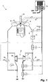
- the Figure 1 shows a reduced system diagram of an internal combustion engine 1 with an exhaust gas turbocharger 2.
- the exhaust gas turbocharger 2 comprises a compressor 3 and a turbine 10.
- the further structure and function of the exhaust gas turbocharger 2 are assumed to be known.
- the air path for supplying combustion air comprises the compressor 3, a charge air cooler 4, a throttle valve 5 and an inlet valve 6 in the cylinder head of the internal combustion engine 1.
- the air path is supplemented by a compressor bypass 7 with a compressor bypass valve 8.
- Via the compressor bypass 7, the charge air is returned from the secondary side of the compressor 3 to the primary side of the compressor 3.
- the exhaust gas path comprises an exhaust valve 9 in the cylinder head of the internal combustion engine 1 and the turbine 10.
- the exhaust gas path is supplemented by a turbine bypass 11 with a turbine bypass valve 12.
- the internal combustion engine 1 is controlled and regulated via an electronic engine control unit 13.
- the following input signals of the electronic engine control unit 13 are shown: a pressure level p1 on the primary side of the compressor 3, an air mass mL on the secondary side of the compressor 3, a pressure level p2 of the charge air, an actual Throttle valve value DK (IST) of the throttle valve 5 and optionally the pressure level pE of the fuel in the injector 14.
- the reference symbol EIN denotes the further input signals, for example an engine speed.
- a first manipulated variable ⁇ VBP for controlling the compressor bypass valve 8
- a second manipulated variable aWG for controlling the turbine bypass valve 12
- a target throttle valve value DK (SL) for controlling the throttle valve 5
- a signal ve for controlling the injector 14, for example a start or end of injection.
- the angular position of the compressor bypass valve 8 is specified via the first manipulated variable ⁇ VBP.
- the angular position of the turbine bypass valve 12 is specified via the second manipulated variable aWG. If a linear actuator is used instead of a flap, then both the first manipulated variable ⁇ VBP and the second manipulated variable aWG correspond to a travel range.
- the further output signals for controlling and regulating the internal combustion engine 1 are identified with the reference symbol AUS, for example the control signal for an intake throttle in a common rail system.
- the Figure 2 shows a block diagram, the individual blocks representing program parts of an executable program.
- the input variables are the target throttle valve value DK (SL), the actual throttle valve value DK (IST), the target air mass mL (SL) and the actual air mass mL (IST).
- the setpoint and actual value of the pressure level of the charge air p2 used.
- the output variables are the first manipulated variable ⁇ VBP for controlling the compressor bypass valve 8 and the second manipulated variable aWG for controlling the turbine bypass valve 12.
- the throttle valve control deviation dDK is calculated from the target / actual deviation of the throttle valve.
- a compressor position controller 16 typically with PID behavior, calculates a first angular value ⁇ 1 from the throttle valve control deviation dDK.
- the first angle value ⁇ 1 is multiplied by a first correction variable KORR1 and then linearized via a function block 18.
- the output value then corresponds to the first manipulated variable ⁇ VBP with which the compressor bypass valve 8 is controlled.
- the compressor position controller 16 has a second signal path for the first angular value al.
- the first angle value ⁇ 1 is multiplied by a second correction variable KORR2 and then linearized via a function block 20.
- the output value corresponds to the second manipulated variable ⁇ WG with which the turbine bypass valve 12 is controlled.
- an air mass control deviation dmL is calculated from the target / actual deviation of the air mass.
- a correction controller 22 typically with PID behavior, then calculates the first correction variable KORR1 from the air mass control deviation.
- the first correction variable KORR1 has a value between zero and one.
- the first correction variable KORR1 has a multiplicative effect on the first angular value ⁇ 1 (multiplication point 17) and thus also determines the first manipulated variable ⁇ VBP.
- the difference to one is formed from the first correction variable KORR1 via a differential element 23.
- the output value corresponds to the second correction variable KORR2, which can also assume a value between zero and one.
- the second correction variable KORR2 has a multiplicative effect on the first angular value ⁇ 1 and thus determines the second manipulated variable ⁇ WG.
- the difference element 23 has the effect that the first manipulated variable ⁇ VBP and the second manipulated variable ⁇ WG achieve an opposite effect. In other words: if the compressor bypass valve is acted upon in the opening direction, the turbine bypass valve is actuated in the closing direction.
- a compressor map 24 is shown.
- the actual air mass mL (IST) is plotted on the abscissa and the compression ratio, i.e. the quotient of the pressure level p2 on the secondary side of the compressor and the pressure level p1 on the primary side of the compressor, is plotted on the ordinate.
- the pumping area is shown hatched, which is limited by the surge line 27.
- the permissible range i.e. outside the pumping range
- fields of constant efficiency are drawn, reference symbols etal and eta2.
- a characteristic curve KL of optimal operating points is laid by these efficiency fields. For example, the operating point BP1 with the value pair mL1 / Q1 lies on this characteristic curve KL.
- a first area 25 is defined by the surge limit and the characteristic curve KL.
- a second area 26 is located to the right of the characteristic curve KL in the direction of larger actual air mass values.
- the operating point BP2 lies in the first area 25 and is defined by the value pair mL2 / Ql.
- the compressor bypass valve is changed in the opening direction and the turbine bypass valve in the closing direction via the correction controller.
- the operating point BP2 changes in the direction of the operating point BP1.
- the operating point BP3 lies in the second area 26 and is defined by the value pair mL3 / Q1.
- the correction controller changes the compressor bypass valve in the closing direction and the turbine bypass valve in the opening direction.
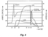
- FIG. 4 shows a timing diagram.
- the first manipulated variable ⁇ VBP for controlling the compressor bypass valve is plotted in degrees and the throttle valve value in percent.
- the second manipulated variable ⁇ WG for controlling the turbine bypass valve is plotted on the right ordinate.
- the following signals are shown over time: the actual throttle valve value DK (IST) as a dashed line, the first manipulated variable ⁇ VBP as a solid line and the second manipulated variable ⁇ WG as a dash-dotted line.
- three different operating states are shown, namely a load connection in the period t1-t3, a steady state in the period t3-t5 and a load shedding in the period t5-t7. Load transfer is initiated at time t1.
- the throttle valve control reacts to this by opening the throttle valve completely, value approx. 80%, followed by an undershoot.
- the throttle valve is then adjusted to the correct setpoint in the period t2 to t3.
- the compressor bypass valve is therefore opened via the correction controller, that is, the correction controller corrects the operating point until it is on the characteristic curve of optimal operating points.
- the course of the first control signal ⁇ VBP reflects these facts.
- the turbine bypass valve now uses the second manipulated variable aWG is applied in the opening direction and the compressor bypass valve is actuated in the closing direction via the first manipulated variable ⁇ VBP.
- the system has then settled at time t4.
- Load shutdown is triggered at time t5.
- the throttle valve is therefore completely closed at time t 6. Since the operating point is now in the first range of the compressor map, the compressor bypass valve is opened completely and the turbine bypass valve is closed. This is marked accordingly in the diagram. After time t7, the system is again in the steady state.
Landscapes
- Engineering & Computer Science (AREA)
- Chemical & Material Sciences (AREA)
- Combustion & Propulsion (AREA)
- Mechanical Engineering (AREA)
- General Engineering & Computer Science (AREA)
- Supercharger (AREA)
Description
- Die Erfindung betrifft ein Regelverfahren gemäß dem Oberbegriff des Anspruchs 1 für eine aufgeladene Brennkraftmaschine, bei dem über die Verstellung eines Verdichter-Bypassventils und eines Turbinen-Bypassventils ein Betriebspunkt im Verdichterkennfeld festgelegt wird.
- Aus der
DE 10 2014 215 180 A1 ist ein Verfahren für eine einstufig aufgeladene Brennkraftmaschine mit einem Verdichter-Bypassventil und einem Turbinen-Bypassventil bekannt. Dem Verfahren zugrunde gelegt ist ein typisches Verdichterkennfeld, welches eine Zuordnung von Luftmassenstrom zu Ladedruck abbildet. Innerhalb des Verdichterkennfelds sind ein nicht zulässiger Arbeitsbereich starken Verdichterpumpens und ein Bereich schwachen Verdichterpumpens dargestellt. Das Verfahren besteht nun darin, dass nach einer Drosselklappen-Freigabe die Lage des Betriebspunkts im Verdichterkennfeld ermittelt wird und in Abhängigkeit hiervon das Verdichter- und das Turbinen-Bypassventil angesteuert werden. Wird beispielsweise festgestellt, dass der Betriebspunkt im Bereich des schwachen Pumpens liegt, so wird das Verdichter-Bypassventil weiter geöffnet und ergänzend das Turbinen-Bypassventil weniger geöffnet. Das Verfahren löst zwar das Problem des Verdichterpumpens nach einer Fahrpedal-Freigabe, ist jedoch zum Beispiel hinsichtlich des Wirkungsgrads noch verbesserungswürdig. -
EP 0 685 638 A2 beschreibt grundsätzlich ein eingangs genanntes Regelverfahren für eine aufgeladene Brennkraftmaschine, bei dem jedenfalls im Prinzip über einen Verdichter-Lageregler ein Betriebspunkt des Verdichters in einem Verdichterkennfeld eingestellt wird, indem über den Verdichter-Lageregler sowohl eine erste Stellgröße zur Ansteuerung des Verdichter-Bypassventils als auch eine zweite Stellgröße zur Ansteuerung des Turbinen-Bypassventils berechnet werden. In dem Verfahren derEP 0 685 638 A2 wird das Verdichter-Bypassventil (Bypass-Valve) und das Turbinen-Bypassventil (Wastegate) gleichzeitig angesteuert, wobei der Betriebspunkt in dem Verdichterkennfeld damit eingestellt wird, dass simultan eine Winkelposition des Verdichter-Bypassventils und des Turbinen-Bypassventils so angepasst wird, dass der Turbolader in dem nierenförmigen Gebiet sogenannter Effizienz-Inseln derFig. 3 derEP 0 685 638 A2 betrieben wird.EP 0 685 638 A2 beschreibt, dass sich der Betriebspunkt innerhalb des Kompressorkennfeldes in Bezug auf die Effizienz-Inseln nach rechts verschiebt, indem das Verdichter-Bypassventil geöffnet wird, um einem Mismatch zwischen Verdichterrad und Turbinenrad im Rahmen von Toleranzen zu begegnen und gleichzeitig einen Betrieb innerhalb der Effizienz-Inseln zu erhalten. Es wird lediglich speziell dazu erläutert, dass unter bestimmten Bedingungen ein Druckverlust im Verdichter auszugleichen sein könnte durch Verringern des Winkels des Turbinen-Bypassventils (Wastegate). -
DE 10 2005 010792 A1 beschreibt lediglich allgemein eine Steuerung von Ventilen der vorgenannten Art.US 2014/316675 A1 beschreibt eine ähnliche Konfiguration mit Verdichter-Bypass und Turbinen-Bypassventil (Wastegate), sowie zwar eine Messung der Luftmasse; die Luftmassenmessung wird aber lediglich zur Bestimmung eines Betriebszustandes verwendet, in welchem Verdichterpumpen möglich sind.FR 2 864 579 A1 - Der Erfindung liegt daher die Aufgabe zugrunde, ein Regelverfahren für eine einstufige aufgeladene Brennkraftmaschine mit einem Verdichter- und einem Turbinen-Bypassventil bei optimiertem Wirkungsgrad zu entwerfen.
- Gelöst wird diese Aufgabe durch eine Regelverfahren mit den Merkmalen von Anspruch 1. Die Ausgestaltungen sind in den Unteransprüchen dargestellt.
- Beim Regelverfahren gemäß der Erfindung wird in Abhängigkeit einer Drosselklappen-Regelabweichung über einen Verdichter-Lageregler ein Betriebspunkt des Verdichters in einem Verdichterkennfeld eingestellt, indem über den Verdichter-Lageregler sowohl eine erste Stellgröße zur Ansteuerung des Verdichter-Bypassventils als auch eine zweite Stellgröße zur Ansteuerung des Turbinen-Bypassventils berechnet werden. Ergänzend wird in Abhängigkeit einer Luftmassen-Regelabweichung über einen Korrekturregler der Betriebspunkt des Verdichters korrigiert, indem über den Korrekturregler sowohl eine erste Korrekturgröße zur Korrektur der ersten Stellgröße als auch eine zweite Korrekturgröße zur Korrektur der zweiten Stellgröße berechnet werden. Über den Korrekturregler wird der Betriebspunkt im Verdichterkennfeld auf eine Kennlinie optimaler Betriebspunkte geregelt. Konkret verläuft die Kennlinie der optimalen Betriebspunkte durch die Felder der bestmöglichen Wirkungsgrade.
- Über die Kennlinie optimaler Betriebspunkte und die Pumpgrenze ist im Verdichterkennfeld ein erster Bereich definiert. Liegt nun zum Beispiel ein Betriebspunkt im ersten Bereich, so wird über den Korrekturregler die Öffnung des Verdichter-Bypassventils vergrößert und die Öffnung des Turbinen-Bypassventils verringert. Die vom Korrekturregler berechneten Korrekturgrößen wirken folglich gegenläufig auf die beiden Stellgrößen ein.
- Die Erfindung gestattet ein einstufiges Aufladekonzept mit einem kleinen Abgasturbolader nebst kleiner Turbine. Da sich in nahezu allen Betriebspunkten ein Ladedrucküberschuss bis hinauf zu Volllastkurve ergibt, wird dieser zunächst über die Drosselklappe abgedrosselt. Aufgrund der hohen Druckverhältnisse am Verdichter ist eine reine Drosselklappen-Regelung nicht möglich, so dass der überschüssige Ladedruck über das Verdichter-Bypassventil und das Turbinen-Bypassventil abgesteuert wird. Erst dadurch kann ein Pumpen in unteren Drehzahlbereich und ein Stopfen des Verdichters im oberen Drehzahlbereich vermieden werden. Von Vorteil ist daher, dass mit einer einstufigen Aufladung ein breites Verdichterkennfeld darstellbar ist.
- Aufgrund der Luftmassen-Regelung reagiert das Regelverfahren automatisch richtig auf Änderungen der Umgebungsbedingung, wie etwa die geodätische Höhe oder die Umgebungstemperatur. Hervorzuheben ist der geringe Bedatungsaufwand von nur einem Kennfeld. Indem der Verdichter-Lageregler sowohl auf das Verdichter-Bypassventil als auch auf das Turbinen-Bypassventil zugreift, ist ein stetiger Übergang gewährleistet. Zudem werden Transientvorgänge richtig interpretiert, so wird zum Beispiel bei einer Lastaufschaltung der fehlenden Drosselklappen-Reserve dadurch begegnet, dass das Verdichter-Bypassventil und das Turbinen-Bypassventil geschlossen werden. Einsetzbar ist das Verfahren sowohl bei einem Dieselmotor als auch einem Gasmotor.
- In den Figuren ist ein bevorzugtes Ausführungsbeispiel dargestellt. Es zeigen:
- Figur 1
- ein Systemschaubild,
- Figur 2
- ein Blockschaltbild,
- Figur 3
- ein Verdichterkennfeld und
- Figur 4
- ein Zeitdiagramm.
- Die
Figur 1 zeigt ein reduziertes Systemschaubild einer Brennkraftmaschine 1 mit einem Abgasturbolader 2. Der Abgasturbolader 2 umfasst einen Verdichter 3 und eine Turbine 10. Der weitere Aufbau und die Funktion des Abgasturboladers 2 werden als bekannt vorausgesetzt. Der Luftpfad zur Zuführung von Verbrennungsluft umfasst den Verdichter 3, einen Ladeluftkühler 4, eine Drosselklappe 5 und ein Einlassventil 6 im Zylinderkopf der Brennkraftmaschine 1. Ergänzt wird der Luftpfad durch einen Verdichter-Bypass 7 mit einem Verdichter-Bypassventil 8. Über den Verdichter-Bypass 7 wird die Ladeluft von der Sekundärseite des Verdichters 3 auf die Primärseite des Verdichters 3 zurückgeführt. Der Abgaspfad umfasst ein Auslassventil 9 im Zylinderkopf der Brennkraftmaschine 1 und die Turbine 10. Ergänzt wird der Abgaspfad durch einen Turbinen-Bypass 11 mit einem Turbinen-Bypassventil 12. - Gesteuert und geregelt wird die Brennkraftmaschine 1 über ein elektronisches Motorsteuergerät 13. Als Eingangssignale des elektronischen Motorsteuergeräts 13 sind dargestellt: ein Druckniveau p1 der Primärseite des Verdichters 3, eine Luftmasse mL auf der Sekundärseite des Verdichters 3, ein Druckniveau p2 der Ladeluft, ein Ist-Drosselklappenwert DK(IST) der Drosselklappe 5 und optional das Druckniveau pE des Kraftstoffes im Injektor 14. Mit dem Bezugszeichen EIN sind die weiteren Eingangssignale bezeichnet, beispielsweise eine Motordrehzahl. Als Ausgangssignale des elektronischen Motorsteuergeräts 13 sind in der
Figur 1 dargestellt: ein erste Stellgröße αVBP zur Ansteuerung des Verdichter-Bypassventils 8, ein zweites Stellgröße aWG zur Ansteuerung des Turbinen-Bypassventils 12, ein Soll-Drosselklappenwert DK(SL) zur Ansteuerung der Drosselklappe 5 und ein Signal ve zur Ansteuerung des Injektors 14, beispielsweise ein Spritzbeginn oder Spritzende. Über die erste Stellgröße αVBP wird die Winkellage des Verdichter-Bypassventils 8 vorgegeben. Über die zweite Stellgröße aWG wird die Winkellage des Turbinen-Bypassventils 12 vorgegeben. Wird anstelle einer Klappe ein lineares Stellglied verwendet, dann entsprechen sowohl die erste Stellgröße αVBP als auch die zweite Stellgröße aWG einem Stellweg. Mit dem Bezugszeichen AUS sind die weiteren Augangssignale zur Steuerung und Regelung der Brennkraftmaschine 1 gekennzeichnet, beispielsweise das Stellsignal für eine Saugdrossel bei einem Common-Railsystem. - Die
Figur 2 zeigt ein Blockschaltbild, wobei die einzelnen Blöcke Programmteile eines ausführbaren Programms darstellen. Die Eingangsgrößen sind der Soll-Drosselklappenwert DK(SL), der Ist-Drosselklappenwert DK(IST), die Soll-Luftmasse mL(SL) und die Ist-Luftmasse mL(IST). Bei einem Dieselmotor ohne Drosselklappensteuerung wird anstelle der Drosselklappenwerte dann der Soll- und Istwert des Druckniveaus der Ladeluft p2 verwendet. Die Ausgangsgrößen sind die erste Stellgröße αVBP zur Ansteuerung des Verdichter-Bypassventils 8 und die zweite Stellgröße aWG zur Ansteuerung des Turbinen-Bypassventils 12. An einem Summationspunkt 15 wird aus der Soll-Istabweichung der Drosselklappe die Drosselklappen-Regelabweichung dDK berechnet. Aus der Drosselklappen-Regelabweichung dDK berechnet ein Verdichter-Lageregler 16, typischerweise mit PID-Verhalten, einen ersten Winkelwert α1. An einem Multiplikationspunkt 17 wird der erste Winkelwert α1 mit einer ersten Korrekturgröße KORR1 multipliziert und anschließend über eine Funktionsblock 18 linearisiert. Der Ausgangswert entspricht dann der ersten Stellgröße αVBP, mit welcher das Verdichter-Bypassventil 8 angesteuert wird. Der Verdichter-Lageregler 16 besitzt einen zweiten Signalpfad für den ersten Winkelwert al. An einem Multiplikationspunkt 19 wird der erste Winkelwert α1 mit einer zweiten Korrekturgröße KORR2 multipliziert und anschließend über eine Funktionsblock 20 linearisiert. Der Ausgangswert entspricht der zweiten Stellgröße αWG, mit welcher das Turbinen-Bypassventil 12 angesteuert wird. - An einem Summationspunkt 21 wird aus der Soll-Istabweichung der Luftmasse eine Luftmassen-Regelabweichung dmL berechnet. Aus der Luftmassen-Regelabweichung berechnet dann ein Korrekturregler 22, typischerweise mit PID-Verhalten, die erste Korrekturgröße KORR1. Die erste Korrekturgröße KORR1 hat einen Wert zwischen Null und Eins. Die erste Korrekturgröße KORR1 wirkt multiplikativ auf die ersten Winkelwert α1 (Multiplikationspunkt 17) ein und bestimmt damit auch die erste Stellgröße αVBP. Aus der ersten Korrekturgröße KORR1 wird über ein Differenzglied 23 die Differenz zu Eins gebildet. Der Ausgangswert entspricht der zweiten Korrekturgröße KORR2, welche ebenfalls einen Wert zwischen Null und Eins annehmen kann. Die zweite Korrekturgröße KORR2 wirkt multiplikativ auf den ersten Winkelwert α1 ein und bestimmt damit die zweite Stellgröße αWG. Über das Differenzglied 23 wird bewirkt, dass die erste Stellgröße αVBP und die zweite Stellgröße αWG eine gegenläufige Wirkung erzielen. Mit anderen Worten: wird zum Beispiel der Verdichter-Bypassventil in Öffnungsrichtung beaufschlagt, so wird das Turbinen-Bypassventil in Schließrichtung betätigt.
- In der
Figur 3 ist ein Verdichterkennfeld 24 dargestellt. Auf der Abszisse ist die Ist-Luftmasse mL(IST) und auf der Ordinate ist das Verdichtungsverhältnis, also der Quotient aus dem Druckniveaus p2 auf der Sekundärseite des Verdichters und des Druckniveaus p1 auf der Primärseite des Verdichters aufgetragen. Schraffiert dargestellt ist der Pumpbereich, welcher durch die Pumpgrenze 27 begrenzt wird. Im zulässigen Bereich, also außerhalb des Pumpbereichs, sind Felder konstanten Wirkungsgrads eingezeichnet, Bezugszeichen etal und eta2. Durch diese Wirkungsgradfelder ist eine Kennlinie KL optimaler Betriebspunkte gelegt. So liegt beispielsweise der Betriebspunkt BP1 mit dem Wertepaar mL1/Q1 auf dieser Kennlinie KL. Durch die Pumpgrenze und die Kennlinie KL wird ein erster Bereich 25 definiert. Ein zweiter Bereich 26 befindet sich rechts der Kennlinie KL in Richtung größerer Ist-Luftmassenwerte. Der Betriebspunkt BP2 liegt im ersten Bereich 25 und ist über das Wertepaar mL2/Ql definiert. In diesem Fall wird über den Korrekturregler das Verdichter-Bypassventil in Öffnungsrichtung und das Turbinen-Bypassventil in Schließrichtung verändert. Als Folge davon verändert sich der Betriebspunkt BP2 in Richtung auf den Betriebspunkt BP1. Der Betriebspunkt BP3 liegt im zweiten Bereich 26 und ist durch das Wertepaar mL3/Ql definiert. In diesem Fall wird über den Korrekturregler das Verdichter-Bypassventil in Schließrichtung und das Turbinen-Bypassventil in Öffnungsrichtung verändert. - In der
Figur 4 zeigt ein Zeitdiagramm. Auf der linken Ordinate sind die erste Stellgröße αVBP zur Ansteuerung des Verdichter-Bypassventils in Grad und der Drosselklappenwert in Prozent aufgetragen. Auf der rechten Ordinate ist die zweite Stellgröße αWG zur Ansteuerung des Turbinen-Bypassventils aufgetragen. Über der Zeit sind folgende Signale dargestellt: der Ist-Drosselklappenwert DK(IST) als gestrichelte Linie, die erste Stellgröße αVBP als durchgezogene Linie und die zweite Stellgröße αWG als strichpunktierte Linie. Im Zeitdiagramm sind drei unterschiedliche Betriebszustände dargestellt, nämlich eine Lastaufschaltung im Zeitraum t1-t3, ein eingeschwungener Zustand im Zeitraum t3-t5 und ein Lastabwurf im Zeitraum t5-t7. Zum Zeitpunkt t1 wird eine Lastaufschaltung initiiert. Die Drosselklappenregelung reagiert hierauf mit einem vollständigen Öffnen der Drosselklappe, Wert ca. 80%, gefolgt von einem Unterschwingen. Im Zeitraum t2 bis t3 wird dann die Drosselklappe auf den korrekten Sollwert eingeregelt. Zum Zeitpunkt t2 wird festgestellt, dass der Betriebspunkt im Verdichterkennfeld im ersten Bereich liegt (Fig. 3 : BP2). Über den Korrekturregler wird daher das Verdichter-Bypassventil geöffnet, das heißt, der Korrekturregler korrigiert den Betriebspunkt so lange bis dieser auf der Kennlinie optimaler Betriebspunkte liegt. Der Verlauf des ersten Stellsignals αVBP spiegelt diesen Sachverhalt wieder. Beim dargestellten Beispiel wird nun davon ausgegangen, dass ab dem Zeitpunkt t3 der Betriebspunkt im zweiten Bereich des Verdichterkennfelds liegt. Hierauf reagiert der Korrekturregler indem nunmehr das Turbinen-Bypassventil über die zweite Stellgröße aWG in Öffnungsrichtung beaufschlagt wird und das Verdichter-Bypassventil über die erste Stellgröße αVBP in Schließrichtung betätigt wird. Zum Zeitpunkt t4 ist dann das System eingeschwungen. - Zum Zeitpunkt t5 wird eine Lastabschaltung ausgelöst. Daher wird zum Zeitpunkt t 6 die Drosselklappe vollständig geschlossen. Da nunmehr der Betriebspunkt im ersten Bereich des Verdichterkennfelds liegt, wird das Verdichter-Bypassventil vollständig geöffnet und das Turbinen-Bypassventil geschlossen. Im Diagramm ist dies entsprechend gekennzeichnet. Nach dem Zeitpunkt t7 ist das System wieder im eingeschwungenen Zustand.
-
- 1
- Brennkraftmaschine
- 2
- Abgasturbolader
- 3
- Verdichter
- 4
- Ladeluftkühler
- 5
- Drosselklappe
- 6
- Einlassventil
- 7
- Verdichter-Bypass
- 8
- Verdichter-Bypassventil
- 9
- Auslassventil
- 10
- Turbine
- 11
- Turbinen-Bypass
- 12
- Turbinen-Bypassventil
- 13
- Elektronisches Motorsteuergerät (ECU)
- 14
- Injektor
- 15
- Summationspunkt
- 16
- Verdichter-Lageregler
- 17
- Multiplikationspunkt
- 18
- Funktionsblock
- 19
- Multiplikationspunkt
- 20
- Funktionsblock
- 21
- Summationspunkt
- 22
- Korrekturregler
- 23
- Differenzglied
- 24
- Verdichterkennfeld
- 25
- Erster Bereich (Verdichterkennfeld)
- 26
- Zweiter Bereich (Verdichterkennfeld)
- 27
- Pumpgrenze
Claims (4)
- Regelverfahren für eine aufgeladene Brennkraftmaschine (1), wobei in dem Regelverfahren in Abhängigkeit einer Drosselklappen-Regelabweichung (dDK) über einen Verdichter-Lageregler (16) ein Betriebspunkt des Verdichters (3) in einem Verdichterkennfeld (24) eingestellt wird, indem über den Verdichter-Lageregler (16) sowohl eine erste Stellgröße (αVBP) zur Ansteuerung des Verdichter-Bypassventils (8) als auch eine zweite Stellgröße (αWG) zur Ansteuerung des Turbinen-Bypassventils (12) berechnet werden dadurch gekennzeichnet, dass
in dem Regelverfahren in Abhängigkeit einer Luftmassen-Regelabweichung (dmL) über einen Korrekturregler (22) der Betriebspunkt des Verdichters (3) korrigiert wird, indem über den Korrekturregler (22) sowohl eine erste Korrekturgröße (KORR1) zur Korrektur der ersten Stellgröße (αVBP) als auch eine zweite Korrekturgröße (KORR2) zur Korrektur der zweiten Stellgröße (αWG) berechnet werden. - Verfahren nach Anspruch 1, dadurch gekennzeichnet, dass der Betriebspunkt im Verdichterkennfeld (24) über den Korrekturregler (22) auf eine Kennlinie (KL) optimaler Betriebspunkte geregelt wird.
- Verfahren nach Anspruch 2, dadurch gekennzeichnet, dass ein erster Bereich (25) im Verdichterkennfeld (24) über die Kennlinie (KL) und eine Pumpgrenze (27) definiert wird und bei einem Betriebspunkt im ersten Bereich (25) über den Korrekturregler (22) die Öffnung des Verdichter-Bypassventils (8) vergrößert sowie die Öffnung des Turbinen-Bypassventils (12) verringert wird.
- Verfahren nach Anspruch 3, dadurch gekennzeichnet, dass bei einem Betriebspunkt in einem zweiten Bereich (26) des Verdichterkennfelds (24) über den Korrekturregler (22) die Öffnung des Verdichter-Bypassventils (8) verringert und die Öffnung des Turbinen-Bypassventils (12) vergrößert wird.
Applications Claiming Priority (2)
| Application Number | Priority Date | Filing Date | Title |
|---|---|---|---|
| DE102016011305.7A DE102016011305B3 (de) | 2016-09-19 | 2016-09-19 | Regelverfahren für eine aufgeladene Brennkraftmaschine |
| PCT/EP2017/000840 WO2018050265A1 (de) | 2016-09-19 | 2017-07-13 | Regelverfahren für eine aufgeladene brennkraftmaschine |
Publications (2)
| Publication Number | Publication Date |
|---|---|
| EP3516194A1 EP3516194A1 (de) | 2019-07-31 |
| EP3516194B1 true EP3516194B1 (de) | 2020-10-14 |
Family
ID=59337614
Family Applications (1)
| Application Number | Title | Priority Date | Filing Date |
|---|---|---|---|
| EP17739474.9A Active EP3516194B1 (de) | 2016-09-19 | 2017-07-13 | Regelverfahren für eine aufgeladene brennkraftmaschine |
Country Status (6)
| Country | Link |
|---|---|
| US (1) | US11635034B2 (de) |
| EP (1) | EP3516194B1 (de) |
| CN (1) | CN109690055B (de) |
| DE (1) | DE102016011305B3 (de) |
| ES (1) | ES2843554T3 (de) |
| WO (1) | WO2018050265A1 (de) |
Family Cites Families (30)
| Publication number | Priority date | Publication date | Assignee | Title |
|---|---|---|---|---|
| US4220993A (en) * | 1978-09-15 | 1980-09-02 | Sperry Corporation | Engine throttle control system |
| US4346776A (en) * | 1979-02-23 | 1982-08-31 | The Bendix Corporation | Means for improving automobile driveability |
| US4337839A (en) * | 1979-02-23 | 1982-07-06 | The Bendix Corporation | Means for improving automobile driveability |
| US5551236A (en) * | 1994-05-02 | 1996-09-03 | Dresser Industries, Inc. | Turbocharger control management system |
| US8215292B2 (en) * | 1996-07-17 | 2012-07-10 | Bryant Clyde C | Internal combustion engine and working cycle |
| US6041273A (en) * | 1997-07-01 | 2000-03-21 | The United States Of America As Represented By The Administrator Of The National Aeronautics And Space Administration | Emergency control aircraft system using thrust modulation |
| FR2864579B1 (fr) | 2003-12-24 | 2006-02-17 | Renault Sas | Moteur a combustion interne avec suralimentation pilotee et procede de pilotage de la suralimentation |
| DE102005010792A1 (de) * | 2005-03-09 | 2006-09-14 | Robert Bosch Gmbh | Brennkraftmaschine und Verfahren zum Betreiben einer Brennkraftmaschine |
| US8001778B2 (en) * | 2007-09-25 | 2011-08-23 | Ford Global Technologies, Llc | Turbocharged engine control operation with adjustable compressor bypass |
| US8001782B2 (en) * | 2007-09-26 | 2011-08-23 | Ford Global Technologies, Llc | Approach for identifying and responding to an unresponsive wastegate in a twin turbocharged engine |
| US8616181B2 (en) * | 2008-07-11 | 2013-12-31 | Tula Technology, Inc. | Internal combustion engine control for improved fuel efficiency |
| US8701628B2 (en) * | 2008-07-11 | 2014-04-22 | Tula Technology, Inc. | Internal combustion engine control for improved fuel efficiency |
| CN102395771B (zh) * | 2009-07-16 | 2013-09-04 | 丰田自动车株式会社 | 内燃机的控制阀异常判断装置 |
| US8397499B2 (en) * | 2009-08-24 | 2013-03-19 | Ford Global Technologies, Llc | Methods and systems for turbocharger control |
| CN103518047B (zh) * | 2011-04-18 | 2016-08-31 | 丰田自动车株式会社 | 增压发动机的控制装置 |
| US9890718B2 (en) * | 2012-01-11 | 2018-02-13 | Toyota Jidosha Kabushiki Kaisha | Control apparatus for internal combustion engine |
| US9273619B2 (en) * | 2012-12-10 | 2016-03-01 | Fca Us Llc | Supercharged engine and method of control |
| WO2014146068A1 (en) * | 2013-03-15 | 2014-09-18 | Larimore Wallace | A method and system of dynamic model identification for monitoring and control of dynamic machines with variable structure or variable operation conditions |
| US9389198B2 (en) * | 2013-04-18 | 2016-07-12 | Ford Global Technologies, Llc | Humidity sensor and engine system |
| US20140316675A1 (en) | 2013-04-18 | 2014-10-23 | Ford Global Technologies, Llc | Preserving combustion stability during compressor-surge conditions |
| US10417353B2 (en) * | 2013-06-14 | 2019-09-17 | Wallace LARIMORE | Method and system of dynamic model identification for monitoring and control of dynamic machines with variable structure or variable operation conditions |
| US9080506B2 (en) * | 2013-08-13 | 2015-07-14 | Ford Global Technologies, Llc | Methods and systems for boost control |
| JP6434285B2 (ja) * | 2013-12-04 | 2018-12-05 | 三菱重工業株式会社 | 過給システムの制御装置 |
| US9677481B2 (en) * | 2015-06-16 | 2017-06-13 | Ford Global Technologies, Llc | Methods and systems for boost control |
| JP6394529B2 (ja) * | 2015-07-29 | 2018-09-26 | マツダ株式会社 | エンジンの制御装置 |
| US10119479B2 (en) * | 2015-08-06 | 2018-11-06 | Ford Global Technologies, Llc | Methods and systems for boost control based on exhaust pressure greater than a threshold |
| DE102015219337A1 (de) * | 2015-10-07 | 2017-04-13 | Robert Bosch Gmbh | Verfahren und Vorrichtung zum Betreiben einer Antriebsvorrichtung, Antriebsvorrichtung |
| US10208693B2 (en) * | 2015-10-28 | 2019-02-19 | Ford Global Technologies, Llc | Method and system to mitigate throttle degradation |
| JP6344438B2 (ja) * | 2016-08-05 | 2018-06-20 | トヨタ自動車株式会社 | 内燃機関の制御装置 |
| JP6227086B1 (ja) * | 2016-10-11 | 2017-11-08 | 三菱電機株式会社 | 過給機付き内燃機関の制御装置及び制御方法 |
-
2016
- 2016-09-19 DE DE102016011305.7A patent/DE102016011305B3/de not_active Expired - Fee Related
-
2017
- 2017-07-13 WO PCT/EP2017/000840 patent/WO2018050265A1/de not_active Ceased
- 2017-07-13 CN CN201780057687.4A patent/CN109690055B/zh active Active
- 2017-07-13 ES ES17739474T patent/ES2843554T3/es active Active
- 2017-07-13 EP EP17739474.9A patent/EP3516194B1/de active Active
- 2017-07-13 US US16/328,970 patent/US11635034B2/en active Active
Non-Patent Citations (1)
| Title |
|---|
| None * |
Also Published As
| Publication number | Publication date |
|---|---|
| DE102016011305B3 (de) | 2018-02-15 |
| WO2018050265A1 (de) | 2018-03-22 |
| CN109690055A (zh) | 2019-04-26 |
| EP3516194A1 (de) | 2019-07-31 |
| US11635034B2 (en) | 2023-04-25 |
| ES2843554T3 (es) | 2021-07-19 |
| US20190277209A1 (en) | 2019-09-12 |
| CN109690055B (zh) | 2022-03-08 |
Similar Documents
| Publication | Publication Date | Title |
|---|---|---|
| EP1179128B1 (de) | Verfahren und vorrichtung zur regelung des ladedrucks einer brennkraftmaschine | |
| EP2534353B1 (de) | Aufgeladene brennkraftmaschine | |
| DE102007000236B4 (de) | Abgasrezirkulationsgerät für einen Verbrennungsmotor und Verfahren für ein Steuern desselben | |
| EP1809876B1 (de) | Verfahren und vorrichtung zur steuerung oder regelung des ladedrucks einer brennkraftmaschine mit einem verdichter | |
| DE102004056894A1 (de) | Verfahren und Vorrichtung zur Regelung des Ladedrucks einer Brennkraftmaschine | |
| DE102011017036B4 (de) | Verfahren zur Regelung der NOx-Konzentration im Abgas einer Brennkraftmaschine | |
| DE102010043897B4 (de) | Verfahren und Vorrichtung zum Betreiben eines Verbrennungsmotors | |
| DE102015111713B4 (de) | Steuerbetrieb-Abweichungskompensationsverfahren eines Turboladers | |
| EP3698032A1 (de) | Verfahren zur modellbasierten steuerung und regelung einer brennkraftmaschine | |
| DE102015216261A1 (de) | Verfahren und Vorrichtung zum Ermitteln einer Stellgröße für einen Ladersteller einer abgasgetriebenen Aufladeeinrichtung | |
| EP3594480B1 (de) | Verfahren zur steuerung eines aufladungssystems | |
| DE102004003378B4 (de) | Regelungs- und Steuerungsvorrichtung und Regelungs- und Steuerungsverfahren für einen mehrstufigen Turbolader | |
| DE4103361C2 (de) | ||
| EP2923073B1 (de) | Verfahren zum betrieb einer fremdgezündeten brennkraftmaschine mit einem abgasturbolader | |
| EP3543514B1 (de) | Verfahren und regelkreis zum bestimmen einer stellgrösse zum einstellen eines saugrohrdrucks | |
| DE102010038326A1 (de) | Erhöhung des Abgasrückführstroms oder der Abgasrückführrate bei bereits offenem Abgasrückführventil | |
| DE102011081949B4 (de) | Verfahren und Vorrichtung zur Durchführung einer Regelung, insbesondere zum Einsatz in einem Kraftfahrzeug | |
| EP3516194B1 (de) | Regelverfahren für eine aufgeladene brennkraftmaschine | |
| DE102014224534B4 (de) | Verfahren zum Betreiben einer Brennkraftmaschine | |
| WO2016142110A1 (de) | Verfahren zur momentenneutralen umschaltung von betriebszuständen eines aktuators einer brennkraftmaschine | |
| EP0728922B1 (de) | Luftmassenregler für eine turboaufgeladene Brennkraftmaschine mit angepasstem I-Anteil | |
| DE102005023260A1 (de) | Verfahren zur Regelung eines Abgasturboladers | |
| EP1672203B1 (de) | Verfahren und Vorrichtung zur Motorsteuerung bei einem Kraftfahrzeug | |
| DE102008032250A1 (de) | Verfahren zur Regelung der Abgasrückführung einer Verbrennungskraftmaschine | |
| DE102017221625B3 (de) | Verfahren zum Steuern eines Verbrennungsmotors im einstufigen Betriebsbereich eines mehrstufigen Aufladesystems |
Legal Events
| Date | Code | Title | Description |
|---|---|---|---|
| STAA | Information on the status of an ep patent application or granted ep patent |
Free format text: STATUS: UNKNOWN |
|
| STAA | Information on the status of an ep patent application or granted ep patent |
Free format text: STATUS: THE INTERNATIONAL PUBLICATION HAS BEEN MADE |
|
| PUAI | Public reference made under article 153(3) epc to a published international application that has entered the european phase |
Free format text: ORIGINAL CODE: 0009012 |
|
| STAA | Information on the status of an ep patent application or granted ep patent |
Free format text: STATUS: REQUEST FOR EXAMINATION WAS MADE |
|
| 17P | Request for examination filed |
Effective date: 20190423 |
|
| AK | Designated contracting states |
Kind code of ref document: A1 Designated state(s): AL AT BE BG CH CY CZ DE DK EE ES FI FR GB GR HR HU IE IS IT LI LT LU LV MC MK MT NL NO PL PT RO RS SE SI SK SM TR |
|
| AX | Request for extension of the european patent |
Extension state: BA ME |
|
| DAV | Request for validation of the european patent (deleted) | ||
| DAX | Request for extension of the european patent (deleted) | ||
| GRAP | Despatch of communication of intention to grant a patent |
Free format text: ORIGINAL CODE: EPIDOSNIGR1 |
|
| STAA | Information on the status of an ep patent application or granted ep patent |
Free format text: STATUS: GRANT OF PATENT IS INTENDED |
|
| INTG | Intention to grant announced |
Effective date: 20200508 |
|
| GRAS | Grant fee paid |
Free format text: ORIGINAL CODE: EPIDOSNIGR3 |
|
| GRAA | (expected) grant |
Free format text: ORIGINAL CODE: 0009210 |
|
| STAA | Information on the status of an ep patent application or granted ep patent |
Free format text: STATUS: THE PATENT HAS BEEN GRANTED |
|
| AK | Designated contracting states |
Kind code of ref document: B1 Designated state(s): AL AT BE BG CH CY CZ DE DK EE ES FI FR GB GR HR HU IE IS IT LI LT LU LV MC MK MT NL NO PL PT RO RS SE SI SK SM TR |
|
| REG | Reference to a national code |
Ref country code: GB Ref legal event code: FG4D Free format text: NOT ENGLISH |
|
| REG | Reference to a national code |
Ref country code: AT Ref legal event code: REF Ref document number: 1323833 Country of ref document: AT Kind code of ref document: T Effective date: 20201015 Ref country code: CH Ref legal event code: EP |
|
| REG | Reference to a national code |
Ref country code: CH Ref legal event code: NV Representative=s name: BOVARD AG PATENT- UND MARKENANWAELTE, CH |
|
| REG | Reference to a national code |
Ref country code: DE Ref legal event code: R096 Ref document number: 502017007762 Country of ref document: DE |
|
| REG | Reference to a national code |
Ref country code: IE Ref legal event code: FG4D Free format text: LANGUAGE OF EP DOCUMENT: GERMAN |
|
| REG | Reference to a national code |
Ref country code: NL Ref legal event code: MP Effective date: 20201014 |
|
| PG25 | Lapsed in a contracting state [announced via postgrant information from national office to epo] |
Ref country code: FI Free format text: LAPSE BECAUSE OF FAILURE TO SUBMIT A TRANSLATION OF THE DESCRIPTION OR TO PAY THE FEE WITHIN THE PRESCRIBED TIME-LIMIT Effective date: 20201014 Ref country code: GR Free format text: LAPSE BECAUSE OF FAILURE TO SUBMIT A TRANSLATION OF THE DESCRIPTION OR TO PAY THE FEE WITHIN THE PRESCRIBED TIME-LIMIT Effective date: 20210115 Ref country code: NO Free format text: LAPSE BECAUSE OF FAILURE TO SUBMIT A TRANSLATION OF THE DESCRIPTION OR TO PAY THE FEE WITHIN THE PRESCRIBED TIME-LIMIT Effective date: 20210114 Ref country code: PT Free format text: LAPSE BECAUSE OF FAILURE TO SUBMIT A TRANSLATION OF THE DESCRIPTION OR TO PAY THE FEE WITHIN THE PRESCRIBED TIME-LIMIT Effective date: 20210215 Ref country code: RS Free format text: LAPSE BECAUSE OF FAILURE TO SUBMIT A TRANSLATION OF THE DESCRIPTION OR TO PAY THE FEE WITHIN THE PRESCRIBED TIME-LIMIT Effective date: 20201014 |
|
| REG | Reference to a national code |
Ref country code: LT Ref legal event code: MG4D |
|
| PG25 | Lapsed in a contracting state [announced via postgrant information from national office to epo] |
Ref country code: BG Free format text: LAPSE BECAUSE OF FAILURE TO SUBMIT A TRANSLATION OF THE DESCRIPTION OR TO PAY THE FEE WITHIN THE PRESCRIBED TIME-LIMIT Effective date: 20210114 Ref country code: PL Free format text: LAPSE BECAUSE OF FAILURE TO SUBMIT A TRANSLATION OF THE DESCRIPTION OR TO PAY THE FEE WITHIN THE PRESCRIBED TIME-LIMIT Effective date: 20201014 Ref country code: LV Free format text: LAPSE BECAUSE OF FAILURE TO SUBMIT A TRANSLATION OF THE DESCRIPTION OR TO PAY THE FEE WITHIN THE PRESCRIBED TIME-LIMIT Effective date: 20201014 Ref country code: IS Free format text: LAPSE BECAUSE OF FAILURE TO SUBMIT A TRANSLATION OF THE DESCRIPTION OR TO PAY THE FEE WITHIN THE PRESCRIBED TIME-LIMIT Effective date: 20210214 Ref country code: SE Free format text: LAPSE BECAUSE OF FAILURE TO SUBMIT A TRANSLATION OF THE DESCRIPTION OR TO PAY THE FEE WITHIN THE PRESCRIBED TIME-LIMIT Effective date: 20201014 |
|
| PG25 | Lapsed in a contracting state [announced via postgrant information from national office to epo] |
Ref country code: NL Free format text: LAPSE BECAUSE OF FAILURE TO SUBMIT A TRANSLATION OF THE DESCRIPTION OR TO PAY THE FEE WITHIN THE PRESCRIBED TIME-LIMIT Effective date: 20201014 Ref country code: HR Free format text: LAPSE BECAUSE OF FAILURE TO SUBMIT A TRANSLATION OF THE DESCRIPTION OR TO PAY THE FEE WITHIN THE PRESCRIBED TIME-LIMIT Effective date: 20201014 |
|
| REG | Reference to a national code |
Ref country code: DE Ref legal event code: R097 Ref document number: 502017007762 Country of ref document: DE |
|
| REG | Reference to a national code |
Ref country code: ES Ref legal event code: FG2A Ref document number: 2843554 Country of ref document: ES Kind code of ref document: T3 Effective date: 20210719 |
|
| PG25 | Lapsed in a contracting state [announced via postgrant information from national office to epo] |
Ref country code: SM Free format text: LAPSE BECAUSE OF FAILURE TO SUBMIT A TRANSLATION OF THE DESCRIPTION OR TO PAY THE FEE WITHIN THE PRESCRIBED TIME-LIMIT Effective date: 20201014 Ref country code: LT Free format text: LAPSE BECAUSE OF FAILURE TO SUBMIT A TRANSLATION OF THE DESCRIPTION OR TO PAY THE FEE WITHIN THE PRESCRIBED TIME-LIMIT Effective date: 20201014 Ref country code: CZ Free format text: LAPSE BECAUSE OF FAILURE TO SUBMIT A TRANSLATION OF THE DESCRIPTION OR TO PAY THE FEE WITHIN THE PRESCRIBED TIME-LIMIT Effective date: 20201014 Ref country code: EE Free format text: LAPSE BECAUSE OF FAILURE TO SUBMIT A TRANSLATION OF THE DESCRIPTION OR TO PAY THE FEE WITHIN THE PRESCRIBED TIME-LIMIT Effective date: 20201014 Ref country code: RO Free format text: LAPSE BECAUSE OF FAILURE TO SUBMIT A TRANSLATION OF THE DESCRIPTION OR TO PAY THE FEE WITHIN THE PRESCRIBED TIME-LIMIT Effective date: 20201014 Ref country code: SK Free format text: LAPSE BECAUSE OF FAILURE TO SUBMIT A TRANSLATION OF THE DESCRIPTION OR TO PAY THE FEE WITHIN THE PRESCRIBED TIME-LIMIT Effective date: 20201014 |
|
| PLBE | No opposition filed within time limit |
Free format text: ORIGINAL CODE: 0009261 |
|
| STAA | Information on the status of an ep patent application or granted ep patent |
Free format text: STATUS: NO OPPOSITION FILED WITHIN TIME LIMIT |
|
| PG25 | Lapsed in a contracting state [announced via postgrant information from national office to epo] |
Ref country code: DK Free format text: LAPSE BECAUSE OF FAILURE TO SUBMIT A TRANSLATION OF THE DESCRIPTION OR TO PAY THE FEE WITHIN THE PRESCRIBED TIME-LIMIT Effective date: 20201014 |
|
| 26N | No opposition filed |
Effective date: 20210715 |
|
| PG25 | Lapsed in a contracting state [announced via postgrant information from national office to epo] |
Ref country code: AL Free format text: LAPSE BECAUSE OF FAILURE TO SUBMIT A TRANSLATION OF THE DESCRIPTION OR TO PAY THE FEE WITHIN THE PRESCRIBED TIME-LIMIT Effective date: 20201014 Ref country code: IT Free format text: LAPSE BECAUSE OF FAILURE TO SUBMIT A TRANSLATION OF THE DESCRIPTION OR TO PAY THE FEE WITHIN THE PRESCRIBED TIME-LIMIT Effective date: 20201014 |
|
| PG25 | Lapsed in a contracting state [announced via postgrant information from national office to epo] |
Ref country code: SI Free format text: LAPSE BECAUSE OF FAILURE TO SUBMIT A TRANSLATION OF THE DESCRIPTION OR TO PAY THE FEE WITHIN THE PRESCRIBED TIME-LIMIT Effective date: 20201014 |
|
| PG25 | Lapsed in a contracting state [announced via postgrant information from national office to epo] |
Ref country code: MC Free format text: LAPSE BECAUSE OF FAILURE TO SUBMIT A TRANSLATION OF THE DESCRIPTION OR TO PAY THE FEE WITHIN THE PRESCRIBED TIME-LIMIT Effective date: 20201014 |
|
| REG | Reference to a national code |
Ref country code: BE Ref legal event code: MM Effective date: 20210731 |
|
| REG | Reference to a national code |
Ref country code: DE Ref legal event code: R081 Ref document number: 502017007762 Country of ref document: DE Owner name: ROLLS-ROYCE SOLUTIONS GMBH, DE Free format text: FORMER OWNER: MTU FRIEDRICHSHAFEN GMBH, 88045 FRIEDRICHSHAFEN, DE |
|
| PG25 | Lapsed in a contracting state [announced via postgrant information from national office to epo] |
Ref country code: IS Free format text: LAPSE BECAUSE OF FAILURE TO SUBMIT A TRANSLATION OF THE DESCRIPTION OR TO PAY THE FEE WITHIN THE PRESCRIBED TIME-LIMIT Effective date: 20210214 Ref country code: LU Free format text: LAPSE BECAUSE OF NON-PAYMENT OF DUE FEES Effective date: 20210713 Ref country code: FR Free format text: LAPSE BECAUSE OF NON-PAYMENT OF DUE FEES Effective date: 20210731 |
|
| REG | Reference to a national code |
Ref country code: AT Ref legal event code: HC Ref document number: 1323833 Country of ref document: AT Kind code of ref document: T Owner name: ROLLS-ROYCE SOLUTIONS GMBH, DE Effective date: 20220503 |
|
| REG | Reference to a national code |
Ref country code: ES Ref legal event code: PC2A Owner name: ROLLS-ROYCE SOLUTIONS GMBH Effective date: 20220707 |
|
| PG25 | Lapsed in a contracting state [announced via postgrant information from national office to epo] |
Ref country code: IE Free format text: LAPSE BECAUSE OF NON-PAYMENT OF DUE FEES Effective date: 20210713 Ref country code: BE Free format text: LAPSE BECAUSE OF NON-PAYMENT OF DUE FEES Effective date: 20210731 |
|
| PG25 | Lapsed in a contracting state [announced via postgrant information from national office to epo] |
Ref country code: CY Free format text: LAPSE BECAUSE OF FAILURE TO SUBMIT A TRANSLATION OF THE DESCRIPTION OR TO PAY THE FEE WITHIN THE PRESCRIBED TIME-LIMIT Effective date: 20201014 |
|
| P01 | Opt-out of the competence of the unified patent court (upc) registered |
Effective date: 20230530 |
|
| PG25 | Lapsed in a contracting state [announced via postgrant information from national office to epo] |
Ref country code: HU Free format text: LAPSE BECAUSE OF FAILURE TO SUBMIT A TRANSLATION OF THE DESCRIPTION OR TO PAY THE FEE WITHIN THE PRESCRIBED TIME-LIMIT; INVALID AB INITIO Effective date: 20170713 |
|
| PG25 | Lapsed in a contracting state [announced via postgrant information from national office to epo] |
Ref country code: MK Free format text: LAPSE BECAUSE OF FAILURE TO SUBMIT A TRANSLATION OF THE DESCRIPTION OR TO PAY THE FEE WITHIN THE PRESCRIBED TIME-LIMIT Effective date: 20201014 |
|
| PG25 | Lapsed in a contracting state [announced via postgrant information from national office to epo] |
Ref country code: MT Free format text: LAPSE BECAUSE OF FAILURE TO SUBMIT A TRANSLATION OF THE DESCRIPTION OR TO PAY THE FEE WITHIN THE PRESCRIBED TIME-LIMIT Effective date: 20201014 |
|
| PGFP | Annual fee paid to national office [announced via postgrant information from national office to epo] |
Ref country code: ES Payment date: 20250826 Year of fee payment: 9 |
|
| PGFP | Annual fee paid to national office [announced via postgrant information from national office to epo] |
Ref country code: DE Payment date: 20250722 Year of fee payment: 9 |
|
| PGFP | Annual fee paid to national office [announced via postgrant information from national office to epo] |
Ref country code: GB Payment date: 20250722 Year of fee payment: 9 |
|
| PGFP | Annual fee paid to national office [announced via postgrant information from national office to epo] |
Ref country code: AT Payment date: 20250722 Year of fee payment: 9 |
|
| PGFP | Annual fee paid to national office [announced via postgrant information from national office to epo] |
Ref country code: CH Payment date: 20250801 Year of fee payment: 9 |
|
| PG25 | Lapsed in a contracting state [announced via postgrant information from national office to epo] |
Ref country code: TR Free format text: LAPSE BECAUSE OF FAILURE TO SUBMIT A TRANSLATION OF THE DESCRIPTION OR TO PAY THE FEE WITHIN THE PRESCRIBED TIME-LIMIT Effective date: 20201014 |
|
| REG | Reference to a national code |
Ref country code: DE Ref legal event code: R082 Ref document number: 502017007762 Country of ref document: DE Representative=s name: EISENFUEHR SPEISER PATENTANWAELTE RECHTSANWAEL, DE |