EP3515693B2 - Siegelorgan - Google Patents
Siegelorgan Download PDFInfo
- Publication number
- EP3515693B2 EP3515693B2 EP17780653.6A EP17780653A EP3515693B2 EP 3515693 B2 EP3515693 B2 EP 3515693B2 EP 17780653 A EP17780653 A EP 17780653A EP 3515693 B2 EP3515693 B2 EP 3515693B2
- Authority
- EP
- European Patent Office
- Prior art keywords
- heating
- carrier substrate
- sealing member
- conductor
- member according
- Prior art date
- Legal status (The legal status is an assumption and is not a legal conclusion. Google has not performed a legal analysis and makes no representation as to the accuracy of the status listed.)
- Active
Links
Images
Classifications
-
- B—PERFORMING OPERATIONS; TRANSPORTING
- B29—WORKING OF PLASTICS; WORKING OF SUBSTANCES IN A PLASTIC STATE IN GENERAL
- B29C—SHAPING OR JOINING OF PLASTICS; SHAPING OF MATERIAL IN A PLASTIC STATE, NOT OTHERWISE PROVIDED FOR; AFTER-TREATMENT OF THE SHAPED PRODUCTS, e.g. REPAIRING
- B29C65/00—Joining or sealing of preformed parts, e.g. welding of plastics materials; Apparatus therefor
- B29C65/02—Joining or sealing of preformed parts, e.g. welding of plastics materials; Apparatus therefor by heating, with or without pressure
- B29C65/18—Joining or sealing of preformed parts, e.g. welding of plastics materials; Apparatus therefor by heating, with or without pressure using heated tools
- B29C65/22—Heated wire resistive ribbon, resistive band or resistive strip
- B29C65/221—Heated wire resistive ribbon, resistive band or resistive strip characterised by the type of heated wire, resistive ribbon, band or strip
- B29C65/224—Heated wire resistive ribbon, resistive band or resistive strip characterised by the type of heated wire, resistive ribbon, band or strip being a resistive ribbon, a resistive band or a resistive strip
-
- B—PERFORMING OPERATIONS; TRANSPORTING
- B29—WORKING OF PLASTICS; WORKING OF SUBSTANCES IN A PLASTIC STATE IN GENERAL
- B29C—SHAPING OR JOINING OF PLASTICS; SHAPING OF MATERIAL IN A PLASTIC STATE, NOT OTHERWISE PROVIDED FOR; AFTER-TREATMENT OF THE SHAPED PRODUCTS, e.g. REPAIRING
- B29C65/00—Joining or sealing of preformed parts, e.g. welding of plastics materials; Apparatus therefor
- B29C65/02—Joining or sealing of preformed parts, e.g. welding of plastics materials; Apparatus therefor by heating, with or without pressure
- B29C65/18—Joining or sealing of preformed parts, e.g. welding of plastics materials; Apparatus therefor by heating, with or without pressure using heated tools
- B29C65/22—Heated wire resistive ribbon, resistive band or resistive strip
- B29C65/221—Heated wire resistive ribbon, resistive band or resistive strip characterised by the type of heated wire, resistive ribbon, band or strip
- B29C65/225—Heated wire resistive ribbon, resistive band or resistive strip characterised by the type of heated wire, resistive ribbon, band or strip being a coating or being printed, e.g. being applied as a paint or forming a printed circuit
-
- B—PERFORMING OPERATIONS; TRANSPORTING
- B29—WORKING OF PLASTICS; WORKING OF SUBSTANCES IN A PLASTIC STATE IN GENERAL
- B29C—SHAPING OR JOINING OF PLASTICS; SHAPING OF MATERIAL IN A PLASTIC STATE, NOT OTHERWISE PROVIDED FOR; AFTER-TREATMENT OF THE SHAPED PRODUCTS, e.g. REPAIRING
- B29C65/00—Joining or sealing of preformed parts, e.g. welding of plastics materials; Apparatus therefor
- B29C65/02—Joining or sealing of preformed parts, e.g. welding of plastics materials; Apparatus therefor by heating, with or without pressure
- B29C65/18—Joining or sealing of preformed parts, e.g. welding of plastics materials; Apparatus therefor by heating, with or without pressure using heated tools
- B29C65/22—Heated wire resistive ribbon, resistive band or resistive strip
- B29C65/228—Heated wire resistive ribbon, resistive band or resistive strip characterised by the means for electrically connecting the ends of said heated wire, resistive ribbon, resistive band or resistive strip
-
- B—PERFORMING OPERATIONS; TRANSPORTING
- B29—WORKING OF PLASTICS; WORKING OF SUBSTANCES IN A PLASTIC STATE IN GENERAL
- B29C—SHAPING OR JOINING OF PLASTICS; SHAPING OF MATERIAL IN A PLASTIC STATE, NOT OTHERWISE PROVIDED FOR; AFTER-TREATMENT OF THE SHAPED PRODUCTS, e.g. REPAIRING
- B29C65/00—Joining or sealing of preformed parts, e.g. welding of plastics materials; Apparatus therefor
- B29C65/02—Joining or sealing of preformed parts, e.g. welding of plastics materials; Apparatus therefor by heating, with or without pressure
- B29C65/18—Joining or sealing of preformed parts, e.g. welding of plastics materials; Apparatus therefor by heating, with or without pressure using heated tools
- B29C65/24—Joining or sealing of preformed parts, e.g. welding of plastics materials; Apparatus therefor by heating, with or without pressure using heated tools characterised by the means for heating the tool
- B29C65/30—Electrical means
-
- B—PERFORMING OPERATIONS; TRANSPORTING
- B29—WORKING OF PLASTICS; WORKING OF SUBSTANCES IN A PLASTIC STATE IN GENERAL
- B29C—SHAPING OR JOINING OF PLASTICS; SHAPING OF MATERIAL IN A PLASTIC STATE, NOT OTHERWISE PROVIDED FOR; AFTER-TREATMENT OF THE SHAPED PRODUCTS, e.g. REPAIRING
- B29C65/00—Joining or sealing of preformed parts, e.g. welding of plastics materials; Apparatus therefor
- B29C65/02—Joining or sealing of preformed parts, e.g. welding of plastics materials; Apparatus therefor by heating, with or without pressure
- B29C65/34—Joining or sealing of preformed parts, e.g. welding of plastics materials; Apparatus therefor by heating, with or without pressure using heated elements which remain in the joint, e.g. "verlorenes Schweisselement"
- B29C65/36—Joining or sealing of preformed parts, e.g. welding of plastics materials; Apparatus therefor by heating, with or without pressure using heated elements which remain in the joint, e.g. "verlorenes Schweisselement" heated by induction
- B29C65/3604—Joining or sealing of preformed parts, e.g. welding of plastics materials; Apparatus therefor by heating, with or without pressure using heated elements which remain in the joint, e.g. "verlorenes Schweisselement" heated by induction characterised by the type of elements heated by induction which remain in the joint
- B29C65/3656—Joining or sealing of preformed parts, e.g. welding of plastics materials; Apparatus therefor by heating, with or without pressure using heated elements which remain in the joint, e.g. "verlorenes Schweisselement" heated by induction characterised by the type of elements heated by induction which remain in the joint being a layer of a multilayer part to be joined, e.g. for joining plastic-metal laminates
-
- B—PERFORMING OPERATIONS; TRANSPORTING
- B29—WORKING OF PLASTICS; WORKING OF SUBSTANCES IN A PLASTIC STATE IN GENERAL
- B29C—SHAPING OR JOINING OF PLASTICS; SHAPING OF MATERIAL IN A PLASTIC STATE, NOT OTHERWISE PROVIDED FOR; AFTER-TREATMENT OF THE SHAPED PRODUCTS, e.g. REPAIRING
- B29C65/00—Joining or sealing of preformed parts, e.g. welding of plastics materials; Apparatus therefor
- B29C65/02—Joining or sealing of preformed parts, e.g. welding of plastics materials; Apparatus therefor by heating, with or without pressure
- B29C65/34—Joining or sealing of preformed parts, e.g. welding of plastics materials; Apparatus therefor by heating, with or without pressure using heated elements which remain in the joint, e.g. "verlorenes Schweisselement"
- B29C65/36—Joining or sealing of preformed parts, e.g. welding of plastics materials; Apparatus therefor by heating, with or without pressure using heated elements which remain in the joint, e.g. "verlorenes Schweisselement" heated by induction
- B29C65/3668—Joining or sealing of preformed parts, e.g. welding of plastics materials; Apparatus therefor by heating, with or without pressure using heated elements which remain in the joint, e.g. "verlorenes Schweisselement" heated by induction characterised by the means for supplying heat to said heated elements which remain in the join, e.g. special induction coils
-
- B—PERFORMING OPERATIONS; TRANSPORTING
- B29—WORKING OF PLASTICS; WORKING OF SUBSTANCES IN A PLASTIC STATE IN GENERAL
- B29C—SHAPING OR JOINING OF PLASTICS; SHAPING OF MATERIAL IN A PLASTIC STATE, NOT OTHERWISE PROVIDED FOR; AFTER-TREATMENT OF THE SHAPED PRODUCTS, e.g. REPAIRING
- B29C65/00—Joining or sealing of preformed parts, e.g. welding of plastics materials; Apparatus therefor
- B29C65/02—Joining or sealing of preformed parts, e.g. welding of plastics materials; Apparatus therefor by heating, with or without pressure
- B29C65/34—Joining or sealing of preformed parts, e.g. welding of plastics materials; Apparatus therefor by heating, with or without pressure using heated elements which remain in the joint, e.g. "verlorenes Schweisselement"
- B29C65/36—Joining or sealing of preformed parts, e.g. welding of plastics materials; Apparatus therefor by heating, with or without pressure using heated elements which remain in the joint, e.g. "verlorenes Schweisselement" heated by induction
- B29C65/3672—Joining or sealing of preformed parts, e.g. welding of plastics materials; Apparatus therefor by heating, with or without pressure using heated elements which remain in the joint, e.g. "verlorenes Schweisselement" heated by induction characterised by the composition of the elements heated by induction which remain in the joint
- B29C65/3676—Joining or sealing of preformed parts, e.g. welding of plastics materials; Apparatus therefor by heating, with or without pressure using heated elements which remain in the joint, e.g. "verlorenes Schweisselement" heated by induction characterised by the composition of the elements heated by induction which remain in the joint being metallic
- B29C65/368—Joining or sealing of preformed parts, e.g. welding of plastics materials; Apparatus therefor by heating, with or without pressure using heated elements which remain in the joint, e.g. "verlorenes Schweisselement" heated by induction characterised by the composition of the elements heated by induction which remain in the joint being metallic with a polymer coating
-
- B—PERFORMING OPERATIONS; TRANSPORTING
- B29—WORKING OF PLASTICS; WORKING OF SUBSTANCES IN A PLASTIC STATE IN GENERAL
- B29C—SHAPING OR JOINING OF PLASTICS; SHAPING OF MATERIAL IN A PLASTIC STATE, NOT OTHERWISE PROVIDED FOR; AFTER-TREATMENT OF THE SHAPED PRODUCTS, e.g. REPAIRING
- B29C65/00—Joining or sealing of preformed parts, e.g. welding of plastics materials; Apparatus therefor
- B29C65/72—Joining or sealing of preformed parts, e.g. welding of plastics materials; Apparatus therefor by combined operations or combined techniques, e.g. welding and stitching
-
- B—PERFORMING OPERATIONS; TRANSPORTING
- B29—WORKING OF PLASTICS; WORKING OF SUBSTANCES IN A PLASTIC STATE IN GENERAL
- B29C—SHAPING OR JOINING OF PLASTICS; SHAPING OF MATERIAL IN A PLASTIC STATE, NOT OTHERWISE PROVIDED FOR; AFTER-TREATMENT OF THE SHAPED PRODUCTS, e.g. REPAIRING
- B29C65/00—Joining or sealing of preformed parts, e.g. welding of plastics materials; Apparatus therefor
- B29C65/78—Means for handling the parts to be joined, e.g. for making containers or hollow articles, e.g. means for handling sheets, plates, web-like materials, tubular articles, hollow articles or elements to be joined therewith; Means for discharging the joined articles from the joining apparatus
- B29C65/7841—Holding or clamping means for handling purposes
- B29C65/7847—Holding or clamping means for handling purposes using vacuum to hold at least one of the parts to be joined
-
- B—PERFORMING OPERATIONS; TRANSPORTING
- B29—WORKING OF PLASTICS; WORKING OF SUBSTANCES IN A PLASTIC STATE IN GENERAL
- B29C—SHAPING OR JOINING OF PLASTICS; SHAPING OF MATERIAL IN A PLASTIC STATE, NOT OTHERWISE PROVIDED FOR; AFTER-TREATMENT OF THE SHAPED PRODUCTS, e.g. REPAIRING
- B29C66/00—General aspects of processes or apparatus for joining preformed parts
- B29C66/01—General aspects dealing with the joint area or with the area to be joined
- B29C66/05—Particular design of joint configurations
- B29C66/10—Particular design of joint configurations particular design of the joint cross-sections
- B29C66/11—Joint cross-sections comprising a single joint-segment, i.e. one of the parts to be joined comprising a single joint-segment in the joint cross-section
- B29C66/112—Single lapped joints
- B29C66/1122—Single lap to lap joints, i.e. overlap joints
-
- B—PERFORMING OPERATIONS; TRANSPORTING
- B29—WORKING OF PLASTICS; WORKING OF SUBSTANCES IN A PLASTIC STATE IN GENERAL
- B29C—SHAPING OR JOINING OF PLASTICS; SHAPING OF MATERIAL IN A PLASTIC STATE, NOT OTHERWISE PROVIDED FOR; AFTER-TREATMENT OF THE SHAPED PRODUCTS, e.g. REPAIRING
- B29C66/00—General aspects of processes or apparatus for joining preformed parts
- B29C66/01—General aspects dealing with the joint area or with the area to be joined
- B29C66/05—Particular design of joint configurations
- B29C66/20—Particular design of joint configurations particular design of the joint lines, e.g. of the weld lines
- B29C66/22—Particular design of joint configurations particular design of the joint lines, e.g. of the weld lines said joint lines being in the form of recurring patterns
- B29C66/221—Particular design of joint configurations particular design of the joint lines, e.g. of the weld lines said joint lines being in the form of recurring patterns being in the form of a sinusoidal wave
-
- B—PERFORMING OPERATIONS; TRANSPORTING
- B29—WORKING OF PLASTICS; WORKING OF SUBSTANCES IN A PLASTIC STATE IN GENERAL
- B29C—SHAPING OR JOINING OF PLASTICS; SHAPING OF MATERIAL IN A PLASTIC STATE, NOT OTHERWISE PROVIDED FOR; AFTER-TREATMENT OF THE SHAPED PRODUCTS, e.g. REPAIRING
- B29C66/00—General aspects of processes or apparatus for joining preformed parts
- B29C66/01—General aspects dealing with the joint area or with the area to be joined
- B29C66/05—Particular design of joint configurations
- B29C66/20—Particular design of joint configurations particular design of the joint lines, e.g. of the weld lines
- B29C66/23—Particular design of joint configurations particular design of the joint lines, e.g. of the weld lines said joint lines being multiple and parallel or being in the form of tessellations
- B29C66/232—Particular design of joint configurations particular design of the joint lines, e.g. of the weld lines said joint lines being multiple and parallel or being in the form of tessellations said joint lines being multiple and parallel, i.e. the joint being formed by several parallel joint lines
-
- B—PERFORMING OPERATIONS; TRANSPORTING
- B29—WORKING OF PLASTICS; WORKING OF SUBSTANCES IN A PLASTIC STATE IN GENERAL
- B29C—SHAPING OR JOINING OF PLASTICS; SHAPING OF MATERIAL IN A PLASTIC STATE, NOT OTHERWISE PROVIDED FOR; AFTER-TREATMENT OF THE SHAPED PRODUCTS, e.g. REPAIRING
- B29C66/00—General aspects of processes or apparatus for joining preformed parts
- B29C66/01—General aspects dealing with the joint area or with the area to be joined
- B29C66/347—General aspects dealing with the joint area or with the area to be joined using particular temperature distributions or gradients; using particular heat distributions or gradients
- B29C66/3472—General aspects dealing with the joint area or with the area to be joined using particular temperature distributions or gradients; using particular heat distributions or gradients in the plane of the joint, e.g. along the joint line in the plane of the joint or perpendicular to the joint line in the plane of the joint
-
- B—PERFORMING OPERATIONS; TRANSPORTING
- B29—WORKING OF PLASTICS; WORKING OF SUBSTANCES IN A PLASTIC STATE IN GENERAL
- B29C—SHAPING OR JOINING OF PLASTICS; SHAPING OF MATERIAL IN A PLASTIC STATE, NOT OTHERWISE PROVIDED FOR; AFTER-TREATMENT OF THE SHAPED PRODUCTS, e.g. REPAIRING
- B29C66/00—General aspects of processes or apparatus for joining preformed parts
- B29C66/01—General aspects dealing with the joint area or with the area to be joined
- B29C66/349—Cooling the welding zone on the welding spot
- B29C66/3494—Cooling the welding zone on the welding spot while keeping the welding zone under pressure
-
- B—PERFORMING OPERATIONS; TRANSPORTING
- B29—WORKING OF PLASTICS; WORKING OF SUBSTANCES IN A PLASTIC STATE IN GENERAL
- B29C—SHAPING OR JOINING OF PLASTICS; SHAPING OF MATERIAL IN A PLASTIC STATE, NOT OTHERWISE PROVIDED FOR; AFTER-TREATMENT OF THE SHAPED PRODUCTS, e.g. REPAIRING
- B29C66/00—General aspects of processes or apparatus for joining preformed parts
- B29C66/40—General aspects of joining substantially flat articles, e.g. plates, sheets or web-like materials; Making flat seams in tubular or hollow articles; Joining single elements to substantially flat surfaces
- B29C66/41—Joining substantially flat articles ; Making flat seams in tubular or hollow articles
- B29C66/43—Joining a relatively small portion of the surface of said articles
- B29C66/431—Joining the articles to themselves
- B29C66/4312—Joining the articles to themselves for making flat seams in tubular or hollow articles, e.g. transversal seams
- B29C66/43121—Closing the ends of tubular or hollow single articles, e.g. closing the ends of bags
-
- B—PERFORMING OPERATIONS; TRANSPORTING
- B29—WORKING OF PLASTICS; WORKING OF SUBSTANCES IN A PLASTIC STATE IN GENERAL
- B29C—SHAPING OR JOINING OF PLASTICS; SHAPING OF MATERIAL IN A PLASTIC STATE, NOT OTHERWISE PROVIDED FOR; AFTER-TREATMENT OF THE SHAPED PRODUCTS, e.g. REPAIRING
- B29C66/00—General aspects of processes or apparatus for joining preformed parts
- B29C66/50—General aspects of joining tubular articles; General aspects of joining long products, i.e. bars or profiled elements; General aspects of joining single elements to tubular articles, hollow articles or bars; General aspects of joining several hollow-preforms to form hollow or tubular articles
- B29C66/51—Joining tubular articles, profiled elements or bars; Joining single elements to tubular articles, hollow articles or bars; Joining several hollow-preforms to form hollow or tubular articles
- B29C66/53—Joining single elements to tubular articles, hollow articles or bars
- B29C66/534—Joining single elements to open ends of tubular or hollow articles or to the ends of bars
- B29C66/5346—Joining single elements to open ends of tubular or hollow articles or to the ends of bars said single elements being substantially flat
- B29C66/53461—Joining single elements to open ends of tubular or hollow articles or to the ends of bars said single elements being substantially flat joining substantially flat covers and/or substantially flat bottoms to open ends of container bodies
-
- B—PERFORMING OPERATIONS; TRANSPORTING
- B29—WORKING OF PLASTICS; WORKING OF SUBSTANCES IN A PLASTIC STATE IN GENERAL
- B29C—SHAPING OR JOINING OF PLASTICS; SHAPING OF MATERIAL IN A PLASTIC STATE, NOT OTHERWISE PROVIDED FOR; AFTER-TREATMENT OF THE SHAPED PRODUCTS, e.g. REPAIRING
- B29C66/00—General aspects of processes or apparatus for joining preformed parts
- B29C66/70—General aspects of processes or apparatus for joining preformed parts characterised by the composition, physical properties or the structure of the material of the parts to be joined; Joining with non-plastics material
- B29C66/72—General aspects of processes or apparatus for joining preformed parts characterised by the composition, physical properties or the structure of the material of the parts to be joined; Joining with non-plastics material characterised by the structure of the material of the parts to be joined
- B29C66/723—General aspects of processes or apparatus for joining preformed parts characterised by the composition, physical properties or the structure of the material of the parts to be joined; Joining with non-plastics material characterised by the structure of the material of the parts to be joined being multi-layered
- B29C66/7232—General aspects of processes or apparatus for joining preformed parts characterised by the composition, physical properties or the structure of the material of the parts to be joined; Joining with non-plastics material characterised by the structure of the material of the parts to be joined being multi-layered comprising a non-plastics layer
- B29C66/72321—General aspects of processes or apparatus for joining preformed parts characterised by the composition, physical properties or the structure of the material of the parts to be joined; Joining with non-plastics material characterised by the structure of the material of the parts to be joined being multi-layered comprising a non-plastics layer consisting of metals or their alloys
-
- B—PERFORMING OPERATIONS; TRANSPORTING
- B29—WORKING OF PLASTICS; WORKING OF SUBSTANCES IN A PLASTIC STATE IN GENERAL
- B29C—SHAPING OR JOINING OF PLASTICS; SHAPING OF MATERIAL IN A PLASTIC STATE, NOT OTHERWISE PROVIDED FOR; AFTER-TREATMENT OF THE SHAPED PRODUCTS, e.g. REPAIRING
- B29C66/00—General aspects of processes or apparatus for joining preformed parts
- B29C66/70—General aspects of processes or apparatus for joining preformed parts characterised by the composition, physical properties or the structure of the material of the parts to be joined; Joining with non-plastics material
- B29C66/73—General aspects of processes or apparatus for joining preformed parts characterised by the composition, physical properties or the structure of the material of the parts to be joined; Joining with non-plastics material characterised by the intensive physical properties of the material of the parts to be joined, by the optical properties of the material of the parts to be joined, by the extensive physical properties of the parts to be joined, by the state of the material of the parts to be joined or by the material of the parts to be joined being a thermoplastic or a thermoset
- B29C66/739—General aspects of processes or apparatus for joining preformed parts characterised by the composition, physical properties or the structure of the material of the parts to be joined; Joining with non-plastics material characterised by the intensive physical properties of the material of the parts to be joined, by the optical properties of the material of the parts to be joined, by the extensive physical properties of the parts to be joined, by the state of the material of the parts to be joined or by the material of the parts to be joined being a thermoplastic or a thermoset characterised by the material of the parts to be joined being a thermoplastic or a thermoset
- B29C66/7392—General aspects of processes or apparatus for joining preformed parts characterised by the composition, physical properties or the structure of the material of the parts to be joined; Joining with non-plastics material characterised by the intensive physical properties of the material of the parts to be joined, by the optical properties of the material of the parts to be joined, by the extensive physical properties of the parts to be joined, by the state of the material of the parts to be joined or by the material of the parts to be joined being a thermoplastic or a thermoset characterised by the material of the parts to be joined being a thermoplastic or a thermoset characterised by the material of at least one of the parts being a thermoplastic
- B29C66/73921—General aspects of processes or apparatus for joining preformed parts characterised by the composition, physical properties or the structure of the material of the parts to be joined; Joining with non-plastics material characterised by the intensive physical properties of the material of the parts to be joined, by the optical properties of the material of the parts to be joined, by the extensive physical properties of the parts to be joined, by the state of the material of the parts to be joined or by the material of the parts to be joined being a thermoplastic or a thermoset characterised by the material of the parts to be joined being a thermoplastic or a thermoset characterised by the material of at least one of the parts being a thermoplastic characterised by the materials of both parts being thermoplastics
-
- B—PERFORMING OPERATIONS; TRANSPORTING
- B29—WORKING OF PLASTICS; WORKING OF SUBSTANCES IN A PLASTIC STATE IN GENERAL
- B29C—SHAPING OR JOINING OF PLASTICS; SHAPING OF MATERIAL IN A PLASTIC STATE, NOT OTHERWISE PROVIDED FOR; AFTER-TREATMENT OF THE SHAPED PRODUCTS, e.g. REPAIRING
- B29C66/00—General aspects of processes or apparatus for joining preformed parts
- B29C66/80—General aspects of machine operations or constructions and parts thereof
- B29C66/81—General aspects of the pressing elements, i.e. the elements applying pressure on the parts to be joined in the area to be joined, e.g. the welding jaws or clamps
- B29C66/812—General aspects of the pressing elements, i.e. the elements applying pressure on the parts to be joined in the area to be joined, e.g. the welding jaws or clamps characterised by the composition, by the structure, by the intensive physical properties or by the optical properties of the material constituting the pressing elements, e.g. constituting the welding jaws or clamps
- B29C66/8122—General aspects of the pressing elements, i.e. the elements applying pressure on the parts to be joined in the area to be joined, e.g. the welding jaws or clamps characterised by the composition, by the structure, by the intensive physical properties or by the optical properties of the material constituting the pressing elements, e.g. constituting the welding jaws or clamps characterised by the composition of the material constituting the pressing elements, e.g. constituting the welding jaws or clamps
-
- B—PERFORMING OPERATIONS; TRANSPORTING
- B29—WORKING OF PLASTICS; WORKING OF SUBSTANCES IN A PLASTIC STATE IN GENERAL
- B29C—SHAPING OR JOINING OF PLASTICS; SHAPING OF MATERIAL IN A PLASTIC STATE, NOT OTHERWISE PROVIDED FOR; AFTER-TREATMENT OF THE SHAPED PRODUCTS, e.g. REPAIRING
- B29C66/00—General aspects of processes or apparatus for joining preformed parts
- B29C66/80—General aspects of machine operations or constructions and parts thereof
- B29C66/81—General aspects of the pressing elements, i.e. the elements applying pressure on the parts to be joined in the area to be joined, e.g. the welding jaws or clamps
- B29C66/816—General aspects of the pressing elements, i.e. the elements applying pressure on the parts to be joined in the area to be joined, e.g. the welding jaws or clamps characterised by the mounting of the pressing elements, e.g. of the welding jaws or clamps
- B29C66/8167—Quick change joining tools or surfaces
-
- B—PERFORMING OPERATIONS; TRANSPORTING
- B29—WORKING OF PLASTICS; WORKING OF SUBSTANCES IN A PLASTIC STATE IN GENERAL
- B29C—SHAPING OR JOINING OF PLASTICS; SHAPING OF MATERIAL IN A PLASTIC STATE, NOT OTHERWISE PROVIDED FOR; AFTER-TREATMENT OF THE SHAPED PRODUCTS, e.g. REPAIRING
- B29C66/00—General aspects of processes or apparatus for joining preformed parts
- B29C66/80—General aspects of machine operations or constructions and parts thereof
- B29C66/81—General aspects of the pressing elements, i.e. the elements applying pressure on the parts to be joined in the area to be joined, e.g. the welding jaws or clamps
- B29C66/818—General aspects of the pressing elements, i.e. the elements applying pressure on the parts to be joined in the area to be joined, e.g. the welding jaws or clamps characterised by the cooling constructional aspects, or by the thermal or electrical insulating or conducting constructional aspects of the welding jaws or of the clamps ; comprising means for compensating for the thermal expansion of the welding jaws or of the clamps
- B29C66/8181—General aspects of the pressing elements, i.e. the elements applying pressure on the parts to be joined in the area to be joined, e.g. the welding jaws or clamps characterised by the cooling constructional aspects, or by the thermal or electrical insulating or conducting constructional aspects of the welding jaws or of the clamps ; comprising means for compensating for the thermal expansion of the welding jaws or of the clamps characterised by the cooling constructional aspects
- B29C66/81811—General aspects of the pressing elements, i.e. the elements applying pressure on the parts to be joined in the area to be joined, e.g. the welding jaws or clamps characterised by the cooling constructional aspects, or by the thermal or electrical insulating or conducting constructional aspects of the welding jaws or of the clamps ; comprising means for compensating for the thermal expansion of the welding jaws or of the clamps characterised by the cooling constructional aspects of the welding jaws
-
- B—PERFORMING OPERATIONS; TRANSPORTING
- B29—WORKING OF PLASTICS; WORKING OF SUBSTANCES IN A PLASTIC STATE IN GENERAL
- B29C—SHAPING OR JOINING OF PLASTICS; SHAPING OF MATERIAL IN A PLASTIC STATE, NOT OTHERWISE PROVIDED FOR; AFTER-TREATMENT OF THE SHAPED PRODUCTS, e.g. REPAIRING
- B29C66/00—General aspects of processes or apparatus for joining preformed parts
- B29C66/80—General aspects of machine operations or constructions and parts thereof
- B29C66/81—General aspects of the pressing elements, i.e. the elements applying pressure on the parts to be joined in the area to be joined, e.g. the welding jaws or clamps
- B29C66/818—General aspects of the pressing elements, i.e. the elements applying pressure on the parts to be joined in the area to be joined, e.g. the welding jaws or clamps characterised by the cooling constructional aspects, or by the thermal or electrical insulating or conducting constructional aspects of the welding jaws or of the clamps ; comprising means for compensating for the thermal expansion of the welding jaws or of the clamps
- B29C66/8183—General aspects of the pressing elements, i.e. the elements applying pressure on the parts to be joined in the area to be joined, e.g. the welding jaws or clamps characterised by the cooling constructional aspects, or by the thermal or electrical insulating or conducting constructional aspects of the welding jaws or of the clamps ; comprising means for compensating for the thermal expansion of the welding jaws or of the clamps characterised by the thermal conducting constructional aspects
- B29C66/81831—General aspects of the pressing elements, i.e. the elements applying pressure on the parts to be joined in the area to be joined, e.g. the welding jaws or clamps characterised by the cooling constructional aspects, or by the thermal or electrical insulating or conducting constructional aspects of the welding jaws or of the clamps ; comprising means for compensating for the thermal expansion of the welding jaws or of the clamps characterised by the thermal conducting constructional aspects of the welding jaws
-
- B—PERFORMING OPERATIONS; TRANSPORTING
- B29—WORKING OF PLASTICS; WORKING OF SUBSTANCES IN A PLASTIC STATE IN GENERAL
- B29C—SHAPING OR JOINING OF PLASTICS; SHAPING OF MATERIAL IN A PLASTIC STATE, NOT OTHERWISE PROVIDED FOR; AFTER-TREATMENT OF THE SHAPED PRODUCTS, e.g. REPAIRING
- B29C66/00—General aspects of processes or apparatus for joining preformed parts
- B29C66/80—General aspects of machine operations or constructions and parts thereof
- B29C66/81—General aspects of the pressing elements, i.e. the elements applying pressure on the parts to be joined in the area to be joined, e.g. the welding jaws or clamps
- B29C66/818—General aspects of the pressing elements, i.e. the elements applying pressure on the parts to be joined in the area to be joined, e.g. the welding jaws or clamps characterised by the cooling constructional aspects, or by the thermal or electrical insulating or conducting constructional aspects of the welding jaws or of the clamps ; comprising means for compensating for the thermal expansion of the welding jaws or of the clamps
- B29C66/8187—General aspects of the pressing elements, i.e. the elements applying pressure on the parts to be joined in the area to be joined, e.g. the welding jaws or clamps characterised by the cooling constructional aspects, or by the thermal or electrical insulating or conducting constructional aspects of the welding jaws or of the clamps ; comprising means for compensating for the thermal expansion of the welding jaws or of the clamps characterised by the electrical insulating constructional aspects
- B29C66/81871—General aspects of the pressing elements, i.e. the elements applying pressure on the parts to be joined in the area to be joined, e.g. the welding jaws or clamps characterised by the cooling constructional aspects, or by the thermal or electrical insulating or conducting constructional aspects of the welding jaws or of the clamps ; comprising means for compensating for the thermal expansion of the welding jaws or of the clamps characterised by the electrical insulating constructional aspects of the welding jaws
-
- B—PERFORMING OPERATIONS; TRANSPORTING
- B29—WORKING OF PLASTICS; WORKING OF SUBSTANCES IN A PLASTIC STATE IN GENERAL
- B29C—SHAPING OR JOINING OF PLASTICS; SHAPING OF MATERIAL IN A PLASTIC STATE, NOT OTHERWISE PROVIDED FOR; AFTER-TREATMENT OF THE SHAPED PRODUCTS, e.g. REPAIRING
- B29C66/00—General aspects of processes or apparatus for joining preformed parts
- B29C66/80—General aspects of machine operations or constructions and parts thereof
- B29C66/83—General aspects of machine operations or constructions and parts thereof characterised by the movement of the joining or pressing tools
- B29C66/832—Reciprocating joining or pressing tools
- B29C66/8322—Joining or pressing tools reciprocating along one axis
- B29C66/83221—Joining or pressing tools reciprocating along one axis cooperating reciprocating tools, each tool reciprocating along one axis
-
- B—PERFORMING OPERATIONS; TRANSPORTING
- B29—WORKING OF PLASTICS; WORKING OF SUBSTANCES IN A PLASTIC STATE IN GENERAL
- B29C—SHAPING OR JOINING OF PLASTICS; SHAPING OF MATERIAL IN A PLASTIC STATE, NOT OTHERWISE PROVIDED FOR; AFTER-TREATMENT OF THE SHAPED PRODUCTS, e.g. REPAIRING
- B29C66/00—General aspects of processes or apparatus for joining preformed parts
- B29C66/90—Measuring or controlling the joining process
- B29C66/91—Measuring or controlling the joining process by measuring or controlling the temperature, the heat or the thermal flux
- B29C66/912—Measuring or controlling the joining process by measuring or controlling the temperature, the heat or the thermal flux by measuring the temperature, the heat or the thermal flux
- B29C66/9121—Measuring or controlling the joining process by measuring or controlling the temperature, the heat or the thermal flux by measuring the temperature, the heat or the thermal flux by measuring the temperature
- B29C66/91211—Measuring or controlling the joining process by measuring or controlling the temperature, the heat or the thermal flux by measuring the temperature, the heat or the thermal flux by measuring the temperature with special temperature measurement means or methods
- B29C66/91212—Measuring or controlling the joining process by measuring or controlling the temperature, the heat or the thermal flux by measuring the temperature, the heat or the thermal flux by measuring the temperature with special temperature measurement means or methods involving measurement means being part of the welding jaws, e.g. integrated in the welding jaws
- B29C66/91213—Measuring or controlling the joining process by measuring or controlling the temperature, the heat or the thermal flux by measuring the temperature, the heat or the thermal flux by measuring the temperature with special temperature measurement means or methods involving measurement means being part of the welding jaws, e.g. integrated in the welding jaws and measuring the electrical resistance of a resistive element belonging to said welding jaws, said element being, e.g. a thermistor
-
- B—PERFORMING OPERATIONS; TRANSPORTING
- B29—WORKING OF PLASTICS; WORKING OF SUBSTANCES IN A PLASTIC STATE IN GENERAL
- B29C—SHAPING OR JOINING OF PLASTICS; SHAPING OF MATERIAL IN A PLASTIC STATE, NOT OTHERWISE PROVIDED FOR; AFTER-TREATMENT OF THE SHAPED PRODUCTS, e.g. REPAIRING
- B29C66/00—General aspects of processes or apparatus for joining preformed parts
- B29C66/90—Measuring or controlling the joining process
- B29C66/91—Measuring or controlling the joining process by measuring or controlling the temperature, the heat or the thermal flux
- B29C66/912—Measuring or controlling the joining process by measuring or controlling the temperature, the heat or the thermal flux by measuring the temperature, the heat or the thermal flux
- B29C66/9121—Measuring or controlling the joining process by measuring or controlling the temperature, the heat or the thermal flux by measuring the temperature, the heat or the thermal flux by measuring the temperature
- B29C66/91231—Measuring or controlling the joining process by measuring or controlling the temperature, the heat or the thermal flux by measuring the temperature, the heat or the thermal flux by measuring the temperature of the joining tool
-
- B—PERFORMING OPERATIONS; TRANSPORTING
- B29—WORKING OF PLASTICS; WORKING OF SUBSTANCES IN A PLASTIC STATE IN GENERAL
- B29C—SHAPING OR JOINING OF PLASTICS; SHAPING OF MATERIAL IN A PLASTIC STATE, NOT OTHERWISE PROVIDED FOR; AFTER-TREATMENT OF THE SHAPED PRODUCTS, e.g. REPAIRING
- B29C66/00—General aspects of processes or apparatus for joining preformed parts
- B29C66/90—Measuring or controlling the joining process
- B29C66/91—Measuring or controlling the joining process by measuring or controlling the temperature, the heat or the thermal flux
- B29C66/914—Measuring or controlling the joining process by measuring or controlling the temperature, the heat or the thermal flux by controlling or regulating the temperature, the heat or the thermal flux
- B29C66/9141—Measuring or controlling the joining process by measuring or controlling the temperature, the heat or the thermal flux by controlling or regulating the temperature, the heat or the thermal flux by controlling or regulating the temperature
- B29C66/91421—Measuring or controlling the joining process by measuring or controlling the temperature, the heat or the thermal flux by controlling or regulating the temperature, the heat or the thermal flux by controlling or regulating the temperature of the joining tools
- B29C66/91423—Measuring or controlling the joining process by measuring or controlling the temperature, the heat or the thermal flux by controlling or regulating the temperature, the heat or the thermal flux by controlling or regulating the temperature of the joining tools using joining tools having different temperature zones or using several joining tools with different temperatures
-
- B—PERFORMING OPERATIONS; TRANSPORTING
- B65—CONVEYING; PACKING; STORING; HANDLING THIN OR FILAMENTARY MATERIAL
- B65B—MACHINES, APPARATUS OR DEVICES FOR, OR METHODS OF, PACKAGING ARTICLES OR MATERIALS; UNPACKING
- B65B51/00—Devices for, or methods of, sealing or securing package folds or closures; Devices for gathering or twisting wrappers, or necks of bags
- B65B51/10—Applying or generating heat or pressure or combinations thereof
- B65B51/14—Applying or generating heat or pressure or combinations thereof by reciprocating or oscillating members
-
- B—PERFORMING OPERATIONS; TRANSPORTING
- B65—CONVEYING; PACKING; STORING; HANDLING THIN OR FILAMENTARY MATERIAL
- B65B—MACHINES, APPARATUS OR DEVICES FOR, OR METHODS OF, PACKAGING ARTICLES OR MATERIALS; UNPACKING
- B65B51/00—Devices for, or methods of, sealing or securing package folds or closures; Devices for gathering or twisting wrappers, or necks of bags
- B65B51/10—Applying or generating heat or pressure or combinations thereof
- B65B51/22—Applying or generating heat or pressure or combinations thereof by friction or ultrasonic or high-frequency electrical means
- B65B51/227—Applying or generating heat or pressure or combinations thereof by friction or ultrasonic or high-frequency electrical means by induction welding
-
- B—PERFORMING OPERATIONS; TRANSPORTING
- B29—WORKING OF PLASTICS; WORKING OF SUBSTANCES IN A PLASTIC STATE IN GENERAL
- B29C—SHAPING OR JOINING OF PLASTICS; SHAPING OF MATERIAL IN A PLASTIC STATE, NOT OTHERWISE PROVIDED FOR; AFTER-TREATMENT OF THE SHAPED PRODUCTS, e.g. REPAIRING
- B29C66/00—General aspects of processes or apparatus for joining preformed parts
- B29C66/40—General aspects of joining substantially flat articles, e.g. plates, sheets or web-like materials; Making flat seams in tubular or hollow articles; Joining single elements to substantially flat surfaces
- B29C66/41—Joining substantially flat articles ; Making flat seams in tubular or hollow articles
- B29C66/43—Joining a relatively small portion of the surface of said articles
- B29C66/431—Joining the articles to themselves
- B29C66/4312—Joining the articles to themselves for making flat seams in tubular or hollow articles, e.g. transversal seams
-
- B—PERFORMING OPERATIONS; TRANSPORTING
- B29—WORKING OF PLASTICS; WORKING OF SUBSTANCES IN A PLASTIC STATE IN GENERAL
- B29C—SHAPING OR JOINING OF PLASTICS; SHAPING OF MATERIAL IN A PLASTIC STATE, NOT OTHERWISE PROVIDED FOR; AFTER-TREATMENT OF THE SHAPED PRODUCTS, e.g. REPAIRING
- B29C66/00—General aspects of processes or apparatus for joining preformed parts
- B29C66/80—General aspects of machine operations or constructions and parts thereof
- B29C66/81—General aspects of the pressing elements, i.e. the elements applying pressure on the parts to be joined in the area to be joined, e.g. the welding jaws or clamps
- B29C66/814—General aspects of the pressing elements, i.e. the elements applying pressure on the parts to be joined in the area to be joined, e.g. the welding jaws or clamps characterised by the design of the pressing elements, e.g. of the welding jaws or clamps
- B29C66/8141—General aspects of the pressing elements, i.e. the elements applying pressure on the parts to be joined in the area to be joined, e.g. the welding jaws or clamps characterised by the design of the pressing elements, e.g. of the welding jaws or clamps characterised by the surface geometry of the part of the pressing elements, e.g. welding jaws or clamps, coming into contact with the parts to be joined
- B29C66/81411—General aspects of the pressing elements, i.e. the elements applying pressure on the parts to be joined in the area to be joined, e.g. the welding jaws or clamps characterised by the design of the pressing elements, e.g. of the welding jaws or clamps characterised by the surface geometry of the part of the pressing elements, e.g. welding jaws or clamps, coming into contact with the parts to be joined characterised by its cross-section, e.g. transversal or longitudinal, being non-flat
- B29C66/81421—General aspects of the pressing elements, i.e. the elements applying pressure on the parts to be joined in the area to be joined, e.g. the welding jaws or clamps characterised by the design of the pressing elements, e.g. of the welding jaws or clamps characterised by the surface geometry of the part of the pressing elements, e.g. welding jaws or clamps, coming into contact with the parts to be joined characterised by its cross-section, e.g. transversal or longitudinal, being non-flat being convex or concave
-
- B—PERFORMING OPERATIONS; TRANSPORTING
- B29—WORKING OF PLASTICS; WORKING OF SUBSTANCES IN A PLASTIC STATE IN GENERAL
- B29C—SHAPING OR JOINING OF PLASTICS; SHAPING OF MATERIAL IN A PLASTIC STATE, NOT OTHERWISE PROVIDED FOR; AFTER-TREATMENT OF THE SHAPED PRODUCTS, e.g. REPAIRING
- B29C66/00—General aspects of processes or apparatus for joining preformed parts
- B29C66/80—General aspects of machine operations or constructions and parts thereof
- B29C66/81—General aspects of the pressing elements, i.e. the elements applying pressure on the parts to be joined in the area to be joined, e.g. the welding jaws or clamps
- B29C66/814—General aspects of the pressing elements, i.e. the elements applying pressure on the parts to be joined in the area to be joined, e.g. the welding jaws or clamps characterised by the design of the pressing elements, e.g. of the welding jaws or clamps
- B29C66/8141—General aspects of the pressing elements, i.e. the elements applying pressure on the parts to be joined in the area to be joined, e.g. the welding jaws or clamps characterised by the design of the pressing elements, e.g. of the welding jaws or clamps characterised by the surface geometry of the part of the pressing elements, e.g. welding jaws or clamps, coming into contact with the parts to be joined
- B29C66/81433—General aspects of the pressing elements, i.e. the elements applying pressure on the parts to be joined in the area to be joined, e.g. the welding jaws or clamps characterised by the design of the pressing elements, e.g. of the welding jaws or clamps characterised by the surface geometry of the part of the pressing elements, e.g. welding jaws or clamps, coming into contact with the parts to be joined being toothed, i.e. comprising several teeth or pins, or being patterned
-
- B—PERFORMING OPERATIONS; TRANSPORTING
- B29—WORKING OF PLASTICS; WORKING OF SUBSTANCES IN A PLASTIC STATE IN GENERAL
- B29L—INDEXING SCHEME ASSOCIATED WITH SUBCLASS B29C, RELATING TO PARTICULAR ARTICLES
- B29L2031/00—Other particular articles
- B29L2031/712—Containers; Packaging elements or accessories, Packages
- B29L2031/7128—Bags, sacks, sachets
-
- B—PERFORMING OPERATIONS; TRANSPORTING
- B65—CONVEYING; PACKING; STORING; HANDLING THIN OR FILAMENTARY MATERIAL
- B65B—MACHINES, APPARATUS OR DEVICES FOR, OR METHODS OF, PACKAGING ARTICLES OR MATERIALS; UNPACKING
- B65B51/00—Devices for, or methods of, sealing or securing package folds or closures; Devices for gathering or twisting wrappers, or necks of bags
- B65B51/10—Applying or generating heat or pressure or combinations thereof
- B65B2051/105—Heat seal temperature control
Definitions
- the invention relates to a sealing member for sealing, i.e. for the material-to-material bonding, of plastics, primarily for the production of packaging made of thermoplastic materials such as plastic films or film composites such as plastic films coated with metallic and non-metallic materials, metal films coated with thermoplastic plastic such as aluminum foil and the like, for example in the production of tubular bags, the closing of containers, for example by sealing plastic film with or without aluminum coating, plastic-coated aluminum foil or other thermally weldable materials onto containers made of plastic with or without coating or made of aluminum with plastic coating, or the sealing/welding of films or film composites of the above-mentioned type.
- Continuously heated sealing tools are typically used for sealing. These usually consist of a heating cartridge (wound resistance conductor) and a base body in which the heating cartridge and a temperature sensor required for temperature control are integrated.
- This usually metallic base body (called the sealing bar, sealing head or sealing tool) also usually has a contour that corresponds to the contour to be sealed. This can be designed as a narrow bar or as a complex 3-dimensional surface structure (e.g., ribbed profiling or truncated pyramids, etc.).
- the heating of the metallic components in conjunction with the comparatively large coefficient of thermal expansion leads to a significant increase in length or circumference, which leads to plane-parallelism deviations of the tools or requires correspondingly large distances to components that move relative to them (e.g. punching knives that are guided as closely as possible to save material).
- Heating cartridges with integrated temperature sensors exist, but these do not adequately solve the problem described, as they are not measured directly at the point of action, or as close as possible to the point of action, as required, but rather at a certain distance. Furthermore, the large thermal masses of the sealing elements lead to sluggish control behavior. Furthermore, thick-film metal-based heaters exist. These enable temperature measurement and heat generation close to the point of action thanks to thin printed ceramic heating and sensor conductors, but can only be manufactured as flat sealing tools.
- US 4 292 118 A describes a pulsed heat generation and sealing device comprising a preferably metallic heat sink block having a substantially smooth surface in which a shallow groove is located.
- a lining of an electrical insulator/thermal conductor film is provided in and adhered to the shallow groove as a coating, and a preferably metallic filler material is disposed in the shallow groove over the lining to form a smooth and preferably coplanar surface.
- US 2008/314888 A1 describes a sealing mechanism comprising a heat insulation base, a heating section, and a compression spring, wherein the heat insulation base has a left side part, a middle part, and a right side part.
- the heating section contains at least two Heating wires are equally spaced at a certain distance from each other, a left rivet and a right rivet, and the heating wires are electrically connected to the left rivet and the right rivet at both ends.
- the left rivet and the right rivet of the heating section are engaged with the back of the heat insulation base, so that the heating wires are positioned at the central part of the heat insulation base and are electrically connected from the back of the heat insulation base through the heat insulation base.
- Some aspects of the present invention relate to a sealing element in which heat-generating elements of a heating element are contacted from the rear side thereof. Further aspects relate to a sealing element in which the location of heat generation and the location of heat dissipation (i.e., the effective point) are arranged as close to one another as possible. Further aspects relate to a sealing element with a heating element that has an integrated temperature sensor. Further aspects relate to a sealing element with a defined sealing contour. Further aspects relate to a sealing element with a three-dimensionally structured contact surface. Further aspects relate to a sealing element with a circular, annular, or strip-shaped heating element. Further aspects relate to a sealing element with integrated electronic circuits. Further aspects relate to a sealing element with the option of cooling the heating element and/or the material to be welded as needed. Further aspects relate to a sealing element with the option of sucking in the material to be welded.
- a flat carrier substrate is understood to mean a plate-shaped element, i.e., an element whose thickness is small compared to the dimensions in the other two spatial directions, regardless of whether the carrier substrate is flat, curved, or arched.
- the ceramic carrier substrate can be designed not only flat, but also curved or arched.
- Such a contour element can, however, also be prefabricated, similar to the carrier substrate, and after printing and drying of the conductor tracks, for example as a green compact or as an already fired ceramic, can either be glued to the front of the carrier element by means of a layer of slip applied to the front of the carrier substrate and the conductor tracks arranged thereon, or can be soldered to the front of the carrier substrate and the conductor tracks arranged thereon, for example using a glass solder.
- the heating element which comprises a contour element in addition to the carrier substrate and the ceramic conductor(s), can be fired as usual.
- the material of the contour element should be electrically non-conductive to prevent short circuits.
- the contour element can be provided with at least one airflow opening for expelling or sucking in air.
- the position of such airflow openings should be expediently selected such that, during the creation and/or attachment of the contour element, they are located above corresponding airflow openings in the carrier substrate, in order to enable the passage of air from the rear side to the front side or from the front side to the rear side of the heating element. As already described above, this makes it possible to quickly cool the heating element and, if applicable, the welded material, or to suck in the material to be welded.
- the cooling air thus escaping from the front of the heating element can be the grooves on the front of the contour element are led outwards, whereby the heated areas of the heating element, i.e. the conductor tracks and the contour element itself, are cooled by the cooling air flowing past.
- the contour element is made of an electrically non-conductive ceramic material with good thermal conductivity. This prevents short circuits between the underlying conductor tracks, while ensuring that the heat generated by the heating conductor(s) is evenly distributed throughout the contour element.
- the heating element can also be advantageous for the heating element to be electrically contacted on its rear side by spring contacts. This allows a heating element on a sealing element to be replaced more easily and quickly than would be the case with permanent electrical contact, for example, through soldered wires. Nevertheless, the inventive concept naturally also encompasses embodiments in which the electrical contact of the heating element is realized in other ways, for example, through plug contacts, soldering, or welding, such as wire bonding.
- the heating element is attached with its rear side to a fastening body.
- the connection between the heating element and the fastening body can advantageously be designed to be detachable. Since the ceramic carrier substrate can be very thin, the heating element is given greater stability by such a fastening body, with the fastening body simultaneously providing the electrical contact of the heating element and the Attachment of the heating element to a sealing member can be made possible, wherein the connection between the fastening body and the sealing member is advantageously also designed to be detachable.
- the fastening body can be part of a housing designed for attachment to a packaging machine.
- the sealing element comprises, in addition to the heating element and the fastening body to which the heating element is attached, a housing to which the fastening body is attached.
- the housing is designed for attachment to a packaging machine, so that the sealing element can be supplied by the packaging machine with at least electricity, and optionally also with cooling air and/or negative pressure.
- the sealing element has a housing
- this can advantageously be used to accommodate control electronics and/or power electronics inside the housing.
- This allows the sealing element to be used independently, i.e. the packaging machine itself does not have to control or regulate the sealing element, nor does it have to provide the required voltage, because this is done by the sealing element itself.
- the packaging machine only needs to provide the general energy supply, for example with a supply voltage, if necessary compressed air and/or negative pressure, and if necessary the definition of certain target parameters required for the sealing process, such as the target temperature and the exposure time of the sealing element to the material to be welded.
- the housing can be designed in the same way for a wide variety of sealing elements, so that packaging machines on which these sealing elements are to be used, only need to provide a consistently identical interface which is designed for attaching the housing of the sealing element.
- At least two heating conductors can be arranged at the same distance from the carrier substrate. This allows multiple heating conductors to be provided on the same plane, each heating only a portion of the heating element. This makes it possible to set a temperature profile across the surface, i.e., the front side of the heating element, by controlling different heating conductors differently.
- At least two heating conductors can be arranged at different distances from the carrier substrate.
- a first heating circuit can first be applied, for example, printed, to the carrier substrate.
- a separating layer can be applied, for example, printed, over the front side of the carrier substrate with the first heating conductor.
- a second heating conductor can be applied, for example, printed, to the carrier substrate. This makes it possible, for example, to achieve high heating output, whereby the first and second heating conductors can also cross each other without a short circuit occurring between them.
- At least one heating conductor and one sensor conductor are arranged at the same distance from the carrier substrate, and/or that at least one heating conductor and one sensor conductor are arranged at different distances from the carrier substrate.
- the proposed sealing element can be provided with at least one heating conductor in the form of a coil and capable of being supplied with an alternating voltage. This creates an alternating inductive field, which, in the case of metal-containing materials to be welded, such as aluminum composite foil, leads to the sole or additional heating of the material to be welded.
- the invention describes various designs of sealing elements with heating elements in which thin ceramic heating conductors are applied to thin ceramic substrates (for example, with a thickness of 1 mm or less) using thick-film technology.
- These heating tracks which can be configured to form heating surfaces through targeted track guidance, have a very low thermal mass and a very high power density (up to over 50 W/cm 2 ), which allows for very high heating dynamics.
- very dynamic temperature sensors can also be integrated, which enables very high control accuracy.
- the heaters can be designed as plates, strips, discs, or rings and can thus be adapted to the geometry of the surface to be sealed.
- one or more heating circuits arranged next to one another or offset from one another in segments can be implemented in order to generate a defined temperature distribution at the point of action, each with its own control.
- the heating conductor tracks can also be arranged in several levels and/or be designed as coils, so that when an alternating voltage is applied, a magnetic field is generated that improves the sealing process of aluminum-containing foils.
- Another special feature of the invention is the possible connection of the flat heating element (disc, ring or Strip) in the area of the effective point to the sealing surface/effective point by another thin (for example, approximately 1 mm thick) ceramic or metallic component, namely a contour element with the sealing contour, with high thermal conductivity.
- Suitable materials for this purpose are, for example, aluminum nitride (AlN) or silicon carbide (SiSiC or SSiC).
- AlN aluminum nitride
- SiSiC or SSiC silicon carbide
- this contour element can be firmly bonded to the surface of the thick-film heater by means of adhesive bonding, soldering, or sintering.
- the heating element can be attached to a thermally insulating base (made of ceramic or high-temperature-resistant plastic) by adhesive bonding or a force-fit connection (clamps, screws).
- a thermally insulating base made of ceramic or high-temperature-resistant plastic
- fastening elements can be firmly bonded to the heating element, enabling screwing or clamping to the base, thus allowing replacement in the event of a defect.
- the heating elements themselves have a through-hole connection to the back of the heater substrate, where electrical contact can be established using spring contacts, soldering, welding, screwing, or mechanical pressing.
- Another advantageous embodiment is the direct integration of control and regulation elements into a self-sufficient sealing module.
- This module only needs to be supplied with energy and the target parameters specified.
- This variant is particularly effective positive in terms of compact design, easy integration into a machine and simplified maintenance through replacement.
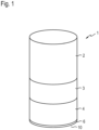
- Fig. 1 shows an overall view of a sealing element 1 with a ring-shaped sealing contour.
- An adapter 3 is attached to a housing 2 containing power and control electronics, which in turn carries an insulating body 4.
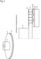
- a circular carrier substrate 6 of a heating element is arranged on the underside of the insulating body.
- the carrier substrate 6 is attached to a fastening body 5, which in turn is held in the insulation body 4.
- the carrier substrate 6 has on its front side (in the Drawing the underside of the carrier substrate) conductor tracks 7, which can be designed as heating conductors 7A or sensor conductors 7B, wherein several conductor tracks 7 are arranged next to one another at the same distance from the carrier substrate 6 and the conductor tracks 7 are arranged in two levels, i.e. at two different distances from the carrier substrate 6.
- All conductor tracks 7 are plated through the carrier substrate 6 by VIAs 13 so that they can be electrically contacted from the back of the carrier substrate 6.
- a cover layer 8 is arranged above the conductor tracks 7, on which a ring-shaped contour element 10 is attached by means of a connecting layer 9.
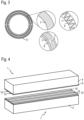
- Fig. 3 shows an example of how the conductor tracks 7 can be configured. It is evident that the conductor tracks 7 can be arranged side by side with the same distance from the carrier substrate 6, or they can be arranged one above the other with different distances from the carrier substrate 6, and can also overlap one another.
- Fig. 4 shows an overall view of a pair of sealing elements 1 with a strip-shaped sealing contour.
- Each insulating body 4 carries a heating element comprising a carrier substrate 6 with contour elements 10 and conductor tracks 7 arranged thereon, and the front sides of the two heating elements face each other.
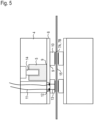
- Fig. 5 It can be seen that the carrier substrate 6 is connected with its rear side by a screw connection 14 to a fastening body 5, which in turn is fastened in the insulation body 4.
- strip-shaped contour elements 10 are applied directly to the carrier substrate 6, and a conductor track 7, which is designed here as a heating conductor 7A, is arranged on each contour element 10.
- the heating conductors 7A are therefore contacted by means of vias 13 both through the respective contour element 10 and through the carrier substrate 6.
- the vias are connected to connecting cables 11 at contact points 12 by soldering.
- the two sealing members 1 face each other in such a way that material 15 to be welded can be guided between them, wherein the two sealing members 1 are moved towards each other to weld the material 15 until they enclose the material 15 to be welded between them.
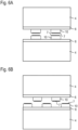
- FIG. 6A and 6B Two variants of a pairing of sealing elements 1 are shown, in which the relative arrangement of the contour elements 10 and conductor tracks 7 is different: While in the embodiment of the Fig. 6A a conductor track 7 of each of the two sealing elements 1 is arranged at the same location, so that the opposite conductor tracks 7 press against each other, in the embodiment of the Fig. 6B the conductor tracks 7 are arranged offset from one another in such a way that the conductor tracks 7 of one sealing element 1 press between two conductor tracks 7 of the other sealing element.
Landscapes
- Engineering & Computer Science (AREA)
- Mechanical Engineering (AREA)
- Physics & Mathematics (AREA)
- Thermal Sciences (AREA)
- Package Closures (AREA)
- Resistance Heating (AREA)
- Adhesives Or Adhesive Processes (AREA)
- Surface Heating Bodies (AREA)
Description
- Die Erfindung betrifft ein Siegelorgan zum Siegeln, d.h. zum stoffschlüssigen Verbinden, von Kunststoffen, vorrangig für die Herstellung von Verpackungen aus thermoplastischen Materialien wie Kunststofffolien oder Folienverbunde wie beispielsweise mit metallischen und nichtmetallischen Werkstoffen beschichtete Kunststofffolien, mit thermoplastischem Kunststoff beschichteten Metallfolien wie Aluminiumfolie und dergleichen, beispielsweise bei der Herstellung von Schlauchbeuteln, dem Verschließen von Behältern, beispielsweise durch das Aufsiegeln von Kunststofffolie mit oder ohne Aluminiumbeschichtung, kunststoffbeschichteter Aluminiumfolie oder andere thermisch schweißbare Materialien auf Behälter aus Kunststoff mit oder ohne Beschichtung oder aus Aluminium mit Kunststoffbeschichtung, oder die Versiegelung/Verschweißung von Folien oder Folienverbunden der oben genannten Art.
- Beim Siegeln kommen üblicherweise dauerbeheizte Siegelwerkzeuge zum Einsatz. Diese bestehen in der Regel aus einer Heizpatrone (gewickelter Widerstandsleiter) und einem Grundkörper, in dem die Heizpatrone sowie ein für die Temperaturregelung erforderlicher Temperaturfühler integriert sind. Dieser meist metallische Grundkörper (Siegelbalken, Siegelkopf oder Siegelwerkzeug genannt) weist zudem in der Regel eine Kontur auf, die der zu siegelnden Kontur entspricht. Diese kann als schmaler Steg oder auch als komplexe 3-dimensionale Oberflächenstruktur (z.B. Riffelprofilierung oder Pyramidenstümpfe, etc.) ausgebildet sein. Da prinzipbedingt der Ort der Wärmeerzeugung (Heizpatrone) und der Wirkstelle (Siegelkontur) sowie der Ort der Temperaturmessung in der Regel einige Millimeter voneinander getrennt sind und die Einzelkomponenten (Heizpatrone und Temperaturfühler) ein Verzögerungsverhalten (PT1 mit Zeitkonstante von teils einigen Sekunden) aufweisen, können im getakteten Dauerbetrieb größere Temperaturschwankungen infolge der thermischen Trägheit des Gesamtsystems auftreten, die sich negativ auf die Qualität der Siegelung auswirken. Dies tritt insbesondere dann ein, wenn ein Start-Stopp-Betrieb vorherrscht und dieses veränderliche Last-bzw. Systemverhalten nicht oder unzureichend durch die Temperaturregelung kompensiert werden kann. Die große thermische Masse des gesamten Aufbaus (insbesondere des metallischen Grundkörpers) macht weiterhin einen komplexen Aufbau zur thermischen Entkopplung erforderlich, woraus größere Baugruppen resultieren. Weiterhin führt die Erwärmung der metallischen Bauteile in Verbindung mit dem vergleichsweise großen Wärmeausdehnungskoeffizienten zu einer deutlichen Längen- bzw. Umfangszunahme was zu Planparallelitätsabweichungen der Werkzeuge führt oder entsprechend große Abstände zu relativ dazu bewegten Bauteilen (beispielsweise möglichst dicht geführten Stanzmessern zur Materialeinsparung) erforderlich macht.
- Es existieren Heizpatronen mit integrierten Temperatursensoren, diese lösen das geschilderte Problem allerdings nur unzureichend, da nicht wie erforderlich unmittelbar an der Wirkstelle oder möglichst nahe an der Wirkstelle, sondern mit einigem Abstand gemessen wird. Zudem führen die großen thermischen Massen der Siegelorgane zu trägem Regelverhalten. Weiterhin existieren Dickschichtheizer auf Metallbasis. Diese ermöglichen durch dünne aufgedruckte keramische Heiz- und Sensor-Leiterbahnen eine wirkstellennahe Temperaturmessung und Wärmeerzeugung, sind jedoch nur als ebene Siegelwerkzeuge herstellbar.
- Weitere Nachteile dieser bekannten Heizer bestehen darin, dass die Leiterbahnen an der Vorderseite des Heizers kontaktiert werden müssen und dass weder die Einstellung eines Temperaturprofils noch eine ortsabhängig variable Ansteuerung möglich ist.
-
US 4 292 118 A beschreibt eine Vorrichtung zur Erzeugung und Versiegelung mit Impulswärme, die einen vorzugsweise metallischen Wärmesenkenblock mit einer im wesentlichen glatten Oberfläche enthält, in der sich eine flache Nut befindet. Eine Auskleidung aus einem elektrischen Isolator / Wärmeleiterfilm ist in der flachen Rille vorgesehen und haftet an dieser als Beschichtung, und ein vorzugsweise metallisches Füllmaterial ist in der flachen Rille über der Auskleidung angeordnet, um eine glatte und vorzugsweise koplanare Oberfläche zu bilden. -
WO 2010/116567 A1 beschreibt ein Heißsiegelgerät, umfassend einen Pressmechanismus; ein Heizkörper, der an einer Backe von dem Pressmechanismus befestigt ist; und eine elektrische Leistungsschaltung, die mit dem Heizkörper verbunden ist, wobei die elektrische Leistungsschaltung elektrische Leistung von einer externen Energieversorgung empfängt, wobei das Heißsiegelgerät ein aus einem thermoplastischen Harz gemachtes Objekt unter Verwendung des Pressmechanismus klemmt und presst, den Heizkörper durch Hindurchleiten eines hohen elektrischen Stroms durch den Heizkörper in einer kurzen Zeit sofort erhitzt, das Objekt aufschmilzt und das Objekt durch Unterbrechen des elektrischen Stromes kühlt und erhärtet, wobei der Heizkörper umfasst: (a) eine dünne thermoelektrische Isolierplatte, die eine angemessene Größe und Dicke hat und die auf einer Hitzeableitungsbasis oder auf der Backe, die auch als die Hitzeableitungsbasis fungiert, überlagert ist, wobei die Hitzeableitungsbasis aus einem Metall gemacht ist und auf der Backe von dem Pressmechanismus angeordnet ist, (b) ein oder mehrere Heizkörperdrähte, von denen jeder eine dünne Metallwiderstandsplatte ist, die auf der dünnen thermoelektrischen Isolierplatte überlagert ist, wobei jeder Heizkörperdraht eine Elektrode, die mit der elektrischen Leistungsschaltung verbunden ist, und einen Hitzeerzeugungsabschnitt mit einer streifenartigen Form oder einer gewünschten Form umfasst, (c) einen thermisch leitenden elektrischen Isolator, der eine Keramikplatte ist, die auf dem Hitzeerzeugungsabschnitt überlagert ist, wobei der thermisch leitende elektrische Isolator eine flache Oberfläche hat, die den Hitzeerzeugungsabschnitt eng kontaktiert, wobei der thermisch leitende elektrische Isolator ein elektrischer Isolator ist und eine thermische Leitfähigkeit hat, die gleich oder höher als die von Tonerde ist, (d) ein thermoelektrischer Isolator, der exponierte Abschnitte von den Heizkörperdrähten und der Elektrode abdeckt, wobei der thermoelektrische Isolator einen Teil von den exponierten Abschnitten umgibt, die um den thermisch leitenden elektrischen Isolator herum angeordnet sind, so dass der Teil elektrisch und thermisch isoliert ist, und einen verbleibenden Teil von den exponierten Abschnitten umgibt, so dass der verbleibende Teil wenigstens elektrisch isoliert ist, und (e) eine dünne Trennfolie, die ständig oder nach Bedarf auf dem thermisch leitenden elektrischen Isolator mit oder ohne einen Spalt dazwischen überlagert ist, und (f) wobei die Elemente von dem in (a) bis (e) beschriebenen Heizkörper dazu gemacht sind, um einander eng zu kontaktieren, und an notwendigen Positionen unter Verwendung eines Klebstoffs, eines klebrigen Mittels oder eines physikalischen Verfahrens fixiert sind. -
DE 43 33 852 A1 beschreibt ein Heizelement für Folienschweißgeräte mit einer Dickschichtleiterbahn als Heizleiter auf einem Keramikgrundkörper, bei dem die Dickschichtleiterbahn in ihrer Längsrichtung hinsichtlich ihrer Breite und/oder Dicke variiert ist. -
US 5 682 732 A beschreibt eine Vorrichtung zum Verschweißen und/oder Verbinden von thermoplastischem Material oder mit Thermoplasten beschichteten Materialien, vorzugsweise Verpackungsmaterialien, durch Erhitzen und Pressen der Materialien im Schweißbereich, mit der Absicht, eine Oberflächenverschmelzung von aneinander anliegenden thermoplastischen Schichten zu erreichen, um eine dichte und mechanisch dauerhafte Verschweißung zu erhalten, wobei die Vorrichtung zwei Schweißbacken umfasst, die zueinander bewegbar angeordnet sind und so ausgerichtet sind, dass sie zwischen sich das zu verschweißende Material aufnehmen können, wobei mindestens die eine Schweißbacke einen Keramikteil aufweist, der mindestens ein Keramikmaterial umfasst, das elektrisch isolierend ist, wobei der Keramikteil im weiteren ein elektrisch leitendes Keramikmaterial umfasst, das einen oder mehrere im isolierenden Material eingebettete kontinuierliche Stränge formt, wobei der Strang oder die Stränge bei oder in der Nähe von seinen bzw. ihren Endpunkten mit einer elektrischen Stromquelle verbindbar ist bzw. sind und entlang seiner bzw. ihrer Länge eine variierende Breite, Tiefe und/oder Querschnittsfläche aufweist bzw. aufweisen. -
US 2008/314888 A1 beschreibt einen Dichtungsmechanismus, umfassend eine Wärmeisolationsbasis, einen Heizabschnitt und eine Druckfeder, wobei die Wärmeisolationsbasis einen linken Seitenteil, einen Mittelteil und einen rechten Seitenteil aufweist. Der Heizabschnitt enthält mindestens zwei Heizdrähte, die in einem bestimmten Abstand voneinander gleich beabstandet sind, eine linke Niete und eine rechte Niete, wobei die Heizdrähte an beiden Enden elektrisch mit der linken Niete und der rechten Niete verbunden sind. Die linke Niete und die rechte Niete des Heizabschnitts stehen mit der Rückseite der Wärmeisolationsbasis in Eingriff, so dass die Heizdrähte am mittleren Teil der Wärmeisolationsbasis positioniert sind und von der Rückseite der Wärmeisolationsbasis her durch die Wärmeisolationsbasis hindurch elektrisch kontaktiert sind. - Einige Aspekte der vorliegenden Erfindung betreffen ein Siegelorgan, bei dem wärmeerzeugende Elemente eines Heizelements von dessen Rückseite her kontaktiert sind. Weitere Aspekte betreffen ein Siegelorgan, bei dem der Ort der Wärmeerzeugung und der Ort der Wärmeabfuhr (d.h. die Wirkstelle) möglichst nah beieinander angeordnet sind. Weitere Aspekte betreffen ein Siegelorgan mit einem Heizelement, das einen integrierten Temperatursensor aufweist. Weitere Aspekte betreffen ein Siegelorgan mit einer definierten Siegelkontur. Weitere Aspekte betreffen ein Siegelorgan mit einer dreidimensional strukturierten Kontaktfläche. Weitere Aspekte betreffen ein Siegelorgan mit einem kreisrunden, ringförmigen oder streifenförmigen Heizelement. Weitere Aspekte betreffen ein Siegelorgan mit integrierten Elektronikschaltungen. Weitere Aspekte betreffen ein Siegelorgan mit der Möglichkeit, das Heizelement und/oder das zu verschweißende Material bedarfsweise zu kühlen. Weitere Aspekte betreffen ein Siegelorgan mit der Möglichkeit, das zu schweißende Material anzusaugen.
- Es hat sich gezeigt, dass die hier vorgeschlagenen Lösungen zu jedem Aspekt der Erfindung vorteilhaft sowohl jeweils einzeln als auch in beliebiger Kombination miteinander zur Verbesserung bekannter Siegelorgane beitragen können, und jede Kombination eines oder mehrerer der nachfolgend beschriebenen Merkmale mit denen bekannter Siegelorgane soll daher als vom Erfindungsgedanken umfasst angesehen werden.
- Die Erfindung geht von einem Siegelorgan zum thermischen Verbinden thermoplastischer Materialien aus, das ein Heizelement umfasst, welches ein flächiges Trägersubstrat mit einer Vorderseite und einer Rückseite aufweist, das aus einem elektrisch nichtleitenden keramischen Werkstoff besteht, und auf dessen Vorderseite mindestens zwei Heizleiter angeordnet sind.
- Erfindungsgemäß ist bei dem vorgeschlagenen Siegelorgan vorgesehen, dass die Heizleiter von der Rückseite des Trägersubstrats her durch das Trägersubstrat hindurch über senkrechte Durchkontaktierungen elektrisch kontaktiert sind, wobei mindestens zwei Heizleiter unabhängig voneinander ansteuerbar sind.
- Unter einem flächigen Trägersubstrat soll dabei ein plattenförmiges Element verstanden werden, d.h. ein Element, dessen Dickenabmessung klein ist gegenüber den Abmessungen in den beiden anderen Raumrichtungen, wobei es unerheblich ist, ob das Trägersubstrat insgesamt eben oder gebogen oder gewölbt ist. Allerdings besteht einer der Vorzüge des vorgeschlagenen Siegelorgans gerade darin, dass das keramische Trägersubstrat nicht nur eben, sondern auch gebogen oder gewölbt ausgeführt sein kann.
- Das Trägersubstrat kann beispielsweise die Form eines Quadrats oder anderen Polygons, eines Streifens, d.h. schmalen Rechtecks, kreis- oder ellipsenförmige Scheibe oder als Ring, der ebenfalls die äußere Form eines Polygons, Kreises usw. aufweisen kann, ausgeführt sein. Dadurch ist es möglich, ein Siegelorgan mit einem Heizelement bereitzustellen, mit dem unterschiedlichste Siegelanwendungen und Nahtformen realisiert werden können.
- Die Vorderseite des Trägersubstrats weist einen oder mehrere darauf angeordnete Heizleiter auf, die beispielsweise in einer Ebene (nebeneinander) oder in mehreren Ebenen (übereinander) angeordnet sein können, d.h. die Vorderseite des Heizelements ist dem zu siegelnden Material zugewandt.
- Zur Kontaktierung des oder der auf der Vorderseite des Trägersubstrats angeordneten Heizleiter von der Rückseite des Trägersubstrats her weist das Trägersubstrat sogenannte VIAs (Vertical Interconnect Access, Bezeichnung für senkrechte Durchkontaktierungen zwischen den Schichten einer integrierten Schaltung oder einer Leiterplatte), also elektrische Leiterzüge, die sich zwischen einer Vorderseite und einer Rückseite des Trägersubstrats in der Dickenrichtung des Trägersubstrats durch das Trägersubstrat hindurch erstrecken, auf. Beispielsweise kann das Trägersubstrat hierzu kleine Löcher in der Form von Durchgangsbohrungen aufweisen, deren Begrenzungsfläche mit elektrisch leitendem Material beschichtet sind oder die von elektrisch leitendem Material ausgefüllt sind.
- Das elektrisch leitende Material kann dabei beispielsweise eine druckbare elektrisch leitende Paste, beispielsweise eine mit elektrisch leitenden Partikeln versetzte Keramikmasse (Schlicker) sein. Zur elektrischen Kontaktierung eines Heizleiters kann beispielsweise das auf der Rückseite des Trägersubstrats liegende Ende des VIAs direkt kontaktiert sein, beispielsweise durch Federkontakte, Anlöten, Anschweißen oder Anschrauben usw.
- Mindestens zwei Heizleiter sind unabhängig voneinander ansteuerbar. Hierdurch kann je nach der Anordnung der zwei oder mehr Heizleiter zueinander bewirkt werden, dass das Heizelement über seine Vorderseite gesehen ein einstellbares Temperaturfeld erzeugt oder einen Ausgleich von unterschiedlich starker Wärmeabfuhr durch Einstellung eines sehr gleichmäßigen Temperaturprofiles über eine größere Fläche ermöglicht, dass die Heizleistung wählbar größer oder kleiner ist, usw.
- Gemäß einer Ausgestaltung ist bei dem vorgeschlagenen Siegelorgan vorgesehen, dass auf der Vorderseite des Trägersubstrats mindestens ein Sensorleiter zur Temperaturmessung angeordnet ist. Durch die so erreichte unmittelbare Nähe eines Sensorleiters zu einem Heizleiter wird der Sensorleiter fast identisch zum Heizleiter erwärmt. Aus der temperaturabhängigen Änderung des elektrischen Widerstands des Sensorleiters lässt sich damit auf einfache Weise die Temperatur des Heizelements ermitteln. Dieser Temperaturwert kann bequem zur Steuerung oder Regelung des Heizelements verwenden.
- Gemäß einer anderen Ausgestaltung ist bei dem vorgeschlagenen Siegelorgan vorgesehen, dass mindestens ein Heizleiter gleichzeitig als Sensorleiter dient, indem der sich mit der Temperatur ändernde elektrische Widerstand des Heizleiters selbst zur Ermittlung der Temperatur des Heizelements dient. Auch hier kann der so ermittelte Temperaturwert zur Steuerung oder Regelung des Heizelements verwendet werden.
- Die Verwendung der Leiterbahnen, d.h. des Heizleiters selbst oder eines dedizierten Sensorleiters, hat den weiteren Vorteil, dass die Widerstandsänderung bei Temperaturänderung aufgrund der geringen Schichtdicke von beispielsweise 5 bis 20µm und der daraus resultierenden geringen thermischen Masse sehr schnell erfolgt und dadurch eine schnelle Reaktion der Regelung ermöglicht wird, die sehr kleine Regelabweichungen ermöglicht.
- Der mindestens eine Heizleiter sowie, falls vorhanden, der mindestens eine Sensorleiter können vorteilhaft durch eine Dickschicht-Drucktechnologie hergestellt sein, die kostengünstig ist und es auch ermöglicht, Heizleiter und Sensorleiter entweder in einem Arbeitsschritt oder jedenfalls in Arbeitsschritten ein und desselben Verfahrens herzustellen. Besonders vorteilhaft können der oder die Heizleiter sowie, falls vorhanden, der oder die Sensorleiter aus einem elektrisch leitenden keramischen Werkstoff bestehen. Hierzu kann in einem Druckverfahren ein elektrisch leitender Keramikschlicker in Form von Leiterbahnen auf ein elektrisch nichtleitendes flächiges Keramiksubstrat, das zu diesem Zeitpunkt beispielsweise als Grünling, aber auch als gebrannte Keramik vorliegen kann, gedruckt werden. Dabei kann gleichzeitig die Durchkontaktierung des oder der der Heizleiter oder/und des oder der Sensorleiter erfolgen, indem beim Drucken der Schlicker auch in Löcher oder Bohrungen des Trägersubstrats injiziert wird, so dass VIAs geschaffen werden, die der elektrischen Kontaktierung der Heizleiter oder/und der Sensorleiter von der Rückseite des Trägersubstrats her dienen können. Nach einem anschließenden Trocknungsschritt kann dann das mit keramischen Leiterbahnen bedruckte Keramiksubstrat wie gewöhnlich gebrannt werden.
- Weiterhin kann vorgesehen sein, dass das Trägersubstrat mindestens eine Luftströmungsöffnung zum Ausstoßen oder Ansaugen von Luft aufweist. Beispielsweise können Luftströmungsöffnungen vorgesehen sein, durch die Kühlluft von der Rückseite des Heizelements zur Vorderseite des Heizelements geleitet wird, um das Heizelement sowie gegebenenfalls das verschweißte Material nach einem erfolgten Siegelvorgang schnell abzukühlen. Weiter beispielsweise können Luftströmungsöffnungen vorgesehen sein, durch die Umgebungsluft von der Vorderseite des Heizelements zur Rückseite des Heizelements geleitet wird, um das zu verschweißende Material, also beispielsweise eine Kunststofffolie, an das Heizelement zu saugen, um den thermischen Kontakt zwischen dem Siegelorgan und dem zu verschweißenden Material zu erhöhen und so das Resultat des Schweißvorgangs zu verbessern.
- Gemäß einer weiteren Ausgestaltung ist vorgesehen, dass die Vorderseite des Heizelements dreidimensional erhabene Strukturen aufweist. Dadurch ist es möglich, einerseits die Wärmeeinwirkung des Siegelorgans auf das zu verschweißende Material zu intensivieren, um eine innige Verbindung zu bewirken, und andererseits, strukturierte Schweißnähte zu schaffen.
- Hierfür kann beispielsweise vorgesehen sein, dass der mindestens eine Heizleiter oder/und der mindestens eine Sensorleiter eine dreidimensional erhabene Struktur bildet. Werden diese Leiterbahnen in einem Dickschicht-Druckverfahren, zur Erzielung einer größeren Dicke der Leiterbahnen gegebenenfalls in mehreren aufeinanderfolgenden Druckschritten, hergestellt, so sind die entstehenden Leiterbahnen gegenüber der Oberfläche des Trägersubstrats merklich erhaben und können daher direkt als dreidimensional erhabene Strukturen im obigen Sinne wirken.
- Alternativ oder zusätzlich kann vorgesehen sein, dass auf dem Trägersubstrat oder/und auf dem mindestens einen Heizleiter oder/und auf dem mindestens einen Sensorleiter ein flächiges Konturelement angeordnet ist, das eine dreidimensional erhabene Struktur bildet. Ein solches Konturelement kann beispielsweise entweder einstückig mit dem Trägersubstrat ausgebildet sein, oder selbst in einem Dickschicht-Druckverfahren hergestellt werden, indem eine Schicht aus gut wärmeleitendem Schlicker entweder direkt auf das Trägersubstrat oder über die Leiterbahnen gedruckt wird. Ein solches Konturelement kann aber beispielsweise auch, ähnlich wie das Trägersubstrat, vorgefertigt sein und nach dem Drucken und Trocknen der Leiterbahnen beispielsweise als Grünling oder als bereits gebrannte Keramik entweder mittels einer auf der Vorderseite des Trägersubstrats und den darauf angeordneten Leiterbahnen aufgebrachten Schicht aus Schlicker auf die Vorderseite des Trägerelements aufgeklebt werden oder auf die Vorderseite des Trägersubstrats und die darauf angeordneten Leiterbahnen beispielsweise mit einem Glaslot aufgelötet werden. Bei der letztgenannten Variante ist es besonders einfach, ein Konturelement bereitzustellen, das seinerseits an der Vorderseite dreidimensional strukturiert ist. Daran anschließend kann das neben dem Trägersubstrat und der oder den keramischen Leiterbahnen ein Konturelement umfassende Heizelement wie gewöhnlich gebrannt werden. Bei Ausgestaltungen, bei denen das Konturelement gleichzeitig das Element ist, das in direkten Kontakt mit dem zu verschweißenden Material tritt, und bei denen der oder die Heizleiter unter dem Konturelement angeordnet oder in dieses eingebettet sind, sollte das Material des Konturelements elektrisch nichtleitend sein, um Kurzschlüsse zu vermeiden.
- Weiterhin kann vorgesehen sein, dass das Konturelement mindestens eine Luftströmungsöffnung zum Ausstoßen oder Ansaugen von Luft aufweist. Die Position derartiger Luftströmungsöffnungen sollte dabei zweckmäßig so gewählt sein, dass sie bei der Erzeugung oder/und Anbringung des Konturelements über entsprechenden Luftströmungsöffnungen des Trägersubstrats zu liegen kommen, um die Durchleitung von Luft von der Rückseite zur Vorderseite oder von der Vorderseite zur Rückseite des Heizelements zu ermöglichen. Wie oben bereits beschrieben wird es dadurch ermöglicht, das Heizelement und gegebenenfalls das verschweißte Material schnell abzukühlen bzw. das zu verschweißende Material anzusaugen.
- Alternativ oder zusätzlich kann vorgesehen sein, dass das Konturelement mindestens eine oberflächliche Vertiefung zum Ableiten von Luft aufweist. Werden das Trägersubstrat und das Konturelement mit übereinander liegenden Luftströmungsöffnungen versehen, so können die Vertiefungen beispielsweise zur Ableitung von Kühlluft dienen, die von der Rückseite des Heizelements her an der Vorderseite des Heizelements ausgelassen wird. Beispielsweise kann ein ringförmiges Heizelement zum Aufsiegeln von Deckelfolie auf einen Verpackungsbecher an seiner Vorderseite radial verlaufende Nuten aufweisen, durch die Kühlluft abgeleitet wird. Es ist jedoch auch möglich, das Trägersubstrat an Stellen, die nicht von dem Konturelement bedeckt sind, mit Luftströmungsöffnungen zu versehen. Am obigen Beispiel erläutert könnte das Trägersubstrat kreisförmig und das Konturelement ringförmig sein. Weist dann das Trägersubstrat in einem zentralen, nicht vom Konturelement überdeckten Bereich Luftströmungsöffnungen auf, so kann die dadurch an der Vorderseite des Heizelements austretende Kühlluft durch die vorderseitig angebrachten Nuten des Konturelements nach außen abgeführt werden, wobei die erwärmten Bereiche des Heizelements, d.h. die Leiterbahnen und das Konturelement selbst, durch die vorbeiströmende Kühlluft gekühlt werden.
- Bevorzugt besteht das Konturelement aus einem elektrisch nichtleitenden keramischen Werkstoff mit guter Wärmeleitfähigkeit. Dadurch wird ein Kurzschluss zwischen den darunter liegenden Leiterbahnen vermieden, wobei die von dem oder den Heizleitern erzeugte Wärme sich jedoch gleichmäßig im Konturelement verteilt.
- Weiter vorteilhaft kann vorgesehen sein, dass das Heizelement an seiner Rückseite durch Federkontakte elektrisch kontaktiert ist. Auf diese Weise kann ein Heizelement an einem Siegelorgan einfacher und schneller ausgetauscht werden, als dies bei einer permanenten elektrischen Kontaktierung, beispielsweise durch angelötete Leitungen, der Fall wäre. Dennoch sind vom Erfindungsgedanken natürlich auch Ausgestaltungen umfasst, bei denen die elektrische Kontaktierung des Heizelements auf andere Weise, beispielsweise durch Steckkontakte, Löten oder Schweißen, beispielsweise Drahtbonden, realisiert ist.
- Zur Anbringung des vorgeschlagenen Heizelements an einem Siegelorgan kann weiterhin vorgesehen sein, dass das Heizelement mit seiner Rückseite an einem Befestigungskörper angebracht ist. Dabei kann die Verbindung zwischen Heizelement und Befestigungskörper vorteilhaft lösbar ausgeführt sein. Da das keramische Trägersubstrat sehr dünn gestaltet sein kann, erhält das Heizelement durch einen derartigen Befestigungskörper eine höhere Stabilität, wobei der Befestigungskörper gleichzeitig die elektrische Kontaktierung des Heizelements bereitstellen und die Anbringung des Heizelements an einem Siegelorgan ermöglichen kann, wobei die Verbindung zwischen Befestigungskörper und Siegelorgan vorteilhaft ebenfalls lösbar ausgeführt ist.
- In einer weiteren Ausgestaltung kann vorgesehen sein, dass der Befestigungskörper Bestandteil eines Gehäuses ist, das zur Anbringung an einer Verpackungsmaschine ausgebildet ist. In diesem Fall umfasst das Siegelorgan also neben dem Heizelement und dem Befestigungskörper, an dem das Heizelement angebracht ist, ein Gehäuse, an dem der Befestigungskörper angebracht ist. Das Gehäuse ist zur Anbringung an einer Verpackungsmaschine ausgebildet, so dass das Siegelorgan von der Verpackungsmaschine zumindest mit Strom, gegebenenfalls auch mit Kühlluft oder/und Unterdruck versorgt werden kann.
- Wenn das Siegelorgan, wie oben beschrieben, ein Gehäuse aufweist, so kann dieses vorteilhaft dazu genutzt werden, dass im Innern des Gehäuses eine Steuerungselektronik oder/und eine Leistungselektronik angeordnet ist. Dadurch ist das Siegelorgan autark einsetzbar, d.h. die Verpackungsmaschine selbst muss weder die Steuerung oder Regelung des Siegelorgans bewirken noch die benötigte Spannung bereitstellen, weil dies von dem Siegelorgan selbst bewerkstelligt wird. Über die Verpackungsmaschine muss nur noch die allgemeine Energieversorgung, beispielsweise mit einer Versorgungsspannung, gegebenenfalls Druckluft oder/und Unterdruck, und gegebenenfalls die Definition bestimmter, für den Siegelvorgang benötigter Sollgrößen wie beispielsweise die Solltemperatur und die Einwirkzeit des Siegelorgans auf das zu verschweißende Material, zur Verfügung gestellt werden. Das Gehäuse kann dabei für unterschiedlichste Siegelorgane jeweils gleichartig ausgeführt sein, so dass Verpackungsmaschinen, an denen diese Siegelorgane eingesetzt werden sollen, lediglich eine stets gleichartige Schnittstelle bereitstellen müssen, die zur Anbringung des Gehäuses des Siegelorgans ausgebildet ist.
- In verschiedenen Ausgestaltungen des vorgeschlagenen Siegelorgans kann vorgesehen sein, dass mindestens zwei Heizleiter mit gleichem Abstand zum Trägersubstrat angeordnet sind. Hierdurch können mehrere Heizleiter auf derselben Ebene dargestellt werden, die jeweils nur einen Teilabschnitt des Heizelements beheizen. Dadurch ist es möglich, über die Oberfläche, d.h. die Vorderseite des Heizelements ein Temperaturprofil einzustellen, indem verschiedene Heizleiter unterschiedlich angesteuert werden.
- Alternativ oder zusätzlich kann vorgesehen sein, dass mindestens zwei Heizleiter mit unterschiedlichem Abstand zum Trägersubstrat angeordnet sind. Beispielsweise kann zunächst ein erster Heizkreis auf das Trägersubstrat aufgebracht, beispielsweise gedruckt werden, anschließend eine Trennschicht über die Vorderseite des Trägersubstrats mit dem ersten Heizleiter aufgebracht, beispielsweise gedruckt werden und schließlich ein zweiter Heizleiter auf das Trägersubstrat aufgebracht, beispielsweise gedruckt werden. Hierdurch ist es beispielsweise möglich, dass eine hohe Heizleistung erzielt wird, wobei der erste und der zweite Heizleiter einander auch kreuzen können, ohne dass ein Kurzschluss zwischen ihnen auftreten kann.
- In ähnlicher Weise kann vorgesehen sein, dass mindestens ein Heizleiter und ein Sensorleiter mit gleichem Abstand zum Trägersubstrat angeordnet sind, oder/und dass mindestens ein Heizleiter und ein Sensorleiter mit unterschiedlichem Abstand zum Trägersubstrat angeordnet sind.
- In einer weiteren Ausgestaltung kann bei dem vorgeschlagenen Siegelorgan vorgesehen sein, dass mindestens ein Heizleiter spulenförmig ausgebildet und mit einer Wechselspannung beaufschlagbar ist. Auf diese Weise entsteht ein induktives Wechselfeld, das bei metallhaltigem zu verschweißendem Material wie beispielsweise Aluminiumverbundfolie zu einer alleinigen oder zusätzlichen Erwärmung des zu verschweißenden Materials führt.
- Die Erfindung beschreibt verschiedene Ausführungen von Siegelorganen mit Heizelementen, bei denen dünne keramischen Heizleiter in Dickschichttechnik auf dünne Keramiksubstrate (beispielsweise mit einer Dicke von 1 mm oder weniger) aufgebracht sind. Diese durch gezielte Bahnführung zu Heizflächen gestaltbaren Heizbahnen besitzen selbst nur eine sehr geringe thermische Masse und eine sehr hohe Leistungsdichte (bis über 50 W/cm2), was eine sehr hohe Aufheizdynamik erlaubt. Weiterhin können ebenfalls sehr dynamische Temperaturfühler integriert werden, was eine sehr hohe Regelgenauigkeit ermöglicht. Die Heizer können als Platten, Streifen, Scheiben oder Ringe ausgeführt sein und somit an die Geometrie der zu siegelnden Fläche angepasst werden. Weiterhin können ein oder mehrere nebeneinander oder versetzt zueinander segmentweise angeordnete Heizkreise realisiert werden, um mit jeweils separater Regelung eine definierte Temperaturverteilung an der Wirkstelle zu erzeugen. Die Heizleiterbahnen können zudem in mehreren Ebenen angeordnet sein oder/und spulenartig ausgeführt sein, so dass bei Anlegen einer Wechselspannung ein Magnetfeld entsteht, das den Siegelvorgang von aluminiumhaltigen Folien verbessert.
- Eine weitere Besonderheit der Erfindung stellt die mögliche Anbindung des flachen Heizelements (Scheibe, Ring oder Streifen) im Bereich der Wirkstelle an die Siegelfläche/Wirkstelle durch ein weiteres dünnes (beispielsweise ca. 1 mm dickes) keramisches oder metallisches Bauteil, nämlich ein die Siegelkontur aufweisendes Konturelement, mit hoher Wärmeleitfähigkeit dar. Geeignete Materialien hierfür sind beispielsweise Aluminiumnitrid (AlN) oder Siliciumcarbid (SiSiC oder SSiC). Über dieses sind der unmittelbare Wärmeeintrag sowie die Ausbildung der erforderlichen (3-dimensionalen) Siegelkontur möglich. Dieses Konturelement kann erfindungsgemäß mittels Kleben, Löten oder Ansintern mit der Oberfläche des Dickschichtheizers stoffschlüssig verbunden werden.
- Des Weiteren kann das Heizelement auf einen thermisch isolierenden Grundträger (aus Keramik oder hochtemperaturbeständigen Kunststoff) durch Kleben oder eine kraftschlüssige Verbindung (Klemmen, Schrauben) angebracht werden. Dies wirkt sich besonders positiv hinsichtlich geforderter thermischer Entkopplung zur dahinterliegenden mechanischen Anbindung des Siegelelements aus. Dazu können Befestigungselemente an das Heizelement stoffschlüssig angebracht werden, die eine Verschraubung oder Klemmung mit dem Grundträger und somit Austausch im Falle eines Defektes ermöglichen. Die Heizelemente selbst verfügen über eine Durchkontaktierung zur Rückseite des Heizersubstrats, an der die elektrische Kontaktierung mittels Federkontakten, Anlöten, Anschweißen, Anschrauben oder mechanischen Andrücken realisiert werden kann.
- Eine weitere vorteilhafte Ausführungsform stellt die unmittelbare Integration von Regel- und Steuerelementen zu einem autark funktionierenden Siegelmodul dar. Dieses muss lediglich mit Energie versorgt und die Sollparameter vorgegeben werden. Diese Variante wirkt sich besonders positiv hinsichtlich einer kompakten Bauweise, einfachen Integration in eine Maschine und vereinfachten Wartung durch Austausch aus.
- Vorteile des vorgeschlagenen Siegelorgans bezogen auf die technischen Merkmale bestehen dabei insbesondere im Folgenden:
- Geringe thermische Masse und hohe Aufheizdynamik ermöglichen in Verbindung mit einem entsprechend dynamischen Regler eine sehr hohe Regelgenauigkeit mit einer Regelabweichung von wenigen Kelvin (auch im Fall schwankender Lasten).
- Kompakte Ausführung des Heizelements und Integration von Regel- und Steuerelementen im Siegelorgan selbst ermöglicht kompakte Baugruppe mit guter thermischer Charakteristik.
- Geringe thermische Ausdehnungskoeffizienten der verwendeten Keramikbauteile bedingen bessere Maßhaltigkeit über ein breites Temperaturspektrum.
- Durch die thermische Isolation können erforderliche Regelkomponenten (Elektronik) direkt in das Siegelorgan integriert werden, was insbesondere bei Verwendung mehrerer separater Heizkreise (z.B. segmentweise) vorteilhaft ist und die elektrische Anbindung an die Maschine erleichtert.
- Durch die Verwendung mehrerer segmentweise nebeneinander oder übereinander angeordneter Heizkreise können Temperaturprofile bzw. Leistungsstufen dargestellt werden.
- Durch spulenartige Anordnung von Leiterschleifen, auch über mehrere Ebenen, wird bei Anlegen einer Wechselspannung ein Magnetfeld erzeugt, das in metallischen Komponenten in den Fügeteilen Wirbelströme erzeugt und dadurch zur alleinigen, oder gegenüber einer Wärmeleitung vom Heizelement zum zu verschweißenden Material hauptsächlichen, oder zusätzlichen inneren Erwärmung der Fügepartner führt.
- Nachfolgend wird die Erfindung anhand von Ausführungsbeispielen und zugehörigen Zeichnungen näher erläutert. Dabei zeigen:
-
Fig. 1 ein Ausführungsbeispiel eines Siegelorgans mit einem Heizelement mit ringförmiger Siegelkontur, -
Fig. 2 das Heizelement des Siegelorgans ausFig. 1 , -
Fig. 3 eine beispielhafte Konfiguration der Leiterbahnen des Heizelements ausFig. 2 , -
Fig. 4 ein Ausführungsbeispiel eines Siegelorgans mit einem Heizelement mit streifenförmiger Siegelkontur, -
Fig. 5 das Heizelement des Siegelorgans ausFig. 4 , und -
Fig. 6A und 6B beispielhafte Konfigurationen der Leiterbahnen des Heizelements ausFig. 5 . -
Fig. 1 zeigt eine Gesamtansicht eines Siegelorgans 1 mit einer ringförmigen Siegelkontur. An einem Gehäuse 2, das eine Leistungs- und Regelelektronik enthält, ist ein Adapter 3 angebracht, der seinerseits einen Isolationskörper 4 trägt. An der Unterseite des Isolationskörpers ist ein kreisförmiges Trägersubstrat 6 eines Heizelements angeordnet. Wie ausFig. 2 ersichtlich ist, ist das Trägersubstrat 6 an einem Befestigungskörper 5 angebracht, der seinerseits in dem Isolationskörper 4 gehalten ist. Das Trägersubstrat 6 weist an seiner Vorderseite (in der Zeichnung die Unterseite des Trägersubstrats) Leiterbahnen 7 auf, die als Heizleiter 7A oder Sensorleiter 7B ausgebildet sein können, wobei mehrere Leiterbahnen 7 nebeneinander mit dem gleichen Abstand zum Trägersubstrat 6 angeordnet sind und die Leiterbahnen 7 in zwei Ebenen, also mit zwei verschiedenen Abständen zum Trägersubstrat 6, angeordnet sind. - Alle Leiterbahnen 7 sind durch VIAs 13 durch das Trägersubstrat 6 durchkontaktiert, so dass sie von der Rückseite des Trägersubstrats 6 her elektrisch kontaktiert werden können.
- Über den Leiterbahnen 7 ist eine Abdeckschicht 8 angeordnet, auf der ein ringförmiges Konturelement 10 mittels einer Verbindungsschicht 9 befestigt ist.
-
Fig. 3 zeigt beispielhaft, wie die Leiterbahnen 7 konfiguriert sein können. Es ist ersichtlich, dass Leiterbahnen 7 sowohl mit gleichem Abstand zum Trägersubstrat 6 nebeneinander als auch mit unterschiedlichem Abstand zum Trägersubstrat 6 übereinander und dabei auch einander überlappend angeordnet sein können. -
Fig. 4 zeigt eine Gesamtansicht eines Paares von Siegelorganen 1 mit einer streifenförmigen Siegelkontur. Je ein Isolationskörper 4 trägt dabei ein Heizelement, das ein Trägersubstrat 6 mit darauf angeordneten Konturelementen 10 und Leiterbahnen 7 aufweist, und die Vorderseiten der beiden Heizelemente sind einander zugewandt. - Aus
Fig. 5 wird ersichtlich, dass das Trägersubstrat 6 mit seiner Rückseite durch eine Verschraubung 14 mit einem Befestigungskörper 5 verbunden ist, der seinerseits in dem Isolationskörper 4 befestigt ist. - Bei dieser Ausführungsform sind streifenförmige Konturelemente 10 direkt auf dem Trägersubstrat 6 angebracht, und auf jedem Konturelement 10 ist eine Leiterbahn 7 angeordnet, die hier als Heizleiter 7A ausgeführt ist. Die Heizleiter 7A sind daher mittels VIAs 13 sowohl durch das jeweilige Konturelement 10 als auch durch das Trägersubstrat 6 hindurchkontaktiert. An der Rückseite des Trägersubstrats 6 sind die VIAs an Kontaktstellen 12 durch Löten mit Anschlusskabeln 11 verbunden.
- Die zwei Siegelorgane 1 sind einander so zugewandt, dass zu verschweißendes Material 15 zwischen ihnen hindurch geführt werden kann, wobei die beiden Siegelorgane 1 zum Verschweißen des Materials 15 aufeinander zu bewegt werden, bis sie das zu verschweißende Material 15 zwischen sich einschließen.
- In den
Figuren 6A und 6B sind zwei Varianten einer Paarung von Siegelorganen 1 dargestellt, bei denen die relative Anordnung der Konturelemente 10 und Leiterbahnen 7 unterschiedlich ist:
Während bei der Ausführungsform derFig. 6A je eine Leiterbahn 7 beider Siegelorgane 1 an derselben Stelle angeordnet ist, so dass die gegenüberliegenden Leiterbahnen 7 gegeneinander drücken, sind bei der Ausführungsform derFig. 6B die Leiterbahnen 7 versetzt zueinander so angeordnet, dass die Leiterbahnen 7 des einen Siegelorgans 1 zwischen zwei Leiterbahnen 7 des anderen Siegelorgans drücken. -
- 1
- Siegelorgan
- 2
- Gehäuse
- 3
- Adapter
- 4
- Isolationskörper
- 5
- Befestigungskörper
- 6
- Trägersubstrat
- 7
- Leiterbahn
7A Heizleiter
7B Sensorleiter - 8
- Abdeckschicht
- 9
- Verbindungsschicht
- 10
- Konturelement
- 11
- Anschlusskabel
- 12
- Kontaktstelle
- 13
- VIA
- 14
- Verschraubung
- 15
- zu verschweißendes Material
Claims (15)
- Siegelorgan (1) zum thermischen Verbinden thermoplastischer Materialien (15), umfassend ein Heizelement, das ein flächiges Trägersubstrat (6) mit einer Vorderseite und einer Rückseite aufweist, das aus einem elektrisch nichtleitenden keramischen Werkstoff besteht, auf dessen Vorderseite mindestens zwei Heizleiter (7A) angeordnet und von der Rückseite des Trägersubstrats (6) her durch das Trägersubstrat (6) hindurch über senkrechte Durchkontaktierungen (13) elektrisch kontaktiert sind, wobei mindestens zwei Heizleiter (7A) unabhängig voneinander ansteuerbar sind.
- Siegelorgan nach Anspruch 1, bei dem auf der Vorderseite des Trägersubstrats (6) mindestens ein Sensorleiter (7B) zur Temperaturmessung angeordnet ist.
- Siegelorgan nach Anspruch 1 oder 2, bei dem mindestens ein Heizleiter (7A) oder/und mindestens ein Sensorleiter (7B) durch eine Dickschicht-Drucktechnologie hergestellt ist.
- Siegelorgan nach Anspruch 3, bei dem mindestens ein Heizleiter (7A) oder/und mindestens ein Sensorleiter (7B) aus einem elektrisch leitenden keramischen Werkstoff besteht.
- Siegelorgan nach einem der vorherigen Ansprüche, bei dem das Trägersubstrat (6) mindestens eine Luftströmungsöffnung zum Ausstoßen oder Ansaugen von Luft aufweist.
- Siegelorgan nach einem der vorherigen Ansprüche, bei dem die Vorderseite des Heizelements dreidimensional erhabene Strukturen aufweist.
- Siegelorgan nach Anspruch 6, bei dem mindestens ein Heizleiter (7A) oder/und mindestens ein Sensorleiter (7B) eine dreidimensional erhabene Struktur bildet.
- Siegelorgan nach Anspruch 6, bei dem auf dem Trägersubstrat (6) oder/und auf mindestens einem Heizleiter (7A) oder/und auf mindestens einem Sensorleiter (7B) ein flächiges Konturelement (10) angeordnet ist, das eine dreidimensional erhabene Struktur bildet.
- Siegelorgan nach Anspruch 8, bei dem das Konturelement (10) mindestens eine Luftströmungsöffnung zum Ausstoßen oder Ansaugen von Luft oder/und mindestens eine oberflächliche Vertiefung zum Ableiten von Luft aufweist oder/und aus einem keramischen Werkstoff mit guter Wärmeleitfähigkeit besteht.
- Siegelorgan nach einem der vorherigen Ansprüche, bei dem das Heizelement an seiner Rückseite durch Federkontakte, Steckkontakte, Löten oder Schweißen, beispielsweise Drahtbonden, elektrisch kontaktiert ist oder/und mit seiner Rückseite an einem Befestigungskörper (5) angebracht ist.
- Siegelorgan nach Anspruch 10, bei dem der Befestigungskörper (5) Bestandteil eines Gehäuses (2) ist, das zur Anbringung an einer Verpackungsmaschine ausgebildet ist.
- Siegelorgan nach Anspruch 11, bei dem im Innern des Gehäuses (2) eine Steuerungselektronik oder/und eine Leistungselektronik angeordnet ist.
- Siegelorgan nach einem der vorherigen Ansprüche, bei dem mindestens zwei Heizleiter (7A) mit gleichem Abstand zum Trägersubstrat (6) angeordnet sind oder mindestens zwei Heizleiter (7A) mit unterschiedlichem Abstand zum Trägersubstrat (6) angeordnet sind.
- Siegelorgan nach einem der vorherigen Ansprüche, bei dem mindestens ein Heizleiter (7A) und ein Sensorleiter (7B) mit gleichem Abstand zum Trägersubstrat (6) angeordnet sind oder mindestens ein Heizleiter (7A) und ein Sensorleiter (7B) mit unterschiedlichem Abstand zum Trägersubstrat (6) angeordnet sind.
- Siegelorgan nach einem der vorherigen Ansprüche, bei dem mindestens ein Heizleiter (7A) spulenförmig ausgebildet und mit einer Wechselspannung beaufschlagbar ist.
Priority Applications (2)
| Application Number | Priority Date | Filing Date | Title |
|---|---|---|---|
| EP24153338.9A EP4345018A3 (de) | 2016-09-21 | 2017-09-21 | Siegelorgan |
| EP20020306.5A EP3753715B1 (de) | 2016-09-21 | 2017-09-21 | Siegelorgan |
Applications Claiming Priority (2)
| Application Number | Priority Date | Filing Date | Title |
|---|---|---|---|
| DE102016117834.9A DE102016117834A1 (de) | 2016-09-21 | 2016-09-21 | Siegelorgan |
| PCT/EP2017/073903 WO2018055034A1 (de) | 2016-09-21 | 2017-09-21 | Siegelorgan |
Related Child Applications (4)
| Application Number | Title | Priority Date | Filing Date |
|---|---|---|---|
| EP24153338.9A Division EP4345018A3 (de) | 2016-09-21 | 2017-09-21 | Siegelorgan |
| EP24153338.9A Division-Into EP4345018A3 (de) | 2016-09-21 | 2017-09-21 | Siegelorgan |
| EP20020306.5A Division EP3753715B1 (de) | 2016-09-21 | 2017-09-21 | Siegelorgan |
| EP20020306.5A Division-Into EP3753715B1 (de) | 2016-09-21 | 2017-09-21 | Siegelorgan |
Publications (3)
| Publication Number | Publication Date |
|---|---|
| EP3515693A1 EP3515693A1 (de) | 2019-07-31 |
| EP3515693B1 EP3515693B1 (de) | 2020-07-01 |
| EP3515693B2 true EP3515693B2 (de) | 2025-06-25 |
Family
ID=60037560
Family Applications (3)
| Application Number | Title | Priority Date | Filing Date |
|---|---|---|---|
| EP24153338.9A Withdrawn EP4345018A3 (de) | 2016-09-21 | 2017-09-21 | Siegelorgan |
| EP20020306.5A Active EP3753715B1 (de) | 2016-09-21 | 2017-09-21 | Siegelorgan |
| EP17780653.6A Active EP3515693B2 (de) | 2016-09-21 | 2017-09-21 | Siegelorgan |
Family Applications Before (2)
| Application Number | Title | Priority Date | Filing Date |
|---|---|---|---|
| EP24153338.9A Withdrawn EP4345018A3 (de) | 2016-09-21 | 2017-09-21 | Siegelorgan |
| EP20020306.5A Active EP3753715B1 (de) | 2016-09-21 | 2017-09-21 | Siegelorgan |
Country Status (5)
| Country | Link |
|---|---|
| US (1) | US11667421B2 (de) |
| EP (3) | EP4345018A3 (de) |
| CN (1) | CN109715374A (de) |
| DE (1) | DE102016117834A1 (de) |
| WO (1) | WO2018055034A1 (de) |
Families Citing this family (11)
| Publication number | Priority date | Publication date | Assignee | Title |
|---|---|---|---|---|
| GB201810694D0 (en) * | 2018-06-29 | 2018-08-15 | Randox Laboratories Ltd | Cartridge sealing apparatus |
| DE102019202755A1 (de) * | 2019-02-28 | 2020-09-03 | Multivac Sepp Haggenmüller Se & Co. Kg | Verfahren zum Betreiben einer Verpackungsmaschine |
| GB2582166A (en) * | 2019-03-13 | 2020-09-16 | Green Light Packaging Ltd | Film-closure apparatus for plastic film material |
| US20240217187A1 (en) | 2020-07-01 | 2024-07-04 | Gea Food Solutions Germany Gmbh | Sealing Tool Having A Heating Means |
| US12240641B2 (en) * | 2020-09-09 | 2025-03-04 | watttron GmbH | Sealing method |
| EP4000874B1 (de) * | 2020-11-23 | 2023-10-04 | KOCH Pac-Systeme GmbH | Verfahren und vorrichtung zum herstellen und prüfen einer verpackung |
| HUE067568T2 (hu) | 2020-11-23 | 2024-10-28 | Koch Pac Systeme Gmbh | Eljárás csomagolás elõállítására |
| DE102021124794A1 (de) | 2021-09-24 | 2023-03-30 | Ampack Gmbh | Siegelungsvorrichtung, Siegelungsstation und Verfahren zu einem Betrieb einer Siegelungsvorrichtung |
| DE102021124797A1 (de) | 2021-09-24 | 2023-03-30 | Ampack Gmbh | Siegelungsvorrichtung, Siegelungsstation und Verfahren zur Herstellung einer solchen Siegelungsvorrichtung |
| WO2023078921A1 (de) * | 2021-11-05 | 2023-05-11 | Gea Food Solutions Germany Gmbh | Heizelement aus einem keramischen werkstoff |
| EP4426544A1 (de) * | 2021-11-05 | 2024-09-11 | Gea Food Solutions Germany GmbH | Siegelwerkzeug mit einer heizplatte mit gestapelten leiterbahnen |
Citations (6)
| Publication number | Priority date | Publication date | Assignee | Title |
|---|---|---|---|---|
| US5715656A (en) † | 1996-02-05 | 1998-02-10 | Triangle Package Machinery Corporation | Form, fill and seal machine |
| DE69416113T2 (de) † | 1993-03-02 | 1999-05-27 | Tetra Laval Holdings & Finance S.A., Pully | Schweissbacke gebildet aus zwei keramikmaterialien, wovon eines elektrisch leitend ist |
| EP1560751B1 (de) † | 2002-11-06 | 2006-10-18 | CFS Germany GmbH | Widerstandsheizung |
| WO2008034624A1 (de) † | 2006-09-22 | 2008-03-27 | Cfs Germany Gmbh | Heizplatte mit einer vielzahl von heizpatronen |
| WO2015000748A2 (de) † | 2013-07-03 | 2015-01-08 | Technische Universität Dresden | Vorrichtung zum beheizen von vorformkörpern oder flächigen oder vorgeformten halbzeugen aus thermoplastischem kunststoff |
| EP2293909B1 (de) † | 2008-05-29 | 2015-04-15 | Fraunhofer-Gesellschaft zur Förderung der angewandten Forschung | Verfahren und heizeinrichtung zum thermoformen |
Family Cites Families (16)
| Publication number | Priority date | Publication date | Assignee | Title |
|---|---|---|---|---|
| US3367261A (en) * | 1965-08-16 | 1968-02-06 | Kashiwagi Kimifumi | Apparatus for continuous heat-sealing of thermoplastic sheets |
| CA948977A (en) | 1972-06-12 | 1974-06-11 | Du Pont Of Canada Limited | Impulse sealer for sealing and separating liquid filled pouches |
| US4292118A (en) * | 1980-05-08 | 1981-09-29 | Ihor Wyslotsky | Impulse heat generation and sealer apparatus |
| DE4333852A1 (de) * | 1993-09-23 | 1995-03-30 | Lust Hybrid Technik Gmbh | Heizelement für Folienschweißgeräte |
| DE9409636U1 (de) | 1994-06-15 | 1994-09-15 | Inocermic Gesellschaft für innovative Keramik mbH, 07629 Hermsdorf | Heizspiegel für das Stumpfschweißen thermoplastischer Kunststoffteile |
| US9021771B2 (en) * | 2003-07-31 | 2015-05-05 | Sunbeam Products, Inc. | Heat sealer with algorithm for regulating sealing temperature |
| DE202005005126U1 (de) * | 2005-03-29 | 2006-08-10 | Wolf, Hans | Siegelgerät |
| US8592730B2 (en) | 2006-12-20 | 2013-11-26 | Tomier, Inc. | Heater assembly for suture welder |
| TW200900325A (en) * | 2007-06-23 | 2009-01-01 | ren-tang Zhang | Structural improvement of electric heating base of sealing machine |
| DE202008003136U1 (de) | 2008-03-05 | 2008-07-31 | Leister Process Technologies | Elektrischer Heizkeil |
| KR20120117983A (ko) | 2009-04-10 | 2012-10-25 | 아쯔노브 사까모또 | 임펄스 실러의 세라믹스로 커버된 히터 |
| CN202053520U (zh) | 2011-05-24 | 2011-11-30 | 涂泽兵 | 一种ppr热补器 |
| JP5335966B1 (ja) | 2012-05-23 | 2013-11-06 | トタニ技研工業株式会社 | プラスチックフィルムヒートシール装置 |
| DE102013223847A1 (de) * | 2013-11-21 | 2015-05-21 | Robert Bosch Gmbh | Trägersubstrat für einen thermoelektrischen Generator und elektrische Schaltung |
| DE102014201640A1 (de) * | 2014-01-30 | 2015-07-30 | BSH Hausgeräte GmbH | Temperaturmessung an einer Flächenheizung für ein Haushaltsgerät |
| CN104924599A (zh) | 2015-06-30 | 2015-09-23 | 柳州市劲新科技有限责任公司 | 缆索气囊加热装置 |
-
2016
- 2016-09-21 DE DE102016117834.9A patent/DE102016117834A1/de not_active Withdrawn
-
2017
- 2017-09-21 EP EP24153338.9A patent/EP4345018A3/de not_active Withdrawn
- 2017-09-21 EP EP20020306.5A patent/EP3753715B1/de active Active
- 2017-09-21 US US16/334,621 patent/US11667421B2/en active Active
- 2017-09-21 WO PCT/EP2017/073903 patent/WO2018055034A1/de not_active Ceased
- 2017-09-21 CN CN201780058112.4A patent/CN109715374A/zh active Pending
- 2017-09-21 EP EP17780653.6A patent/EP3515693B2/de active Active
Patent Citations (7)
| Publication number | Priority date | Publication date | Assignee | Title |
|---|---|---|---|---|
| DE69416113T2 (de) † | 1993-03-02 | 1999-05-27 | Tetra Laval Holdings & Finance S.A., Pully | Schweissbacke gebildet aus zwei keramikmaterialien, wovon eines elektrisch leitend ist |
| US5715656A (en) † | 1996-02-05 | 1998-02-10 | Triangle Package Machinery Corporation | Form, fill and seal machine |
| EP1560751B1 (de) † | 2002-11-06 | 2006-10-18 | CFS Germany GmbH | Widerstandsheizung |
| WO2008034624A1 (de) † | 2006-09-22 | 2008-03-27 | Cfs Germany Gmbh | Heizplatte mit einer vielzahl von heizpatronen |
| EP2293909B1 (de) † | 2008-05-29 | 2015-04-15 | Fraunhofer-Gesellschaft zur Förderung der angewandten Forschung | Verfahren und heizeinrichtung zum thermoformen |
| WO2015000748A2 (de) † | 2013-07-03 | 2015-01-08 | Technische Universität Dresden | Vorrichtung zum beheizen von vorformkörpern oder flächigen oder vorgeformten halbzeugen aus thermoplastischem kunststoff |
| DE102014202302A1 (de) † | 2013-07-03 | 2015-01-08 | Technische Universität Dresden | Vorrichtung zum Beheizen von Vorformkörpern |
Also Published As
| Publication number | Publication date |
|---|---|
| EP3515693B1 (de) | 2020-07-01 |
| US11667421B2 (en) | 2023-06-06 |
| EP3515693A1 (de) | 2019-07-31 |
| EP4345018A2 (de) | 2024-04-03 |
| CN109715374A (zh) | 2019-05-03 |
| EP3753715B1 (de) | 2024-01-24 |
| EP4345018A3 (de) | 2024-06-05 |
| EP3753715C0 (de) | 2024-01-24 |
| EP3753715A1 (de) | 2020-12-23 |
| US20210276755A1 (en) | 2021-09-09 |
| WO2018055034A1 (de) | 2018-03-29 |
| DE102016117834A1 (de) | 2018-03-22 |
Similar Documents
| Publication | Publication Date | Title |
|---|---|---|
| EP3515693B2 (de) | Siegelorgan | |
| DE69523409T2 (de) | Herstellung von Lötverbindungen zur Verwendung in der Verpackung von elektrischen Schaltungen | |
| EP2752084B1 (de) | Elektrische heizeinheit, heizvorrichtung für ein fahrzeug und verfahren zur herstellung einer heizeinheit | |
| DE112014001661T5 (de) | Strahlungsheizungsvorrichtung | |
| DE19737471C2 (de) | Heizeinrichtung | |
| WO2018108195A1 (de) | Thermoelektrische vorrichtung | |
| DE102016101945B4 (de) | Heißnietstempel und Heißnietvorrichtung | |
| EP1560751B1 (de) | Widerstandsheizung | |
| EP2106892A1 (de) | Heizplatte für Werkstücke | |
| EP3167480B1 (de) | Kühlvorrichtung, verfahren zur herstellung einer kühlvorrichtung und leistungsschaltung | |
| DE68908362T2 (de) | Abbrechbares selbstregulierendes Heizelement für die Oberflächenmontagetechnik. | |
| DE102022207567A1 (de) | Elektrische Vorrichtung, insbesondere Steuergerät | |
| DE102007050405A1 (de) | Elektrische Leistungskomponente, insbesondere Leistungshalbleiter-Modul, mit einer Kühlvorrichtung und Verfahren zum flächigen und wärmeleitenden Anbinden einer Kühlvorrichtung an eine elektrische | |
| CH689530A5 (de) | Bauteilkombination fuer elektrische Heizplatten, Zuendeinrichtungen oder Temperatursensoren. | |
| DE102016115221A1 (de) | Verfahren zum Verbinden von mindestens zwei Substraten zur Bildung eines Moduls | |
| WO2010083976A1 (de) | Vorrichtung zum auflöten eines leiters auf einen schaltungsträger | |
| WO2022053586A1 (de) | Siegelorgan | |
| EP1445553B1 (de) | Vorrichtung zum Austausch von Wärme | |
| WO2025104319A1 (de) | Leistungselektronische baueinheit mit kühlung und leistungsumwandler | |
| EP4104993A1 (de) | Arbeitsstation für folienverarbeitende verpackungsmaschine | |
| DE102019115573B4 (de) | Leistungselektronische Schalteinrichtung und Verfahren zur Herstellung | |
| DE102017223572A1 (de) | Anpressvorrichtung zum Anpressen einer Metallfolie auf eine Auflagefläche, Schweißvorrichtung, Verfahren zum Schweißen einer Metallfolie und Bauteil mit zumindest einer Metallfolie | |
| EP3378643B1 (de) | Laminationsblech und vorrichtung zum messen einer temperatur beim laminieren eines substratschichtenstapels | |
| DE102025120269B3 (de) | Sinterpresse für ein Hochvolt-Leistungsmodul, ein Sintermaterialdrucker für ein Hochvolt-Leistungsmodul, sowie ein Sinterverfahren für ein Hochvolt-Leistungsmodul | |
| WO2024088622A1 (de) | Wärmeübertrager, verfahren zur fertigung eines wärmeübertragers sowie elektrischer wasserheizer |
Legal Events
| Date | Code | Title | Description |
|---|---|---|---|
| STAA | Information on the status of an ep patent application or granted ep patent |
Free format text: STATUS: UNKNOWN |
|
| STAA | Information on the status of an ep patent application or granted ep patent |
Free format text: STATUS: THE INTERNATIONAL PUBLICATION HAS BEEN MADE |
|
| PUAI | Public reference made under article 153(3) epc to a published international application that has entered the european phase |
Free format text: ORIGINAL CODE: 0009012 |
|
| STAA | Information on the status of an ep patent application or granted ep patent |
Free format text: STATUS: REQUEST FOR EXAMINATION WAS MADE |
|
| 17P | Request for examination filed |
Effective date: 20190403 |
|
| AK | Designated contracting states |
Kind code of ref document: A1 Designated state(s): AL AT BE BG CH CY CZ DE DK EE ES FI FR GB GR HR HU IE IS IT LI LT LU LV MC MK MT NL NO PL PT RO RS SE SI SK SM TR |
|
| AX | Request for extension of the european patent |
Extension state: BA ME |
|
| RIN1 | Information on inventor provided before grant (corrected) |
Inventor name: STEIN, MARCUS Inventor name: BACH, SASCHA |
|
| DAV | Request for validation of the european patent (deleted) | ||
| DAX | Request for extension of the european patent (deleted) | ||
| REG | Reference to a national code |
Ref country code: DE Ref legal event code: R079 Ref document number: 502017006018 Country of ref document: DE Free format text: PREVIOUS MAIN CLASS: B29C0065220000 Ipc: B29C0065180000 |
|
| GRAP | Despatch of communication of intention to grant a patent |
Free format text: ORIGINAL CODE: EPIDOSNIGR1 |
|
| STAA | Information on the status of an ep patent application or granted ep patent |
Free format text: STATUS: GRANT OF PATENT IS INTENDED |
|
| RIC1 | Information provided on ipc code assigned before grant |
Ipc: B29C 65/36 20060101ALI20200319BHEP Ipc: B29C 65/72 20060101ALI20200319BHEP Ipc: B65B 51/10 20060101ALI20200319BHEP Ipc: B29C 65/18 20060101AFI20200319BHEP Ipc: B65B 51/22 20060101ALI20200319BHEP Ipc: B65B 51/14 20060101ALI20200319BHEP Ipc: B29C 65/22 20060101ALI20200319BHEP Ipc: B29C 65/30 20060101ALI20200319BHEP |
|
| INTG | Intention to grant announced |
Effective date: 20200331 |
|
| GRAS | Grant fee paid |
Free format text: ORIGINAL CODE: EPIDOSNIGR3 |
|
| GRAA | (expected) grant |
Free format text: ORIGINAL CODE: 0009210 |
|
| STAA | Information on the status of an ep patent application or granted ep patent |
Free format text: STATUS: THE PATENT HAS BEEN GRANTED |
|
| AK | Designated contracting states |
Kind code of ref document: B1 Designated state(s): AL AT BE BG CH CY CZ DE DK EE ES FI FR GB GR HR HU IE IS IT LI LT LU LV MC MK MT NL NO PL PT RO RS SE SI SK SM TR |
|
| REG | Reference to a national code |
Ref country code: CH Ref legal event code: EP Ref country code: AT Ref legal event code: REF Ref document number: 1285767 Country of ref document: AT Kind code of ref document: T Effective date: 20200715 |
|
| REG | Reference to a national code |
Ref country code: IE Ref legal event code: FG4D Free format text: LANGUAGE OF EP DOCUMENT: GERMAN |
|
| REG | Reference to a national code |
Ref country code: DE Ref legal event code: R096 Ref document number: 502017006018 Country of ref document: DE |
|
| REG | Reference to a national code |
Ref country code: NL Ref legal event code: FP |
|
| REG | Reference to a national code |
Ref country code: LT Ref legal event code: MG4D |
|
| PG25 | Lapsed in a contracting state [announced via postgrant information from national office to epo] |
Ref country code: BG Free format text: LAPSE BECAUSE OF FAILURE TO SUBMIT A TRANSLATION OF THE DESCRIPTION OR TO PAY THE FEE WITHIN THE PRESCRIBED TIME-LIMIT Effective date: 20201001 |
|
| PG25 | Lapsed in a contracting state [announced via postgrant information from national office to epo] |
Ref country code: LT Free format text: LAPSE BECAUSE OF FAILURE TO SUBMIT A TRANSLATION OF THE DESCRIPTION OR TO PAY THE FEE WITHIN THE PRESCRIBED TIME-LIMIT Effective date: 20200701 Ref country code: PT Free format text: LAPSE BECAUSE OF FAILURE TO SUBMIT A TRANSLATION OF THE DESCRIPTION OR TO PAY THE FEE WITHIN THE PRESCRIBED TIME-LIMIT Effective date: 20201102 Ref country code: HR Free format text: LAPSE BECAUSE OF FAILURE TO SUBMIT A TRANSLATION OF THE DESCRIPTION OR TO PAY THE FEE WITHIN THE PRESCRIBED TIME-LIMIT Effective date: 20200701 Ref country code: GR Free format text: LAPSE BECAUSE OF FAILURE TO SUBMIT A TRANSLATION OF THE DESCRIPTION OR TO PAY THE FEE WITHIN THE PRESCRIBED TIME-LIMIT Effective date: 20201002 Ref country code: FI Free format text: LAPSE BECAUSE OF FAILURE TO SUBMIT A TRANSLATION OF THE DESCRIPTION OR TO PAY THE FEE WITHIN THE PRESCRIBED TIME-LIMIT Effective date: 20200701 Ref country code: SE Free format text: LAPSE BECAUSE OF FAILURE TO SUBMIT A TRANSLATION OF THE DESCRIPTION OR TO PAY THE FEE WITHIN THE PRESCRIBED TIME-LIMIT Effective date: 20200701 Ref country code: CZ Free format text: LAPSE BECAUSE OF FAILURE TO SUBMIT A TRANSLATION OF THE DESCRIPTION OR TO PAY THE FEE WITHIN THE PRESCRIBED TIME-LIMIT Effective date: 20200701 Ref country code: NO Free format text: LAPSE BECAUSE OF FAILURE TO SUBMIT A TRANSLATION OF THE DESCRIPTION OR TO PAY THE FEE WITHIN THE PRESCRIBED TIME-LIMIT Effective date: 20201001 Ref country code: ES Free format text: LAPSE BECAUSE OF FAILURE TO SUBMIT A TRANSLATION OF THE DESCRIPTION OR TO PAY THE FEE WITHIN THE PRESCRIBED TIME-LIMIT Effective date: 20200701 |
|
| PG25 | Lapsed in a contracting state [announced via postgrant information from national office to epo] |
Ref country code: RS Free format text: LAPSE BECAUSE OF FAILURE TO SUBMIT A TRANSLATION OF THE DESCRIPTION OR TO PAY THE FEE WITHIN THE PRESCRIBED TIME-LIMIT Effective date: 20200701 Ref country code: LV Free format text: LAPSE BECAUSE OF FAILURE TO SUBMIT A TRANSLATION OF THE DESCRIPTION OR TO PAY THE FEE WITHIN THE PRESCRIBED TIME-LIMIT Effective date: 20200701 Ref country code: PL Free format text: LAPSE BECAUSE OF FAILURE TO SUBMIT A TRANSLATION OF THE DESCRIPTION OR TO PAY THE FEE WITHIN THE PRESCRIBED TIME-LIMIT Effective date: 20200701 Ref country code: IS Free format text: LAPSE BECAUSE OF FAILURE TO SUBMIT A TRANSLATION OF THE DESCRIPTION OR TO PAY THE FEE WITHIN THE PRESCRIBED TIME-LIMIT Effective date: 20201101 |
|
| REG | Reference to a national code |
Ref country code: DE Ref legal event code: R026 Ref document number: 502017006018 Country of ref document: DE |
|
| PLBI | Opposition filed |
Free format text: ORIGINAL CODE: 0009260 |
|
| PLAX | Notice of opposition and request to file observation + time limit sent |
Free format text: ORIGINAL CODE: EPIDOSNOBS2 |
|
| PG25 | Lapsed in a contracting state [announced via postgrant information from national office to epo] |
Ref country code: EE Free format text: LAPSE BECAUSE OF FAILURE TO SUBMIT A TRANSLATION OF THE DESCRIPTION OR TO PAY THE FEE WITHIN THE PRESCRIBED TIME-LIMIT Effective date: 20200701 Ref country code: RO Free format text: LAPSE BECAUSE OF FAILURE TO SUBMIT A TRANSLATION OF THE DESCRIPTION OR TO PAY THE FEE WITHIN THE PRESCRIBED TIME-LIMIT Effective date: 20200701 Ref country code: DK Free format text: LAPSE BECAUSE OF FAILURE TO SUBMIT A TRANSLATION OF THE DESCRIPTION OR TO PAY THE FEE WITHIN THE PRESCRIBED TIME-LIMIT Effective date: 20200701 Ref country code: SM Free format text: LAPSE BECAUSE OF FAILURE TO SUBMIT A TRANSLATION OF THE DESCRIPTION OR TO PAY THE FEE WITHIN THE PRESCRIBED TIME-LIMIT Effective date: 20200701 |
|
| REG | Reference to a national code |
Ref country code: CH Ref legal event code: PL |
|
| 26 | Opposition filed |
Opponent name: GEA FOOD SOLUTIONS GERMANY GMBH Effective date: 20210330 |
|
| PG25 | Lapsed in a contracting state [announced via postgrant information from national office to epo] |
Ref country code: AL Free format text: LAPSE BECAUSE OF FAILURE TO SUBMIT A TRANSLATION OF THE DESCRIPTION OR TO PAY THE FEE WITHIN THE PRESCRIBED TIME-LIMIT Effective date: 20200701 |
|
| REG | Reference to a national code |
Ref country code: BE Ref legal event code: MM Effective date: 20200930 |
|
| PG25 | Lapsed in a contracting state [announced via postgrant information from national office to epo] |
Ref country code: LU Free format text: LAPSE BECAUSE OF NON-PAYMENT OF DUE FEES Effective date: 20200921 Ref country code: SK Free format text: LAPSE BECAUSE OF FAILURE TO SUBMIT A TRANSLATION OF THE DESCRIPTION OR TO PAY THE FEE WITHIN THE PRESCRIBED TIME-LIMIT Effective date: 20200701 |
|
| PLBB | Reply of patent proprietor to notice(s) of opposition received |
Free format text: ORIGINAL CODE: EPIDOSNOBS3 |
|
| PG25 | Lapsed in a contracting state [announced via postgrant information from national office to epo] |
Ref country code: IE Free format text: LAPSE BECAUSE OF NON-PAYMENT OF DUE FEES Effective date: 20200921 Ref country code: SI Free format text: LAPSE BECAUSE OF FAILURE TO SUBMIT A TRANSLATION OF THE DESCRIPTION OR TO PAY THE FEE WITHIN THE PRESCRIBED TIME-LIMIT Effective date: 20200701 Ref country code: BE Free format text: LAPSE BECAUSE OF NON-PAYMENT OF DUE FEES Effective date: 20200930 |
|
| PG25 | Lapsed in a contracting state [announced via postgrant information from national office to epo] |
Ref country code: TR Free format text: LAPSE BECAUSE OF FAILURE TO SUBMIT A TRANSLATION OF THE DESCRIPTION OR TO PAY THE FEE WITHIN THE PRESCRIBED TIME-LIMIT Effective date: 20200701 Ref country code: MT Free format text: LAPSE BECAUSE OF FAILURE TO SUBMIT A TRANSLATION OF THE DESCRIPTION OR TO PAY THE FEE WITHIN THE PRESCRIBED TIME-LIMIT Effective date: 20200701 Ref country code: CY Free format text: LAPSE BECAUSE OF FAILURE TO SUBMIT A TRANSLATION OF THE DESCRIPTION OR TO PAY THE FEE WITHIN THE PRESCRIBED TIME-LIMIT Effective date: 20200701 |
|
| PG25 | Lapsed in a contracting state [announced via postgrant information from national office to epo] |
Ref country code: MK Free format text: LAPSE BECAUSE OF FAILURE TO SUBMIT A TRANSLATION OF THE DESCRIPTION OR TO PAY THE FEE WITHIN THE PRESCRIBED TIME-LIMIT Effective date: 20200701 Ref country code: MC Free format text: LAPSE BECAUSE OF FAILURE TO SUBMIT A TRANSLATION OF THE DESCRIPTION OR TO PAY THE FEE WITHIN THE PRESCRIBED TIME-LIMIT Effective date: 20200701 |
|
| RDAF | Communication despatched that patent is revoked |
Free format text: ORIGINAL CODE: EPIDOSNREV1 |
|
| APBM | Appeal reference recorded |
Free format text: ORIGINAL CODE: EPIDOSNREFNO |
|
| APBP | Date of receipt of notice of appeal recorded |
Free format text: ORIGINAL CODE: EPIDOSNNOA2O |
|
| APAH | Appeal reference modified |
Free format text: ORIGINAL CODE: EPIDOSCREFNO |
|
| APAW | Appeal reference deleted |
Free format text: ORIGINAL CODE: EPIDOSDREFNO |
|
| APAY | Date of receipt of notice of appeal deleted |
Free format text: ORIGINAL CODE: EPIDOSDNOA2O |
|
| APBM | Appeal reference recorded |
Free format text: ORIGINAL CODE: EPIDOSNREFNO |
|
| APBP | Date of receipt of notice of appeal recorded |
Free format text: ORIGINAL CODE: EPIDOSNNOA2O |
|
| APBQ | Date of receipt of statement of grounds of appeal recorded |
Free format text: ORIGINAL CODE: EPIDOSNNOA3O |
|
| P01 | Opt-out of the competence of the unified patent court (upc) registered |
Effective date: 20230525 |
|
| APBU | Appeal procedure closed |
Free format text: ORIGINAL CODE: EPIDOSNNOA9O |
|
| PUAH | Patent maintained in amended form |
Free format text: ORIGINAL CODE: 0009272 |
|
| STAA | Information on the status of an ep patent application or granted ep patent |
Free format text: STATUS: PATENT MAINTAINED AS AMENDED |
|
| 27A | Patent maintained in amended form |
Effective date: 20250625 |
|
| AK | Designated contracting states |
Kind code of ref document: B2 Designated state(s): AL AT BE BG CH CY CZ DE DK EE ES FI FR GB GR HR HU IE IS IT LI LT LU LV MC MK MT NL NO PL PT RO RS SE SI SK SM TR |
|
| REG | Reference to a national code |
Ref country code: DE Ref legal event code: R102 Ref document number: 502017006018 Country of ref document: DE |
|
| REG | Reference to a national code |
Ref country code: NL Ref legal event code: FP Ref country code: CH Ref legal event code: U11 Free format text: ST27 STATUS EVENT CODE: U-0-0-U10-U11 (AS PROVIDED BY THE NATIONAL OFFICE) Effective date: 20251001 |
|
| PGFP | Annual fee paid to national office [announced via postgrant information from national office to epo] |
Ref country code: NL Payment date: 20250922 Year of fee payment: 9 |
|
| PGFP | Annual fee paid to national office [announced via postgrant information from national office to epo] |
Ref country code: GB Payment date: 20250923 Year of fee payment: 9 |
|
| PGFP | Annual fee paid to national office [announced via postgrant information from national office to epo] |
Ref country code: FR Payment date: 20250925 Year of fee payment: 9 Ref country code: AT Payment date: 20250918 Year of fee payment: 9 |
|
| PGFP | Annual fee paid to national office [announced via postgrant information from national office to epo] |
Ref country code: DE Payment date: 20250926 Year of fee payment: 9 |
|
| PGFP | Annual fee paid to national office [announced via postgrant information from national office to epo] |
Ref country code: IT Payment date: 20250930 Year of fee payment: 9 |
|
| PGFP | Annual fee paid to national office [announced via postgrant information from national office to epo] |
Ref country code: CH Payment date: 20251001 Year of fee payment: 9 |